
Switching Arc Energy Limitation Approach for LV Circuit Breakers


Abstract
:1. Research Topics
2. Idea Description
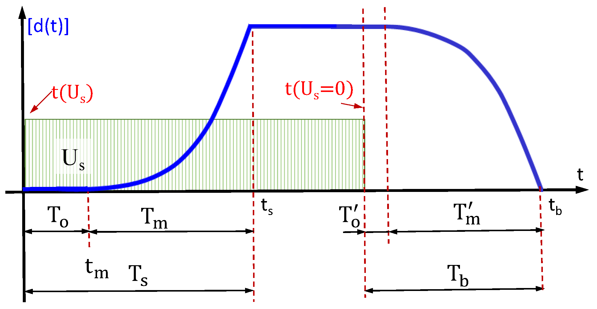
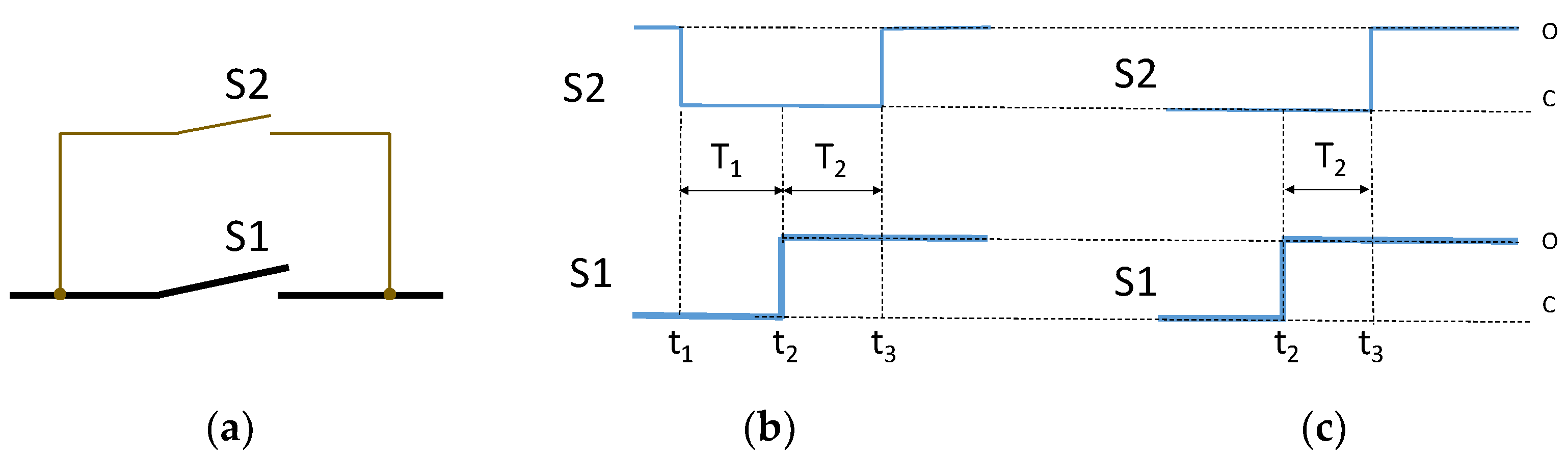
- At the continuous operation stage, arcing contacts remain opened so the load current flows through the main S1 current path (Figure 1b). Immediately before the commencement of the switching-off stage, arcing contacts S2 are closed at the t1 moment. During the few milliseconds of T1 time, both contacts are closed. With regard to the arcing contacts, due to the significantly lower resistance of the main current path, the load current invariably flows through the main contacts. At the next stage, at the t2 moment, the main contacts are opened. For the T2 time duration, the current flows through the arcing contacts. At t3, the arcing contacts are opened and the arc is quenched in the vacuum or noble gas environment.
- In the second mode of operation (Figure 1c), for the duration of continuous operation, both contacts are closed; however, the main current flows through the main current path due to the lower resistance of the main contacts. At t2, the main contacts are opened. Similarly to the first operation mode, during the T2 time duration, the current flows through the arcing contacts. At t3, the arc quenching process initiation occurs at the VI contacts.
3. Experimental Verification
3.1. Objects under Research
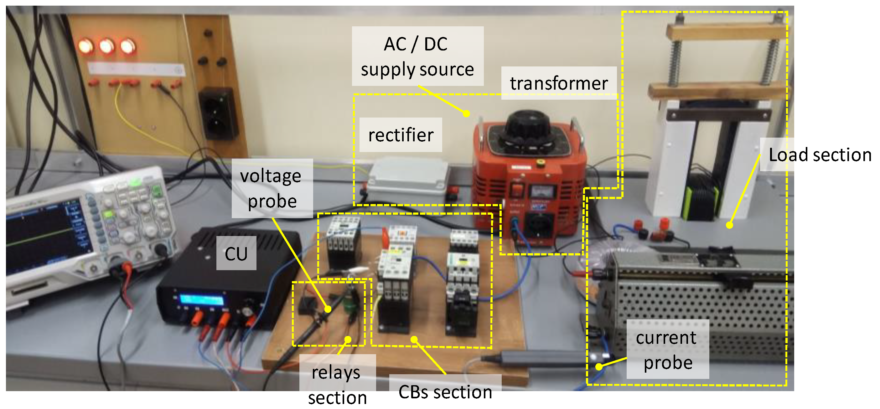
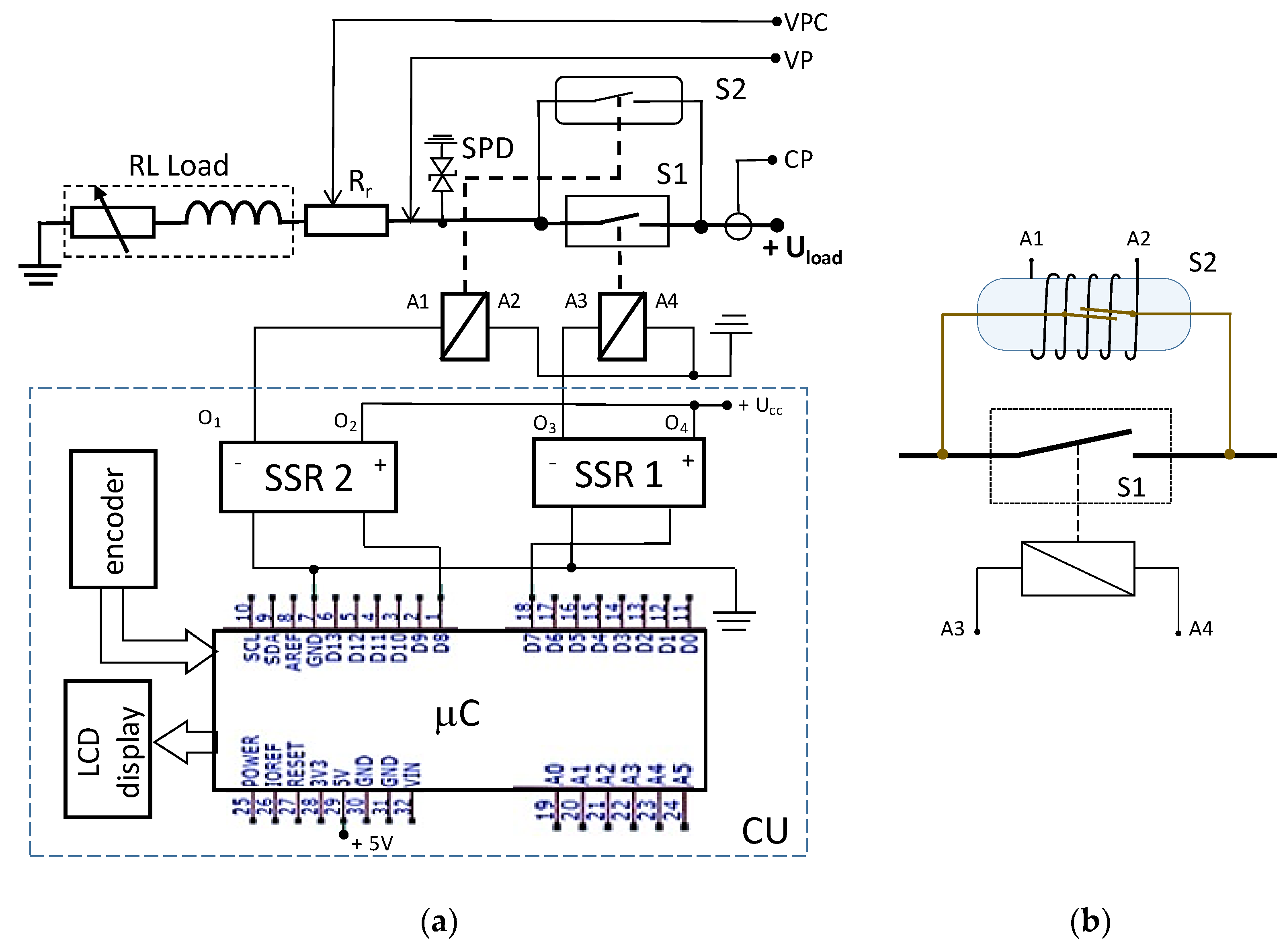
3.2. Control Unit and Test Stand Description
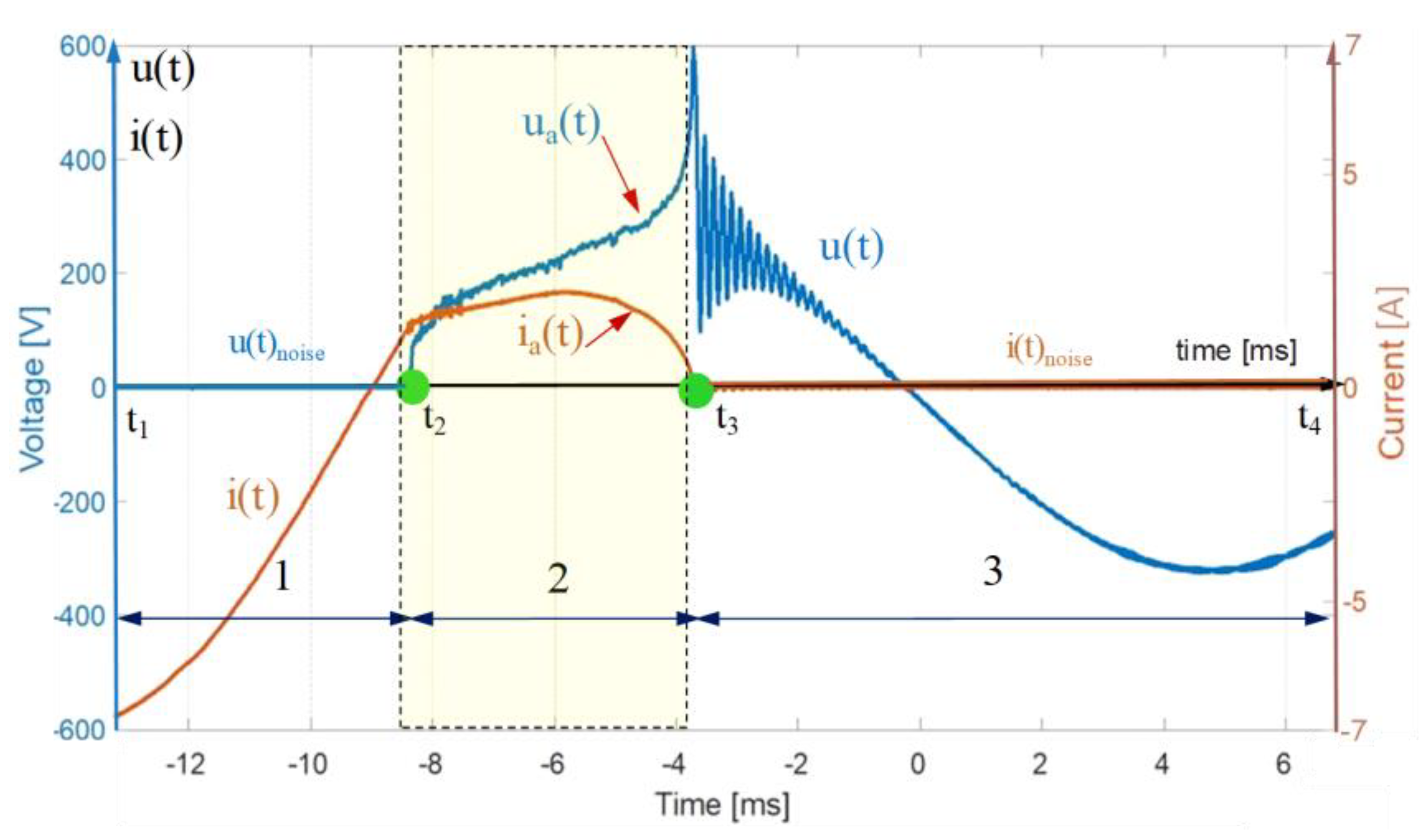
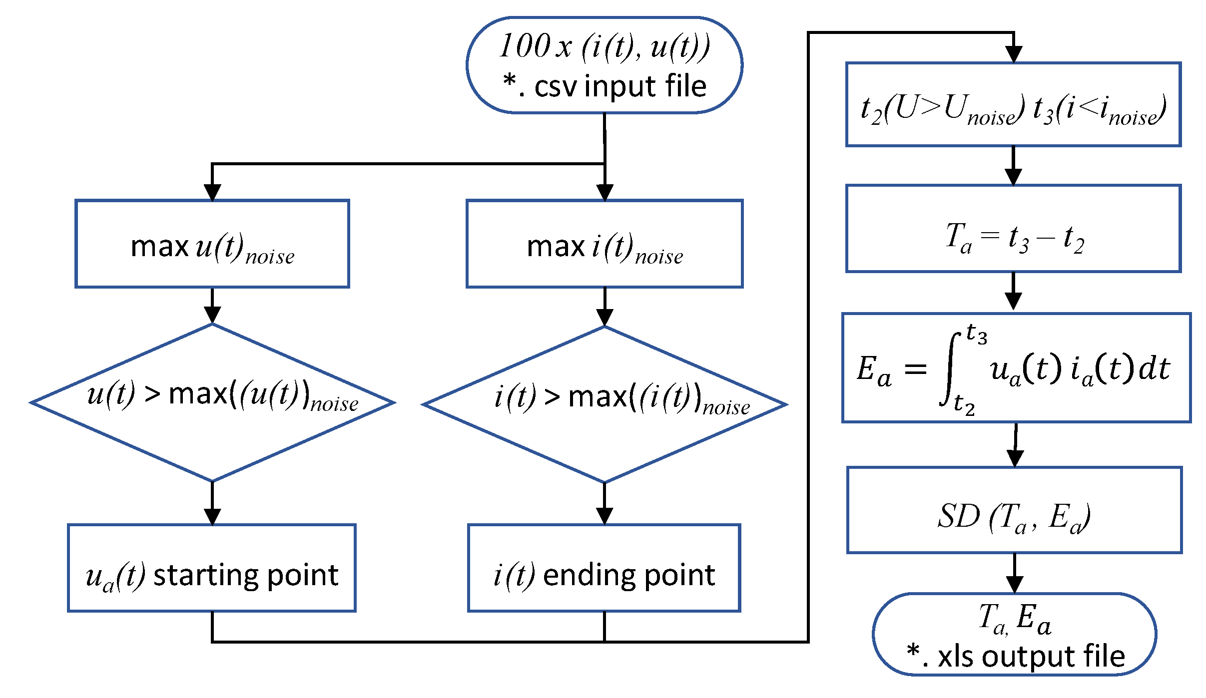
3.3. Measurement Procedure and Data Post-Processing
- Tests on the air-insulated electromagnetic contactors used as a single current interrupter for the inductively loaded circuit;
- Tests on air-insulated EMCs coupled with a vacuum reed relay switches acting as arcing contacts.
- For each contactor operating as a single air-insulated current interrupter;
- For each “contactor –relay” configuration.
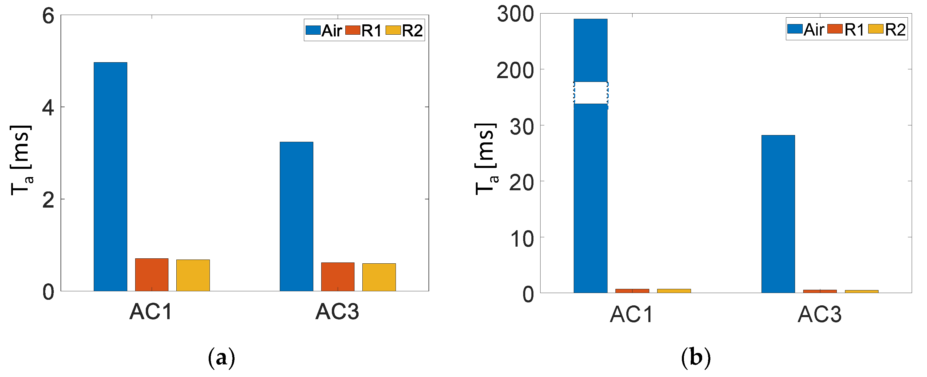
- Arcing time (Ta);
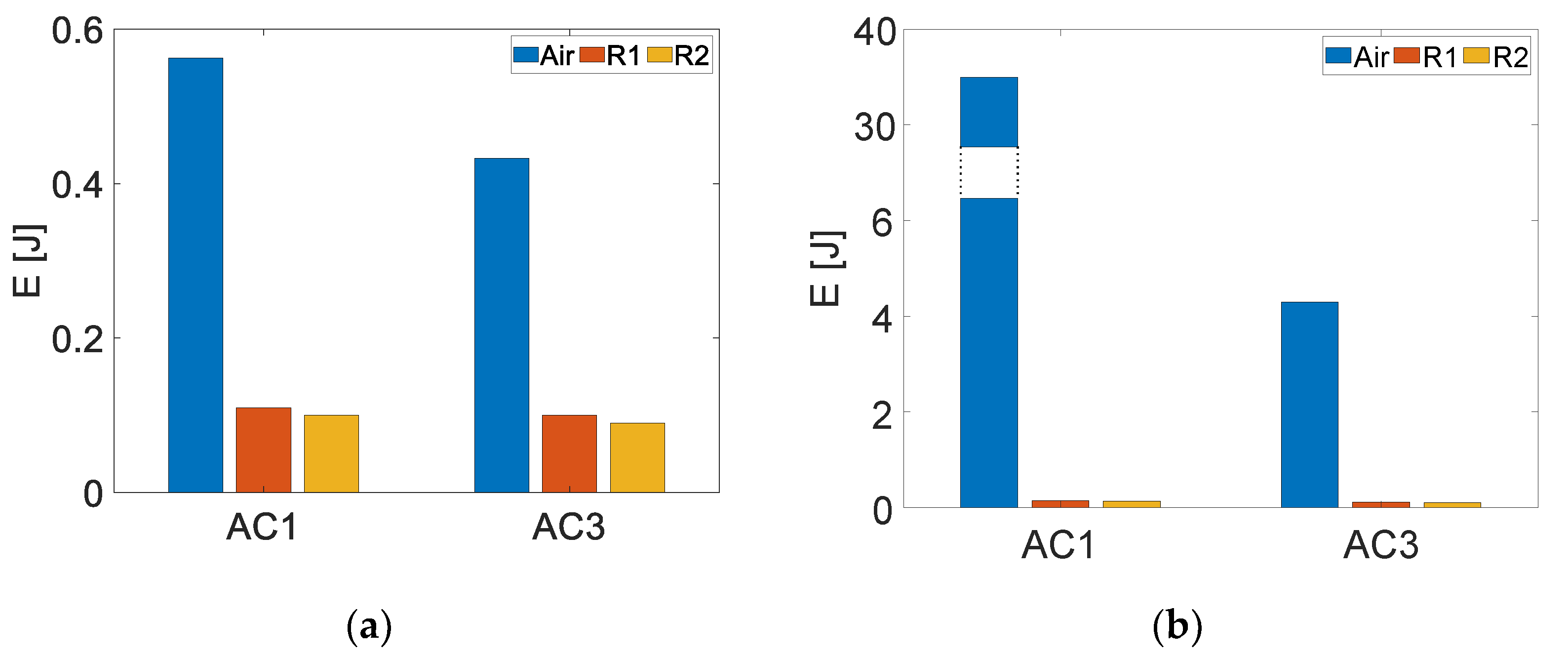
- Arc energy (Ea);
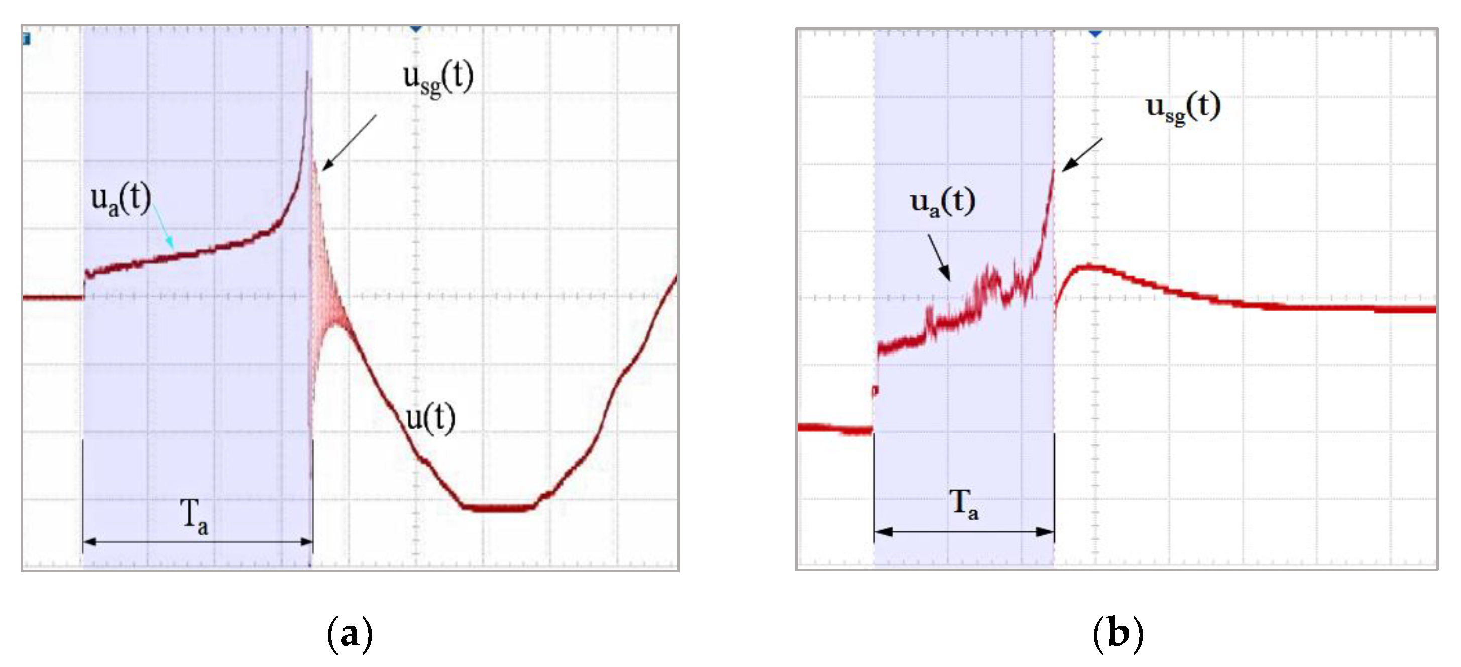
- Level of voltage surges occurring during current breaking (Usg) (if these occurred).
3.4. Measurements Results
4. Summary
Author Contributions
Funding
Institutional Review Board Statement
Informed Consent Statement
Data Availability Statement
Conflicts of Interest
References
- Wu, Z.; Wu, G.; Chen, C.; Fang, Y.; Pan, L.; Huang, H. A novel breaking strategy for electrical endurance extension of electromagnetic alternating current contactors. IEEE Trans. Compon. Packag. Manuf. Technol. 2016, 6, 749–756. [Google Scholar] [CrossRef]
- Valentine, R.D. A Perspective of Low-Voltage Circuit Breaker Interrupting Rating. IEEE Trans. Ind. Appl. 2000, 36, 916–919. [Google Scholar] [CrossRef]
- Derevyankin, P.G.; Frolov, V.Y.; Kriskovets, D.S.; Yushin, B.A. Analysis of the Electrophysical and Thermophysical Properties of Copper-Graphite Material for Arcing Contacts of a High-Current Low-Voltage Circuit Breaker. In Proceedings of the 2021 IEEE Conference of Russian Young Researchers in Electrical and Electronic Engineering (ElConRus), St. Peterburg, Moscow, Russia, 26–29 January 2021. [Google Scholar]
- Mützel, T.; Niederreuther, R. Development of Contact Material Solutions for Low-Voltage Circuit Breaker Applications. In Proceedings of the 2011 IEEE 57th Holm Conference on Electrical Contacts (Holm 2011), Minneapolis, MN, USA, 11–14 September 2011. [Google Scholar]
- Honmat, H.; Kimura, S.; Shoji, K.; Wakatsuki, N. Arc discharge and surge suppression during a breaking operation of a magnetic relay. In Proceedings of the 53rd IEEE HOLM Conference on Electrical Contacts, Pittsburgh, PA, USA, 16–19 September 2007; pp. 280–283. [Google Scholar]
- Cai, Z.; Gong, H.; Ma, S. Analysis and improve of electromagnet mechanism for integrated control and protective switching devices. In Proceedings of the 2008 International Conference on Electrical Machines and Systems (ICEMS), Wuhan, China, 17–20 October 2008; pp. 4277–4280. [Google Scholar]
- Fazel, M.; Gholam-Abbas, N.; Saif, M. A New Topology of a Fast Proactive Hybrid DC Circuit Breaker for MT-HVDC Grids. Sustainability 2019, 11, 4493. [Google Scholar]
- Niehoff, R. Circuit Breaker with Hybrid Switch. U.S. Patent US9947496B2, 17 April 2018. [Google Scholar]
- Xu, C.; Damle, T.; Graber, L. A Survey on Mechanical Switches for Hybrid Circuit Breakers. In Proceedings of the 2019 IEEE Power & Energy Society General Meeting, Atlanta, GA, USA, 4–8 August 2019. [Google Scholar]
- Swingler, J.; McBride, J.W. Micro-Arcing and Arc Erosion Minimization Using a DC Hybrid Switching Device. IEEE Trans. Compon. Packag. Technol. 2008, 31, 425–430. [Google Scholar] [CrossRef] [Green Version]
- Thakur, R.; Ravi, B.L. Design and Development of Microcontroller based Controlled Switching Device for Transformer. In Proceedings of the International Conference on Innovative Mechanisms for Industry Applications (ICIMIA 2017), Bengaluru, India, 21–23 February 2017; pp. 349–353. [Google Scholar]
- Jehle, A.; Biela, J. Optimization of Hybrid Current-Injection Circuit Breakers including Mechanical Switch Limitations. In Proceedings of the 21st European Conference on Power Electronics and Applications, Genova, Italy, 2–6 September 2019; pp. 1–11. [Google Scholar]
- Wakatsuki, N.; Yonezawa, Y. Relay Contacts of Multi-Electrodes with Timely Controlled Operation for Arc Discharge Suppression. In Proceedings of the 50th IEEE Holm Conference on Electrical Contacts, Seattle, WA, USA, 23 September 2004; pp. 474–479. [Google Scholar]
- Chen, L.; Chen, Z. Intelligent AC Contactor with Contacts for Switching Reactive Compensation Device. In Proceedings of the APAP 2011: International Conference on Advanced Power System Automation and Protection, Beijing, China, 16–20 October 2011; pp. 781–784. [Google Scholar]
- Collombet, M.; Lacroix, B. LV circuit-breakers confronted with harmonic, transient and cyclic currents. Cahier Tech. Merlin Gerin 2011, 182, 12. [Google Scholar]
- Hillary-Tin, A.; Abu-Siada, M.S. Impact of Harmonics on the Performance of Over-Current Relays. In Proceedings of the APAP 2011: International Conference on Advanced Power System Automation and Protection, Beijing, China, 16–20 October 2011. [Google Scholar]
- Kamtip, S.; Bhumkittipich, K. Comparison between Mechanical Circuit Breaker and Solid State Circuit Breaker under Abnormal Conditions for Low Voltage Systems. In Proceedings of the 18th International Conference on Electrical Machines and Systems (ICEMS), Pattaya, Thailand, 25–28 October 2015; pp. 1091–1096. [Google Scholar]
- Liu, Y.; Cheng, D.; Ji, L.; Geng, Y. Dynamic Characteristic and Contact Bounce Analysis for an AC Contactor with PWM Controlled Coil. In Proceedings of the 53rd IEEE Holm Conference on Electrical Contacts, Pittsburgh, PA, USA, 16–19 September 2007; pp. 289–293. [Google Scholar]
- Zong, M.; Qi, L.; Wang, X.; Zhang, Y.; Wang, S. A Review of Intelligent Contactor Design and Its Control Technology. Int. J. Control. Autom. 2016, 9, 389–402. [Google Scholar] [CrossRef]
- Xu, Z.; Zhang, P. Intelligent Control Technology of AC Contactor. 2005 IEEE/PES Transmission & Distribution Conference & Exposition: Asia and Pacific, Dalian, China, 18 August 2005; pp. 1–6. [Google Scholar]
- Avila, L.I.M.; Castatnñón, L.E.G.; Ortiz, E.R.C. An Intelligent Control Approach for Designing a Low Voltage DC Breaker. In Proceedings of the 2012 VI Andean Region International Conference, Cuenca, Ecuador, 7–9 November 2012; pp. 163–166. [Google Scholar]
- Lacroix, M.; Gutierrez, A. Controlled Switching and Circuit Breaker Monitoring. In Proceedings of the IEEE 37th Central America and Panama Convention (CONCAPAN XXXVII), Managua, Nicaragua, 15–17 November 2017; pp. 1–5. [Google Scholar]
- Song, M.-G.; Kim, S.-M.; Li, K.-B. Synchronized Switching Technique for Elimination of Unexpected Output Pulses in Hybrid Active NPC inverter. In Proceedings of the 2019 IEEE 4th International Future Energy Electronics Conference (IFEEC), Singapore, 25–28 November 2019. [Google Scholar]
- JCGM 200:2012. International Vocabulary of Metrology—Basic and General Concepts and Associated Terms (VIPM), 3rd ed.; Joint Committee for Guides in Metrology: Sèvres, France, 2012. [Google Scholar]
- Bauchire, J.M.; Hong, D.; Rabat, H.; Riquel, G. Radiation of transient high-current arcs: Energy measurements in the optical range. J. Phys. Conf. Ser. 2012, 406. [Google Scholar] [CrossRef]
- Xu, X.; Li, Y.; Tan, X. Research of Monitoring Switching-generated Arcing Current during Opening and Closing Process using Rogowski Coil. In Proceedings of the 2008 International Conference on Condition Monitoring and Diagnosis, Beijing, China, 21–24 April 2008. [Google Scholar]
- Sekulic, W.R.; McNutt, P. Evaluating the Incident Energy of Arcs in Photovoltaic DC Systems: Comparison Between Calculated and Experimental Data. IEEE Trans. Ind. Appl. 2020, 56, 3224–3230. [Google Scholar] [CrossRef]
- Porte, M.; Razafiarivelo, J.; Carvou, E.; Ben Jemaa, N. Contact heating by long arcing during connector disconnection. In Proceedings of the 51st IEEE Holm Conference on Electrical Contacts, Chicago, IL, USA, 26–28 September 2005; pp. 360–365. [Google Scholar]
- Donen, T.; Takai, Y.; Ochi, S. Effect of Arcing Time with Capacitive Making Current on Contact Welding in Vacuum. In Proceedings of the 2018 28th International Symposium on Discharges and Electrical Insulation in Vacuum (ISDEIV), Greifswald, Germany, 23–28 September 2018; pp. 197–200. [Google Scholar]
- Murakami, M.; Ryonai, H.; Kubono, T.; Sekikawa, J. Properties of Short Arc Phenomena on AgCu Electrical Contact Pairs for Automotive Electronics Devices. In Proceedings of the 53rd IEEE Holm Conference on Electrical Contacts, Pittsburgh, PA, USA, 16–19 September 2007; pp. 145–150. [Google Scholar]
- Swingler, J. Performance and arcing characteristics of Ag/Ni contact materials under DC resistive load conditions. IET Sci. Meas. Technol. 2011, 5, 37–45. [Google Scholar] [CrossRef]
- Borkowski, P.; Walczuk, E. Computerized measurement stands for testing static and dynamic electrical contact welding. Measurement 2011, 44, 1618–1627. [Google Scholar] [CrossRef]
- Smugala, D.; Bonk, M. Study of Arc Parameters of AC Relays Operating under Distorted Supply Voltage Conditions. Energies 2020, 13, 4785. [Google Scholar] [CrossRef]
- Cho, D.-J.; Kang, J.S.; Kim, B.-J.; Jin, Y.H. An analysis of electromagnetic characteristics and mechanical load characteristics of actuator for 4 pole MC. In Proceedings of the 3rd International Conference on Electric Power Equipment—Switching Technology (ICEPE-ST), Busan, Korea, 25–27 October 2015; pp. 354–356. [Google Scholar]
- IEEE Std 1459-2010. IEEE Standard Definitions for the Measurement of Electric Power Quantities under Sinusoidal, Nonsinusoidal, Balanced or Unbalanced Conditions; IEEE: Piscataway, NJ, USA, 2010. [Google Scholar]


| Sample | Un [V] | In [A] (AC-3) | Us [V] | Ts [ms] | Tb [ms] | Tcb [ms] |
|---|---|---|---|---|---|---|
| CB1 | 400 | 16 | 24 | 30.53 * | 31.00 * | 0.69 * |
| CB2 | 400 | 17 | 24 | 44.52 * | 28.55 * | 0.72 * |
| Sample | Umax [kV] | In [A] | Us [V] | Rc [mΩ] | Ri [GΩ} | Ts [ms] | Tb [ms] | Tcb [ms] |
|---|---|---|---|---|---|---|---|---|
| R1 | 7 | 2 | 24 | 250 | 1000 | 2 | 3 | 0.82 * |
| R2 | 7.5 | 5 | 24 | 150 | 1000 | 3.2 | 1.5 | 0.68 * |
Publisher’s Note: MDPI stays neutral with regard to jurisdictional claims in published maps and institutional affiliations. |
© 2021 by the authors. Licensee MDPI, Basel, Switzerland. This article is an open access article distributed under the terms and conditions of the Creative Commons Attribution (CC BY) license (https://creativecommons.org/licenses/by/4.0/).
Share and Cite
Smugala, D.; Bonk, M. Switching Arc Energy Limitation Approach for LV Circuit Breakers. Energies 2021, 14, 6774. https://doi.org/10.3390/en14206774
Smugala D, Bonk M. Switching Arc Energy Limitation Approach for LV Circuit Breakers. Energies. 2021; 14(20):6774. https://doi.org/10.3390/en14206774
Chicago/Turabian StyleSmugala, Dariusz, and Michal Bonk. 2021. "Switching Arc Energy Limitation Approach for LV Circuit Breakers" Energies 14, no. 20: 6774. https://doi.org/10.3390/en14206774
APA StyleSmugala, D., & Bonk, M. (2021). Switching Arc Energy Limitation Approach for LV Circuit Breakers. Energies, 14(20), 6774. https://doi.org/10.3390/en14206774