
Grasped Object Weight Compensation in Reference to Impedance Controlled Robots


Abstract

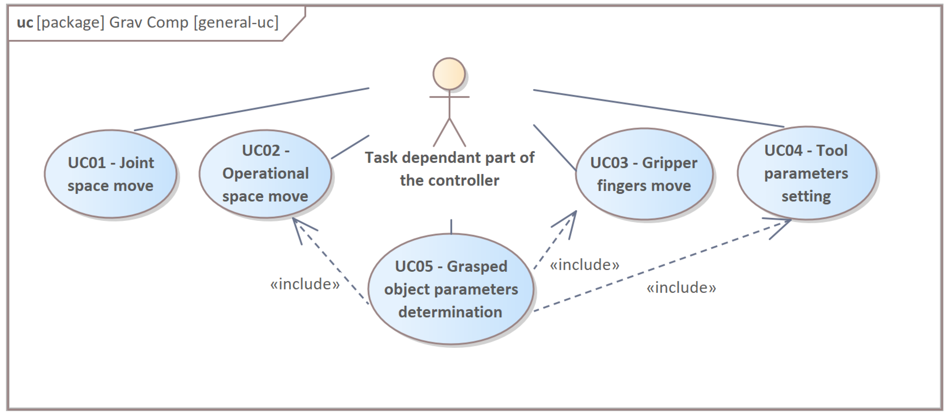
1. Introduction
2. Control System
- task/ga: Group of Agents with the specific task implemented.
- core/a: Agent that realizes the core behaviours that are demanded from the point of view of the wide range of applications formulated in task/ga.
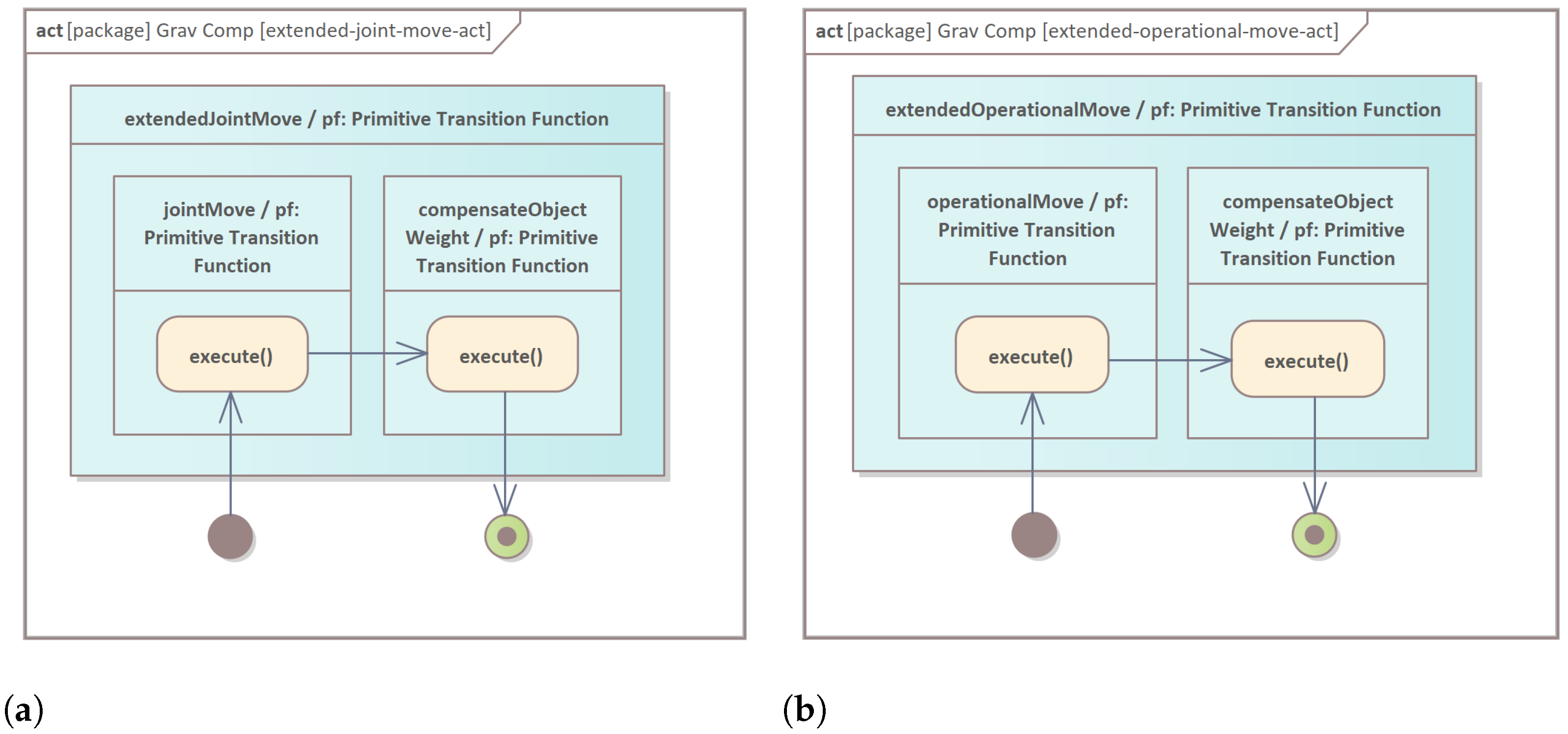
2.1. Primitive Transition Function core/a.cs.jointMove/pf
2.2. Primitive Transition Function core/a.cs.operationalMove/pf
2.3. Primitive Transition Function core/a.cs.compensateObjectWeight/pf
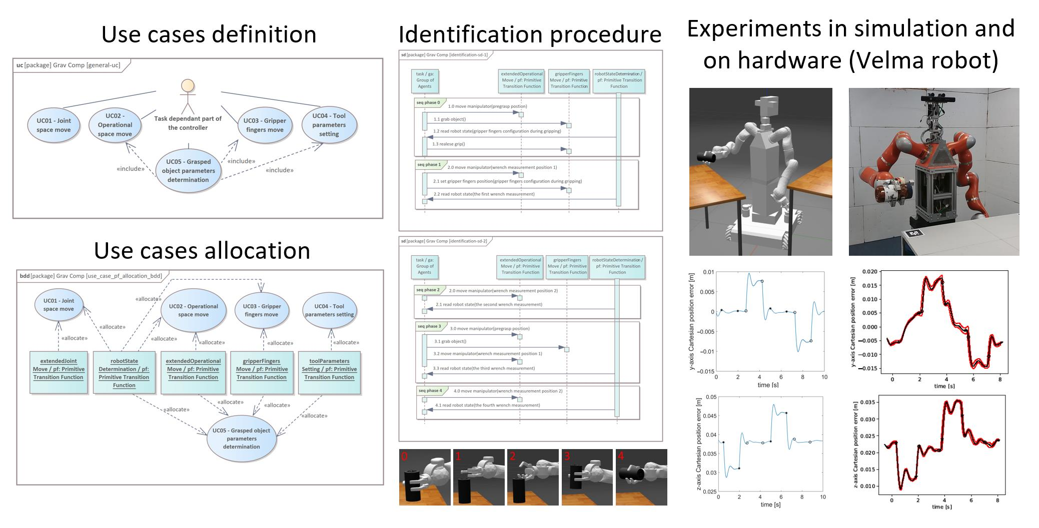
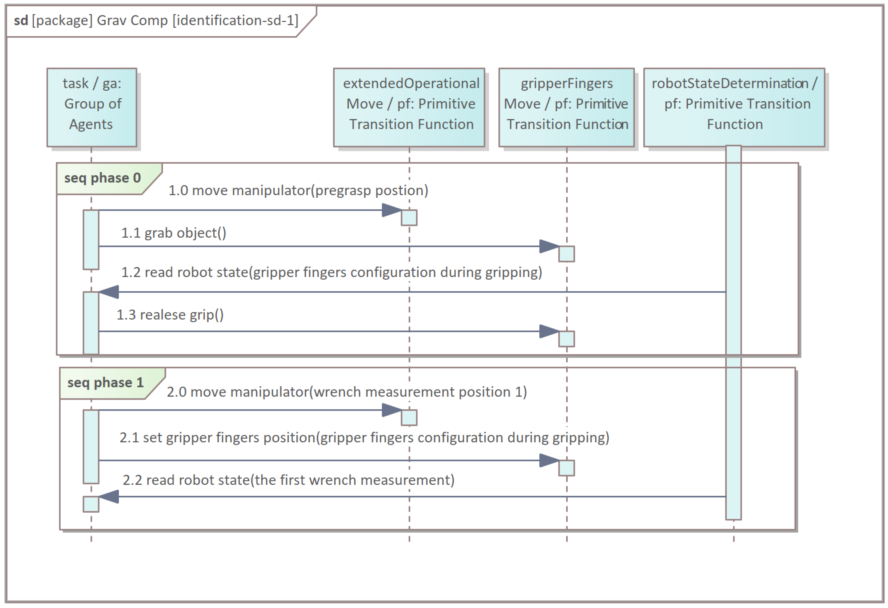
3. The Identification Procedure of the Object’s Parameters
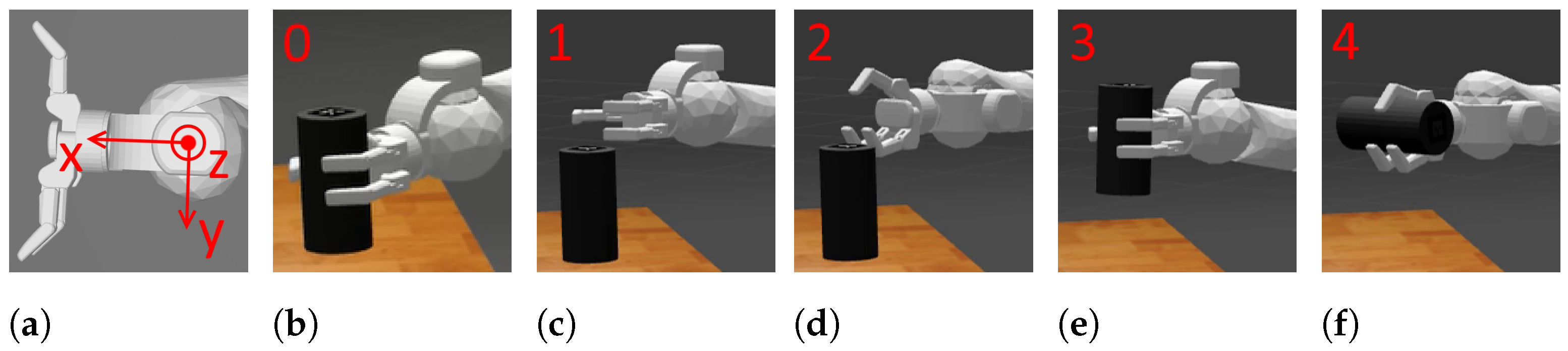
- 0.
- The selected manipulator changes the position of its gripper in order to check the grasp configuration of the gripper’s fingers (Figure 9b). When the gripper tightens on the object, the measurement of the gripper’s joint positions is taken. The grip is released.
- 1.
- The manipulator reaches the reference position for the first wrench measurement (Figure 9c). The gripper’s joint positions are set according to phase 0. The measurement is taken.
- 2.
- The gripper rotates around the axis x of the frame by , and the second reference measurement is taken (Figure 9d).
- 3.
- The manipulator grasps the object with its gripper and reaches the same position as in phase 1. The third measurement is taken (Figure 9e).
- 4.
- The arm reaches the same position as in phase 2, and the fourth measurement is taken (Figure 9f). Identification parameters can be computed and transmitted into agent core/a.
4. The Verification of the Grasped Object Weight Compensation Algorithm
4.1. The Specific Realisation of Impedance Control Law for the Velma Service Robot
4.2. Exemplary Results of Experiments
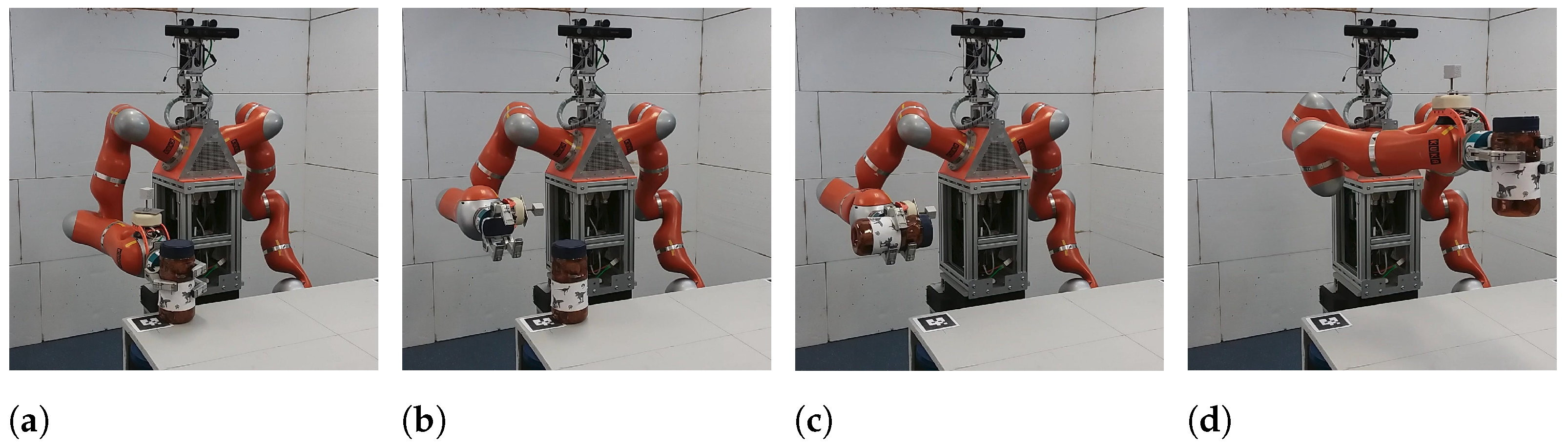
- The robot performed the identification procedure (Section 3, Figure 10a–e, starting from the convenient configuration (Figure 10a). According to phase 0 of the procedure, the robot checked the grasp configuration of the fingers of its right gripper (Figure 10b). Then, the robot took two reference wrench measurements (Figure 10c), and after that, it grasped the object (Figure 10d). Ultimately, the robot took two last wrench measurements (Figure 10e), and thanks to this, the desired parameters could be computed.
- The robot executed a sequence of the movements in Cartesian impedance control mode with linear interpolation (analogous to that described in [23]) between points (vertices) of a square (Figure 10f,g and Figure 11) lying in the plane perpendicular to the x-axis of the global coordinate system (Figure 10a).
- The robot put away the object on the other table (Figure 10h).
5. Conclusions
Author Contributions
Funding
Conflicts of Interest
References
- Khatib, O. Object Manipulation in a Multi-Effector Robot System. In Proceedings of the 4th International Symposium on Robotics, Santa Clara, CA, USA, 3–7 May 1998; MIT Press: Cambridge, MA, USA; pp. 137–144. [Google Scholar]
- Seredyński, D.; Winiarski, T.; Banachowicz, K.; Zieliński, C. Grasp planning taking into account the external wrenches acting on the grasped object. In Proceedings of the 10th International Workshop on Robot Motion and Control (RoMoCo), Poznań, Poland, 8–9 July 2015; pp. 40–45. [Google Scholar]
- Seredyński, D.; Szynkiewicz, W. Fast Grasp Learning for Novel Objects. Recent Advances in Automation, Robotics and Measuring Techniques. In Advances in Intelligent Systems and Computing (AISC); Springer: Berlin, Germany, 2016; Volume 440, pp. 681–692. [Google Scholar]
- Mazur, A.; Frontkiewicz, M.; Domski, W. Position-force control of nonholonomic mobile manipulator with simple holonomic constraint. In Proceedings of the 10th International Workshop on Robot Motion and Control (RoMoCo), Poznań, Poland, 6–8 July 2015; pp. 257–262. [Google Scholar]
- Winiarski, T.; Banachowicz, K.; Walęcki, M.; Bohren, J. Multibehavioral position–force manipulator controller. In Proceedings of the 21th IEEE International Conference on Methods and Models in Automation and Robotics, MMAR, Międzyzdroje, Poland, 29 August–1 September 2016; pp. 651–656. [Google Scholar]
- Kozakiewicz, B.; Winiarski, T. Spring based on flat permanent magnets: Design, analysis and use in variable stiffness actuator. Facta Univ. Ser. Mech. Eng. 2021. [Google Scholar] [CrossRef]
- Jezierski, E. Low cost impedance controller for robotic gripper drive with DC motor. In Proceedings of the 20th International Conference on Methods and Models in Automation and Robotics (MMAR), Międzyzdroje, Poland, 24–27 August 2015; pp. 806–811. [Google Scholar]
- Winiarski, T.; Banachowicz, K.; Seredyński, D. Multi-Sensory Feedback Control in Door Approaching and Opening; Intelligent Systems’2014; Springer International Publishing: New York, NY, USA, 2015; Volume 323, pp. 57–70. [Google Scholar]
- Pratt, G.A. Low Impedance Walking Robots. Integr. Comp. Biol. 2002, 42, 174–181. [Google Scholar] [CrossRef]
- Ghorbanpour, A.; Richter, H. An Overview of Energy-Optimal Impedance Control of Cooperative Robot Manipulators. arXiv 2021, arXiv:2106.07491. [Google Scholar]
- Ott, C.; Albu-Schäffer, A.; Kugi, A.; Hirzinger, G. On the Passivity-Based Impedance Control of Flexible Joint Robots. IEEE Trans. Robot. 2008, 24, 416–429. [Google Scholar] [CrossRef]
- Friedenthal, S.; Moore, A.; Steiner, R. A Practical Guide to SysML: The Systems Modeling Language, 3rd ed.; Morgan Kaufmann; Elsevier: Burlington, MA, USA, 2015. [Google Scholar]
- Open Management Group Systems Modeling Language-Version 1.6. 2019. Available online: https://www.omg.org/spec/SysML/1.6/PDF (accessed on 10 October 2021).
- Winiarski, T.; Węgierek, M.; Seredyński, D.; Dudek, W.; Banachowicz, K.; Zieliński, C. EARL–Embodied Agent-Based Robot Control Systems Modelling Language. Electronics 2020, 9, 379. [Google Scholar] [CrossRef]
- EARL—Embodied Agent-Based cybeR-Physical Control Systems Modelling Language-Version 1.2-Reference Manual. 2021. Available online: https://www.robotyka.ia.pw.edu.pl/papers/earl-1_2.pdf (accessed on 10 October 2021).
- Karwowski, J.; Dudek, W.; Węgierek, M.; Winiarski, T. HuBeRo-a Framework to Simulate Human Behaviour in Robot Research. J. Autom. Mob. Robot. Intell. Syst. 2021, 15, 31–38. [Google Scholar] [CrossRef]
- Winiarski, T.; Dudek, W.; Stefańczyk, M.; Łukasz, Z.; Giełdowski, D.; Seredyński, D. An intent-based approach for creating assistive robots’ control systems. arXiv 2020, arXiv:2005.12106. [Google Scholar]
- Kornuta, T.; Zieliński, C.; Winiarski, T. A universal architectural pattern and specification method for robot control system design. Bull. Pol. Acad. Sci. Tech. Sci. 2020, 68, 3–29. [Google Scholar] [CrossRef]
- Zieliński, C.; Stefańczyk, M.; Kornuta, T.; Figat, M.; Dudek, W.; Szynkiewicz, W.; Kasprzak, W.; Figat, J.; Szlenk, M.; Winiarski, T.; et al. Variable structure robot control systems: The RAPP approach. Robot. Auton. Syst. 2017, 94, 226–244. [Google Scholar] [CrossRef]
- Dudek, W.; Winiarski, T. Scheduling of a Robot’s Tasks With the TaskER Framework. IEEE Access 2020, 8, 161449–161471. [Google Scholar] [CrossRef]
- Kasprzak, W.; Szynkiewicz, W.; Stefańczyk, M.; Dudek, W.; Węgierek, M.; Seredyński, D.; Figat, M.; Zieliński, C. Agent-based approach to the design of a multimodal interface for cyber-security event visualisation control. Bull. Pol. Acad. Sci. Tech. Sci. 2020, 68, 1187–1205. [Google Scholar] [CrossRef]
- Dao, P.B. Learning Feedforward Control Using Multiagent Control Approach for Motion Control Systems. Energies 2021, 14, 420. [Google Scholar] [CrossRef]
- Winiarski, T.; Banachowicz, K.; Seredyński, D. Two mode impedance control of Velma service robot redundant arm. Progress in Automation, Robotics and Measuring Techniques. Vol. 2 Robotics. In Advances in Intelligent Systems and Computing (AISC); Springer: Berlin, Germany, 2015; Volume 351, pp. 319–328. [Google Scholar]
- Sentis, L.; Khatib, O. Synthesis of whole-body behaviors through hierarchical control of behavioral primitives. Int. J. Humanoid Robot. 2005, 2, 505–518. [Google Scholar] [CrossRef]
- Dietrich, A.; Albu-Schäffer, A.; Hirzinger, G. On continuous null space projections for torque-based, hierarchical, multi-objective manipulation. In Proceedings of the IEEE International Conference on Robotics and Automation (ICRA), St. Paul, MN, USA, 14–19 May 2016; pp. 2978–2985. [Google Scholar]
- Seredyński, D.; Banachowicz, K.; Winiarski, T. Graph–based potential field for the end–effector control within the torque–based task hierarchy. In Proceedings of the 21th IEEE International Conference on Methods and Models in Automation and Robotics, MMAR, Międzyzdroje, Poland, 29 August–1 September 2016; pp. 645–650. [Google Scholar]
- Ratajczak, J.; Tchoń, K. On dynamically consistent Jacobian inverse for non-holonomic robotic systems. Arch. Control. Sci. 2017, 4, 555–573. [Google Scholar] [CrossRef][Green Version]
- Dietrich, A.; Wimböck, T.; Täubig, H.; Albu-Schäffer, A.; Hirzinger, G. Extensions to reactive self-collision avoidance for torque and position controlled humanoids. In Proceedings of the IEEE International Conference on Robotics and Automation, Shanghai, China, 9–13 May 2011; pp. 3455–3462. [Google Scholar]
- Dietrich, A.; Wimböck, T.; Albu-Schäffer, A.; Hirzinger, G. Reactive Whole-Body Control: Dynamic Mobile Manipulation Using a Large Number of Actuated Degrees of Freedom. IEEE Robot. Autom. Mag. 2012, 19, 20–33. [Google Scholar] [CrossRef]
- Albu-Schäffer, A.; Ott, C.; Frese, U.; Hirzinger, G. Cartesian impedance control of redundant robots: Recent results with the DLR-light-weight-arms. In Proceedings of the IEEE International Conference on Robotics and Automation, Taipei, Taiwan, 14–19 September 2003; Volume 3, pp. 3704–3709. [Google Scholar]
- Winiarski, T.; Banachowicz, K. Opening a door with a redundant impedance controlled robot. In Proceedings of the 9th Workshop on Robot Motion & Control (RoMoCo), Kuślin, Poland, 3–5 July 2013; pp. 221–226. [Google Scholar]
- Mavrakis, N.; Ghalamzan, A.; Stolkin, R.; Baronti, L.; Kopicki, M.; Castellani, M. Analysis of the inertia and dynamics of grasped objects, for choosing optimal grasps to enable torque-efficient post-grasp manipulations. In Proceedings of the IEEE-RAS 16th International Conference on Humanoid Robots (Humanoids), Cancun, Mexico, 15–17 November 2016; pp. 171–178. [Google Scholar]
- Winiarski, T.; Sikora, J.; Seredyński, D.; Dudek, W. DAIMM Simulation Platform for Dual-Arm Impedance Controlled Mobile Manipulation. In Proceedings of the 7th International Conference on Automation, Robotics and Applications (ICARA), Prague, Czech Republic, 4–6 February 2021; pp. 180–184. [Google Scholar] [CrossRef]
- Seredyński, D.; Winiarski, T.; Zieliński, C. FABRIC: Framework for Agent-Based Robot Control Systems. In Proceedings of the 12th International Workshop on Robot Motion and Control (RoMoCo), Poznań, Poland, 8–10 July 2019; pp. 215–222. [Google Scholar]
- Piperidis, S.; Chrysomallis, I.; Georgakopoulos, S.; Ghionis, N.; Doitsidis, L.; Tsourveloudis, N. A ROS-Based Energy Management System for a Prototype Fuel Cell Hybrid Vehicle. Energies 2021, 14, 1964. [Google Scholar] [CrossRef]
- Quigley, M.; Conley, K.; Gerkey, B.; Faust, J.; Foote, T.; Leibs, J.; Wheeler, R.; Ng, A.Y. ROS: An Open-Source Robot Operating System. In Proceedings of the ICRA Workshop on Open Source Software, Kobe, Japan, 12–17 May 2009; Volume 3.2. [Google Scholar]
- Bruyninckx, H. OROCOS: Design and implementation of a robot control software framework. In Proceedings of the IEEE International Conference on Robotics and Automation, Washington, DC, USA, 11–15 May 2002. [Google Scholar]
- Walęcki, M.; Banachowicz, K.; Winiarski, T. Research oriented motor controllers for robotic applications. In Robot Motion and Control 2011 (LNCiS) Lecture Notes in Control & Information Sciences; Springer Limited: London, UK, 2012; Volume 422, pp. 193–203. [Google Scholar]
- Woliński, Ł.; Wojtyra, M. Comparison of Dynamic Properties of Two KUKA Lightweight Robots. In ROMANSY 21-Robot Design, Dynamics and Control; Springer International Publishing: New York, NY, USA, 2016; pp. 413–420. [Google Scholar]
- Schreiber, G.; Stemmer, A.; Bischoff, R. The fast research interface for the kuka lightweight robot. In Proceedings of the IEEE Workshop on Innovative Robot Control Architectures for Demanding (Research) Applications How to Modify and Enhance Commercial Controllers (ICRA), Anchorage, AK, USA, 3–7 May 2010; pp. 15–21. [Google Scholar]
- Mavrakis, N.; Stolkin, R. Estimation and exploitation of objects’ inertial parameters in robotic grasping and manipulation: A survey. Robot. Auton. Syst. 2020, 124, 103374. [Google Scholar] [CrossRef]
- Shahid, A.A.; Roveda, L.; Piga, D.; Braghin, F. Learning continuous control actions for robotic grasping with reinforcement learning. In Proceedings of the 2020 IEEE International Conference on Systems, Man, and Cybernetics (SMC), Toronto, ON, Canada, 11–14 October 2020; pp. 4066–4072. [Google Scholar]
- Roveda, L.; Haghshenas, S.; Caimmi, M.; Pedrocchi, N.; Molinari Tosatti, L. Assisting operators in heavy industrial tasks: On the design of an optimized cooperative impedance fuzzy-controller with embedded safety rules. Front. Robot. AI 2019, 6, 75. [Google Scholar] [CrossRef]
- Roveda, L.; Haghshenas, S.; Prini, A.; Dinon, T.; Pedrocchi, N.; Braghin, F.; Tosatti, L.M. Fuzzy impedance control for enhancing capabilities of humans in onerous tasks execution. In Proceedings of the 2018 15th International Conference on Ubiquitous Robots (UR), Honolulu, HI, USA, 26–30 June 2018; pp. 406–411. [Google Scholar]
- Roveda, L.; Maskani, J.; Franceschi, P.; Abdi, A.; Braghin, F.; Tosatti, L.M.; Pedrocchi, N. Model-based reinforcement learning variable impedance control for human-robot collaboration. J. Intell. Robot. Syst. 2020, 100, 417–433. [Google Scholar] [CrossRef]
- Swevers, J.; Verdonck, W.; Naumer, B.; Pieters, S.; Biber, E. An experimental robot load identification method for industrial application. Int. J. Robot. Res. 2002, 21, 701–712. [Google Scholar] [CrossRef]
- Kubus, D.; Kroger, T.; Wahl, F.M. On-line estimation of inertial parameters using a recursive total least-squares approach. In Proceedings of the 2008 IEEE/RSJ International Conference on Intelligent Robots and Systems (IROS), Nice, France, 22–26 September 2008; pp. 3845–3852. [Google Scholar]
- Zieliński, C.; Winiarski, T. Motion Generation in the MRROC++ Robot Programming Framework. Int. J. Robot. Res. 2010, 29, 386–413. [Google Scholar] [CrossRef]
- Yang, K.; Li, Y.; Zhou, L.; Rong, X. Energy Efficient Foot Trajectory of Trot Motion for Hydraulic Quadruped Robot. Energies 2019, 12, 2514. [Google Scholar] [CrossRef]
- Kubus, D.; Wahl, F. Scaling and eliminating non-contact forces and torques to improve bilateral teleoperation. In Proceedings of the IEEE/RSJ International Conference on Intelligent Robots and Systems (IROS), St. Louis, MI, USA, 11–15 October 2009; pp. 5133–5139. [Google Scholar]
- Garcia, J.; Ortega, J.; García, A.; Martínez, S. Robotic software architecture for multisensor fusion system. IEEE Trans. Ind. Electron. 2009, 56, 766–777. [Google Scholar] [CrossRef]
- Winiarski, T.; Woźniak, A. Indirect force control development procedure. Robotica 2013, 31, 465–478. [Google Scholar] [CrossRef]
- Schedlinski, C.; Link, M. A survey of current inertia parameter identification methods. Mech. Syst. Signal Process. 2001, 15, 189–211. [Google Scholar] [CrossRef]


Publisher’s Note: MDPI stays neutral with regard to jurisdictional claims in published maps and institutional affiliations. |
© 2021 by the authors. Licensee MDPI, Basel, Switzerland. This article is an open access article distributed under the terms and conditions of the Creative Commons Attribution (CC BY) license (https://creativecommons.org/licenses/by/4.0/).
Share and Cite
Winiarski, T.; Jarocki, S.; Seredyński, D. Grasped Object Weight Compensation in Reference to Impedance Controlled Robots. Energies 2021, 14, 6693. https://doi.org/10.3390/en14206693
Winiarski T, Jarocki S, Seredyński D. Grasped Object Weight Compensation in Reference to Impedance Controlled Robots. Energies. 2021; 14(20):6693. https://doi.org/10.3390/en14206693
Chicago/Turabian StyleWiniarski, Tomasz, Szymon Jarocki, and Dawid Seredyński. 2021. "Grasped Object Weight Compensation in Reference to Impedance Controlled Robots" Energies 14, no. 20: 6693. https://doi.org/10.3390/en14206693
APA StyleWiniarski, T., Jarocki, S., & Seredyński, D. (2021). Grasped Object Weight Compensation in Reference to Impedance Controlled Robots. Energies, 14(20), 6693. https://doi.org/10.3390/en14206693