Article

Research on Dynamic Identification of Servo Motor Load Inertia Based on the Error Gain Factor Model

1
School of Electrical Engineering and Automation, Anhui University, Hefei 230601, China
2
National Engineering Laboratory of Energy-Saving Motor & Control Technology, Anhui University, Hefei 230601, China
3
Engineering Research Center of Power Quality, Ministry of Education, Anhui University, Hefei 230601, China
*
Author to whom correspondence should be addressed.
Energies 2021, 14(20), 6664; https://doi.org/10.3390/en14206664
Submission received: 30 August 2021 / Revised: 2 October 2021 / Accepted: 11 October 2021 / Published: 14 October 2021

Abstract

:
Aiming at solving the problems of slow motion and positioning deviation caused by the change of the moment of inertia of the servo motor due to different loads, an identification method for the moment of inertia on the basis of the error gain factor model is introduced into the controller, so that the moment of inertia can be obtained accurately and quickly under dynamic conditions. First, the electromagnetic and motion equation of the permanent magnet synchronous motor is built, and the logical relationship between the moment of inertia, torque, speed and other physical quantities is derived, so that the moment of inertia can be dynamically acquired. Second, in order to increase the identification accuracy, an adaptive function is introduced in the inertia identification model to replace the fixed parameters as an error gain factor (EGF). Third, the accuracy parameter is defined, and the identification algorithm on the basis of the EGF model is compared with the accuracy parameters of the existing identification method, which verifies that the improved algorithm has a better accuracy and speed. Finally, on the experimental platform, the working condition of unsteady speed is simulated. It is further verified that the proposed method has a high anti-interference capability.

1. Introduction

Permanent magnet synchronous motors (PMSMs) have the characteristics of a fast response speed, high control accuracy, and strong anti-interference ability, and are widely used in the field of joint servo motors [1,2,3]. However, their performance is affected because it is difficult to quickly obtain the moment of inertia of PMSMs, and the control accuracy is reduced [4,5]. Therefore, the dynamic identification of the moment of inertia of PMSMs has very important research significance [6,7].
In servo motor drive, the motor load inertia usually changes due to changes in the working environment. For example, depending on the target mass and the position of the center of gravity of the robot arm, the moment of inertia converted to the motor shaft side will also change accordingly [8]. The change of load will also affect the moment of inertia converted to the motor shaft side [9]. In order to enable the joint motor to adapt to changing working conditions, it is necessary to make the motor control system have a high dynamic identification ability for the moment of inertia [10,11]. Therefore, to solve such problems, it is necessary to quickly and accurately identify the moment of inertia to further improve the servo performance of the motor control system.
There are many existing identification methods for the moment of inertia, which are mainly divided into the following two categories: offline identification and online identification [12,13]. Offline identification is usually based on a steady-state model, and the identification accuracy is relatively high, but it is difficult to meet the high dynamic performance requirements of the servo system [14,15,16]. Therefore, for the identification of the high dynamic moment of the inertia of the motor, the identification method studied in this paper is mainly online identification. Common online identification methods mainly include the least squares method, model reference adaptive method, state observer method, and so on [17,18,19,20]. The authors of [21] proposed a moment of inertia identification algorithm based on a load torque observer. This algorithm takes into account the mismatch of the moment of inertia, electromagnetic torque, and viscous friction, and the buffeting phenomenon is well reduced by selecting the appropriate observer parameters. The proposed load torque observer has a higher observation accuracy and faster convergence speed, but the stability of its identification results has certain shortcomings. The authors of [22] proposed an internal model control scheme based on fuzzy adaptive law. This scheme designs a fuzzy booster-based controller, which automatically adjusts the parameters of the speed controller according to the identified amount of inertia, and optimizes the speed regulation problem of the permanent magnet synchronous motor system by dynamically identifying the amount of inertia. The authors of [23] proposed a method for identifying the moment of inertia based on the reduced-order extended Luenberger observer (ROELO), which is very sensitive to changes in the machine parameters and effectively solves the problem of inaccurate moment of inertia identification when the motor is running at a low speed. The authors of [24] proposed an extended sliding mode mechanical parameter observer (ESMMPO) that can simultaneously estimate the system disturbance and angular velocity; identify system moment of inertia, viscous damping coefficient, and load torque; and realize multi-parameter identification. Existing online identification algorithms have a certain impact on the identification effect of the sudden moment of inertia, and cannot take into account both speed and accuracy.
Aiming at resolving the shortcomings of the current moment of inertia identification methods under high dynamic conditions, this paper proposes a model reference adaptive algorithm based on EGF. The algorithm uses calculation parameter feedback control. The algorithm adopts feedback control of the calculation parameters. In the process of inertia identification, the intermediate calculation parameters are extracted as feedback, the error gain factor is calculated, the internal parameters of the identification module are modified in real time, and the sensitivity of the identification module is adjusted. When the moment of inertia changes suddenly, the sensitivity is increased to ensure the rapidity of the inertia identification, and when the inertia becomes stable, the sensitivity is reduced to ensure the accuracy and stability of the inertia identification. The identification effect of the algorithm is verified on the simulation and experimental platform.

2. Establishment of PMSM Moment of Inertia Identification Model

2.1. Motion Model of PMSM

The vector control of the permanent magnet synchronous motor usually adopts the model in the d-q rotating coordinate system, and the d-q axis of the coordinate system rotates synchronously with the rotor. The motion equation of PMSM in this coordinate system is given by the following:
J d ω d t = T e T L B ω .
where J is the moment of inertia, ω is the rotor angular velocity, T e is electromagnetic torque, T L is the load torque, and B is the coefficient of friction. Because the sampling frequency of the motor’s actual rotation speed is relatively high in the moment of inertia identification algorithm, the viscous friction factor B of the system can be ignored. The formula above can be simplified to the following:
J d ω d t = T e T L .
According to the simplified result of Equation (2) of the permanent magnet synchronous motor motion equation, it can be seen that the moment of inertia is related to the motor speed and torque. In order to realize the online identification of the moment of inertia, the analysis can be started from these two parameters. In Formula (2), the speed of the motor can be directly measured, and the electromagnetic torque is computed as follows:
T e = 3 2 p i q [ ψ f + ( L d L q ) i d ] .
where p and Ψ f are pole pair and flux linkage, and i d , i q , L d , and L q are the current and inductance in d−q axis respectively. Figure 1 shows the change trend of the rotational speed ω and the speed−torque change rate ΔT(ω) when the moment of inertia changes. Among the above, the speed−torque change rate ΔT(ω) is calculated by the following:
Δ T ( ω ) = d ω d t / T e .
The curve of ΔT(ω) changes with the change of the moment of inertia. Ignoring the motor startup phase, when the moment of inertia is doubled, the amplitude of the ΔT(ω) curve is reduced by about 55%. Therefore, the vibration amplitude of ΔT(ω) is used as the basis for judging whether the moment of inertia has changed. The adaptive module will only start and then modify the control parameters when the vibration amplitude of ΔT(ω) changes. When establishing the moment of inertia identification model of PMSM below, ω and T e are used as the input parameters of the identification module.

2.2. MRAS Identification Model

Model reference adaptive control is introduced here. The main idea of this method is to use the expression containing the parameters to be identified as an adjustable model and to compare it with the reference model. The difference between the output of the two models is adjusted through a certain adaptive law to adjust the adjustable model, so that the system output gradually converges to the output of the reference model. This paper uses the motor’s speed and electromagnetic torque as the input of the MRAS identification algorithm to establish the reference model and the adjustable model of the identification module. After adding the identification module to the PMSM control system model, it is shown in Figure 2. The schematic diagram of MRAS is shown in Figure 3.
The process of determining the reference model and adjustable model in MRAS is as follows.
Discretize Formula (2), and then simplify it as follows:
T e ( k 1 ) = T L ( k 1 ) + J T [ ω m ( k ) ω m ( k 1 ) ] ,
T e ( k 2 ) = T L ( k 2 ) + J T [ ω m ( k 1 ) ω m ( k 2 ) ] .
T is the sampling period of the system. In the actual operation of the motor, the load torque variation within a sampling period is very small and approximately ignored, as follows:
T L ( k 1 ) = T L ( k 2 ) .
The formulas above can be derived as follows:
ω m ( k ) = 2 ω m ( k 1 ) ω m ( k 2 ) + T J [ T e ( k 1 ) T e ( k 2 ) ] .
Define parameter b(k) = T/J. Then, the reference model can be expressed as follows:
ω m ( k ) = 2 ω m ( k 1 ) ω m ( k 2 ) + b ( k ) Δ T e ( k 1 ) .
Among them, Δ T e ( k 1 ) = T e ( k 1 ) T e ( k 2 ) . The adjustable model can be expressed as follows:
ω g ( k ) = 2 ω m ( k 1 ) ω m ( k 2 ) + b g ( k ) Δ T e ( k 1 ) .
Parameter b g is defined as: b g = T J ^ . J ^ is the calculated value of moment of inertia. According to the Landau discrete−time recursive parameter identification mechanism adopted in the literature [4], the reference adaptive law can be obtained as follows:
b g ( k ) = b g ( k 1 ) + β Δ T e ( k 1 ) 1 + β Δ T e ( k 1 ) 2 ε ( k ) .
Among (11), ε ( k ) is the difference between the two model outputs. β is a key calculation parameter, which has an obvious impact on the speed and accuracy of the identification algorithm. The error adaptive control of this parameter can improve the performance of the identification algorithm.

2.3. MRAS Based on Error Gain Factor (EGF-MRAS)

In the MRAS algorithm motor control, β is a fixed parameter in the controller, and its value greatly affects the identification effect. This paper designs an adaptive module that introduces an error gain factor to adjust the value of β online to achieve better identification results.
Figure 4 shows the changing trend of the parameter b g ( k )   when the moment of inertia has a sudden change. This parameter is stable when the moment of inertia does not change. When the moment of inertia changes suddenly, the parameter will change immediately and will recover in a short period of time. Therefore, by analyzing and calculating the change trend of b g ( k ) , it can be judged whether the moment of inertia has changed and whether the change process is over.
The mean error Δ b g * ( k ) of b g ( k ) is calculated by (12) and (13), as follows:
Δ b g ( k ) = b g ( k ) i = 1 n b g ( k i ) n ,
Δ b g ( k ) = | Δ b g ( k ) | / i = 1 n b g ( k i ) n × 100 % .
The mean error Δ b g * ( k )   from (13) is defined as the error gain factor. The coefficient n is determined by the sampling period of the system and its calculation formula is as follows:
n = 0.02 / T .
Given that the MRAS algorithm will be affected by some external disturbances of the system, it is necessary to judge the cause of the change through the change trend of Δ b g * ( k ) . When the adaptive module determines that the change in Δ b g * ( k ) is caused by external disturbances in the system, the change in Δ b g * ( k ) should be ignored to maintain the stability of the identification results and improve the anti-interference ability of the entire identification process.
First, when a change of   Δ b g * ( k ) is detected, the error gain factor adaptive module is activated. Then, the amplitude of Δ b g * ( k ) is used to determine the cause of this parameter change, and to choose whether to keep the adaptive module or enter the anti-interference module.
In order to analyze the cause of the change in   Δ b g * ( k ) , it is necessary to set a standard threshold Δ b g ( s ) . The threshold Δ b g ( s ) is used to determine whether the change of this parameter is caused by the change of the moment of inertia or the external disturbance of the system. The value of this threshold needs to be analyzed and calculated through several experiments. Five different initial moments of inertia are set in Table 1. The experiments of no disturbance, torque disturbance, and moment of inertia disturbance were tested. Figure 5 shows the results of   m a x { Δ b g * ( k ) } under three different perturbations at different initial moments of inertia and m a x { Δ b g * ( k ) } is the maximum value of Δ b g * ( k ) in each experiment. In each set of moment of inertia disturbance experiments, the magnitude of the introduced moment of inertia disturbance is +33.3% of the initial value of moment of inertia. In each set of load torque disturbance experiments, the initial value of the introduced load torque is 9 ( N · m ) , and the size of the introduced load torque disturbance is +3 ( N · m ) .
According to the data in Table 1, it can be seen that there are obvious differences in the magnitude of change of Δ b g * ( k ) when the type of disturbance is different. After setting the standard threshold Δ b g ( s ) according to the data in Figure 5, the error gain factor model is added to the identification algorithm. When Δ b g * ( k ) changes and the amplitude is less than Δ b g ( s ) , the disturbance is caused by the change in the moment of inertia. Then, the adaptive module is activated to adjust the value of the control parameter β in a small amount to improve the identification effect. When Δ b g * ( k ) changes and the amplitude is greater than Δ b g ( s ) , the disturbance is caused by the external disturbance of the system. Then, the control parameter β can be greatly adjusted to make the system return to normal in a short time. The actual values of β and the standard threshold Δ b g ( s ) are shown in Figure 6. Figure 6 is the working flow chart of the error gain factor module.

3. Simulation of EGF-MRAS Identification Algorithm

3.1. Simulation Design of Identification Algorithm

In order to verify the feasibility of the identification algorithm proposed in this paper, a PMSM dual closed-loop control simulation system was built according to the schematic diagram shown in Figure 2. The parameters of the PMSM model are shown in Table 2. For the convenience of adjustment, the moment of inertia of the PMSM is set as an external input. The moment of inertia identification module with an error gain factor is added to the double closed-loop control system. Then, the simulation experiment of the identification algorithm is carried out.
In order to verify the rapidity, accuracy, and stability of the design method in this paper, an identification algorithm based on the difference integrator proposed in the literature [18] is introduced as a comparison experiment. This algorithm adds a difference integrator to the MRAS to improve the speed of the identification algorithm. The error gain factor algorithm (EGF-MRAS), the traditional MRAS algorithm, and the identification algorithm based on the difference integrator will be compared and analyzed in the following section.

3.2. Simulation Analysis

First, set the speed and torque of the PMSM, and then set the input of the moment of inertia as a changing signal. Then, three different identification algorithms are used to identify the moment of inertia. The following will analyze the identification result curve.
In order to quantify and compare the identification effects of the three algorithms, this paper designs the identification effect accuracy parameters of P α , P β , and P γ . The calculation formula of the parameters is defined as follows:
{ P α = J ^ max J r J r × 100 % , P β = J ^ max J ^ min J ^ ¯ × 100 % , P γ = t 90 % t 0 .
Among them, the overshoot parameter P α is the maximum overshoot of the identification result after the moment of inertia changes. The stability parameter P β is the degree of fluctuation when the identification result reaches a steady state after the moment of inertia changes. The speed parameter P γ is the time required for the identification result to reach 90% of the standard value after the moment of inertia changes. Calculating each performance parameter separately in the simulation results can quantitatively analyze the identification performance of each algorithm. P α and P γ can characterize the dynamic performance of the identification algorithm. P β can characterize the steady-state performance of the identification algorithm. The simulation experiment group setting is shown in Table 3.
First, under steady-state conditions, these three algorithms are used for identification. Record the identification result and calculate the stability parameter P β . Then, set the dynamic conditions, the identification algorithm starts at t = 0   s , and the moment of inertia changes at   t = 1   s . Three sets of identification results are recorded in order to calculate the overshoot parameter P α and the speed parameter P γ .
The stability parameter in Table 4 shows P β ( a ) < P β ( b ) < P β ( c ) . Combined with the steady-state identification result curve in Figure 7, it can be seen that (a) the EGF-MRAS algorithm has the best stability, whereas (c) the MRAS algorithm has the worst stability.
It can be seen from the dynamic identification result curve in Figure 7 that the tracking speed of curve (a) and curve (c) in the initial stage is significantly greater than that of curve (b). At the moment when the moment of inertia changed,   P γ ( a ) P γ ( c ) < P γ ( b ) . The EGF-MRAS algorithm and the error integrator adaptive algorithm can follow the changes of the system’s moment of inertia faster, and have a better speed performance. The overshoot parameter shows that P α ( a ) < P α ( c ) . This means that the error integrator adaptive algorithm has a larger overshoot than the other two algorithms. It can be clearly seen from a comprehensive comparison that the EGF-MRAS algorithm has better identification performance under both steady-state and dynamic conditions. It is proven that the error gain factor has a good optimization effect for the identification algorithm.

4. Experimental Verification

4.1. Construction of the Experimental Platform

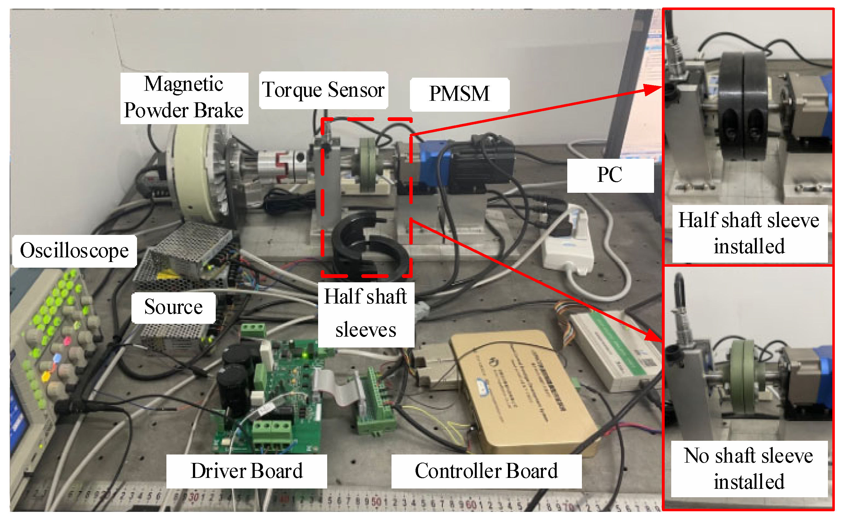
In order to verify the identification effect of the EGF-MRAS algorithm used in this paper, a PMSM control platform with an adjustable moment of inertia was built to identify the moment of inertia. The encoder is used to collect the motor speed. The adjustment of the PMSM moment of inertia is achieved by adding stainless-steel half shaft sleeves. The off-line algorithm has the characteristics of a high identification accuracy, and the off-line algorithm acceleration and deceleration method is introduced here. This method is used to measure the new moment of inertia of the motor after the stainless-steel half shaft sleeves is installed. The result can be used as the basis for judging the accuracy of the identification result.
The experiment uses one AC synchronous servo motor, several stainless-steel half shaft sleeves, 2500PPR incremental encoder, CSPACE, and the motor drive circuit board. CSPACE is a fast control prototype based on TMS320F28335DSP. It has AD, DA, IO, Encoder, PWM, and other simulation functions. After the control algorithm has been designed in MATLAB/Simulink, the DSP code can be generated and the corresponding control signals can be generated.
Figure 8 is the photo of the experimental platform. Table 5 shows the motor parameters for the experiment.
A set of simple experiments is used to verify the feasibility of the acceleration and deceleration algorithm. Moment of inertia of the experimental motor J = 6.30 × 10 4 ( kg · m 2 ) . The offline algorithm identification results are organized in Table 6.
The data in Table 7 are calculated using Equation (16):
J = T e · Δ t Δ ω .
The error between the calculated result of J ¯ and the actual value J r is less than 0.5%. The accuracy of this offline algorithm is proven. The standard values of the moments of inertia at each level after the addition of each group of the stainless-steel half shaft sleeves are calculated as the standard for the subsequent online identification experiment results.
Magnetic powder brakes are used to generate load torque.
The 2500CPR incremental encoder is used to calculate the speed of the motor. The encoder adopts a grating structure. The grating disc rotates synchronously with the motor shaft, with a loop of 4 × 2500 pulses. So, the calculation formula of speed is as follows:
n r = Q ( k ) Q ( k 7 ) 7 T × 4 × 2500 × 60 .
Among (17), n r is the actual speed of the motor in rpm. T is the sampling period. Q ( k ) is the number of encoder pulses collected at time k. In the experiment process, the set value of the speed loop can be modified by the computer in real time.

4.2. Design of the Experiment

The three identification algorithms are added into the controller. The identification performance of the three algorithms is analyzed by comparison experiment. The grouping method of the comparison experiment of the identification algorithm is shown in Table 8.
Firstly, the stability and velocity of the three algorithms are compared pairwise without external disturbance, and the accuracy parameters are calculated. Secondly, the speed disturbance is introduced to compare the anti-disturbance ability and the recovery ability of the three algorithms when the speed changes. Finally, the stability and velocity of the three algorithms are verified by adding a stainless steel sleeve to change the moment of inertia.

4.3. Experimental Results and Analysis

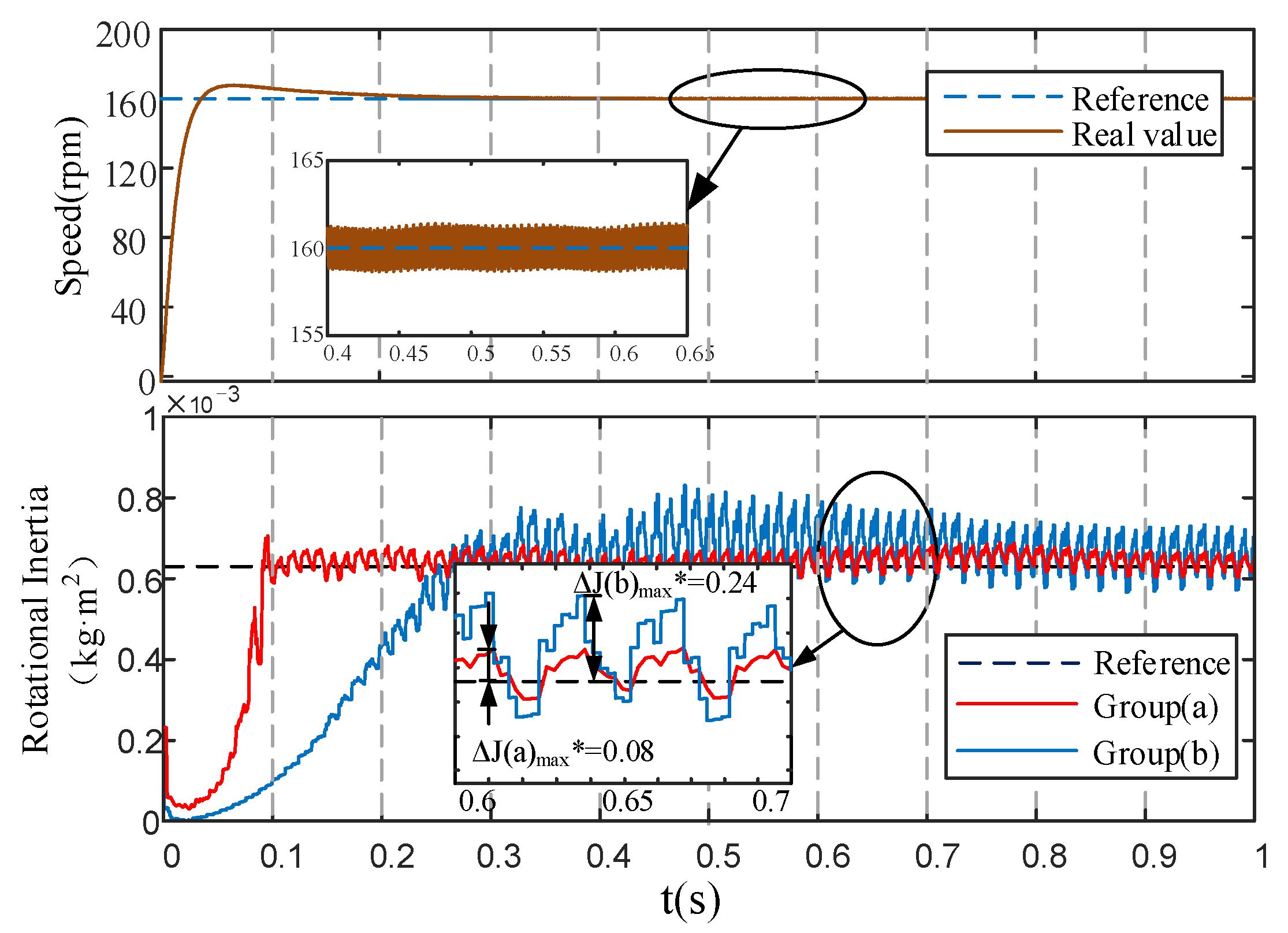
Experiment (i): Compare the EGF-MRAS algorithm (a) with the MRAS algorithm (b) under dynamic speed.
The standard value of the experimental motor’s moment of inertia is 6.3 × 10 4 ( kg · m 2 ) . In order to facilitate the calculation of the moment of inertia, the speed jitter is not completely filtered out. Figure 9 shows the identification results of the Algorithm (a) and Algorithm (b) experiments recorded from the start state of the motor. The calculation results of the accuracy parameters in Figure 9 are recorded in Table 9. In Figure 9, Δ J ( a ) m a x * = [ J ( a ) J ¯ ] J ¯ is defined.
From the experimental results in Figure 9 and the calculation results in Table 9, it can be seen that the overshoots of the two sets of experimental results are almost equal. However, a comparison of the calculation results of P β and P γ shows that EGF-MRAS algorithm is 6.9% higher than MRAS algorithm in terms of stability. The EGF-MRAS algorithm is 60.8% higher than MRAS algorithm in terms of identification speed. The starting stage of the motor is about 0.1 s. At the end of the starting stage the motor runs relatively smoothly, and the EGF-MRAS algorithm can quickly and accurately calculate the moment of inertia. So, EGF-MRAS algorithm has better stability and speed.
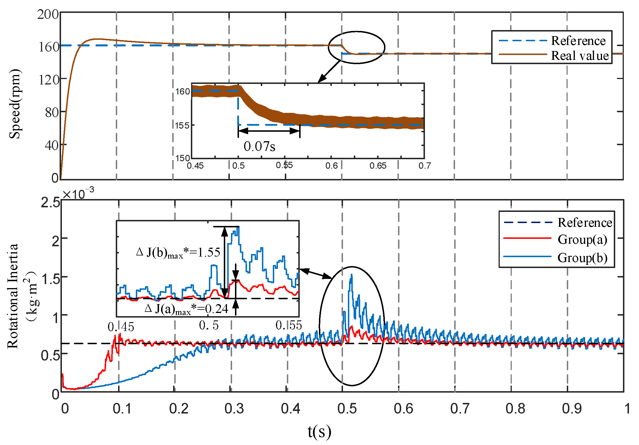
The most common fluctuation in the actual servo system is the speed disturbance. Therefore, the experiment of rotational speed disturbance was carried out. Under the condition of keeping the moment of inertia unchanged, experiments were carried out on the appearance of rotation speed disturbance, and the results are shown in Figure 10.
From the experimental results in Figure 10 and the calculation results in Table 10, it can be seen that MRAS algorithm is greatly affected by speed fluctuations.The overshoot of the EGF-MRAS algorithm is significantly lower than that of the MRAS algorithm. This means that the EGF-MRAS algorithm effectively suppresses the influence of the speed interference on the overshoot of the moment of the inertia identification result.
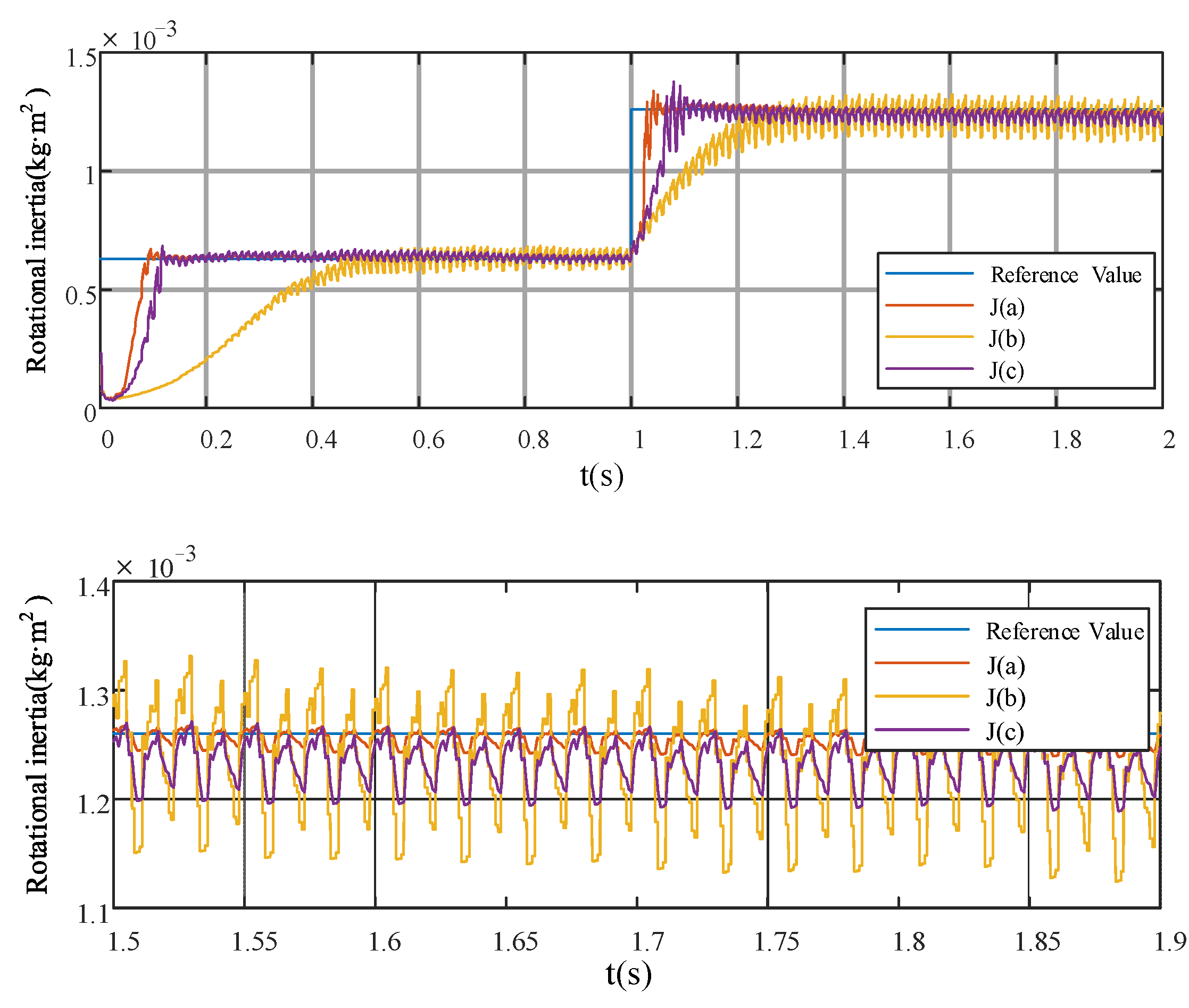
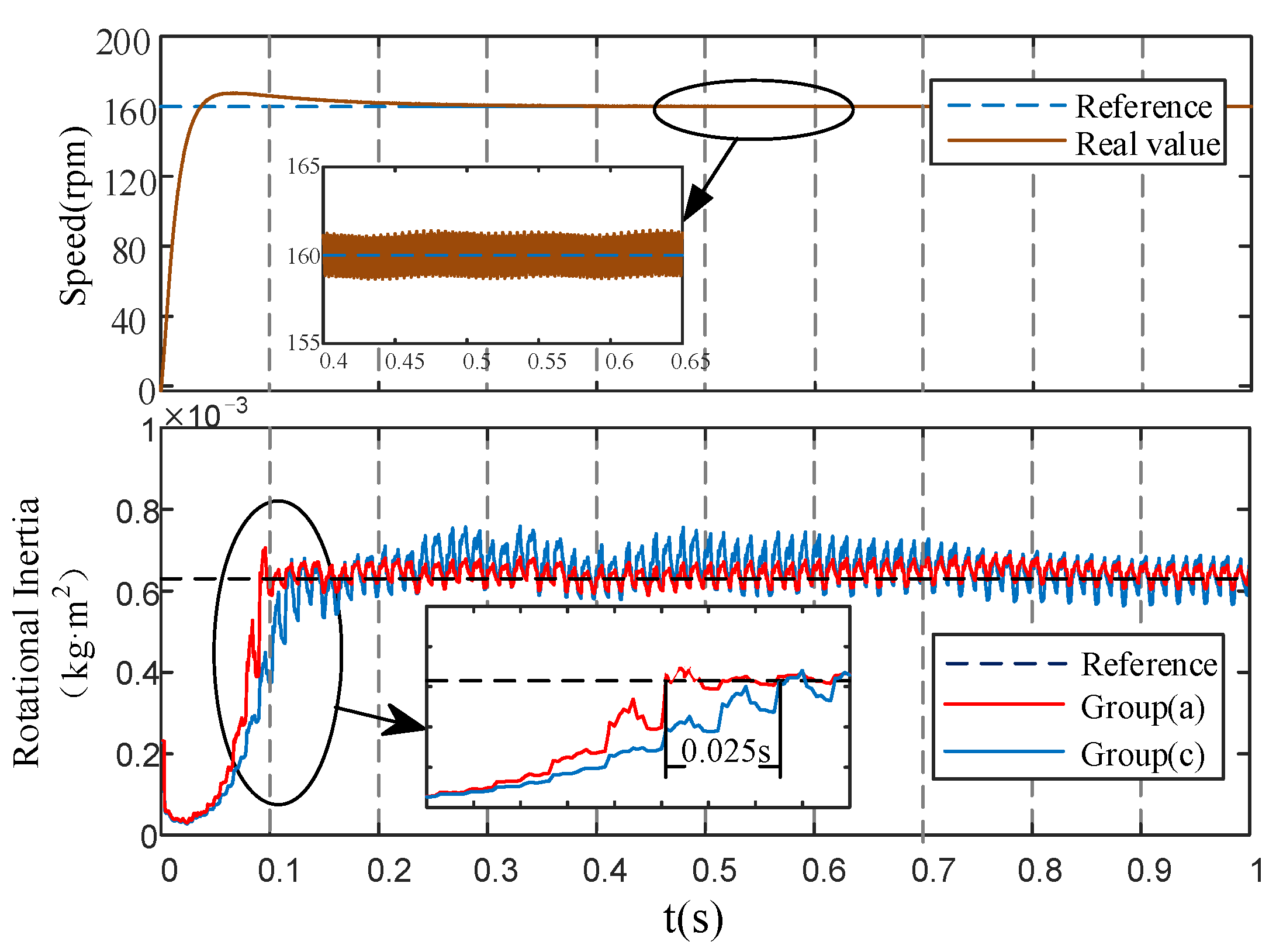
Experiment (ii): Compare the EGF-MRAS algorithm (a) with the error integrator adaptive algorithm (c) under dynamic speed.
The experimental results from the start state to the steady state of the motor are recorded in Figure 11.
From the experimental results in Figure 11 and the calculation results in Table 11, it can be seen that the overshoot of Algorithm (c) is slightly higher than Algorithm (a), which is about 2% higher. Algorithm (a) is 27.8% faster than that of Algorithm (c) in terms of the identification speed. Algorithm (a) is also 8.4% higher in stability than Algorithm (c). The comparison of the accuracy parameters P α , P β , and P γ shows that the dynamic performance of the EGF-MRAS algorithm is better than that of the difference integrator algorithm.
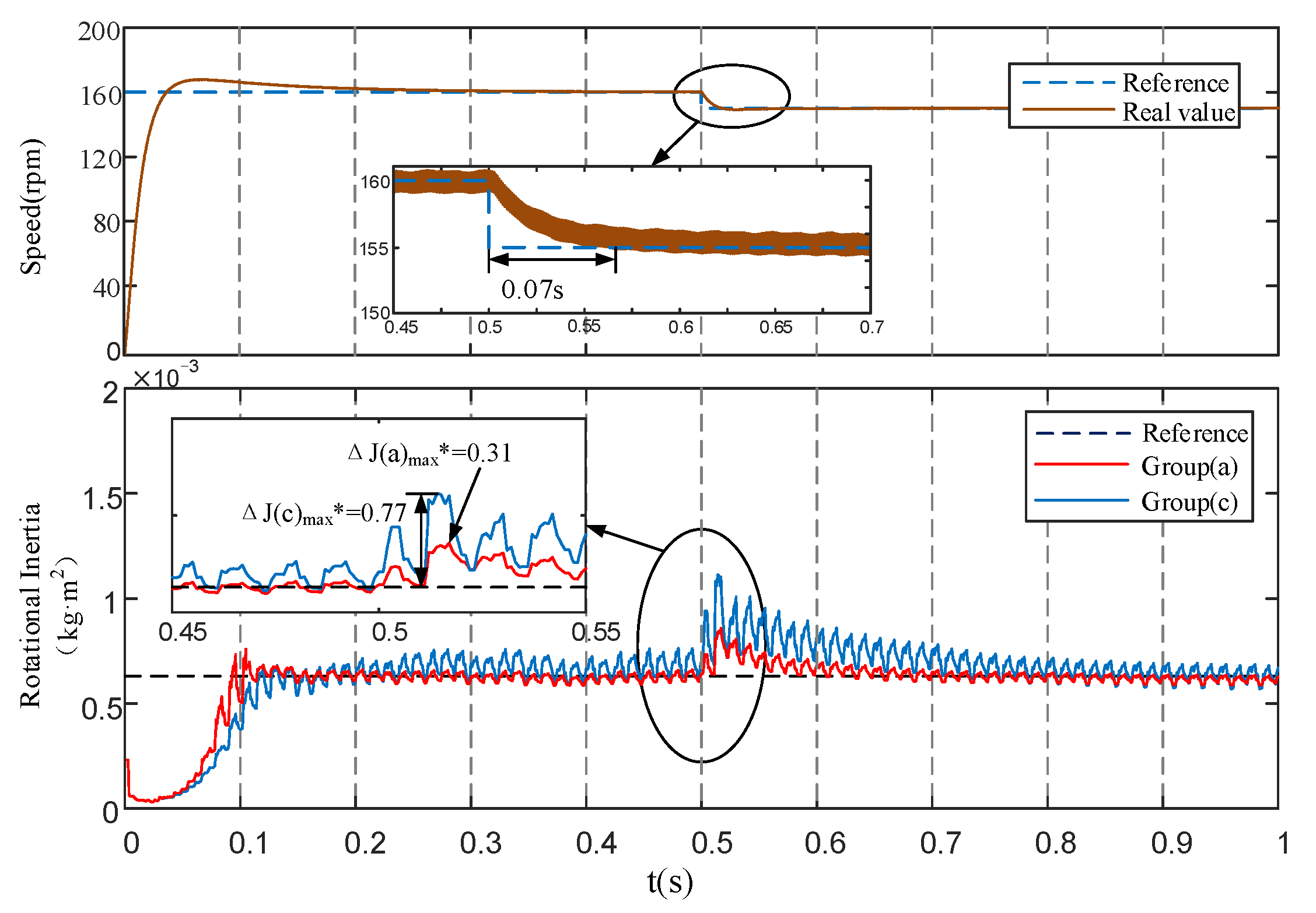
Figure 12 shows the experimental results of the appearance of the rotation speed interference while keeping the moment of inertia unchanged, and compares and analyzes the identification effect of the moment of inertia.
It can be seen from the experimental results that Algorithm (c) suppresses the interference caused by the speed disturbance to some extent, which is 33.9% higher than the algorithm (b) in Experiment (i). However, the suppression effect of Algorithm (a) is much better. Algorithm (a) is 46.3% higher than Algorithm (b) according to the accuracy parameters in Table 10 and Table 12. Therefore, among the three groups of algorithms, the EGF-MRAS algorithm has the strongest anti-interference performance.
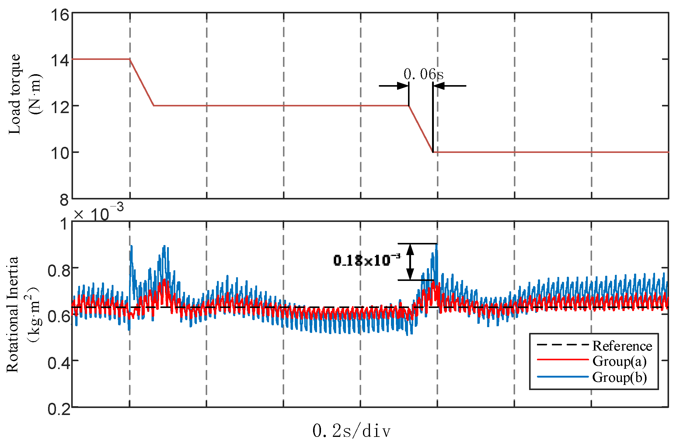
Experiment (iii): Verification experiment under dynamic load torque.
After the motor runs to steady state, the load torque is changed through the magnetic particle brake connected to the rotating shaft.
Figure 13 shows the identification results under dynamic load torque. It can be seen from the experimental results that P α ( a ) = 18.3% and P α ( b ) = 50.8%. Algorithm (a) has less errors and a faster recovery speed than Algorithm (b) under dynamic load torque. The identification accuracy of Algorithm (a) is also higher when the load torque tends to be stable. Therefore, the EGF-MRAS algorithm has better stability than the traditional MRAS algorithm.
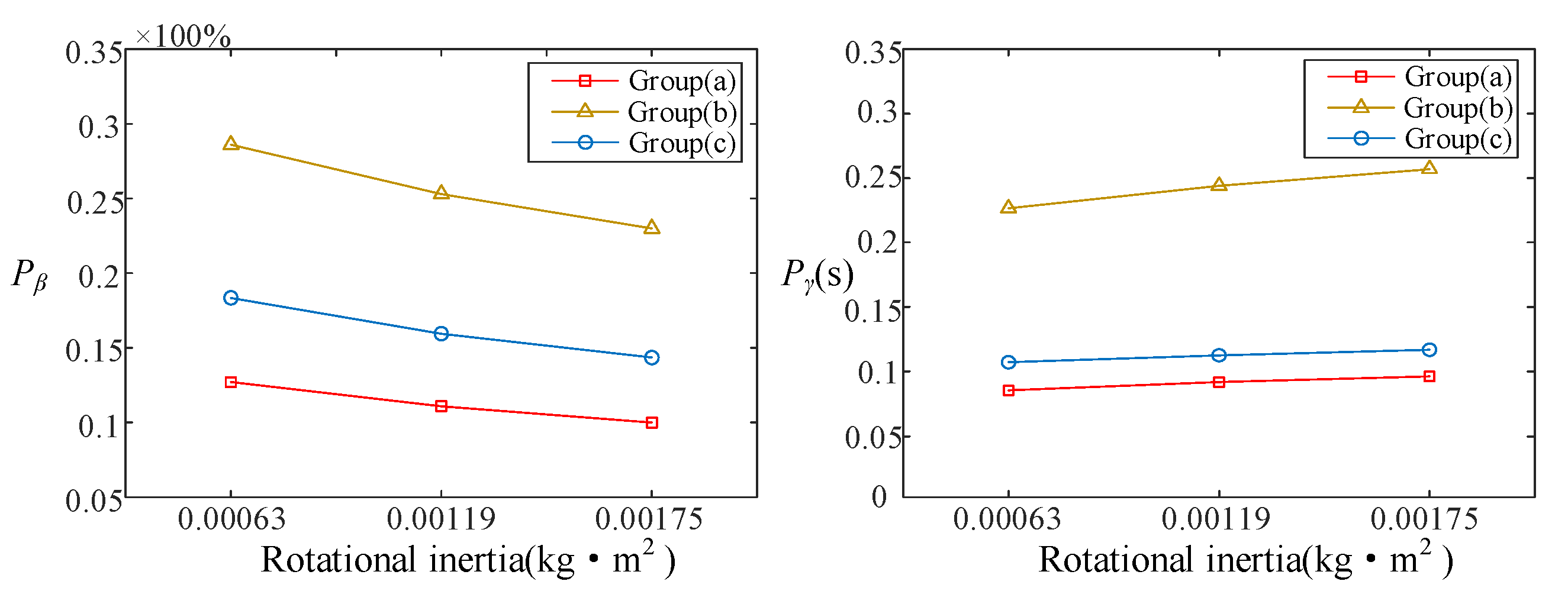
Experiment (iv): Verification experiment under different moment of inertia.
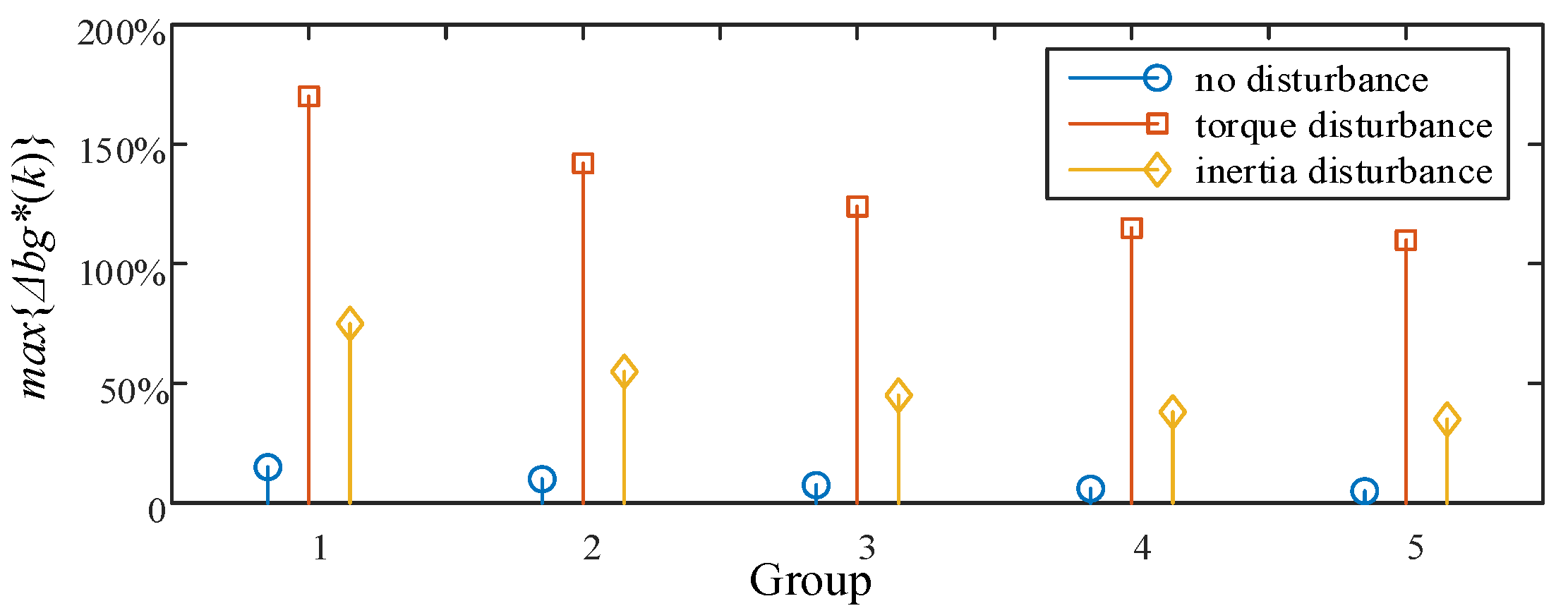
Figure 14 shows the calculation results of parameters P β and P γ under three different moments of inertia. The three abscissa values in the figure represent the standard value of the moments of inertia after 0, 1, and 2 groups of half shaft sleeves are installed on the motor shaft. It shows P β ( a ) < P β ( c ) < P β ( b ) , P γ ( a ) P γ ( c ) < P γ ( b ) . In the process of increasing the moment of inertia, the relationship between the accuracy parameters of each algorithm remains unchanged. This proves that the EGF-MRAS algorithm has a better dynamic performance under different working conditions.

5. Conclusions

In actual engineering, the identification effect of the moment of inertia of the servo motor has a great influence on the accuracy of its control system and on its other performances. Aiming at the shortcomings of the traditional MRAS identification algorithm in terms of stability and speed, this paper proposes an improved algorithm based on the error gain factor model. The calculation formula for the accuracy parameter is established. Through multiple sets of experimental analyses, the conclusions are as follows:
(1) The PMSM motion control model is established. Under the condition of the change of the moment of inertia, the relationship between the motor speed and the electromagnetic torque is obtained, and the PMSM’s moment of inertia identification model is established with the motor speed and the electromagnetic torque as the input parameters.
(2) The error gain factor is introduced to optimize the MRAS algorithm. Under dynamic conditions, the improved algorithm is compared with the two existing algorithms to verify the identification effect, which proves that the algorithm proposed in this paper has a higher speed, accuracy and stability.
(3) An experimental platform is set up to compare the identification results of the EGF-MRAS algorithm with the two existing algorithms under a variety of different working conditions. It is verified that the speed of the improved identification algorithm increased by about 55%, and the stability increased by 10–15% under dynamic speed. Under dynamic load torque conditions, the algorithm has a stronger anti-interference ability and higher accuracy. The EGF-MRAS algorithm effectively solves the problem of the poor anti-interference ability of the existing algorithm without reducing the identification accuracy, and improves the performance of the PMSM servo system.

Author Contributions

Conceptualization, F.X. and F.Y.; methodology, F.X. and F.Y.; software, F.X.; validation, F.X., F.Y. and C.A.; formal analysis, F.Y. and C.A.; investigation, F.X.; resources, F.X.; data curation, F.X. and F.Y.; writing—original draft preparation, F.X. and F.Y.; writing—review and editing, F.Y.; visualization, F.Y.; supervision, F.X.; project administration, F.X.; funding acquisition, F.X. All authors have read and agreed to the published version of the manuscript.

Funding

This research was funded by National Natural Science Foundation of China, grant number 51607002, Provincial Natural Science Foundation of Anhui in China, grant number 2108085ME179, National Natural Science Foundation of China, grant number 51637001.

Institutional Review Board Statement

Not applicable.

Informed Consent Statement

Not applicable.

Data Availability Statement

The data that support the findings of this study are available from the corresponding author upon requests.

Conflicts of Interest

The authors declare no conflict of interest.

References

  1. Hsu, C.-J.; Lai, Y.-S. Novel Online Optimal Bandwidth Search and Autotuning Techniques for Servo Motor Drives. IEEE Trans. Ind. Appl. 2017, 53, 3635–3642. [Google Scholar] [CrossRef]
  2. Huang, W.-S.; Liu, C.-W.; Hsu, P.-L.; Yeh, S.-S. Precision Control and Compensation of Servomotors and Machine Tools via the Disturbance Observer. IEEE Trans. Ind. Electron. 2009, 57, 420–429. [Google Scholar] [CrossRef]
  3. Kim, S. Moment of Inertia and Friction Torque Coefficient Identification in a Servo Drive System. IEEE Trans. Ind. Electron. 2019, 66, 60–70. [Google Scholar] [CrossRef]
  4. Choi, J.-W.; Lee, S.-C.; Kim, H.-G. Inertia identification algorithm for high-performance speed control of electric motors. IEE Proc.-Electr. Power Appl. 2006, 153, 379–386. [Google Scholar] [CrossRef]
  5. Fujita, K.; Sado, K. Instantaneous speed detection with parameter identification for AC servo systems. IEEE Trans. Ind. Appl. 1992, 28, 864–872. [Google Scholar] [CrossRef]
  6. Chen, Y.; Yang, M.; Long, J.; Qu, W.; Xu, D.; Blaabjerg, F. A Moderate Online Servo Controller Parameter Self-Tuning Method via Variable-Period Inertia Identification. IEEE Trans. Power Electron. 2019, 34, 12165–12180. [Google Scholar] [CrossRef]
  7. Wang, P.; Lin, K.; Lin, M.; Yang, A.; Fu, F.; Ai, J. Online multi-parameter estimation of permanent magnet synchronous machine with step-pulse injection. IET Electr. Power Appl. 2021, 15, 186–199. [Google Scholar] [CrossRef]
  8. Liu, K.; Hou, C.; Hua, W. A Novel Inertia Identification Method and Its Application in PI Controllers of PMSM Drives. IEEE Access 2019, 7, 13445–13454. [Google Scholar] [CrossRef]
  9. Campos-Delgado, D.U.; Arce-Santana, E.R.; Espinoza-Trejo, D.R. Edge optimisation for parameter identification of induction motors. IET Electr. Power Appl. 2011, 5, 668–675. [Google Scholar] [CrossRef]
  10. Andoh, F. Moment of Inertia Identification Using the Time Average of the Product of Torque Reference Input and Motor Position. IEEE Trans. Power Electron. 2007, 22, 2534–2542. [Google Scholar] [CrossRef]
  11. Lin, F.-J.; Chen, S.-G.; Li, S.; Chou, H.-T.; Lin, J.-R. Online Autotuning Technique for IPMSM Servo Drive by Intelligent Identification of Moment of Inertia. IEEE Trans. Ind. Inform. 2020, 16, 7579–7590. [Google Scholar] [CrossRef]
  12. Wang, S.; Dinavahi, V.; Xiao, J. Multi-rate real-time model-based parameter estimation and state identification for induction motors. IET Electr. Power Appl. 2013, 7, 77–86. [Google Scholar] [CrossRef]
  13. Li, S.; Liu, Z. Adaptive Speed Control for Permanent-Magnet Synchronous Motor System with Variations of Load Inertia. IEEE Trans. Ind. Electron. 2009, 56, 3050–3059. [Google Scholar]
  14. Zhang, J.; Xu, H. Online Identification of Power System Equivalent Inertia Constant. IEEE Trans. Ind. Electron. 2017, 64, 8098–8107. [Google Scholar] [CrossRef]
  15. Lee, K.; Ahmed, S.; Lukic, S.M. Universal Restart Strategy for High-Inertia Scalar-Controlled PMSM Drives. IEEE Trans. Ind. Appl. 2016, 52, 4001–4009. [Google Scholar] [CrossRef]
  16. Chen, J.; Huang, J. Alternative Solution Regarding Problems of Adaptive Observer Compensating Parameters Uncertainties for Sensorless Induction Motor Drives. IEEE Trans. Ind. Electron. 2019, 67, 5879–5888. [Google Scholar] [CrossRef]
  17. Lee, K.; Ahmed, S.; Lukic, S.M. Restart Strategy for Scalar (V/f) Controlled Synchronous Reluctance Machine Driving a High-Inertia Load. IEEE Trans. Ind. Appl. 2019, 55, 3834–3841. [Google Scholar] [CrossRef]
  18. Nguyen, A.T.; Rafaq, M.S.; Choi, H.H.; Jung, J.-W. A Model Reference Adaptive Control Based Speed Controller for a Surface-Mounted Permanent Magnet Synchronous Motor Drive. IEEE Trans. Ind. Electron. 2018, 65, 9399–9409. [Google Scholar] [CrossRef]
  19. Wang, D.-Q.; Liu, H.-B.; Ding, F. Fuzzy Least Squares for Identification of Individual Pharmacokinetic Parameters. IEEE Trans. Biomed. Eng. 2009, 23, 2796–2805. [Google Scholar]
  20. Song, Z.; Mei, X.; Jiang, G. Inertia identification based on model reference adaptive system with variable gain for AC servo systems. In Proceedings of the 2017 IEEE International Conference on Mechatronics and Automation (ICMA), Takamatsu, Japan, 6–9 August 2017; pp. 188–192. [Google Scholar]
  21. Lian, C.; Xiao, F.; Gao, S.; Liu, J. Load Torque and Moment of Inertia Identification for Permanent Magnet Synchronous Motor Drives Based on Sliding Mode Observer. IEEE Trans. Power Electron. 2019, 34, 5675–5683. [Google Scholar] [CrossRef]
  22. Li, S.; Gu, H. Fuzzy Adaptive Internal Model Control Schemes for PMSM Speed-Regulation System. IEEE Trans. Ind. Inform. 2012, 8, 767–779. [Google Scholar] [CrossRef]
  23. Lee, K.B.; Yoo, J.Y.; Song, J.H.; Choy, I. Improvement of low speed operation of electric machine with an inertia identification using ROELO. IEE Proc.-Electr. Power Appl. 2003, 151, 116–120. [Google Scholar] [CrossRef]
  24. Kim, H.; Kim, H.; Choi, J. Multiparameter identification for SPMSMs using NLMS adaptive filters and extended sliding-mode observer. IET Electr. Power Appl. 2020, 14, 533–543. [Google Scholar] [CrossRef]
Figure 1. The tendency of torque and speed.
Energies 14 06664 g001
Figure 2. The closed loop control system of PMSM.
Energies 14 06664 g002
Figure 3. Block diagram of MRAS.
Energies 14 06664 g003
Figure 4. The tendency of parameter   b g ( k ) .
Energies 14 06664 g004
Figure 5. Experimental results of the different disturbance types.
Energies 14 06664 g005
Figure 6. Work flow chart of the error gain factor module.
Energies 14 06664 g006
Figure 7. Simulation results of group (a), group (b), and group (c).
Energies 14 06664 g007
Figure 8. Experiment platform.
Energies 14 06664 g008
Figure 9. Steady-state identification results of Experiment (i).
Energies 14 06664 g009
Figure 10. Speed interference identification results of Experiment (i).
Energies 14 06664 g010
Figure 11. Steady-state identification results of Experiment (ii).
Energies 14 06664 g011
Figure 12. Speed interference identification results of Experiment (ii).
Energies 14 06664 g012
Figure 13. Identification results of Experiment (iii).
Energies 14 06664 g013
Figure 14. Comparison of the parameters P β and P γ under different inertia.
Energies 14 06664 g014
Table 1. Grouping of simulation.
Group12345
J   ( kg · m 2 )0.00030.00060.00090.00120.0015
Table 2. Parameter settings of the PMSM model.
ParameterValue
Number of phases3
Pole pairs2
Back EMF waveformSinusoidal
Rotor typeRound
Mechanical input 1Torque TL
Mechanical input 2Inertia J
Stator phase resistance/(ohm)0.8
Armature inductance/(H)3.95 × 10−4
Flux linkage/(Wb)0.1852
Table 3. Simulation groups of algorithms.
GroupAlgorithm
(a)EGF-MRAS algorithm
(b)MRAS algorithm
(c)Error integrator adaptive algorithm
Table 4. Calculation results of the accuracy parameters.
Groups P α P β P γ
a6.6%2.9%0.025 s
b-13.7%0.179 s
c7.2%6.6%0.062 s
Table 5. Parameters of the PMSM.
ParameterValue
motor typeASM200-36-1250/2500
Excitation modePermanent magnet
Number of Pole Pairs4
Line resistance0.33 Ω
Line inductance0.9 mH
Rated voltage36 V
Rated torque1.276 N·m
Rated current7.5 A
Maximum speed3000 rpm
Motor weight1.1 kg
Table 6. Acceleration and deceleration method measurement results.
ω (rad/s) 08208200
t (s)00.05211.051
Table 7. Comparison of the calculation results.
Groups J a J d J ¯ J r
J   ( × 10 4   kg · m 2 )6.346.246.296.30
Table 8. Experiment groups of algorithms.
GroupAlgorithm
(a)EGF-MRAS algorithm
(b)MRAS algorithm
(c)Error integrator adaptive algorithm
Table 9. Calculation results of the accuracy parameters of Figure 9.
Groups P α P β P γ
(a)15.6%12.7%0.090 s
(b)16.0%19.6%0.239 s
Table 10. Calculation results of the accuracy parameters of Figure 10.
Groups P α P β
(a)31.0%12.7%
(b)128.7%28.6%
Table 11. Calculation results of the accuracy parameters of Figure 11.
Groups P α P β P γ
(a)15.4%12.7%0.090 s
(c)17.2%21.1%0.115 s
Table 12. Calculation results of the accuracy parameters of Figure 12.
Groups P α P β
(a)31.0%12.7%
(c)77.3%21.1%
Publisher’s Note: MDPI stays neutral with regard to jurisdictional claims in published maps and institutional affiliations.

