
Pressure Retarded Osmosis Power Units Modelling for Power Flow Analysis of Electric Distribution Networks


 ,
,
Abstract
:1. Introduction
2. Models of Distribution Network Conventional Components
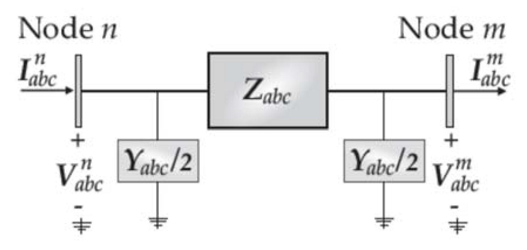
2.1. Modelling of Conventional Series Components
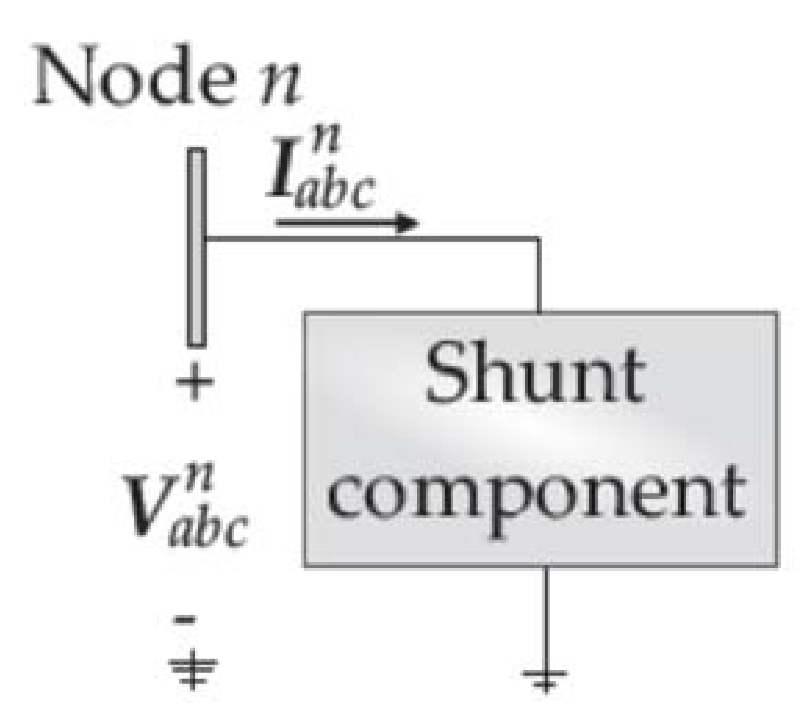
2.2. Modelling of Conventional Shunt Components
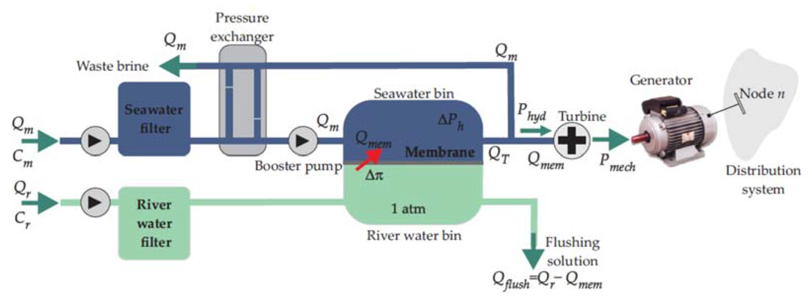
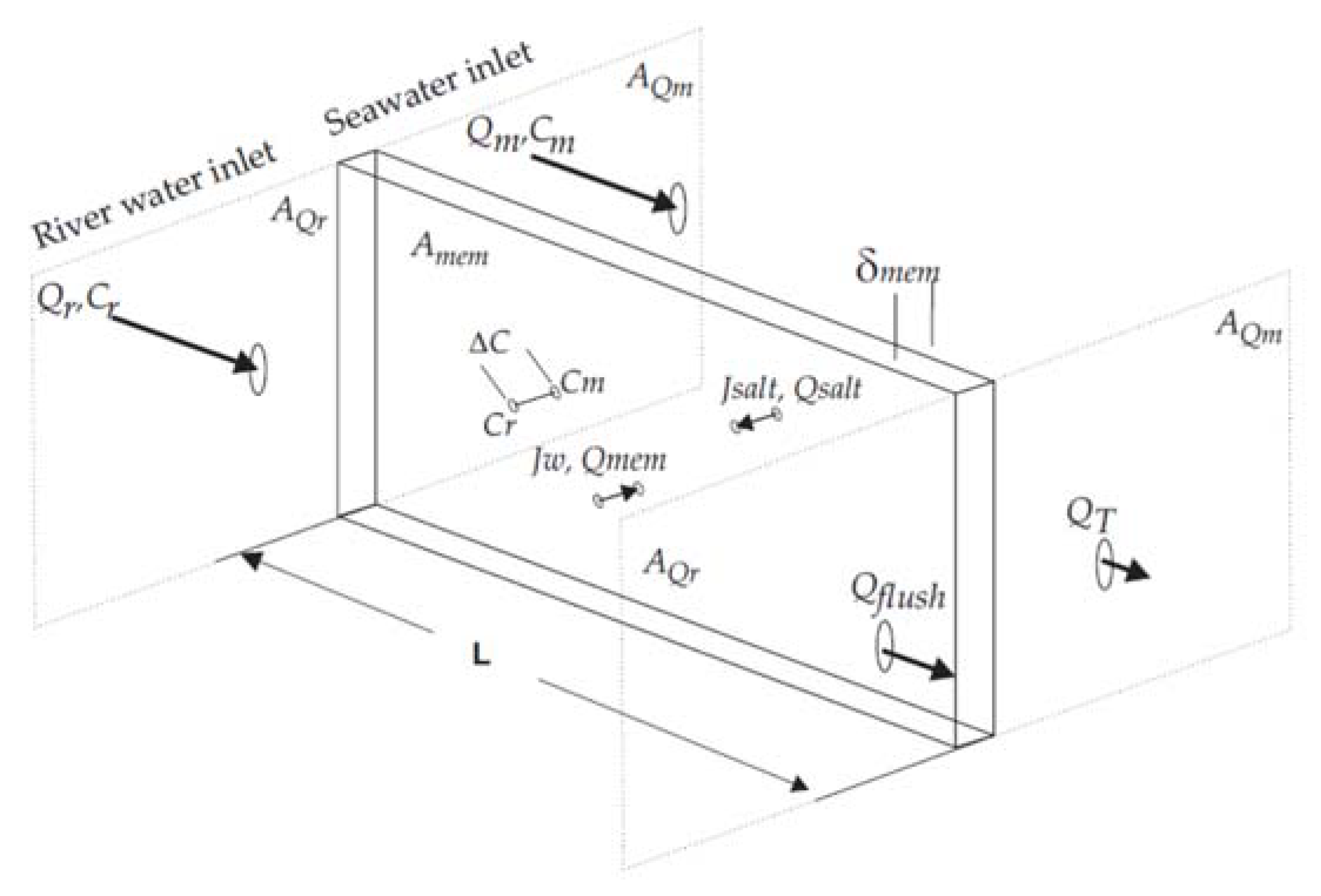
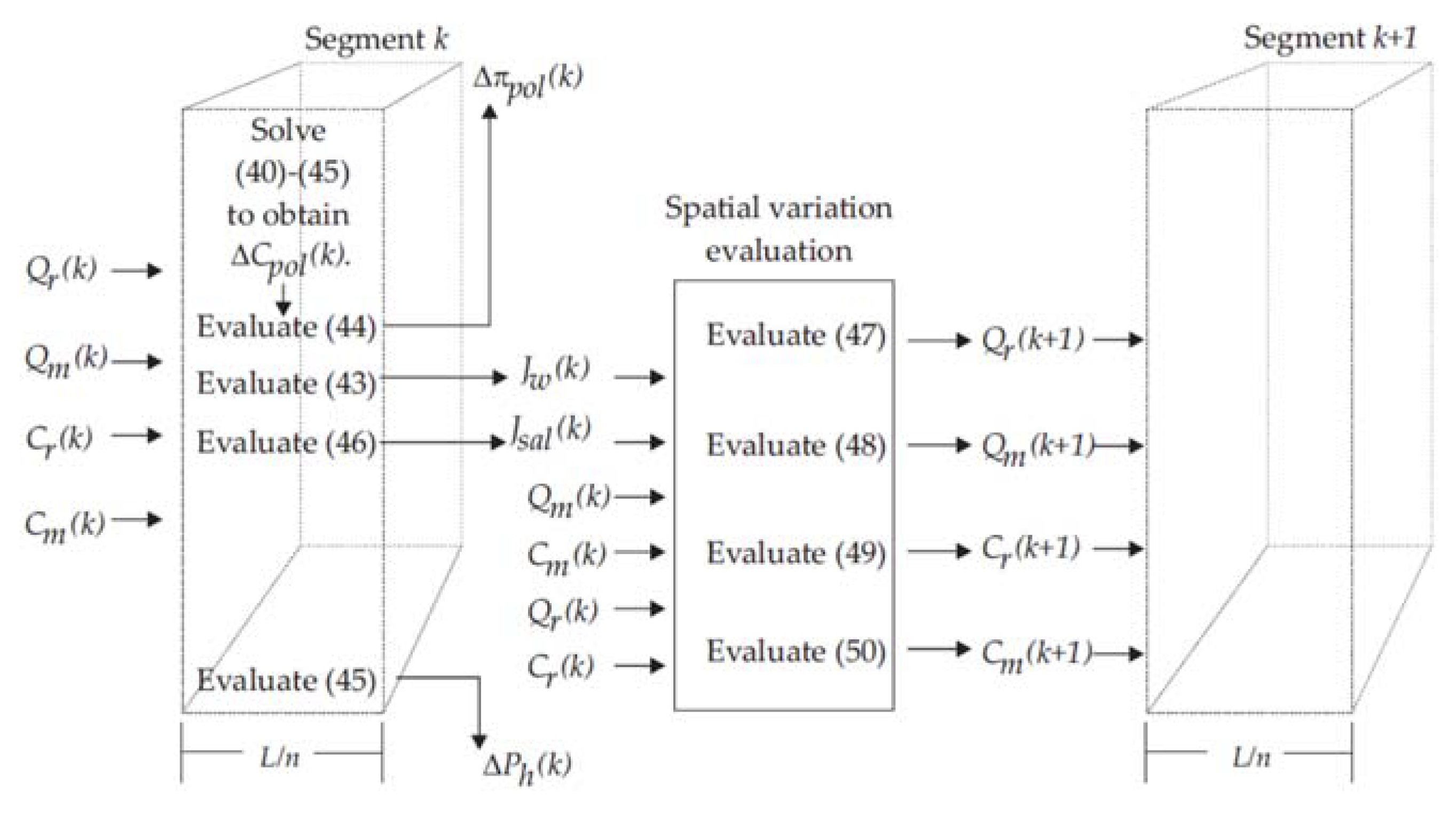
3. Modelling of PRO Power Units
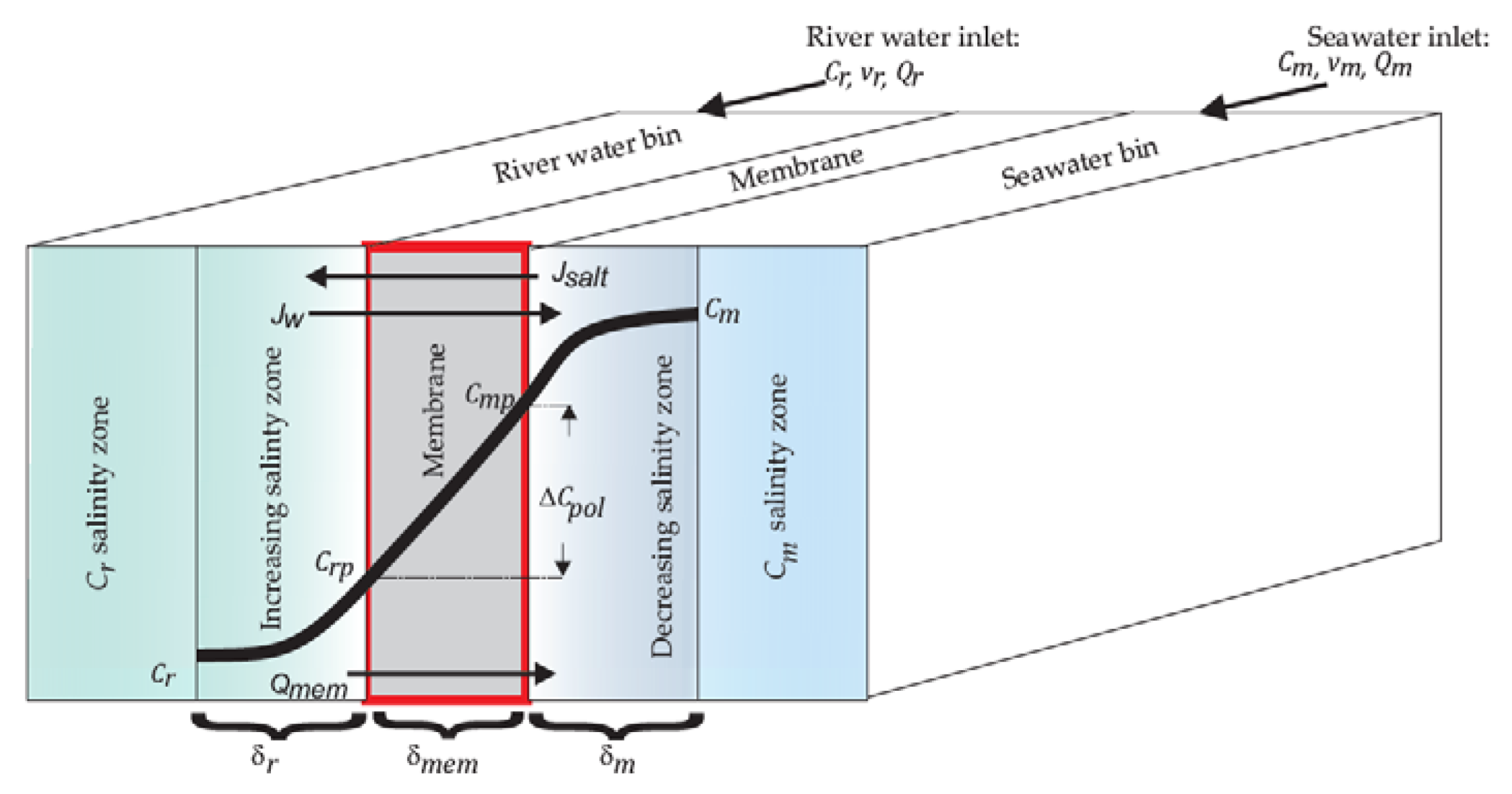
3.1. Model of the Harvested Hydraulic Power
3.2. Model of the Mechanical Power Produced by the Turbine
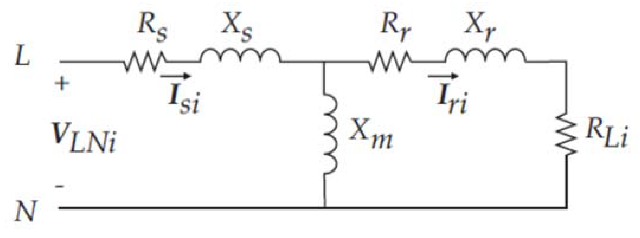
3.3. Model of the Electric Generator
4. Forward-Backward Sweep Method for Power Flow Analysis
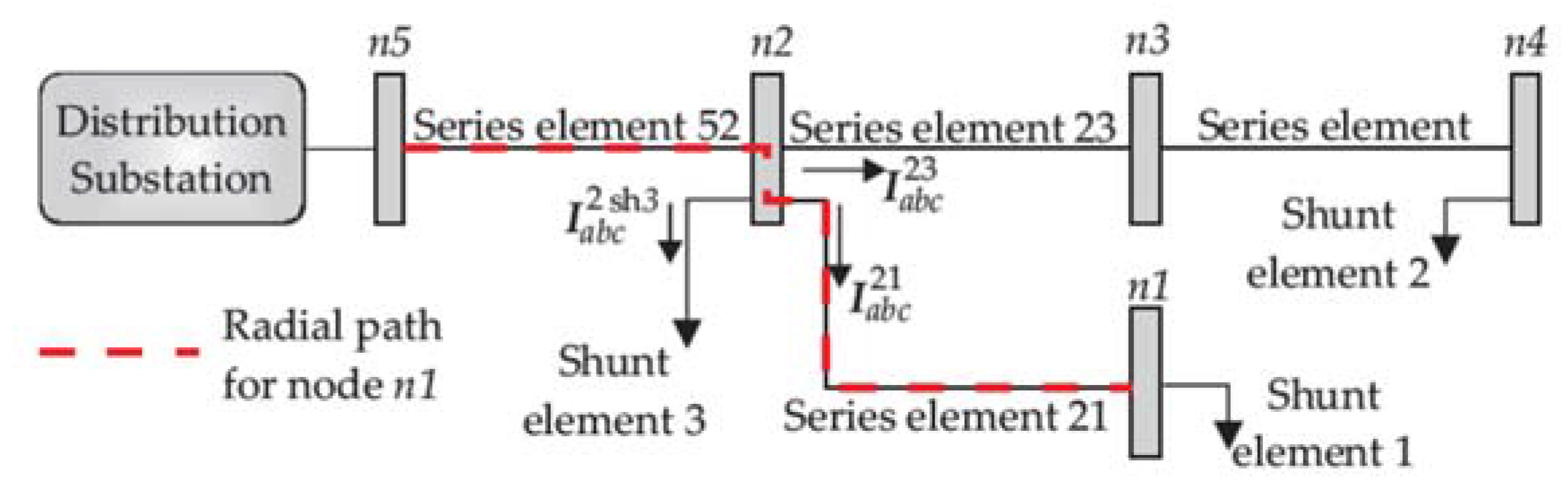
4.1. Preliminaries of the FBS Method
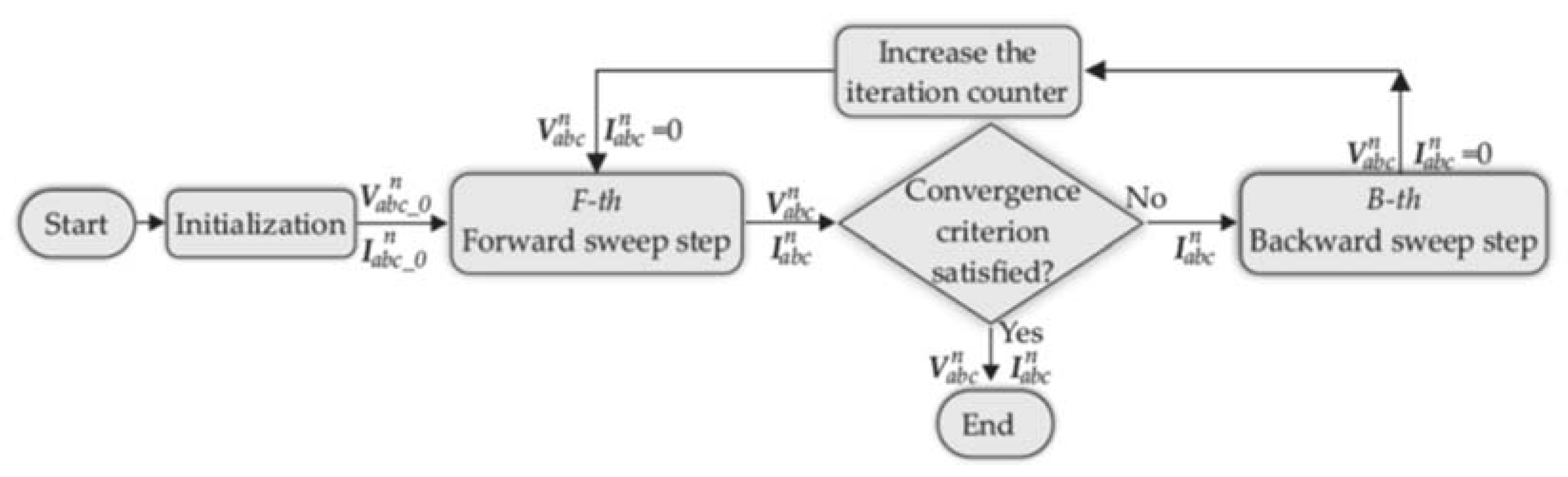
4.2. The FBS Method
4.3. Forward Sweep Sub-Step
4.4. Backward Sweep Sub-Step
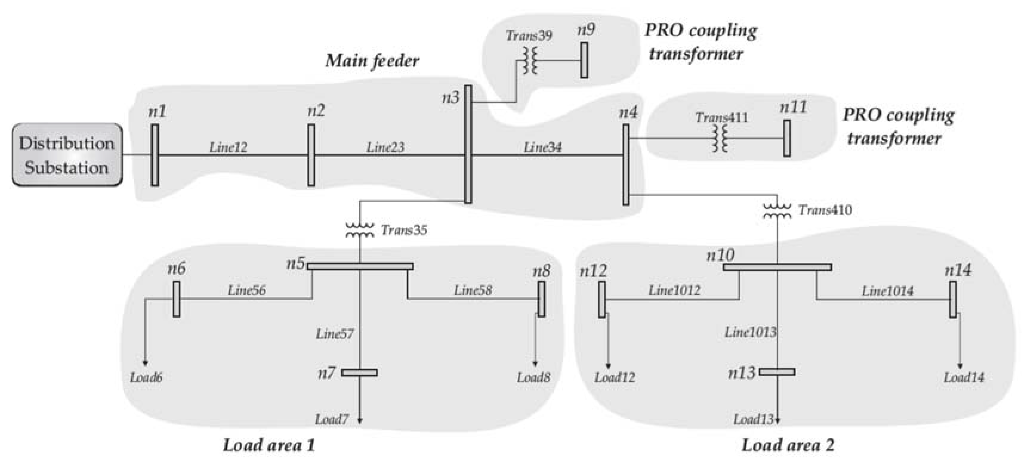
5. Numerical Results
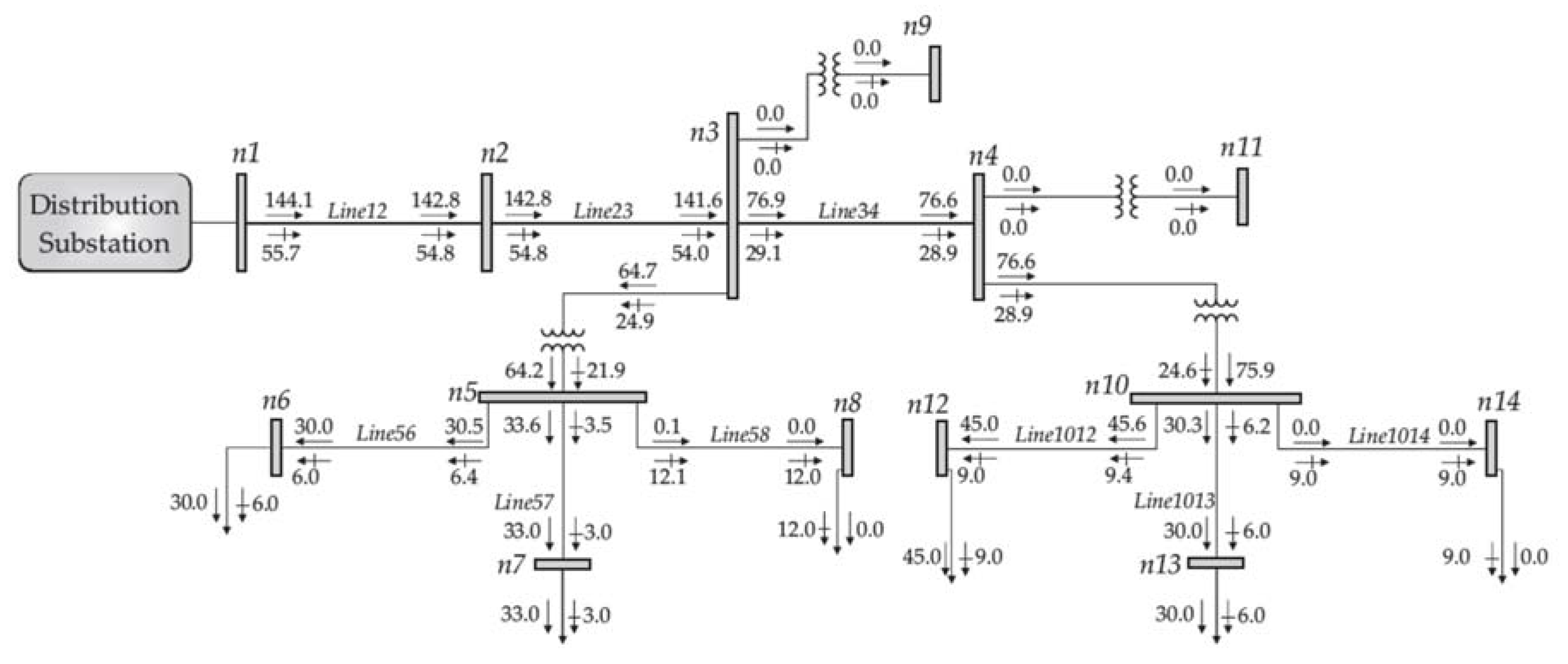
5.1. Steady-State Operating Condition for the Base Case
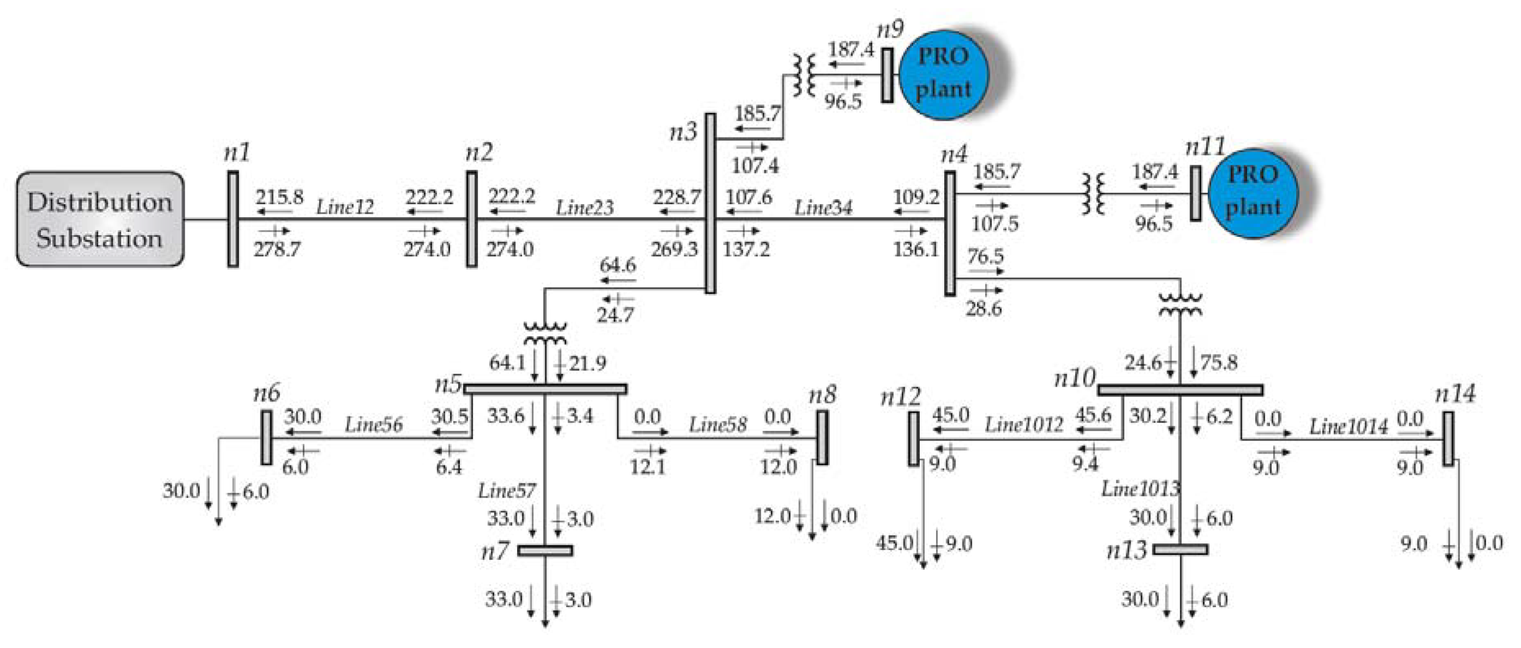
5.2. Steady-State Operating Conditions Considering the Integration of PRO Power Plants
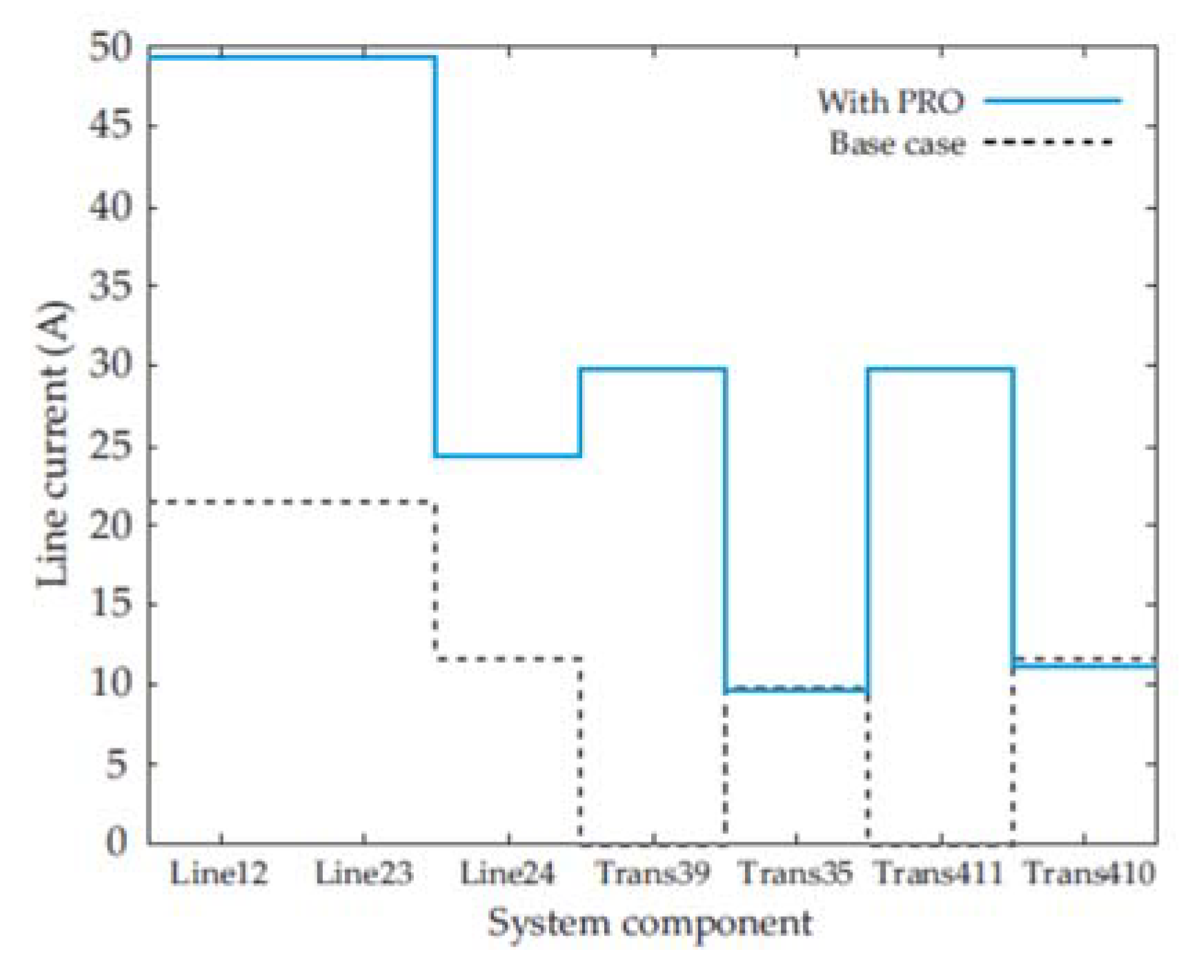
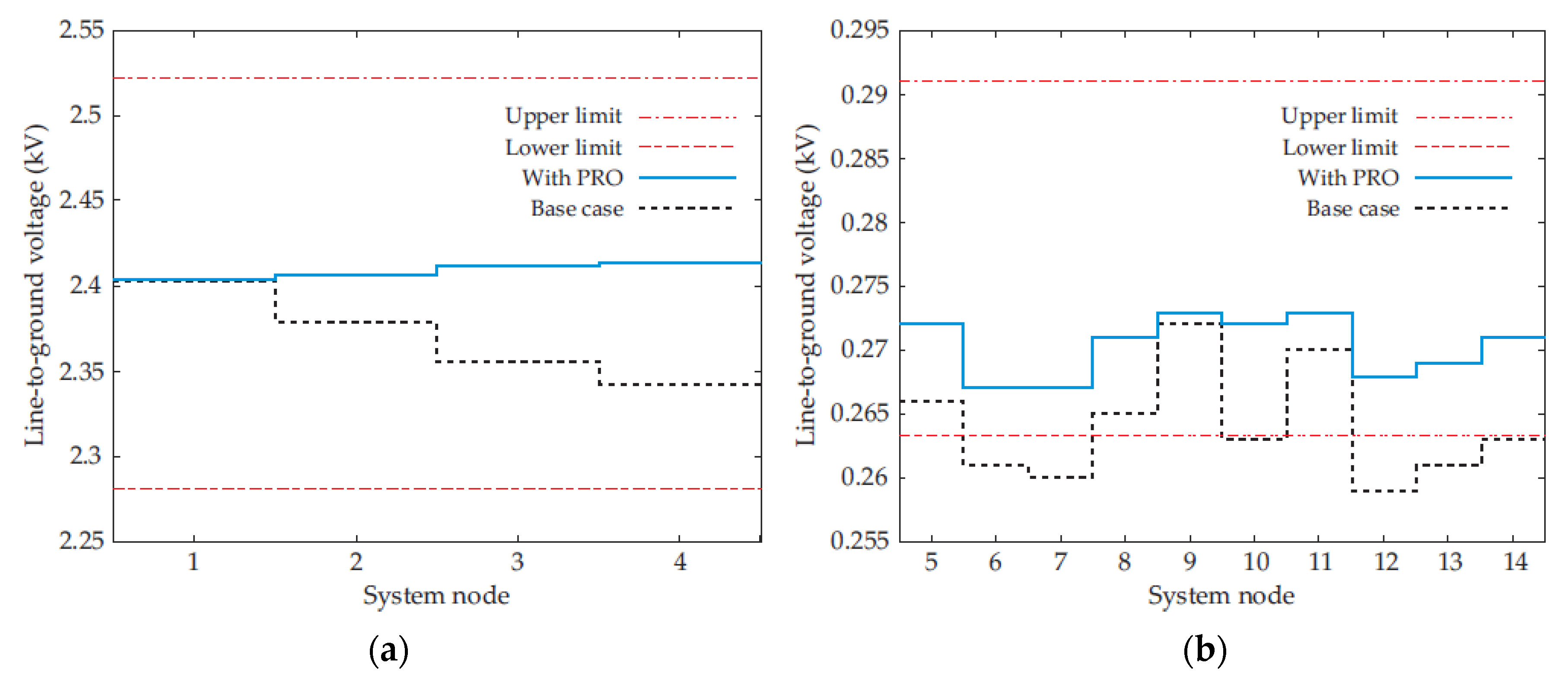
5.3. Comparison of the Steady-State Operating Conditions
6. Conclusions
Author Contributions
Funding
Acknowledgments
Conflicts of Interest
Appendix A
Appendix A.1. Distribution Line Segments

| Line Segment | Node n | Node m | Length (miles) |
|---|---|---|---|
| Line12 | n1 | n2 | 0.8 |
| Line23 | n2 | n3 | 0.8 |
| Line34 | n3 | n4 | 0.8 |
| Line56 | n5 | n6 | 0.1 |
| Line57 | n5 | n7 | 0.1 |
| Line58 | n5 | n8 | 0.1 |
| Line1012 | n10 | n12 | 0.05 |
| Line1013 | n10 | n13 | 0.05 |
| Line1014 | n10 | n14 | 0.05 |
Appendix A.2. PRO Coupling and Supply Transformers
| Transformer | Node n | Node m | Rated Power (kVA) | Rated High Side Voltage (kV) | Rated Low Side Voltage (kV) | Resistance (%) | Reactance (%) |
|---|---|---|---|---|---|---|---|
| Trans39 | n3 | n9 | 250 | 4.16 | 0.48 | 1 | 6 |
| Trans35 | n3 | n5 | 100 | 4.16 | 0.48 | 1 | 6 |
| Trans411 | n4 | n11 | 250 | 4.16 | 0.48 | 1 | 6 |
| Trans410 | n4 | n10 | 100 | 4.16 | 0.48 | 1 | 6 |
Appendix A.3. System Power Loads
| Load | Node n | Rated Voltage (kV) | Phase a Power | Phase b Power | Phase c Power | |||
|---|---|---|---|---|---|---|---|---|
| Active (kW) | Reactive (kVAR) | Active (kW) | Reactive (kVAR) | Active (kW) | Reactive (kVAR) | |||
| Load6 | n6 | 0.48 | 10 | 2 | 10 | 2 | 10 | 2 |
| Load7 | n7 | 0.48 | 11 | 1 | 11 | 1 | 11 | 1 |
| Load8 | n8 | 0.48 | 0 | 4 | 0 | 4 | 0 | 4 |
| Load12 | n12 | 0.48 | 15 | 3 | 15 | 3 | 15 | 3 |
| Load13 | n13 | 0.48 | 10 | 2 | 10 | 2 | 10 | 2 |
| Load14 | n14 | 0.48 | 0 | 3 | 0 | 3 | 0 | 3 |
Appendix A.4. PRO Power Unit
| Name | Symbol | Value |
|---|---|---|
| Water permeability | A | 1.87 × 10⁻⁹ m/(s kPa) |
| Salt permeability | B | 1.11 × 10⁻⁷ m/s |
| Structural parameter | S | 6.78 × 10⁻⁴ m |
| Surface area | Amem | 222 m2 |
| Membrane length | L | 1.52 m |
| Salt diffusion coefficient for the river water side | Dr | 1.4285 × 10⁻⁹ m2/s |
| Salt diffusion coefficient for the sea water side | Dm | 1.4350 × 10⁻⁹ m2/s |
| River water side boundary layer thicknesses | δr | 3.0710 × 10⁻⁵ m |
| Seawater side boundary layer thicknesses | δm | 3.1014 × 10⁻⁵ m |
| Membrane segmentation for spatial variation | n | 165 segments |
| Name | Symbol | Value |
|---|---|---|
| Temperature | T | 297.15 K |
| River water concentration | Cr | 0 g/L |
| Seawater concentration | Cm | 35 g/L |
| River water flow rate | Qr | 0.0012 m3/s |
| Seawater flow rate | Qm | 0.0011 m3/s |
| River water density | ρr | 1000 kg/m3 |
| Seawater density | ρm | 1027 kg/m3 |
| Name | Symbol | Value |
|---|---|---|
| Pumping element efficiencies | ηrps, ηmps, ηbp | 100% |
| Exchanger efficiency | ηpx | 100% |
| Pipeline pressure losses | Prpu, Pmpu, Pmd | 0 kPa |
| Turbine efficiency | ηTurb | 85% |
| Name | Symbol | Value |
|---|---|---|
| Rated power | Prated | 10 HP |
| Rated voltage | Vrated | 480 V |
| Stator resistance | Rs | 0.740 (Ω) |
| Stator reactance | Xs | 1.33 (Ω) |
| Rotor resistance | Rr | 0.647 (Ω) |
| Rotor reactance | Xr | 2.01 (Ω) |
| Magnetization reactance | Xm | 77.6 (Ω) |
References
- Mofor, L.; Goldsmith, J.; Jones, F. Ocean Energy: Techmology Readiness, Patents, Deployment Status and Outlook. 2014. Available online: https://www.irena.org/-/media/Files/IRENA/Agency/Publication/2014/IRENA_Ocean_Energy_report_2014.pdf (accessed on 21 August 2021).
- Touati, K.; Tadeo, F.; Chae, S.H.; Kim, J.H.; Alvarez-Silva, O. Pressure Retarded Osmosis: Renewable Energy Generation and Recovery, 1st ed.; Academic Press: Cambridge, MA, USA, 2017; ISBN 978-0-12-812103-0. [Google Scholar]
- Reyes-Mendoza, O.; Alvarez-Silva, O.; Chiappa-Carrara, X.; Enriquez, C. Variability of the thermohaline structure of a coastal hypersaline lagoon and the implications for salinity gradient energy harvesting. Sustain. Energy Technol. Assess. 2020, 38, 100645. [Google Scholar] [CrossRef]
- Straub, A.P.; Deshmukh, A.; Elimelech, M. Pressure-retarded osmosis for power generation from salinity gradients: Is it viable? Energy Environ. Sci. 2016, 9, 31–48. [Google Scholar] [CrossRef]
- Kempener, R.; Neumann, F. Salinity Gradient Energy Technology Brief. 2014. Available online: https://www.irena.org/-/media/Files/IRENA/Agency/Publication/2014/Jun/Salinity_Energy_v4_WEB.pdf (accessed on 21 August 2021).
- Lee, C.; Chae, S.H.; Yang, E.; Kim, S.; Kim, J.H.; Kim, I.S. A comprehensive review of the feasibility of pressure retarded osmosis: Recent technological advances and industrial efforts towards commercialization. Desalination 2020, 491, 114501. [Google Scholar] [CrossRef]
- Tran, T.T.D.; Bianchi, C.; Melville, J.; Park, K.K.; Smith, A.D. Design of housing and mesh spacer supports for salinity gradient hydroelectric power generation using pressure retarded osmosis. In Proceedings of the 2015 IEEE Conference on Technologies for Sustainability (SusTech), Ogden, UT, USA, 30 July–1 August 2015; pp. 141–147. [Google Scholar]
- Kurihara, M.; Sakai, H.; Tanioka, A.; Tomioka, H. Role of pressure-retarded osmosis (PRO) in the mega-ton water project. Desalin. Water Treat. 2016, 57, 26518–26528. [Google Scholar] [CrossRef]
- Matsuyama, K.; Makabe, R.; Ueyama, T.; Sakai, H.; Saito, K.; Okumura, T.; Hayashi, H.; Tanioka, A. Power generation system based on pressure retarded osmosis with a commercially-available hollow fiber PRO membrane module using seawater and freshwater. Desalination 2021, 499, 114805. [Google Scholar] [CrossRef]
- Ackermann, T.; Andersson, G.; Söder, L. Distributed generation: A definition. Electr. Power Syst. Res. 2001, 57, 195–204. [Google Scholar] [CrossRef]
- Shayani, R.A.; de Oliveira, M.A.G. Photovoltaic Generation Penetration Limits in Radial Distribution Systems. IEEE Trans. Power Syst. 2011, 26, 1625–1631. [Google Scholar] [CrossRef]
- Jain, S.; Kalambe, S.; Agnihotri, G.; Mishra, A. Distributed generation deployment: State-of-the-art of distribution system planning in sustainable era. Renew. Sustain. Energy Rev. 2017, 77, 363–385. [Google Scholar] [CrossRef]
- Hung, D.Q.; Mithulananthan, N.; Bansal, R.C. Analytical Expressions for DG Allocation in Primary Distribution Networks. IEEE Trans. Energy Convers. 2010, 25, 814–820. [Google Scholar] [CrossRef]
- Fan, J.; Borlase, S. The evolution of distribution. IEEE Power Energy Mag. 2009, 7, 63–68. [Google Scholar] [CrossRef]
- Alsafasfeh, Q.; Saraereh, O.; Khan, I.; Kim, S. Solar PV Grid Power Flow Analysis. Sustainability 2019, 11, 1744. [Google Scholar] [CrossRef] [Green Version]
- Farag, H.E.; El-Saadany, E.F.; El Shatshat, R.; Zidan, A. A generalized power flow analysis for distribution systems with high penetration of distributed generation. Electr. Power Syst. Res. 2011, 81, 1499–1506. [Google Scholar] [CrossRef]
- Kundur, P.; Paserba, J.; Ajjarapu, V.; Andersson, G.; Bose, A.; Canizares, C.; Hatziargyriou, N.; Hill, D.; Stankovic, A.; Taylor, C.; et al. Definition and classification of power system stability. IEEE Trans. Power Syst. 2004, 19, 1387–1401. [Google Scholar] [CrossRef]
- Juarez, R.T.; Fuerte-Esquivel, C.R.; Espinosa-Juarez, E.; Sandoval, U. Steady-State Model of Grid-Connected Photovoltaic Generation for Power Flow Analysis. IEEE Trans. Power Syst. 2018, 33, 5727–5737. [Google Scholar] [CrossRef]
- Llamas-Rivas, M.; Pizano-Martínez, A.; Fuerte-Esquivel, C.R.; Merchan-Villalba, L.R.; Gutiérrez-Martínez, V.J. Model for evaluating the electric power output of Pressure Retarded Osmosis generation plants. Int. Mar. Energy J. 2020, 3, 1–10. [Google Scholar] [CrossRef]
- Naguib, M.F.; Maisonneuve, J.; Laflamme, C.B.; Pillay, P. Modeling pressure-retarded osmotic power in commercial length membranes. Renew. Energy 2015, 76, 619–627. [Google Scholar] [CrossRef]
- Kersting, W.H. Distribution System Modeling and Analysis, 1st ed.; CRC Press: Boca Raton, FL, USA, 2001; ISBN 9780429125904. [Google Scholar]
- Kersting, W.H. Distribution System Modeling and Analysis, 3rd ed.; CRC Press: Boca Raton, FL, USA, 2016; ISBN 9780429110443. [Google Scholar]
- Maisonneuve, J.; Pillay, P.; Laflamme, C.B. Pressure-retarded osmotic power system model considering non-ideal effects. Renew. Energy 2015, 75, 416–424. [Google Scholar] [CrossRef]
- IEEE Distribution System Analysis Subcommittee IEEE PES AMPS DSAS Test Feeder Working Group. Available online: https://site.ieee.org/pes-testfeeders/resources/ (accessed on 22 August 2021).


| Node | Voltages (kV) | ||
|---|---|---|---|
| n1 | 2.403 | 2.401 | 2.402 |
| n2 | 2.379 | 2.380 | 2.378 |
| n3 | 2.356 | 2.359 | 2.354 |
| n4 | 2.343 | 2.347 | 2.342 |
| n5 | 0.266 | 0.266 | 0.266 |
| n6 | 0.261 | 0.262 | 0.261 |
| n7 | 0.260 | 0.262 | 0.261 |
| n8 | 0.265 | 0.265 | 0.265 |
| n9 | 0.272 | 0.272 | 0.272 |
| n10 | 0.263 | 0.264 | 0.264 |
| n11 | 0.270 | 0.271 | 0.271 |
| n12 | 0.259 | 0.261 | 0.260 |
| n13 | 0.261 | 0.262 | 0.261 |
| n14 | 0.263 | 0.263 | 0.263 |
| Component | Node n | Node m | Current at Node n (A) | Current at Node m (A) | ||||
|---|---|---|---|---|---|---|---|---|
| Line12 | n1 | n2 | 21.4 | 21.4 | 21.4 | 21.4 | 21.4 | 21.4 |
| Line23 | n2 | n3 | 21.4 | 21.4 | 21.4 | 21.4 | 21.4 | 21.4 |
| Line34 | n3 | n4 | 11.6 | 11.6 | 11.6 | 11.6 | 11.6 | 11.6 |
| Line56 | n5 | n6 | 39.1 | 39.0 | 39.1 | 39.1 | 39.0 | 39.1 |
| Line57 | n5 | n7 | 42.4 | 42.2 | 42.3 | 42.4 | 42.2 | 42.3 |
| Line58 | n5 | n8 | 15.1 | 15.1 | 15.1 | 15.1 | 15.1 | 15.1 |
| Line1012 | n10 | n12 | 59.0 | 58.7 | 58.9 | 59.0 | 58.7 | 58.9 |
| Line1013 | n10 | n13 | 39.1 | 39.0 | 39.0 | 39.1 | 39.0 | 39.0 |
| Line1014 | n10 | n14 | 11.4 | 11.4 | 11.4 | 11.4 | 11.4 | 11.4 |
| Trans39 | n3 | n9 | 0.0 | 0.0 | 0.0 | 0.0 | 0.0 | 0.0 |
| Trans35 | n3 | n5 | 9.8 | 9.8 | 9.8 | 85.1 | 84.8 | 85.0 |
| Trans411 | n4 | n11 | 0.0 | 0.0 | 0.0 | 0.0 | 0.0 | 0.0 |
| Trans410 | n4 | n10 | 11.6 | 11.6 | 11.6 | 101.0 | 100.6 | 100.9 |
| Load6 | n6 | - | 39.1 | 39.0 | 39.1 | - | - | - |
| Load7 | n7 | - | 42.4 | 42.2 | 42.3 | - | - | - |
| Load8 | n8 | - | 15.1 | 15.1 | 15.1 | - | - | - |
| Load12 | n12 | - | 59.0 | 58.7 | 58.9 | - | - | - |
| Load13 | n13 | - | 39.1 | 39.0 | 39.0 | - | - | - |
| Load14 | n14 | - | 11.4 | 11.4 | 11.4 | - | - | - |
| Node | Voltages (kV) | ||
|---|---|---|---|
| n1 | 2.404 | 2.402 | 2.398 |
| n2 | 2.407 | 2.402 | 2.400 |
| n3 | 2.412 | 2.404 | 2.403 |
| n4 | 2.414 | 2.404 | 2.403 |
| n5 | 0.272 | 0.272 | 0.271 |
| n6 | 0.267 | 0.268 | 0.266 |
| n7 | 0.267 | 0.268 | 0.266 |
| n8 | 0.271 | 0.271 | 0.270 |
| n9 | 0.273 | 0.273 | 0.272 |
| n10 | 0.272 | 0.272 | 0.270 |
| n11 | 0.273 | 0.273 | 0.272 |
| n12 | 0.268 | 0.268 | 0.267 |
| n13 | 0.269 | 0.269 | 0.268 |
| n14 | 0.271 | 0.271 | 0.270 |
| Component | Node n | Node m | Current at Node n (A) | Current at Node m (A) | ||||
|---|---|---|---|---|---|---|---|---|
| Line12 | n1 | n2 | 49.4 | 49.5 | 47.9 | 49.4 | 49.5 | 47.9 |
| Line23 | n2 | n3 | 49.4 | 49.5 | 47.9 | 49.4 | 49.5 | 47.9 |
| Line34 | n3 | n4 | 24.4 | 24.5 | 23.6 | 24.4 | 24.5 | 23.6 |
| Line56 | n5 | n6 | 38.2 | 38.1 | 38.3 | 38.2 | 38.1 | 38.3 |
| Line57 | n5 | n7 | 41.4 | 41.2 | 41.5 | 41.4 | 41.2 | 41.5 |
| Line58 | n5 | n8 | 14.8 | 14.8 | 14.8 | 14.8 | 14.8 | 14.8 |
| Line1012 | n10 | n12 | 57.1 | 57.0 | 57.4 | 57.1 | 57.0 | 57.4 |
| Line1013 | n10 | n13 | 37.9 | 37.9 | 38.1 | 37.9 | 37.9 | 38.1 |
| Line1014 | n10 | n14 | 11.1 | 11.1 | 11.1 | 11.1 | 11.1 | 11.1 |
| Trans39 | n3 | n9 | 29.8 | 30.1 | 29.3 | 254.3 | 261.3 | 257.1 |
| Trans35 | n3 | n5 | 9.6 | 9.6 | 9.6 | 83.0 | 82.8 | 83.3 |
| Trans411 | n4 | n11 | 29.8 | 30.2 | 29.2 | 253.4 | 262.2 | 257.0 |
| Trans410 | n4 | n10 | 11.3 | 11.3 | 11.3 | 97.9 | 97.7 | 98.3 |
| Load6 | n6 | - | 38.2 | 38.1 | 38.3 | - | - | - |
| Load7 | n7 | - | 41.4 | 41.2 | 41.5 | - | - | - |
| Load8 | n8 | - | 14.8 | 14.8 | 14.8 | - | - | - |
| Load12 | n12 | - | 57.1 | 57.0 | 57.4 | - | - | - |
| Load13 | n13 | - | 37.9 | 37.9 | 38.1 | - | - | - |
| Load14 | n14 | - | 11.1 | 11.1 | 11.1 | - | - | - |
| PRO plant 1 | n9 | - | 254.3 | 261.3 | 257.1 | - | - | - |
| PRO plant 2 | n11 | - | 253.4 | 262.2 | 257.0 | - | - | - |
| Description | Percentual Increment |
|---|---|
| Three-phase active power imported from the source node n1 | −250% |
| Three-phase reactive power imported from the source node n1 | 400% |
| Three-phase active power total power losses | 244% |
| Three-phase reactive power total power losses | 339% |
Publisher’s Note: MDPI stays neutral with regard to jurisdictional claims in published maps and institutional affiliations. |
© 2021 by the authors. Licensee MDPI, Basel, Switzerland. This article is an open access article distributed under the terms and conditions of the Creative Commons Attribution (CC BY) license (https://creativecommons.org/licenses/by/4.0/).
Share and Cite
Llamas-Rivas, M.; Pizano-Martínez, A.; Fuerte-Esquivel, C.R.; Merchan-Villalba, L.R.; Lozano-García, J.M.; Zamora-Cárdenas, E.A.; Gutiérrez-Martínez, V.J. Pressure Retarded Osmosis Power Units Modelling for Power Flow Analysis of Electric Distribution Networks. Energies 2021, 14, 6649. https://doi.org/10.3390/en14206649
Llamas-Rivas M, Pizano-Martínez A, Fuerte-Esquivel CR, Merchan-Villalba LR, Lozano-García JM, Zamora-Cárdenas EA, Gutiérrez-Martínez VJ. Pressure Retarded Osmosis Power Units Modelling for Power Flow Analysis of Electric Distribution Networks. Energies. 2021; 14(20):6649. https://doi.org/10.3390/en14206649
Chicago/Turabian StyleLlamas-Rivas, Mario, Alejandro Pizano-Martínez, Claudio R. Fuerte-Esquivel, Luis R. Merchan-Villalba, José M. Lozano-García, Enrique A. Zamora-Cárdenas, and Víctor J. Gutiérrez-Martínez. 2021. "Pressure Retarded Osmosis Power Units Modelling for Power Flow Analysis of Electric Distribution Networks" Energies 14, no. 20: 6649. https://doi.org/10.3390/en14206649
APA StyleLlamas-Rivas, M., Pizano-Martínez, A., Fuerte-Esquivel, C. R., Merchan-Villalba, L. R., Lozano-García, J. M., Zamora-Cárdenas, E. A., & Gutiérrez-Martínez, V. J. (2021). Pressure Retarded Osmosis Power Units Modelling for Power Flow Analysis of Electric Distribution Networks. Energies, 14(20), 6649. https://doi.org/10.3390/en14206649