Article

Power System Stabilizer as a Part of a Generator MPC Adaptive Predictive Control System

1
Faculty of Automatic Control, Robotics and Electrical Engineering, Poznań University of Technology, ul. Piotrowo 3a, 60-965 Poznań, Poland
2
Faculty of Electrical and Control Engeneering, Gdańsk University of Technology, ul. Gabriela Narutowicza 11/12, 80-233 Gdańsk, Poland
3
Faculty of Environmental Engineering and Energy, Poznań University of Technology, ul. Piotrowo 5, 61-138 Poznań, Poland
*
Author to whom correspondence should be addressed.
Energies 2021, 14(20), 6631; https://doi.org/10.3390/en14206631
Submission received: 8 August 2021 / Revised: 29 September 2021 / Accepted: 30 September 2021 / Published: 14 October 2021

Abstract

:
In this paper, a model predictive controller based on a generator model for prediction purposes is proposed to replace a standard generator controller with a stabilizer of a power system. Such a local controller utilizes an input-output model of the system taking into consideration not only a generator voltage U g but also an additional, auxiliary signal (e.g., α , P g , or ω g ). This additional piece of information allows for taking oscillations into account that occur in the system and minimizing their impact on the overall system performance. Parameters of models used by the controller are obtained on the basis of the introduced black-box models both for a turbine and a synchronous generator, parameters of which are estimated in an on line fashion using a RLS method. The aim of this paper is to compare the behavior of the classical generator control system with a power system stabilizer and a model predictive control with an additional feedback signal. The novelty of the paper is related to the use of the predictive controller instead of the classical controller/stabilizer system and its possibility of stabilizing the power system. Contrary to the solutions found in the literature, which are commonly-based on a fuzzy logic approach, the authors propose the use of an adaptive model predictive controller, which takes advantage of the knowledge concerning the plant in the form of a model and adapts itself to the operating point of the system using the model parameters estimation mechanism. Moreover, the adaptive predictive controller, unlike other solutions, automatically adjusts signal levels to changes in the plant. The proposed solution is able to calculate the best control signal regardless of whether these changes of the plant are caused by a change in the operating point, or resulting from operation, e.g., wear of mechanical parts.

1. Introduction

1.1. Power Generation Problem at Large

Today, the development of the society depends strongly on the quality of generation and supply of the electrical energy. The growth rate of economies of particular societies is mirrored by the expected level of generation of the electric power. As such, a continuously-increasing demand on growing efficiency of power plants is observed, as well as on the improvement in the quality of the quality of energy. In order to enable the readers to identify the scope of the word plant, common for control-oriented researchers, and occluded here by the power plant subject, it has been decided to refer to the plant to-be-controlled, in general, by simple ‘plant’, and, whenever the power plant needs to be related to, it has been left as ‘ppower plant’ in the remaining part of the paper. Currently, the power system in Poland is mostly based on coal-fired power plants, the share of which in the total electricity production in 2020 was over 70% (46.97% hard coal and 24.93% lignite) [1]. According to the Energy Policy of Poland until 2040 [2], the generation system is to undergo a complete transformation. The goals set in the national energy and climate plan [3] make it necessary to reduce the environmental impact of an energy sector, especially in terms of emissions of pollutants and greenhouse gases, and, moreover, to increase the share of renewable sources in the total energy production in the energy sector. The publication of Best Available Techniques conclusions (BAT) [4], in 2017, was a milestone in reducing the impact of conventional energy on the environment by introducing tight limits for emission for huge combustion plants. It contributed to the extensive modernization of flue gas treatment systems in the field of dust removal, denitrification, and flue gas desulfurization, also involving significant investment costs for energy companies.
In the coming years, Transmission System Operator (in Poland, PSE S.A.) anticipates a significant number of shutdowns of conventional sources, not only due to the end of the limit operation time of power units but also due to the potential failure to meet the emission requirements contained in the BAT conclusions [5].
In the Forecast of Peak Demand for Power in 2016–2035 [2], it is estimated that, in years 2016–2040, the cumulative volume of decommissioning of Centrally Dispatched Generating Units will reach even 15 GW. The consequence of these steps would be a significant reduction in CO 2 emissions from fuels combustion, but, on the other hand, this forecast presented against the background of growing demand for electricity indicates a serious threat to the energy security of the power system due to the deepening deficit of installed power in the system and the loss of high-power units operating stably as a base load power plant.
As an example, a serious accident at the Bełchatów Power Plant, which took place on 17 May 2021, can be mentioned here. The Bełchatów Power Plant, based on lignite combustion, currently operates on the basis of 12 power units with a total installed power of 5.1 GW and, at the same time, is responsible for covering up to 20% of the total electricity demand in the National Power System. On the day of the failure, as a result of an erroneous switching operation at the power station, resulting in a single-phase short-circuit on the 400 kV line, 10 out of 11 operating power units with a total capacity of 3.9 GW were out of service. Due to the significant loss of power, the effects of the failure were observed in the continental Europe power systems, i.e., the registered frequency decrease in the system rated −158 mHz, which caused the dynamic response of the automatic frequency control systems (primary reserve) [6]. Thanks to the availability of spinning reserve of national units, peaking power plants and interventional cross-border exchange, it was possible to restore stable parameters of the system, without the need to introduce emergency restrictions and supply levels. The conclusions from the failure indicate the legitimacy of continuous improvement of the automatic control systems of generating units not only in emergency conditions but also to ensure their safe operation in normal conditions, with particular emphasis on the quick response of the unit control systems to sudden load changes.
The aforementioned shutdowns of generating units, planned for subsequent years, necessitate the need to plan a new energy mix, conditioning:
  • replacing the capacity of withdrawn sources in the power system,
  • taking over the role of sources working as a base load power plant,
  • covering the expected increase in demand, and
  • consistent reduction in the energy sector of the impact on the environment.
Therefore, according to Energy Policy of Poland, until 2040 [2], it is planned to introduce a greater number of power plants based on natural gas but, above all, a sweeping development of renewable energy sources (RES) and the introduction of nuclear energy. According to the Polish Nuclear Power Program, published in 2020 [7], the first power block of the nuclear power plant is to be commissioned in 2033. Increasing the share of gas power and stations and combined cycle power plants in the generation structure is important for balancing the power system, due to the high flexibility of work. The dynamic development of RES is to concern primarily photovoltaics and off-shore wind farms, and a gradual increase in installed capacity is expected–from 18% in 2015 to approximately 40% in 2030 and 50% in 2040. On the one hand, growing share of RES leads to CO 2 emissions diminution from the energy sector, but it also has negative consequences. Photovoltaics or wind farms are unstable sources in power systems, with large fluctuations in the generated power, with simultaneous priority access to the grid. Such sudden changes in generation from renewable energy sources are associated with the need to control sudden changes in voltage and frequency by generating units of conventional, gas, or nuclear units. The ongoing changes in energy transformation force the necessity to adapt the automatic control systems of generating units to meet the new challenges that will appear in the next years in the Polish Power System.
The subject of nuclear power plant operation discussed in the literature largely covers the issues of the nuclear fuel cycle for PWR reactors [8] or fourth generation reactors (GT-MHR) [9], as well as the issues of reactor operation safety. Nevertheless, from the point of view of the safe operation of a nuclear power plant, the issue of the operation of nuclear power plants in the power system under normal conditions, as well as the response of the control systems to sudden load changes in the system, is also relevant.
Generally, when the safety of nuclear power plant operation is endangered, for example, as a result of dynamically progressing changes in frequency and voltage leading to a failure in the power system, from the point of view of generation capacity defense and stable operation of the reactor, the nuclear power plant will be shut down in an emergency. The priority task is to ensure the operation of the reactor core cooling systems in such a way that the reactor and turbine can be safely shut down during the loss of all external power sources, as well as the operation of turbine rotators, and operation of lubricating and sealing oil pumps; therefore, nuclear power plant units are equipped with backup, emergency power systems, most often based on Diesel generators. Under conditions of a system failure with progressive voltage changes, in the automatic mode of the main generator voltage regulator, the generator will respond to voltage changes, changing the reactive power generation. The undervoltage protection guarantees safe operation of the nuclear power plant switching station and individual elements of the technological system (auxiliary equipment), in order to protect the reactor cooling water pumps, because the lack of cooling may damage the fuel elements and release radioactive material into the environment [10].
In Reference [11], the authors emphasized the legitimacy of installing energy storage systems to improve the stability of the system and supporting the control systems of turbine sets, as a result of the simulations of the system with a large share of RES. The impact of disturbances in the power system with a large share of RES on the operation of the control systems of a nuclear power plant operating with the PWR reactor is presented in the paper [12]. In the simulations, the properties of Flexible AC Transmission Systems (FACTS) devices, e.g., static synchronous compensator (STATCOM) and static var compensator (SVC), were used to improve the stability of the grid operation, which allowed for an efficient and quick response of turbine regulators in a nuclear power plant to progressive load changes. The regulation system based on Multiband Power System Stabilizer (MBPSS) in combination with STATCOM voltage regulation systems was characterized by a much higher effectiveness of regulation and oscillations suppression, compared to regulation based on generic power stabilizer system (GPSS) in tandem with SVC. Furthermore, in Reference [13], the authors pointed out that the growing share of RES in the installed capacity in the power system reduces the rotational inertia available so far in conventional units. The authors pointed to the need to increase the flexibility of operation of nuclear power plants as an opportunity to improve the stability of the power system in response to disturbances by using their inertia.

1.2. Generator-Related Control Problem

Standard generator control systems consist of an excitation controller constituting a series of lead-lag blocks, an additional system stabilizer module and a number of limiters and safety systems [14]. The system stabilizer is a supplementary system that implements an additional feedback loop to ensure more effective damping of voltage oscillations appearing in the power system. These circuits typically consist of one or more lead-lag tracks and may use different input signals, e.g., shaft speed, terminal frequency, and power [14]. In the paper, the authors consider the use of a Model Predictive Controller (MPC) in the voltage regulation task of a synchronous generator. The proposed solutions are aimed at stabilizing the voltage and minimizing its oscillations. Due to the existing relationship between the frequency of the voltage and its amplitude, these goals are contradictory. The faster the controller reacts to voltage changes and the faster it stabilizes them, the greater the oscillations become. Therefore, an attempt was made to expand the MPC solution with additional signals to diminish this phenomenon. In classic generator control systems, an additional system stabilizer system is used for this purpose. In order to avoid the introduction of an additional circuit, a similar effect is obtained by using the additional power system stabilizer, and, to take full advantage of the advanced model-based control method, it was decided to feed the MPC controller with an additional auxiliary signal. This allows, as in the case of the proportional integral derivative controller (PID) plus Power System Stabilizer system, to take into account the information about the influence of the control signal on the formation of oscillations. As in the case of classic system stabilizers, the addition of an extra feedback loop should reduce the occurrence of a negative oscillation phenomenon.
The generator control system is a subject of an ongoing research; see, e.g., References [15,16,17,18,19,20,21,22,23,24,25,26,27], where modern control strategies are analyzed, including such approaches as fuzzy logic control, swarm algorithms, or H robust control.

1.3. Existing Methods to Control Generators

The necessity to take changes in generator operating conditions into account is most often manifested by the use of fuzzy/switched excitation control or by the use of a system stabilizer system operating on the basis of fuzzy switching mechanisms. In Reference [15], authors replace the PID controller by a Takagi–Sugeno one for the excitation system, whereas, in Reference [16], a fuzzy logic power system stabilizer (FLPSS) is proposed, i.e., the authors use the fuzzy logic algorithms to calculate the auxiliary signal of the power system stabilizer. Reference [17] compares the results received from the simulation with the classical excitation control structure with results from a fuzzy controlled system. In Reference [17], the micro-controller based fuzzy control system is proposed. In Reference [18], the authors propose the complex approach of a fuzzy excitation control system (FECS), which takes into account both the automatic voltage regulator (AVR) and the power system stabilizer (PSS), making the solution more complex. In Reference [19], the stability improvements that can be achieved by using fuzzy logic in both the voltage control and system stabilizers loop are analyzed. Authors of Reference [20] introduce non-linear functions to the excitation’s fuzzy controller and analyze the accuracy of the voltage control and the stabilization capabilities of the solution. In Reference [21], different types of a fuzzy system stabilizers are compared. A monograph [21] shows all possible applications of the fuzzy logic in power system, including excitation and power system stabilization. Authors of Reference [24] combine fuzzy logic with neural networks to tune the parameters of the PID excitation controller. Reference [25] shows a similar approach, but, instead of FL-NN pair, the authors use fuzzy logic with particle swarm optimization (PSO) to tune parameters of a PID controller.
In most cases, solutions using fuzzy logic (Takagi–Sugeno fuzzy model) calculate the system stabilizer correction signal (also based on an auxiliary signals, such as ω or ω ˙ ), which is then used by the generator controller. In contrast, the proposed solution involves replacing the entire regulator-stabilizer pair with only one controller responsible for both functions: that of the controller and of the system stabilizer. The article proposes the solution based on not only improving one of the components on the system but, rather, on complete change in the approach to generator control. There are also solutions using feedforward mechanisms, H robust controllers, or those that use computational intelligence, i.e., swarm algorithms [22,23,24,25,26]. In References [22,23], the authors use swarm intelligence to tune parameters of the control system. In Reference [26], the authors focus on the robustness of the H controllers. Some works [24,25], as mentioned above, combine other techniques with fuzzy logic that is most commonly proposed in the excitation control studies.

1.4. Motivation

Among the disadvantages of the approaches previously discussed, one can list computational complexity, the need to have a model for batch calculations, and the impossibility of using it in real time when changing the model, as opposed to the parallel identification or adaptation proposed in the paper. Contrary to the systems proposed in the literature [15,16,17,18,19,20,21,27], it is proposed to change a soft-switchable fuzzy controller prepared for various operating points to a model predictive control system (MPC controller). To maintain the ability to adapt to a point of operation, it is proposed to use a model with parameters adapted to operating point changes. The operating point is understood as the change of power with which the generator works. Due to the magnetic saturation, which is one of the sources of model non-linearity, the generator parameters may change over time (other reasons might include operational changes, e.g., mechanical wear of elements). Thanks to an online estimation, mechanism model parameters keep following changes in the object, which makes the model always up-to-date. It is also proposed to expand the system with the possibility of using additional information, such as rotational speed, electrical power, or turbine’s control valve opening. These changes are to increase control quality in a wide range of generator operating point changes. A synchronous generator is a non-linear object, the parameters of which–and, therefore, also its behavior–depend on its state (change of rotational speed, degree of magnetic saturation). Therefore, the control system selected optimally at one time may not work optimally in other conditions. Thanks to the continuous monitoring of changes in the plant and the continuous updating of the model, the proposed control system adapts and changes its behavior according to the changes. In order to take into account the above behavior and minimize the voltage oscillations appearing in the system, the paper proposes the use of MPC adaptive predictive control with the auxiliary signal.

1.5. The Proposed Solution

Embedding the optimization task to the stabilizer results in obtaining superior performance of the system. However, the optimization-based techniques are usually computationally complicated, as mentioned above, though still attractive, solutions. As far as typical application to power system stabilizers are concerned, one can find a standard application of a PID controller to such a case in the literature, or even separate controllers to stabilizer and generator. However, as known, they require both proper tuning, cannot exchange information effectively, and offer decoupled control. In order to overcome this problem, optimization techniques are incorporated, using learning techniques. Among these, one can find neural network approach, which offers superior performance at the cost of tedious training sessions, selection of multiple parameters and structure of the network, and, in addition, lack of applicability in the control regime required [28]. On the other hand, one can use genetic algorithms, such as in Reference [29]. These, however, require offline calculations and are inapplicable in real time. Moreover, genetic algorithms may be trapped inside a local minimum. The case considered in the paper is tackled by a quadratic programming approach, and the problem itself is formulated as a quadratic programming, thus forming a convex optimization problem, in which a solution can be easily obtained, and offers global characteristics [30].
The potential limitations of the proposed approach are model availability and computational burden. Firstly, by using estimation techniques, adaptive features are obtained, and the knowledge concerning the model is gained in an online fashion, to remove the first potential drawback. Secondly, modern QP solvers offer remarkable precision and speed; see, for example, GUROBI, MOSEK, or CPLEX from the Yalmip package [31]. In addition, as known from event- or self-triggered MPC approaches, systems tolerate less frequent updates from MPC-related controllers; thus, possible bottleneck of the MPC approach is eliminated in this way, offering a huge advantage over neural-, fuzzy-, or genetic-like approaches [32].
The methods to improve generator control quality, as well as the quality of the electrical energy, which is fed to the power system, are the main novelty of the paper. In order to ensure this improvement, a couple of assumptions must be made. The first assumption is that the synchronous generator’s classical excitation control system can be replaced with a model predictive controller (MPC) which utilizes the model of the generator with the parameters estimated on-line. This assumption was verified in our previous research [33]. Additionally, an auxiliary input to the MPC controller was used in the form of the information concerning either speed, electrical power, or the steam-turbine control valve opening. The purpose of this piece of information injection was to exert a stabilizing action of a power system stabilizer–commonly used with the classical control structure–in the model predictive control system. The additional aim was to increase the damping ratio in the power system and to increase the electric power quality.
The paper is a continuation of research on predictive control in a power plant. Previous work concerned the analysis of turbine and generator control systems using fuzzy logic [34,35], gain scheduling [36], MPC control [37], and DMPC (Distributed MPC) predictive control [33]. The presented results are an extension of previous works by a detailed analysis of the behavior of the generator controller and an additional system stabilizer module proposed as a single model predictive controller with an additional input.

1.6. Contribution and Structure of the Paper

Classical excitation control systems are usually composed of the Automatic Voltage Regulator (AVR) and the Power System Stabilizer (PSS). They are built from dynamical compensating elements with integral or derivative characteristics, and the PSS aim is to introduce an additional feedback correction loop over the control system. The visible advantage of this solution is the simplicity of application, as well as its fast reaction. Today, though, it is possible to use the well-developed microprocessor techniques to implement a more sophisticated control algorithms, e.g., the proposed predictive approach with simultaneous model identification in an online fashion. This makes traditional approaches unattractive. Moreover, in order to improve the classical stabilizers, multi-input structures are used now with multiple signal transmission paths, to give the advantage of self-tuning stabilizers over classical ones. In the paper, the increase in implementation complexity of the system, as a multiple input-multiple output with a cross connections system, is simply replaced by increase in complexity of calculations, which can be reduced by using fast digital systems and powerful solvers.
To sum up, the main contribution of the proposed research can be summarized as follows:
  • adding adaptation features to a continuous monitoring framework,
  • MPC approach to obtain optimal interplay between actions exerted on a plant and on a generator due to the introduction of the auxiliary signal, to minimize oscillations in the system, and
  • detailed analysis of the behavior of the generator controller and an additional system stabilizer module proposed as a single model predictive controller with an additional input.
It is to be borne in mind that only a sub-element of the turbine-generator control system is addressed in the paper and, at the same time, is a part of a distributed system of cooperating regulators in a power plant.
The paper is structured as follows: Section 2 presents the description of the problem, while Section 3 gives some details about a classical structure of the generator controllers, and the proposed model predictive controller is presented. All simulation tests and results are shown in Section 4, and the final section, Section 5, includes the summary of the research.

2. Problem Description

In a nuclear power plant, the energy released during the reaction of uranium nuclei in the fuel is converted into thermal energy, which is transferred to the coolant. Then, the heat energy of the coolant in the primary circuit is transferred in the steam generator, where it is used to convert the feed water into steam. Its internal energy is partly used to heat the water in the thermal system, and the rest is converted into kinetic energy for the rotation of the turbine. The kinetic energy, on the other hand, is further converted into electricity in the generator and transferred to the power system.
Due to the fact that power plants as a part of power system are systems of critical infrastructure, it is problematic to conduct experimental research with the use of a real plant. In addition, the situation is getting more difficult by the fact that there is currently no nuclear power plant working in Poland operating in the power system (PS), which could constitute a source of measurement data for the purposes of analysis; moreover, data from facilities operating in other countries are difficult to access. Due to the limited access to the real object defined in this way, for the purposes of this paper, it was decided to create a virtual plant in the form of complex, non-linear models of the turbine and generator, which take into account the greatest possible amount of details of the turbine set (non-linear nature of components, cooperation with the power system, and heat cogeneration). In order to compare the obtained results with the actual behavior of the nuclear unit, the models were built using the available data from the first Polish nuclear program in Żarnowiec. Based on such data, a virtual plant was developed in the form of a simulation model of the 4CK-465 turbine and the GTHW-600 generator operating in the interconnected power system [38]. As the first nuclear power plant of the VVER type (which was never completed) was being built in Poland in the years 1982–1989, many studies and scientific materials were prepared for this purpose. Based on these documents, containing a description of the operating parameters of the planned devices, and on the basis of models of other turbines and generators of this class, it is possible to develop appropriate mathematical models for further research. These models were verified by comparing the obtained results with the results obtained for other generators/turbines and with the operating parameters tables included in the studies of the planned power plant in Żarnowiec [38,39]. Moreover, the energy transformation in Poland, assuming up to 50% share of renewable sources in the installed capacity in the power system, is associated with the risk of frequent fluctuations in the generated power, which will consequently force quick and flexible responses of the automatic control systems of power units of planned nuclear power plants.

3. Model & Methods

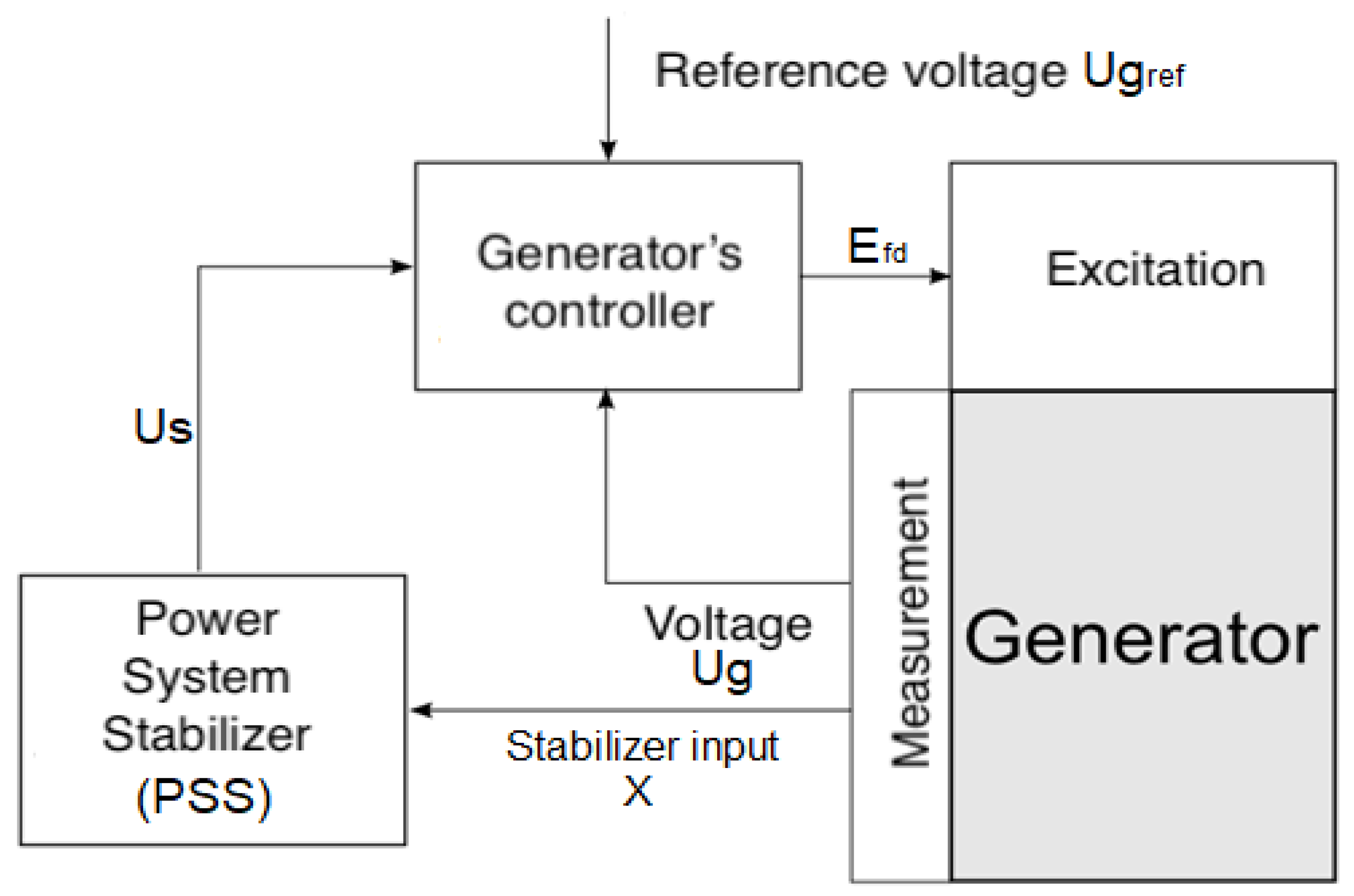
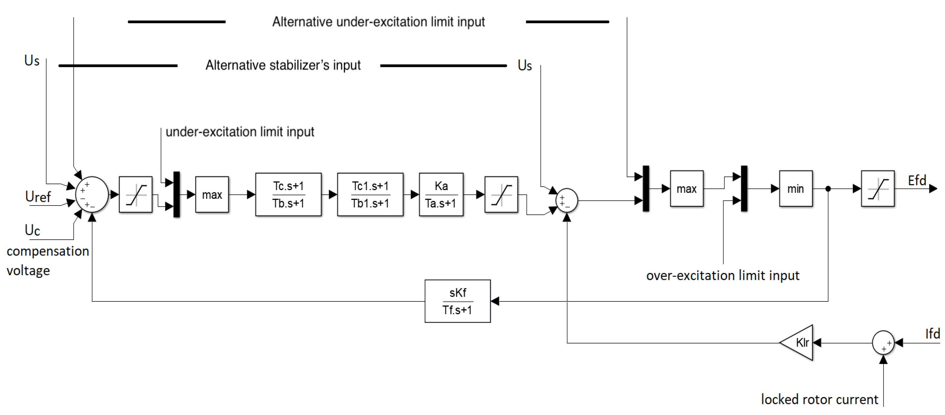
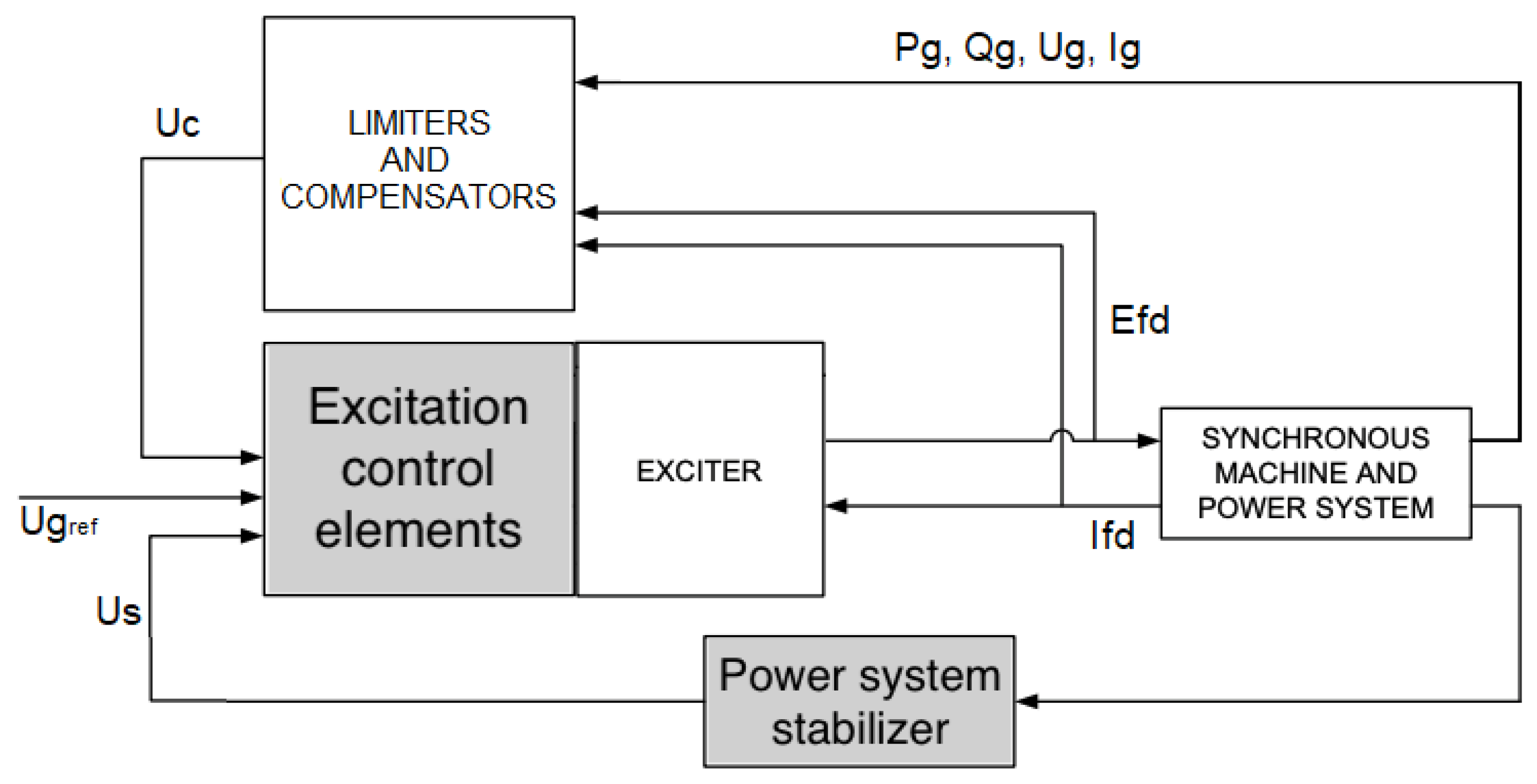
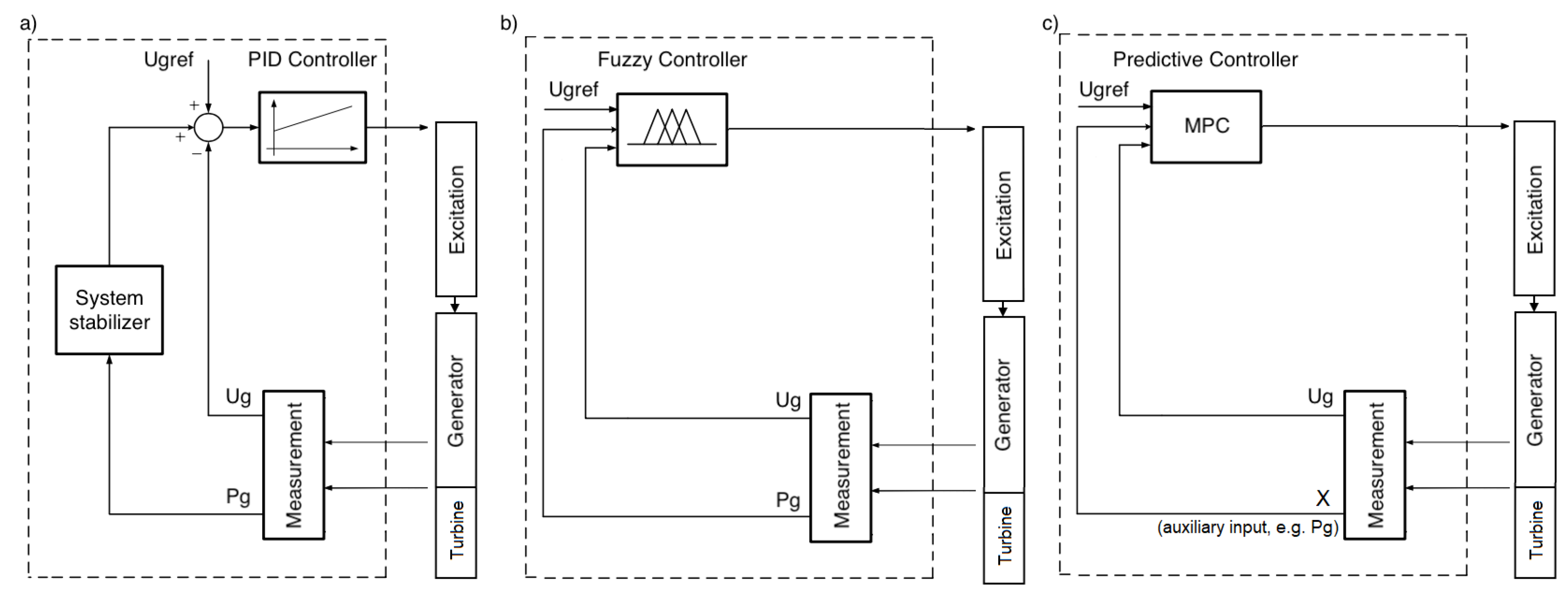
3.1. Classical Generator Control

The classical control system of the generator consists of an excitation controller, which changes the excitation voltage E f d that keeps the value of the voltage of the generator on a set value. There is also the power system stabilizer (PSS) in the considered control system which, on the basis of the information concerning the active power ( A g ), corrects the set point value (reference voltage U g , ref ) fed to the generator’s controller, in order to eliminate the oscillations in the active power delivered to the power system, as a result of the operation of the excitation controller (see Figure 1).
PSS is a part of an additional control loop. It adds a correction signal to the generator’s excitation controller using supplementary signal from the plant. As this auxiliary input signal for a power system stabilizer speed, voltage frequency or electrical power output can be used [14] (Figure 2).
The IEEE 421.5-2005 standard [14] describes numerous generator excitation controllers (e.g., the ST1A controller) and power system stabilizers [14] that form a simple PSS1A stabilizer to a complex double-input PSS7C. The control systems listed in IEEE 421.5-2005 consist of a number of lead-lag blocks; see Figure 2 and Figure 3.
Additionally, apart from the relationship between the excitation voltage E f d and the generator voltage U g , there is a relationship between the rotational speed in ω g and the voltage U g in the plant. This means that all rotational speed disturbances have an influence on the voltage value and must be compensated by an appropriate variation in the excitation voltage. Thanks to the additional information about the change in rotational speed, it is possible to better react to these changes. Due to the fact that the rotational speed is equal to the rotational speed of the turbine (common shaft) and, at the same time, also translates into the power transferred to the power system, it is possible to use a number of other substitute signals, i.e., active power of the generator, voltage frequency, or a change in the turbine power (e.g., opening angle of the control valve).
The classical generator control system consists of an excitation controller (PID-based), in which the task is to keep the generator voltage constant, and a system stabilizer, which, by correcting the set-point (the value to which the object is to be brought by the controller), minimizes power oscillations caused by the operation of the excitation controller.
In the paper, as a simple background for the analyzed MPC controllers, the classical generator control system was adopted. The standard [14] describes more complex structures, but they are all based on integral-derivative blocks with constraints; therefore, as a simple excitation controller, a PID controller was used, with an addition of a lead-lag module constituting a simple power system stabilizer.
The proposed new solution must cooperate with the existing structure and must both cooperate with the existing structure and ensure an equally high level of safety. Apart from the generator itself, the classical structure of generator control system (Figure 4) consists of the excitation and excitation control system, and the system stabilizer discussed in the article, as well as a whole series of limiters and protections. This structure is designed to maintain the generator voltage set point, while ensuring the plant’s operational safety and in such a way that it can replace classical solutions in accordance with the existing elements of the power system control. In order to be able to easily change the existing solutions to the proposed solutions, an identical structure of the control system with an excitation controller and an additional signal from the plant was adopted; see Figure 1. Thanks to this, the proposed solution uses exactly the same connections, and only the internal implementation differs from classical solutions using different control algorithms, see Figure 5.
The following subsections will describe the technologies used, i.e., recursive least squares method (RLS) and predictive control (MPC).

3.2. Recursive Least Squares Method

As the parameters of the object change during operation, it is necessary to modify the model to make it correspond to reality. For this purpose, the predictive control algorithm proposed in the paper was extended to include online model identification. Identification is a series of activities aimed at defining the mathematical description of the considered real plant (plant model). Unlike modeling, identification is based not on the laws of physics and known mathematical relationships but on experimental measurements of the quantities characterizing the inputs and outputs of an object [41]. On this basis, the interrelating relationships between them are determined, creating an object model. The identification result may be a non-parametric model (a model without parameters, e.g., in the form of a graph resulting from a spectral analysis) or a parametric model (defined by a set of parameters). The aim of parametric identification is to obtain a parametric model that describes the object dynamics well enough. The broad concept of identification covers many activities aimed at obtaining an unambiguous model, such as: designing the experiment, determining the model structure, selecting the identification method, estimating parameters, and verifying the model obtained [6]. A concept narrower than the concept of identification, and included in it, is the concept of estimation, which is a process aimed at obtaining model parameters similar to the real parameters of the object with the assumed accuracy. Obtaining parameters equal to the real parameters of a perfect model is possible only under specific conditions, the determination of which is necessary when designing the experiment and determining the structure of the model. In order to obtain compliant estimates (values of model parameters), i.e., corresponding to the actual parameters of the object, it is necessary that the structure of the model corresponds to the structure of the object, which is not always true (e.g., by reducing the model’s order to simplify the calculations). In such a case, the obtained estimation error will not converge to zero, regardless of the number of analyzed samples. Another important problem is the appropriate selection of the input signal at the design stage of the experiment. In order to obtain compatible parameters, assuming identical structures of the model and the object, it is necessary that the input signal is sufficiently exciting to enable precise determination of the object dynamics on the basis of the obtained samples. In order to estimate the parameters of complex objects, an appropriately complex input signal capable of obtaining sufficient information on the dynamics of objects is necessary. White noise–having non-zero values at all points of its spectrum–is an ideal input signal for parameter estimation. The problem that arises in this case is the implementation of complex signals and the limited possibility of using them on real objects, in situations where a given signal is not physically possible to implement, or if its implementation would lead to, e.g., dangerous situations. In the case of cooperation with the controller, the estimation takes place under the feedback conditions that affect the form of the input signal, which also limits the possibility of obtaining an arbitrary input signal.
It follows that the design of the experiment and the selection of the appropriate model structure are an important element of the identification process. When selecting the model class, it is necessary to pay attention to [6]:
1.
Flexibility, that is, extending the model in such a way that it is able to describe the largest possible family of objects, i.e., the model has a sufficient number of parameters to describe the complex dynamics of identified objects.
2.
Economy, the greatest possible simplification of the model and the number of parameters in order to avoid a situation in which several models with a given structure can describe the considered object, which leads to ambiguity, and also affects the extension of the calculation time.
3.
Algorithm complexity, which has a significant impact on the time of its implementation.
The next step, after selecting the model structure, is to define the methods of parameter estimation. There are many methods of parameter estimation, such as: least squares method, gradient method, instrumental variable methods, maximum likelihood method, and others [42]. Only the first method was used in this work, namely the Least Squares method, particularly its recursive version (Recursive Least Squares (RLS)).
It is necessary to clarify the distinction between estimation methods into recursive methods and batch methods. Batch methods are methods that use a ready-made dataset when all data is available in advance, before proceeding with parameter estimation. Recursive methods, on the other hand, consist of the continuous updating of the obtained result with new measurements flowing in on a regular basis. Because the topic of this work is the synthesis of a controller capable of adapting to changing conditions, it is necessary to apply methods that can update the values of model parameters on an ongoing basis in the event of their change. For this purpose, it is possible to use recursive online methods performed in real time, or cyclical estimation with batch methods. Initial, one-time estimation before starting the controller’s operation would not be able to take changes into account taking place in the facility. Due to the fact that the implementation of batch methods requires the storage of a significant amount of information about the previous values of the inputs and outputs of the object, a recursive method working online was selected for the implementation.
In general, for a typical ARX or ARMAX model [43] with a vector of unknown parameters θ ̲ R n , y t as the output signal sample, u t as the input, and ξ t as the disturbance sample, and on the basis of the so-called regression model
y t = φ ̲ t T θ ̲ + ξ t ,
the RLS algorithm is as follows:
θ ^ ̲ t = θ ^ ̲ t 1 + k ̲ t ε t ,
k ̲ t = P t φ ̲ t = P t 1 φ ̲ t 1 + φ ̲ t T P t 1 φ ̲ t ,
P t = P t 1 P t 1 φ ̲ t φ ̲ t T P t 1 λ + φ ̲ t T P t 1 φ ̲ t · 1 λ ,
ε t = y t φ ̲ t T θ ^ ̲ t 1 ,
with P t as a covariance matrix, k ̲ t as a gain vector, ε t as a prediction error, and, finally, 0 λ 1 as a forgetting factor. On the basis of a proper use of this algorithm, subject to additional potential requirements in the form of, e.g., exciting signal order, the estimates are obtained.
The proposed black-box model for the generator’s QDMC controller purposes, in the form of a discrete-time model, is presented with following structure [33]:
U g ( k ) = j = 1 n a ( j ) U g ( k 1 j ) + j = 1 n b ( j ) E f d ( k j ) + j = 1 n c ( j ) X ( k j ) ,
where a, b, c are generator’s model parameters which are obtained using the RLS method, and X is an additional, auxiliary, external input.
In the paper, four different external auxiliary inputs X are considered:
  • 0—no additional external auxiliary input is used,
  • ω —generator’s rotational speed,
  • P g —generator’s active power, and
  • α —turbine’s control valve opening degree (this signal can be exchanged between turbine’s and generator’s controllers without any additional measurements).
For further details on application of this model, please consult the next subsection. The full model of the generator can be found in Reference [36], whereas its discrete-time description can be found in Reference [33].
The last stage of the identification process is verification, which, in this case, consists of comparing the responses of the model and the object to the same input signal. On this basis, the estimation error is calculated, which is a measure of the accuracy of mapping the real object by the mathematical model. The model can be considered as representing the reality well if the obtained error is equal to zero or falls within the accepted error limits (if, for example, due to the structure not corresponding to the structure of the object, it is not possible to achieve zero error). The verification of the operation of the implemented RLS algorithm is presented in References [33,37,44], and a sample set of estimated parameters is presented in Figure 6.

3.3. Model Predictive Control

Typical generator control system was described in Section 3.1. In this paper, instead of typical integral-derivative blocks of the controller, the Quadratic Dynamic Matrix Control (QDMC) variant of an MPC controller for the purpose of control of a synchronous generator is suggested [45]. In order to obtain an improved quality in the closed loop system, i.e., the quality in a control loop binding the turbo-generator, one needs to introduce, to some extent, that exchange of information between the quadratic dynamic matrix controller and the environment form an additional signal, i.e., rotational speed ω , active power P g , or steam turbine’s control valve opening degree α . Furthermore, to cope with constantly changing operation point (the specific state of the facility in which it is located during operation) of the system, model adaptation using recursive least squares (RLS) algorithm is proposed.
Despite the fact that MPC control has become a standard method, it is not used in a larger scale in the power industry and in power plants control systems [46]. Changing the standard solution based on PID control allows one to take into account the knowledge of the plant during the control process and, thus, to efficiently optimize this process. One of the main advantages on the MPC-based solution is the possibility of taking all the plant-related constraints into account [47]. In addition, the operation of the MPC controller can be influenced by selecting appropriate parameters, i.e., control horizon, prediction horizon, or sampling period. Thanks to this, the behavior of the controller can be shaped in such a way as to best suit the requirements, e.g., quick control or smooth control without oscillations. As part of the research, the requirements for the excitation control system were analyzed, and the impact of changing the controller parameters on meeting these requirements was verified. The obtained results are presented in the article.
The diagram of the solution with the MPC controller and parameter estimation (RLS) is shown in Figure 7.
This solution will be compared to the solution with a simple PID controller, including a standard stabilizing unit in a power system (Figure 8), which is a simplification of a commonly used standard (implemented as an integral-derivative block). It is to be stressed that, despite the prior selection of a PID structure, the superior results have been obtained for no derivative action. In order not to narrow the scope of the discussion, the PID reference in the figures has been left. The proposed solution will be eventually compared with the solution in the form of a simple PID-driven system, including a standard stabilizing unit in a PSS; see Figure 8. For the system presented in this figure, the considered PID controller is fed with the generator’s voltage error and updated with the action exerted by a system stabilizer. There are many different structures of system stabilizers with different parameters [48]. Each of them can give different results and a different quality of control. Nevertheless, one of the simplified control systems was adopted so that it could constitute a comparative background for the proposed solutions.
The linear model of the process is used in a classical QDMC method taking its non-parametric model of a step response model in order to predict its future behavior [45,49]. The following equations can be easily traced back to the book of J. Maciejowski, as they are related to building a composite response to non-zero initial conditions and non-zero input on the basis of the superposition rule [47]. Taking a classical representation for the system with multiple (s) inputs and multiple (r)outputs, related to measured signals, one can introduce the following (7):
y ̲ k + 1 k = y ̲ k + 1 k 1 + A Δ u ̲ k + y ̲ k + 1 k d ,
where the sample number is denoted as k, the conditional information about the future sample is denoted as y ̲ k + 1 k and calculated on the basis of the information available at instant k, and y ̲ k + 1 k denotes a r p × 1 vector connected to the evolution of the future output available at sample t = k in p steps ahead (8):
y ̲ k + 1 k = [ ( y 1 ( k + 1 k ) , , y r ( k + 1 k ) ) , , ( y 1 ( k + p k ) , , y r ( k + p k ) ) ] T ;
next, y ̲ k + 1 k 1 denotes a r p × 1 vector connected to the unforced output sequence (with control signal held at its current prior value) (9):
y ̲ k + 1 k 1 = [ ( y 1 ( k + 1 k 1 ) , , y r ( k + 1 k 1 ) ) , , ( y 1 ( k + p k 1 ) , , y r ( k + p k 1 ) ) ] T ,
Δ u ̲ k denotes a s m × 1 is a sequence of control signal updates in m steps ahead (10):
Δ u ̲ k = [ ( Δ u 1 ( k ) , , Δ u s ( k ) ) , , ( Δ u 1 ( k + m 1 ) , , Δ u s ( k + m 1 ) ) ] T ,
and y ̲ k + 1 k d denotes a r p × 1 vector of the estimated disturbances, which simply boil down to the difference between the true signal values and the free response of the model, with A as a r p × s m dynamic matrix comprising step response samples of the multiple-input multiple-output system (11):
A = a ¯ 1 0 0 0 a ¯ 2 a ¯ 1 0 0 a ¯ p a ¯ p 1 a ¯ p 3 a ¯ p m + 1 ,
with every entry a ¯ i being a r × s matrix with r · s coefficients comprising step response information. Each matrix a ¯ l consists of all the step responses (12) [50]:
a ¯ l = a l 11 a l 12 a l 13 a l 1 s a l 21 a l 22 a l 23 a l 2 s a l r 1 a l r 2 a l r 3 a l r s ,
where a l r s are the coefficients of the step response in the sampling instant l, between input s and output r (which are usually calculated iteratively).
In order to calculate the optimal control signal update vector Δ u ̲ k , the solution to the QDMC problem is found at every step k [45,49]
min Δ u ̲ k J = [ y ̲ k ref y ̲ k + 1 k ] T Γ [ y ̲ k ref y ̲ k + 1 k ] + [ Δ u ̲ k ] T Λ [ Δ u ̲ k ] , s . t . y ̲ min y ̲ k 1 k y ̲ max , Δ u ̲ min Δ u ̲ k Δ u ̲ max , u ̲ min u ̲ k u ̲ max ,
with u ̲ k being a s m × 1 vector of control signals up to m steps ahead
u ̲ k = [ ( u 1 ( k ) , , u s ( k ) ) , , ( u 1 ( k + m 1 ) , , u s ( k + m 1 ) ) ] T ,
and a square diagonal Γ > 0 comprising weights of control signals, and Λ 0 defining penalizing coefficients for control signal updates. The notation from Table 1 is used for the described model.
The constrained QP problem in (13) is used to obtain the optimal control signal updates, with the first entries of the optimal control vector implemented to exert control over the plant. Subsequently, the solution procedure to the optimization problem is sought again, to abide a receding horizon methodology.
A proper choice of the sampling period is found according to the documentation of the GTHW-600 generator [38], with the dominating time constant estimated at T ^ = 0.0017 s (with generator’s time constants smaller in comparison to those of the turbine). As a result, sampling with T = 0.00001 s satisfies the engineering rule to have at list 10 sample hits per the major time constant, to possibly minimize the possibility to give rise to errors in simulating dynamical models. By doing so, one avoids typical problem related to averaging feature of the predictive controller. In order to abide by this rule, the prediction horizon will be in the range of 10 ÷ 20 (tuning of the prediction horizon will be discussed later on), which relates to times in the span of 0.0001 ÷ 0.0002 s .
The structure of functionality of synchronous generator’s QDMC is presented in Figure 9. The optimized controllers need only the time response model, estimated on the basis of a black-box model, in a real time, whenever operating points of the set of a turbo-generator change. For this purpose, the recursive least-squares method is adopted [51], on the basis of the data originating from the measurements.
The structure of the model used during the identification was selected on the basis of a complex, non-linear model of the power plant’s turbine-generator set. Based on the analysis of the plant, the 7th order of the model was adopted [33], which should reflect the object dynamics. Using the RLS method, the parameters of the (6) discrete input-output model were identified.
Unfortunately, the QDMC algorithm uses a non-parametric object model in the form of a step response characteristic; thus, the actually identified model () data had to be used for recalculation purposes at each control step based on the said discrete model (Figure 9).
The whole procedure of calculating the step response model for the proposed QDMC controller can be described as follows:
1.
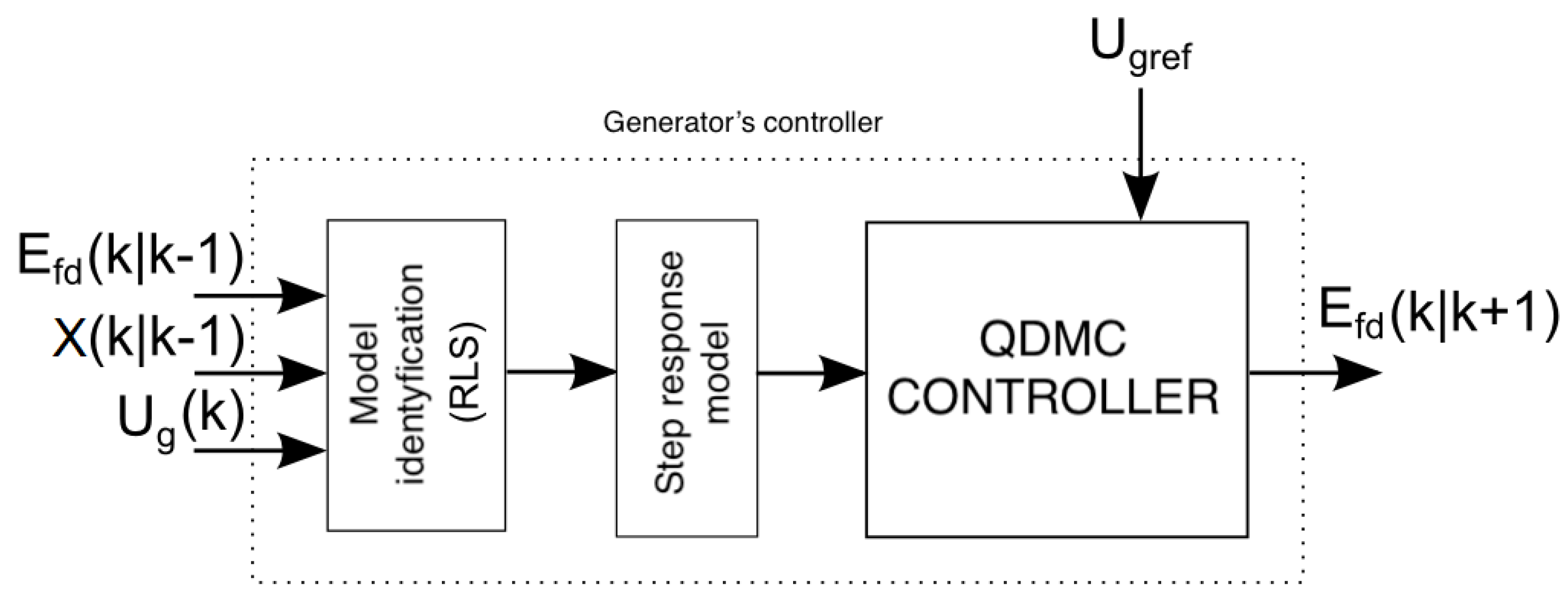
Determining the structure of the discrete input-output model (6).
2.
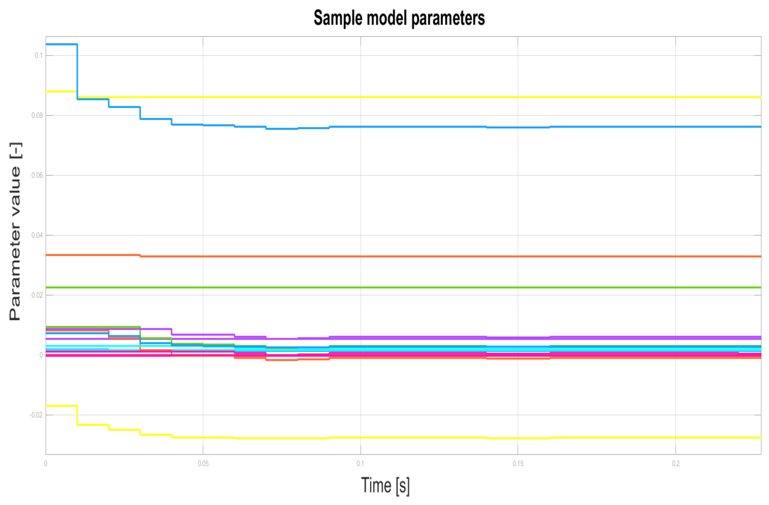
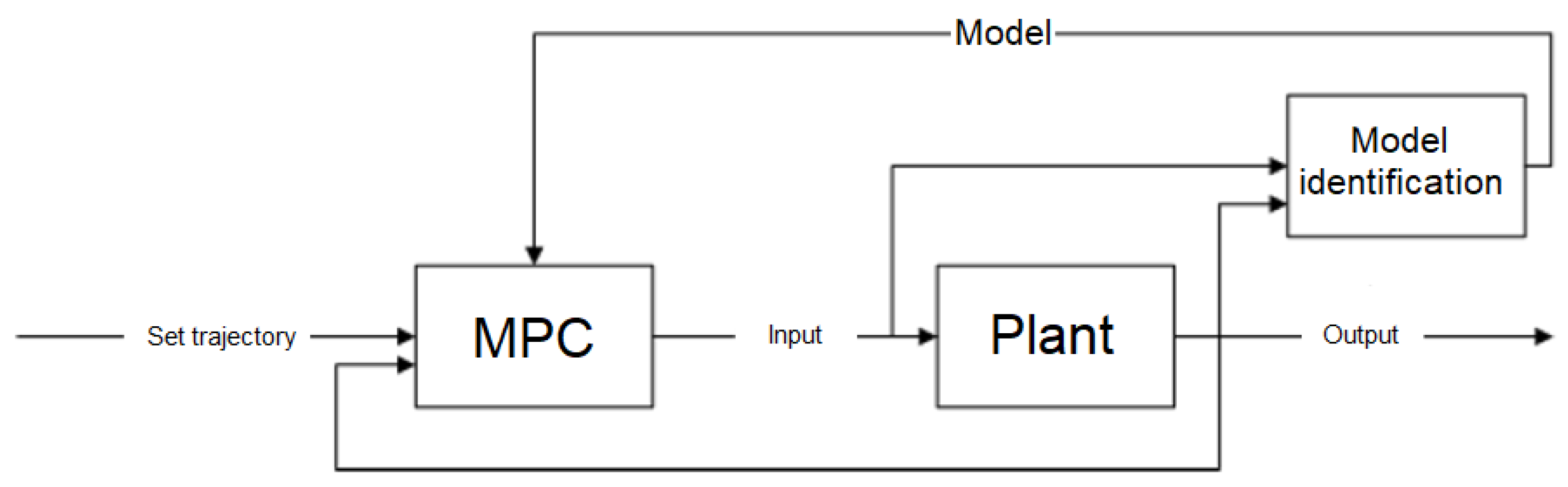
Identification of model parameters at each step of the algorithm operation (RLS, Section 3.2).
3.
Calculation of the step response model based on the current discrete model at each step of the algorithm operation.
4.
The use of the step response model in the algorithm of the MPC controller.
The number n of consecutive black-box model samples (Equation (6)) has been selected ad hoc to be n = 7 with relation to the order the model of the turbine-generator set in the most complex model path ( α U g ). The order has been chosen to mirror the trade-off between the simplicity of the model, building the overparametrized model. The selected order is a result of summing up the orders of all the elements of the system, i.e., a steam turbine (2) [40] and the order of the synchronous generator (5) [52]. As per the use of the auxiliary signal in the considered model, the final order of the model has been selected to be equal to 7, to capture all the properties of the system.
On the other hand, the QDMC algorithm is based on solving the quadratic programming problem (QP), which, using modern numerical methods and fast computers, can be solved online during the operation of the turbo-generator set.
As for the QP problems considered, let us present one of the effective strategies to tackle the problem out, namely the active set method. For the optimization problem with a quadratic term
min x ¯ ̲ x ̲ T A x ̲ + b ̲ T x ̲ + c     s . t . a ̲ bound , i T x ̲ = b bound , i ( i = 1 , 2 , , p ) , a ̲ bound , i T x ̲ b bound , i ( i = p + 1 , p + 2 , , m ) ,
an improved solution is sought:
x ̲ ( k + 1 ) = x ̲ ( k ) + α d ̲ x ( k ) .
Some inequality constraints in the current solution x ̲ ( k ) might be active and form the so-called active set, related to the indices
W ( k ) = 1 , 2 , , p i : a ̲ bound , i T x ̲ ( k ) = b bound , i , i = p + 1 , p + 2 , , m .
The descent direction can be identified from
min d ̲ ( k ) x ̲ ( k ) + d ̲ x ( k ) T A x ̲ ( k ) + d ̲ x ( k ) + b ̲ T x ̲ ( k ) + d ̲ x ( k ) + c     s . t . a ̲ bound , i T x ̲ ( k ) + d ̲ x ( k ) = b bound , i ( i W ( k ) )
or from
min d ̲ ( k ) d ̲ x ( k ) T A d ̲ x ( k ) + 2 A x ̲ ( k ) + b ̲ T d ̲ x ( k )     s . t . a ̲ bound , i T d ̲ x ( k ) = b bound , i a ̲ bound , i T x ̲ ( k ) = 0 ( i W ( k ) ) .
Having introduced the following:
g ̲ ( k ) = 2 A x ̲ ( k ) + b ̲ , A bound = [ a ̲ bound , 1 T , a ̲ bound , 2 T , ] T , i W ( k ) ,
the final optimization problem is obtained
min d ̲ ( k ) d ̲ x ( k ) T A d ̲ x ( k ) + g ̲ ( k ) T d ̲ x ( k )     s . t . A bound d ̲ x ( k ) = 0 ̲ .
On the basis of the KKT conditions for such a problem, the sought direction of improvement satisfies
2 A A bound T A bound 0 d ̲ x ( k ) λ ̲ = g ̲ ( k ) 0 ̲ .
As per a ̲ bound , i T d ̲ x ( k ) < 0 violating no constraints, the step length is obtained from
α a ̲ bound , i T d ̲ x ( k ) b bound , i a ̲ bound , i T x ̲ ( k ) , i W ( k ) , α = min a ̲ bound , i T d ̲ x ( k ) > 0 i W ( k ) 1 , b bound , i a ̲ bound , i T x ̲ ( k ) a ̲ bound , i T d ̲ x ( k ) .
On the basis of the values of the Lagrange multipliers, inactive constraints are eliminated, and the rest of them form the so-called active set. Summing up, the steps are as follows:
(1)
obtain g ̲ ( k ) = 2 A x ̲ ( k ) + b ̲ ;
(2)
solve
2 A A bound T A bound 0 d ̲ x ( k ) λ ̲ = g ̲ ( k ) 0 ̲ ;
(3)
if d ̲ ( k ) = 0 ̲ , proceed to the last step; otherwise, proceed to the next step;
(4)
calculate the step length
α = min a ̲ bound , i T d ̲ x ( k ) > 0 i W ( k ) 1 , b bound , i a ̲ bound , i T x ̲ ( k ) a ̲ bound , i T d ̲ x ( k ) ,
and add the active constraint to the active set whenever α < 1 ;
(5)
improve the solution
x ̲ ( k + 1 ) = x ̲ ( k ) + α d ̲ x ( k ) ,
and substitute k : = k + 1 and proceed to Step 1; and
(6)
check the sign of the Lagrange multipliers for inequality constraints: stop the algorithm if no multiplier is nonnegative; otherwise, remove the constraint corresponding to the largest positive multiplier and proceed to Step 2.
Currently, research is carried out to implement real-time predictive control algorithms with the use of microcontrollers or programmable FPGA gate arrays (References [53,54,55]). The results obtained so far allow us to state that the proposed solution is feasible, as well as that the distributed DMPC control system of the nuclear power plant turbine set is possible to implement and work in real time.

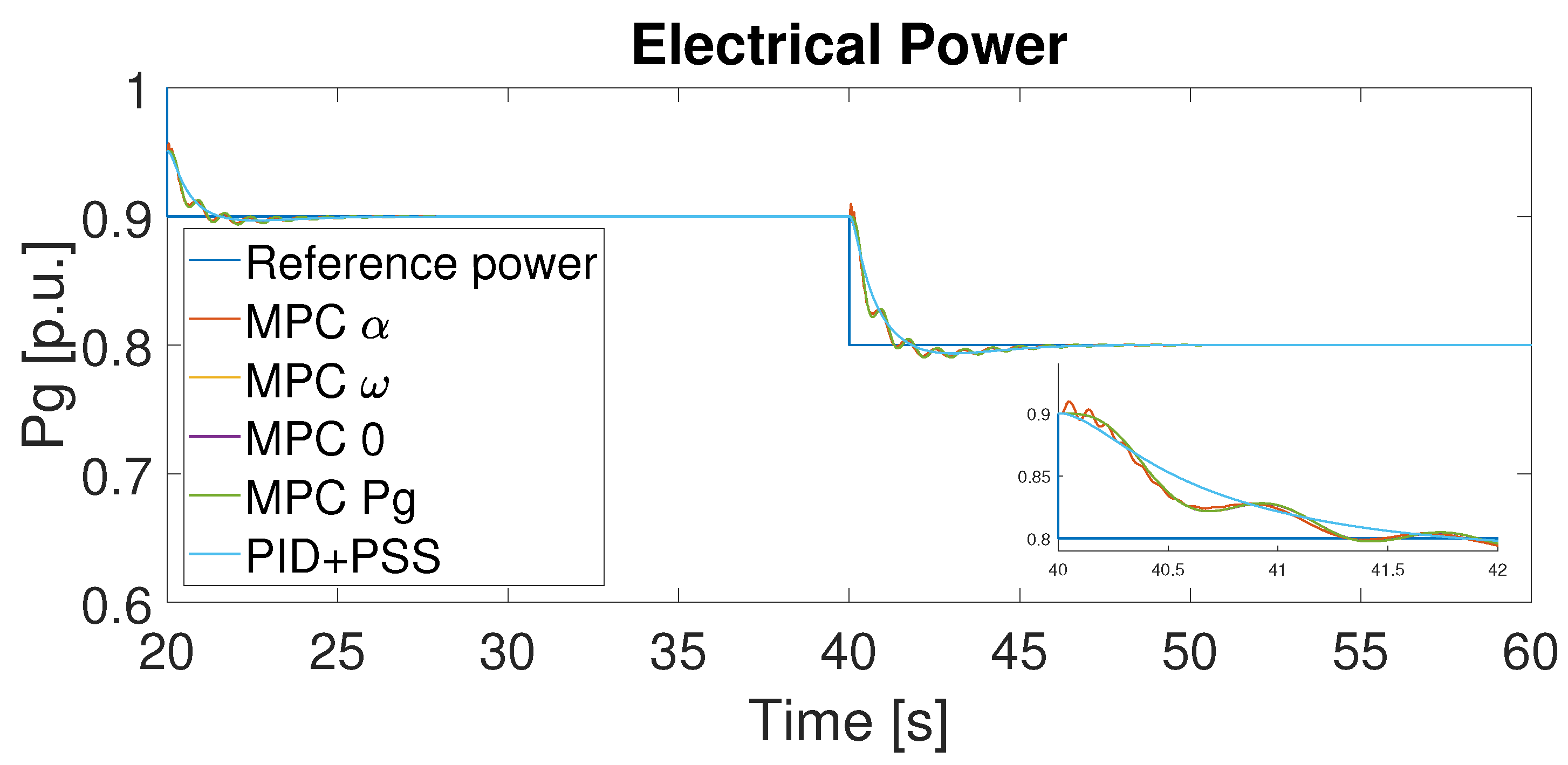
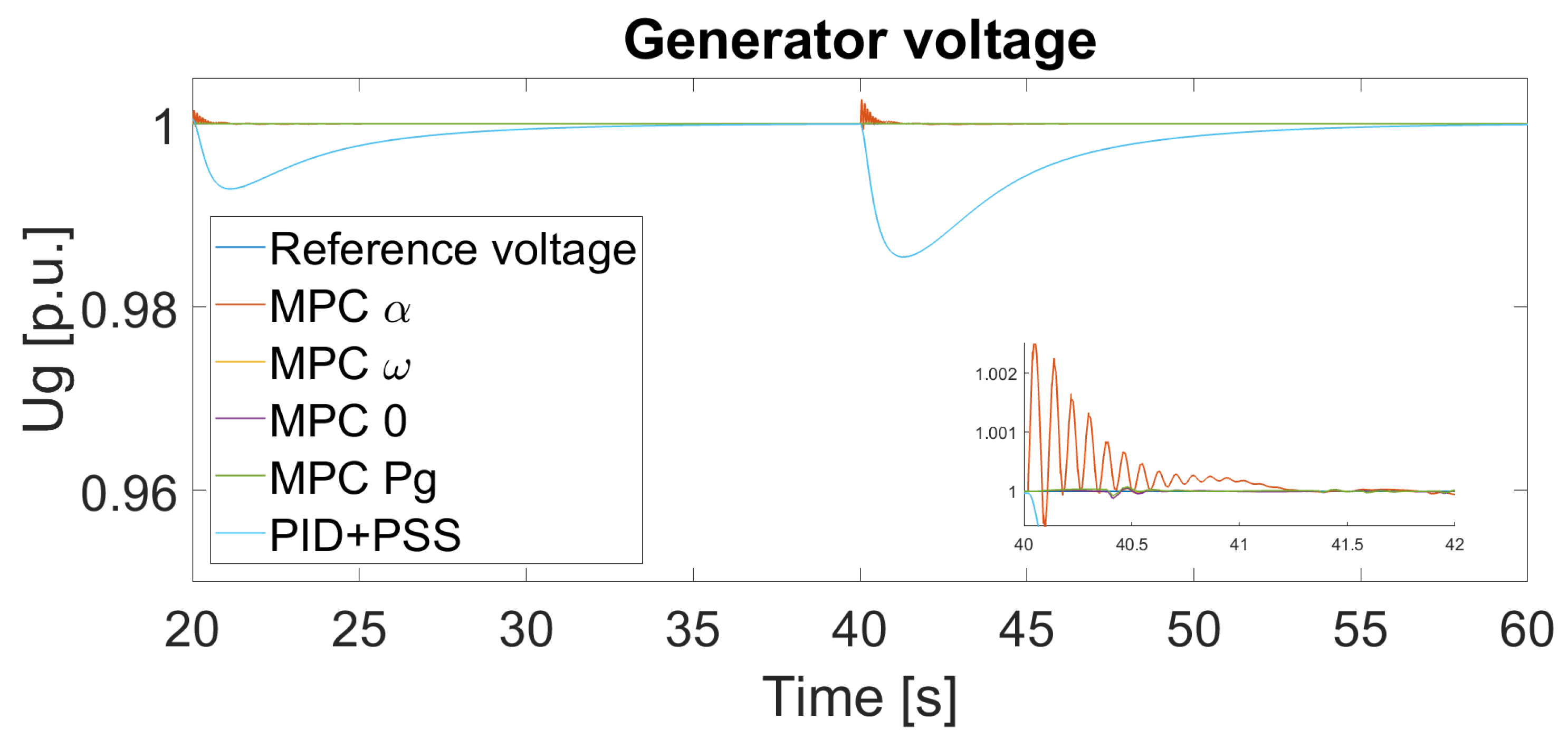
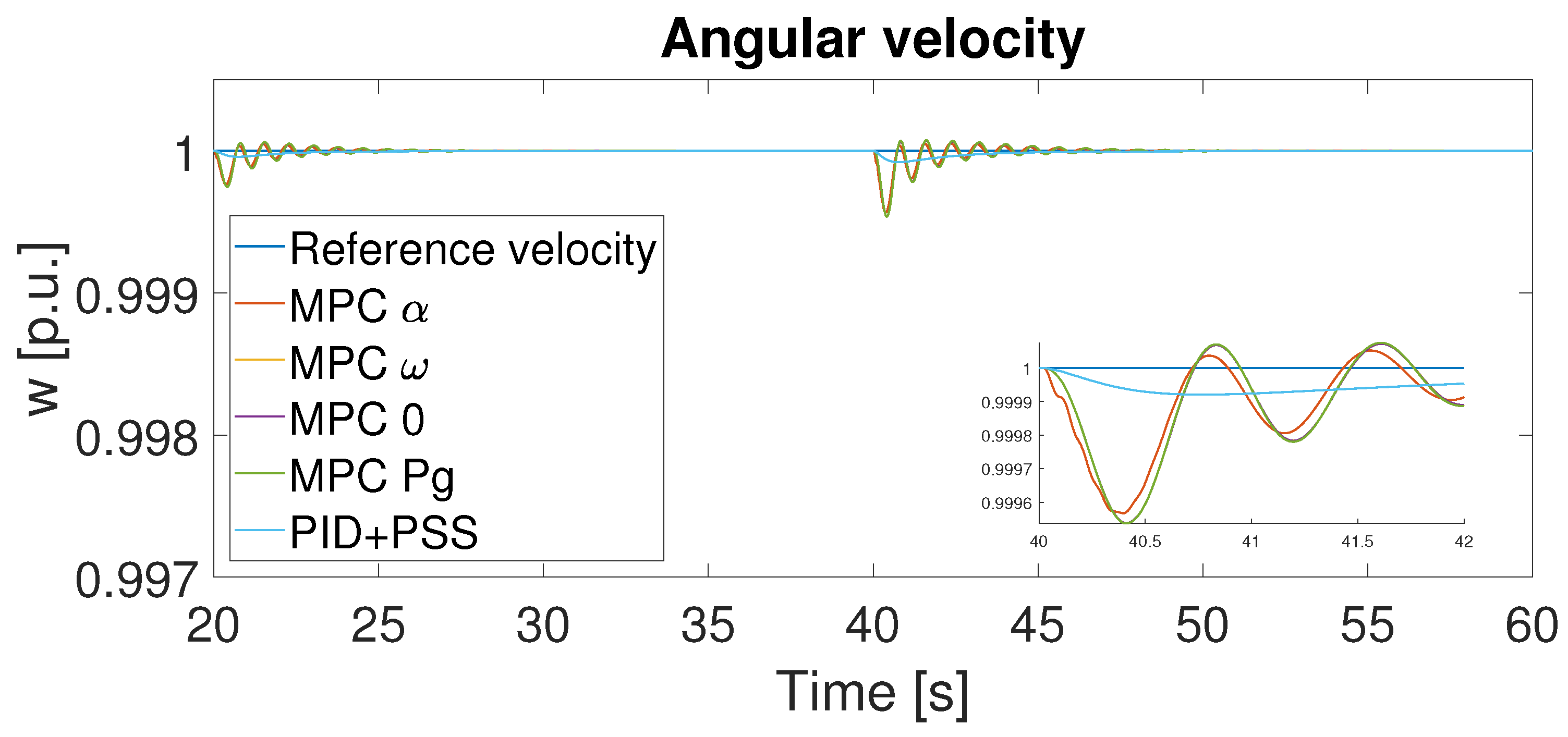
4. Simulation Test Results

During the simulation test studies, the developed synchronous generator’s control algorithms were verified. The analysis of the QDMC control system, which was considered in the course of the research, was performed using a predictive controller instead of the classical (according to the IEEE standard) controller of the generator. MPC controllers with a different additional signal each were compared with a simplified PID + PSS solution.
Five different cases were identified to be of interest:
  • MPC α —an MPC controller with turbine’s control valve opening α as an external auxiliary input,
  • MPC ω —an MPC controller with rotational speed ω as an external auxiliary input,
  • MPC P g —an MPC controller with active power P g as an external auxiliary input,
  • MPC 0 —an MPC controller without any external auxiliary input, and
  • PID + PSS —a simple controller based on PID and a simple system stabilizer.
As previously stated, each of the aforementioned signals allows for taking into account indirectly changes in rotational speed in the generator voltage control algorithm. These signals differ in the availability of measurements and in dynamics. The change of the control valve opening set-point is a signal from another controller, so it is available without additional measurements, while the speed and power are available by measurement. On the other hand, these measurements allow for determination of the actual change in speed causing disturbances in the voltage waveform. The set point for valve opening causes the speed to change; so, it is a signal with completely different dynamics. However, it is assumed that, due to the fact that the MPC controller has a model of the plant, it is able to take into account the dynamics of the turbine and correctly use this information. Such a set of signals was selected in order to verify the solution with the use of classical signals (rotational speed, power) and, at the same time, to verify the possibility of using a signal coming not from the measurement but from another control system for the purposes of cooperative control (valve opening set-point) [33]. As the background, for the comparison purposes, systems without an additional auxiliary signal and the classical PID + PSS solution are used (Figure 8).
Parameters of particular controllers have been altered and applied for the simulation purposes to the system to examine its performance. In Simulink, and in order to estimate the value of the cost function, a gradient-based solver has been used. The integral of squared error (ISE) and the integral of squared error multiplied by time (ITSE) were used as objective functions, defined as follows:
f ISE = t 0 t f x ( P g , ref P g ) 2 + y ( U g , ref U g ) 2 + z ( ω g , ref ω g ) 2 d t ,
f ITSE = t 0 t f u ( P g , ref P g ) 2 t + v ( U g , ref U g ) 2 t + w ( ω g , ref ω g ) 2 t d t ,
where:
P g , P g , ref —active power and active power set point.
U g , U g , ref —RMS voltage and RMS voltage set point.
ω g , ω g , ref —angular speed and angular speed set point.
x , y , z , u , v , w —weights (for P g , U g , ω g , for ISE and ITSE, respectively).
t—simulation time.
t 0 , t f define the time span to calculate ISE/ITSE performance indices.
The ISE performance index allows for determination of the size of the error in time (integral), as well as finding a solution that minimizes the total error and comparing the solutions due to the total control error that occurs during their operation. The ITSE criterion, additionally, allows for assessment of the accuracy of stabilization, taking into account the stabilization time, increasing the error weight with time. In contrast to the ISE criterion, which is the integral of the square of the error, it allows for taking into account not only the amplitude of the disturbances but the rate of their suppression; time is also used as a weight.
The selection method of controllers’ parameters is briefly presented in Figure 10. In order to obtain the optimal values for the gains of the controller, namely K p , K i , K d , T i , T d , and T 1 , T 2 for a simple power system stabilizer, the gradient algorithm has been run over a 100 of iterations with a random initial guess [35]. In the case of the MPC controller, the control horizon was set to s = 1 sample as the plant is non-linear, and the model is changing online with the simulation. The aim of reducing the control horizon is to reduce the error caused by the uncertainty of the model. The prediction horizon was changed during the simulation in range 10 p T 23 . The horizon greater than 10 was chosen due to the loss of stability at lower values. From this value, the horizon was increased by analyzing the change in quality indices, up to the value of 23, at which the quality indices started to decrease.
Table 2 shows the ISE calculated for different prediction horizons p G (the control horizon in all cases was equal s G = 1 ), together with different values of the turbine’s MPC control horizon p T (wit the control horizon s T = 1 ). To find the minimum of the ISE, taking into account the behavior of the turbine (connected with the generator by a common shaft) and the generator, an extensive search, including 112 simulations, was performed (without any additional tuning optimizations procedures [56]).
Additionally, one more experiment was performed to check if, for the different types of the auxiliary input, different values of the prediction horizon should be chosen (Table 3 and Table 4). Based on this results, it was decided to use the same prediction horizon for all the cases, as the differences are negligible.
The parameters resulting from the aforementioned experiments are collected in the Table 5.
During the experiments, it was established that the changing prediction horizon for different MPC controllers (with a different additional input) does not influence the performance; thus, for all further experiments, the same set of parameters was used.
The change of the power set by the power disposition was chosen as the test case. It is a case of normal operation of a power plant block, in which the control systems stabilize the voltage and frequency of the voltage ( U g , ω g ) in order to maintain its quality, and the power ( P g ) demand changes due to the connection/disconnection of loads.
The test experiment consisted in a step change of the active power set point value by 10% every 20 s of the simulation. There are restrictions on control signals α [ 0 , 100 ] , E f d [ 0.1 , 0.1 ] . Figure 11, Figure 12, Figure 13 and Figure 14 and Table 6 present the results of the simulation tests. A detailed description of the experiment can be found in Reference [37]. According in Reference [57], p. 23, Table 4, which defines parameters for active power frequency response, the admissible dead-zone secures the case of neglectful oscillations visible in the figures. Besides, the amplitude of oscillations virtually vanishes for the un-zoomed case of the plot.
The developed predictive controller ensures superior maintaining the set trajectory of the generator voltage in comparison to the PID + PSS controller and also takes into account the limitations existing in the model. The MPC regulator stabilizes the voltage value better, but—due to the relationship between the voltage value and the rotational speed of the generator—it causes larger oscillations of the rotational speed (voltage frequency). PID + PSS is, therefore, better at damping oscillations but at the cost of voltage stabilization. Among the considered MPC regulators, the lowest ISE/ITSE value was achieved for the solution using the turbine’s control valve opening as an auxiliary input α . This signal is the only one available without measurement and can be sent directly from the turbine regulator to the generator regulator. Although the use of the MPC controller increases the oscillation in relation to the classic controller, the use of an additional input allows for reduction of this effect. The obtained results (influence of the auxiliary input, influence of the use of the turbine’s control valve opening signal) will be used in the continuation of research on cooperative DMPC control [33], in which individual control systems exchange information about the calculated control signals.
The conducted tests, the results of which are presented in the paper, also prove the validity of using the QDMC controller in place of the typically used controllers based on integral-derivative blocks with system stabilizer, with no visible increase in the computational burden, as a single decision at a single sampling instant takes milliseconds (and can be reduced using an analytic solution to the MPC problem instead of solving a quadratic programming problem in every step), and fully enables one to use it in the real time, as it is the order of the magnitude of the smallest time constant of the generator.

5. Conclusions

By extending the model used in the MPC control, it is possible to include an additional signal extending the controller’s knowledge of the plant. Due to the existing relationship between the voltage and the rotational speed of the generator, adding α , ω , P g signals allows for taking this relationship into account when calculating the control signal. In this way, it is possible to take into account the function of the system stabilizer, i.e., minimizes the oscillations of the active power delivered to the power system caused by the operation of the excitation controller. The results of the simulation tests confirm the influence of the additional control signal on the occurrence of power and voltage oscillations, and the use of various additional signals allows for achievement of different dynamics of the controller. Especially useful and promising is the turbine’s control valve opening α . Due to the fact that the control valve opening signal is calculated by the turbine controller and is directly available from the computer system level (without additional measurements or estimation), it was used in Reference [33] as an additional signal when exchanging information between the two QDMC controllers of the turbine and the generator (DMPC distributed model predictive controller of a turbine-generator set).
As standard PID-based control systems are used, these can be extended with an additional element in the form of a system stabilizer used to minimize the oscillations appearing in the power system. In order to improve the efficiency of this systems, more complex ones, consisting of a greater number of I or D blocks, or built with a greater number of parallel paths, are proposed. The literature suggests, e.g., solutions based on fuzzy logic [15,16,17,18,19,20,21]. The authors propose a different approach in the form of the MPC controller, taking the operation of the system stabilizer, thanks to an additional input signal, into account. This solution complements the research on the distributed control of the turbine-generator unit [33]. The presented considerations constitute the basis of the distributed predictive control scheme proposed in earlier research with the auxiliary signal exchanged between the control systems. The aforementioned turbine-generator set’s control system will be a prelude to further research.

Author Contributions

Conceptualization, P.S., B.C. and D.H.; methodology, P.S.; software, P.S.; validation, P.S., B.C., T.A.R., D.Z. and D.H.; formal analysis, D.H., P.S.; investigation, B.C., P.S.; resources, P.S., B.C.; writing—original draft preparation, P.S., B.C., D.H.; writing—review and editing, B.C., D.H., T.A.R., D.Z.; visualization, P.S.; supervision, D.H., B.C.; funding acquisition, D.H. All authors have read and agreed to the published version of the manuscript.

Funding

This research was funded in part by the Poznan University of Technology under Grant 214/SBAD/0229.

Institutional Review Board Statement

Not applicable.

Informed Consent Statement

Not applicable.

Data Availability Statement

The study did not report any data.

Conflicts of Interest

The authors declare no conflict of interest.

References

  1. Polish Power Networks (In Polish: Polskie Sieci Elektroenergetyczne S.A.). Annual Reports. Available online: https://www.pse.pl/dane-systemowe/funkcjonowanie-kse/raporty-roczne-z-funkcjonowania-kse-za-rok/raporty-za-rok-2020 (accessed on 13 June 2021).
  2. Energy Policy of Poland until 2040 Appendix 2 Conclusions from Forecast Analyses for the Energy Sector. Available online: https://www.gov.pl/web/klimat/polityka-energetyczna-polski (accessed on 20 June 2021).
  3. National Energy and Climate Plans, Assessment of the Final National Energy and Climate Plan of Poland. Available online: https://ec.europa.eu/energy/sites/default/files/documents/staff_working_document_assessment_necp_poland_en.pdf (accessed on 25 June 2021).
  4. Commission Implementing Decision (EU) 2017/ 1442-of 31 July 2017-Establishing Best Available Techniques (BAT) Conclusions, under Directive 2010/ 75/ EU of the European Parliament and of the Council, for Large Combustion Plants- (Notified Under Document C (2017) 5225). Available online: https://eur-lex.europa.eu/legal-content/EN/TXT/PDF/?uri=CELEX:32017D1442&from=EN (accessed on 25 June 2021).
  5. Forecast of Peak Demand for Power in 2016–2035. Available online: https://www.pse.pl/-/prognoza-pokrycia-zapotrzebowania-szczytowego-na-moc-w-latach-2016-2035 (accessed on 27 June 2021). (In Polish).
  6. Polish Power Networks (In Polish: Polskie Sieci Elektroenergetyczne S.A.). Daily Reports. Available online: https://www.pse.pl/dane-systemowe/funkcjonowanie-kse/raporty-dobowe-z-pracy-kse (accessed on 28 June 2021).
  7. The Polish Nuclear Power Programme 2020. Available online: https://www.gov.pl/web/polski-atom/program-polskiej-energetyki-jadrowej (accessed on 27 June 2021).
  8. Oettingen, M. Assessment of the Radiotoxicity of Spent Nuclear Fuel from a Fleet of PWR Reactors. Energies 2021, 14, 3094. [Google Scholar] [CrossRef]
  9. Koltun, P.; Tsykalo, A.; Novozhilov, V. Life Cycle Assessment of the New Generation GT-MHR Nuclear Power Plant. Energies 2018, 11, 3452. [Google Scholar] [CrossRef] [Green Version]
  10. Sroka, K.; Grządzielski, I. Nuclear power plants in conditions of a catastrophic failure of power system (in Polish) Elektrownie jądrowe w warunkach awarii katastrofalnej. Acta Energy 2011, 1, 5–10. [Google Scholar]
  11. Hovsapian, R.; Osorio, J.D.; Panwar, M.; Chryssostomidis, C.; Ordonez, J.C. Grid-Scale Ternary-Pumped Thermal Electricity Storage for Flexible Operation of Nuclear Power Generation under High Penetration of Renewable Energy Sources. Energies 2021, 14, 3858. [Google Scholar] [CrossRef]
  12. Vajpayee, V.; Top, E.; Becerra, V.M. Analysis of Transient Interactions between a PWR Nuclear Power Plant and a Faulted Electricity Grid. Energies 2021, 14, 1573. [Google Scholar] [CrossRef]
  13. Peakman, A.; Merk, B.; Hesketh, K. The Potential of Pressurised Water Reactors to Provide Flexible Response in Future Electricity. Energies 2020, 13, 941. [Google Scholar] [CrossRef] [Green Version]
  14. Power, I.; Society, E. IEEE Recommended Practice for Excitation System Models for Power System Stability Studies; IEEE Std 421.5-2016; IEEE: Piscataway, NJ, USA, 2016. [Google Scholar]
  15. Tianshuo, S.; Ying, L.; Bin, H.; Dan, L.; Xiaoming, L. Simulation Study on Fuzzy Controller for Main Circuit of the Excitation Control System. In Proceedings of the 2013 IEEE International Conference on Vehicular Electronics and Safety, Dongguan, China, 28–30 July 2013. [Google Scholar]
  16. Ramya, R.; Selvi, K. A Simple Fuzzy Excitation Control System for Synchronous Generator. In Proceedings of the 2011 International Conference on Emerging Trends in Electrical and Computer Technology, Nagercoil, India, 23–24 March 2011. [Google Scholar]
  17. Gunes, M.; Dogru, N. Fuzzy Control of Brushless Excitation System for Steam Turbogenerators. IEEE Trans. Energy Convers. 2010, 25, 844–852. [Google Scholar] [CrossRef]
  18. Kitauchi, Y.; Taniguchi, H. Experimental Verification of Fuzzy Excitation Control System for Multi-machine Power System. IEEE Trans. Energy Convers. 1997, 12, 94–99. [Google Scholar] [CrossRef]
  19. Hiyama, T.; Miyazaki, K.; Satoh, H. A Fuzzy Logic Excitation System for Stability Enhancement of Power Systems with Multi-mode Oscillations. IEEE Trans. Energy Convers. 1996, 11, 449–454. [Google Scholar] [CrossRef]
  20. Cheng, Y.; Jiang, Z.; Xu, D.; Liu, Y. Nonlinear Analytical Fuzzy Logic Control of Generator Excitation. In Proceedings of the 2008 Third International Conference on Electric Utility Deregulation and Restructuring and Power Technologies, Nanjing, China, 6–9 April 2008. [Google Scholar]
  21. Al-Turki, Y.A.; Attia, A.F.; Soliman, H.F. Optimization of Fuzzy Logic Controller for Supervisory Power System Stabilizers. Acta Polytech. 2012, 52, 7–16. [Google Scholar] [CrossRef]
  22. Kim, K.; Rao, P.; Burnworth, J. Application of Swarm Intelligence to a Digital Excitation Control System. In Proceedings of the 2008 IEEE Swarm Intelligence Symposium, St. Louis, MO, USA, 21–23 September 2008. [Google Scholar]
  23. Hema’ndez, J.A.; Botero, H.A.; Ospina, J.D.; Perez, J.C. Excitation System Parameters Estimation Using Evolutionary Algorithms. In Proceedings of the 2006 IEEE/PES Transmission & Distribution Conference and Exposition: Latin America, Caracas, Venezuela, 15–18 August 2006. [Google Scholar]
  24. Gong, R.; Huang, Y.; Wei, H.; Meng, X.; Xie, L. Design of PID Excitation Controllers for Synchronous Generators Based on Fuzzy RBF Neural Network. In Proceedings of the 2008 International Conference on Electrical Machines and Systems, Wuhan, China, 8 August 2008. [Google Scholar]
  25. He, H.; Zhou, J.; Lei, H.; Li, C.; Yang, L. Research on fuzzy-PID excitation controller of synchronous generator based on improved PSO algorithm. In Proceedings of the Eighth International Conference on Machine Learning and Cybernetics, Baoding, China, 12–15 July 2009. [Google Scholar]
  26. Sun, L.; Feng, J.; Dimirovski, G.M.; Zhao, J. Adaptive Robust H∞ Control of the Generator Excitation System. In Proceedings of the 2009 American Control Conference, St. Louis, MO, USA, 10–12 June 2009. [Google Scholar]
  27. Suminal, D.; Erceg, G.; Idzotic, T. Excitation control of a synchronous generator using fuzzy logic stabilizing controller. In Proceedings of the 2005 European Conference on Power Electronics and Applications, Dresden, Germany, 11–14 September 2005. [Google Scholar]
  28. Park, Y.M.; Choi, M.S.; Lee, K. A neural network-based power system stabilizer using power flow characteristics. IEEE Trans. Energy Convers. 1996, 11, 435–441. [Google Scholar] [CrossRef]
  29. Keskes, S.; Bouchiba, N.; Sallem, S.; Chrifi-Alaoui, L.; Kammoun, M.B.A. Optimal tuning of power system stabilizer using genetic algorithm to improve power system stability. In Proceedings of the 2017 International Conference on Green Energy Conversion Systems (GECS), Hammamet, Tunisia, 23–25 March 2017; pp. 1–5. [Google Scholar] [CrossRef]
  30. Boyd, S.; Vandenberghe, L. Convex Optimization; Cambridge University Press: Cambridge, UK, 2004. [Google Scholar] [CrossRef]
  31. Löfberg, J. YALMIP: A Toolbox for Modeling and Optimization in MATLAB. In Proceedings of the 2004 IEEE International Conference on Robotics and Automation, Taipei, Taiwan, 2–4 September 2004. [Google Scholar]
  32. Heemels, W.P.M.H.; Donkers, M.C.F.; Teel, A.R. Periodic Event-Triggered Control for Linear Systems. IEEE Trans. Autom. Control 2013, 58, 847–861. [Google Scholar] [CrossRef]
  33. Sokólski, P.; Rutkowski, T.; Duzinkiewicz, K. The distributed model predictive controller for the nuclear power plant turbo-generator set. Adv. Intell. Syst. Comput. 2017, 577, 682–687. [Google Scholar]
  34. Sokolski, P.; Rutkowski, T.; Duzinkiewicz, K. Simplified, multiregional fuzzy model of a nuclear power plant steam turbine. In Proceedings of the 21ST International Conference on Methods and Models in Automation and Robotics (MMAR), Miedzyzdroje, Poland, 29 August–1 September 2016; pp. 379–384. [Google Scholar]
  35. Sokólski, P.; Kobylarz, A.; Kulkowski, K.; Duzinkiewicz, K.; Rutkowski, T.; Grochowski, M. Advanced control structures of turbo generator system of nuclear power plant. Acta Energy 2015, 3, 83–96. [Google Scholar] [CrossRef] [Green Version]
  36. Sokolski, P.; Rutkowski, T.; Duzinkiewicz, K. The excitation controller with gain scheduling mechanism for synchronous generator control. In Proceedings of the 2015 20TH International Conference on Methods and Models in Automation and Robotics (MMAR), Miedzyzdroje, Poland, 24–27 August 2015; pp. 23–28. [Google Scholar]
  37. Sokólski, P.; Rutkowski, T.; Duzinkiewicz, K. The QDMC Model Predictive Controller for the Nuclear Power Plant Steam Turbine Control. In Krajowa Konferencja Automatyki; Advances in Intelligent Systems and Computing Book Series (AISC); Springer International Publishing: Berlin/Heidelberg, Germany, 2017; Volume 577, pp. 241–250. [Google Scholar]
  38. Imieliński, A. Mathematical Model of Synchronous Generator for Full-Scope Simulator; Gdańsk University of Technology, Faculty of Electrical and Control Engineering: Gdańsk, Poland, 1987. [Google Scholar]
  39. Perycz, S.; Próchnicki, W. The Mathematical Model of a Nuclear Power Plant VVER Block Steam Turbine Allowing to Study Transient Processes with w=var; Gdańsk University of Technology, Faculty of Electrical and Control Engineering: Gdańsk, Poland, 1989. [Google Scholar]
  40. Power System Dynamic Performance Committee. Dynamic Models for Turbine–Governors in Power System Studies. In IEEE Power & Energy Society; The Institute of Electrical and Electronic Engineers, Inc.: Piscataway, NJ, USA, 2013. [Google Scholar]
  41. Soderstrom, T.; Stoica, P. System Identification; Prentice Hall: Hemel Hempstead, UK, 1989. [Google Scholar]
  42. Sokolski, P. Implementacja Krzepkich Metod Estymacji Dla Celów Regulacji Predykcyjnej Typu MPC. Bachelor’s Thesis, Politechnika Gdańska, Gdańsk, Poland, 2010. (In Polish). [Google Scholar]
  43. Söderström, T.; Ljung, L.; Gustavsson, I. A Theoretical Analysis of Recursive Identification Methods. Automatica 1978, 14, 231–244. [Google Scholar] [CrossRef]
  44. Sokólski, P. Implementation of robust estimation methods for regulatory purposes predictive MPC type. Innov. Solut. Autom. Area 2011, 22, 44–52. [Google Scholar]
  45. Garcia, C.E.; Morshedi, A. Quadratic Programming Solution of Dynamic Matrix Control (QDMC). Chem. Eng. Commun. 1986, 46, 73–87. [Google Scholar] [CrossRef]
  46. Iranmanesh, H.; Afshar, A. MPC-Based Control of a Large-Scale Power System Subject to Consecutive Pulse Load Variations. IEEE Access 2017, 5, 26318–26327. [Google Scholar] [CrossRef]
  47. Maciejowski, J.M. Predictive Control: With Constraints; Prentice Hall: London, UK, 2002. [Google Scholar]
  48. Ba-Muqabel, A.A.; Abido, M.A. Review of conventional power system stabilizer design methods. In Proceedings of the 2006 IEEE GCC Conference (GCC), Manama, Bahrain, 20–22 March 2006; pp. 1–7. [Google Scholar] [CrossRef]
  49. Camacho, E.; Alba, C. Model Predictive Control; Springer Science & Business Media: Berlin/Heidelberg, Germany, 2013. [Google Scholar]
  50. Tatjewski, P. Advanced Control of Industrial Processes; Springer: Berlin/Heidelberg, Germany, 2007. [Google Scholar]
  51. Hakvoort, R. System Identification for Robust Process Control: Nominal Models and Error Bounds. Ph.D. Thesis, Technische Universitet Delft, Delft, The Netherlands, 1994. [Google Scholar]
  52. Loo, C.; Vanfretti, L.; Liceaga-Castro, E.; Acha, E.E. Synchronous Generators Modeling and Control Using the Framework of Individual Channel Analysis and Design: Part 1. Int. J. Emerg. Electr. Power Syst. 2007, 8, 1–26. [Google Scholar]
  53. Wojtulewicz, A. Implementation of Dynamic Matrix Control Algorithm Using Field Programmable Gate Array: Preliminary Results. In Trends in Advanced Intelligent Control, Optimization and Automation; Springer International Publishing: Berlin/Heidelberg, Germany, 2017. [Google Scholar]
  54. Wojtulewicz, A. Implementation of DMC algorithm in embedded controller-resources, memory and numerical modifications. In Trends in Advanced Intelligent Control, Optimization and Automation; Springer International Publishing: Berlin/Heidelberg, Germany, 2017. [Google Scholar]
  55. Chaber, P.; Ławryńczuk, M. Implementation of Analytical Generalized Predictive Controller for Very Fast Applications Using Microcontrollers: Preliminary Results. In Trends in Advanced Intelligent Control, Optimization and Automation; Springer International Publishing: Berlin/Heidelberg, Germany, 2017. [Google Scholar]
  56. Nebeluk, R.; Ławryńczuk, M. Tuning of Multivariable Model Predictive Control for Industrial Tasks. Algorithms 2021, 14, 10. [Google Scholar] [CrossRef]
  57. Commission Regulation (EU) 2016/631 of 14 April 2016 Establishing a Network Code on Requirements for Grid Connection of Generators. Available online: https://eur-lex.europa.eu/legal-content/en/ALL/?uri=CELEX%3A32016R0631 (accessed on 29 September 2021).
Figure 1. Structure of the classical generator control system.
Energies 14 06631 g001
Figure 2. Excitation controller ST1A [40].
Energies 14 06631 g002
Figure 3. System stabilizer PSS1A [40].
Energies 14 06631 g003
Figure 4. Standard synchronous generator control structure [14]. Considered parts of the system marked in gray (the controller and the power system stabilizer).
Energies 14 06631 g004
Figure 5. Generator’s control structures: (a) classic structure, (b) fuzzy logic controller, (c) model predictive controller.
Energies 14 06631 g005
Figure 6. Model parameters estimated using RLS.
Energies 14 06631 g006
Figure 7. Structure of a QDMC controller with RLS model estimation.
Energies 14 06631 g007
Figure 8. Structure of PID with a simple system stabilizer.
Energies 14 06631 g008
Figure 9. Model calculation for the generator QDMC controller [33].
Energies 14 06631 g009
Figure 10. Tuning of controllers’ parameters.
Energies 14 06631 g010
Figure 11. Electric power (set active power step).
Energies 14 06631 g011
Figure 12. Generator voltage (set active power step).
Energies 14 06631 g012
Figure 13. Angular speed (set active power step).
Energies 14 06631 g013
Figure 14. Excitation voltage (set active power set step).
Energies 14 06631 g014
Table 1. Integral quality indices.
outputs y ̲ = [ P g , U g , ω g ] power, voltage, frequency
set values y ̲ ref = [ P g , ref , U g , ref , ω g , ref ] reference power,
constant set voltage
and frequency values
control signals u ̲ = [ α , E f d ] control valve opening,
excitation voltage
constraints α [ 0 , 100 ] , E f d [ 0.1 , 0.1 ] minimum/maximum:
valve opening (0–100%),
excitation system voltage ( ± 10 % )
Table 2. MPC tuning (ISE) ( × 10 2 ) in function of the turbine’s ( p T ) and generator’s ( p G ) QDMC controller’s prediction horizon.
p G \ p T 4041424344454647
102.43872.37902.43152.56882.70622.96773.23243.7393
112.04581.99422.03832.18292.33952.54972.82703.1587
121.07680.91381.61761.80041.98392.21412.44762.7803
130.96380.78080.67020.62201.63921.88162.16332.4560
140.95000.74090.61820.54720.51790.55051.84182.1968
150.94860.73070.59930.52070.47830.46730.50761.9037
160.94950.72880.59000.50670.46190.44320.45520.5451
170.95090.72880.58670.49900.45170.43080.43830.4871
180.95340.73000.58620.49560.44460.42310.42870.4721
190.95710.73200.58700.49400.44010.41730.42260.4646
200.96140.73460.58860.49420.43800.41370.41860.4604
210.96590.73750.59050.49510.43730.41160.41620.4584
220.97050.74040.59270.49670.43770.41070.41560.4583
230.97500.74350.59510.49870.43890.41120.41590.4596
Table 3. MPC tuning for different auxiliary signal (ISE) ( × 10 3 ).
ISE\ p G 212223
M P C α 3.43.43.4
M P C ω 3.53.53.5
M P C P g 3.53.53.5
n o n e 3.53.53.5
Table 4. MPC Tuning for different auxiliary signal (ITSE) ( × 10 3 ).
ITSE \ p G 212223
M P C α 0.9991.0011.003
M P C ω 1.0861.0861.086
M P C P g 1.0981.0981.098
n o n e 1.0871.0871.087
Table 5. Parameters of the controllers.
K p K i K d T 1 T 2
PID + PSS [57]12.8229.0300.651.74
p T p G s T s G T d i a g ( Γ T ) Λ
MPC 45 22110.011;1;10
Table 6. Integral quality indices ( × 10 4 )—superior results marked in bold.
ISEITSE
MPC α 33.7610.01
MPC ω 34.58 10.86
MPC P g 34.69 10.98
MPC 0 34.59 10.87
PID + PSS 36.43 19.70
Publisher’s Note: MDPI stays neutral with regard to jurisdictional claims in published maps and institutional affiliations.

