
Loss of Liquid Lithium Coolant in an Accident in a DONES Test Cell Facility


Abstract
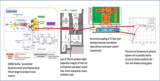
1. Introduction
2. Materials and Methods
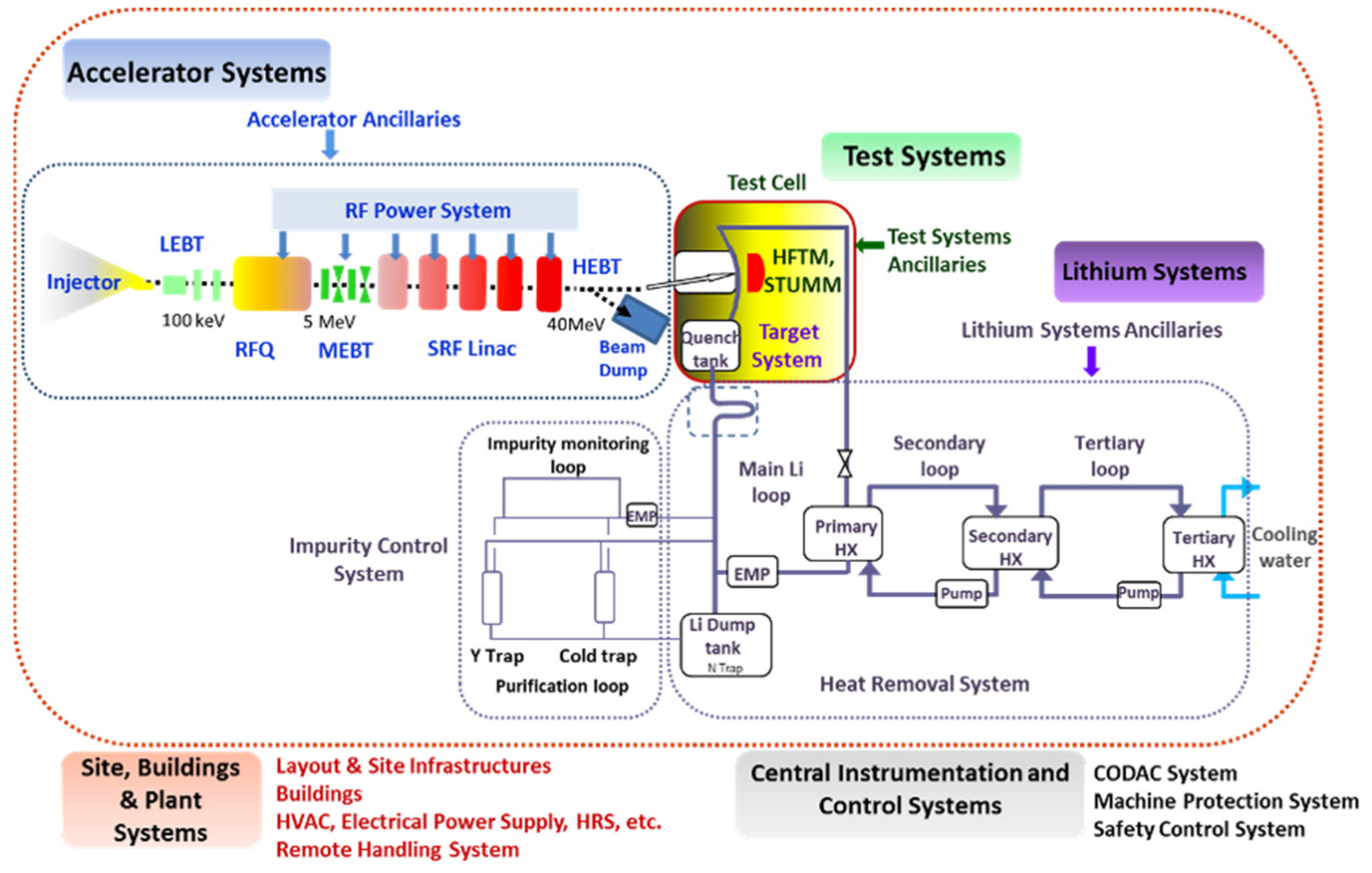
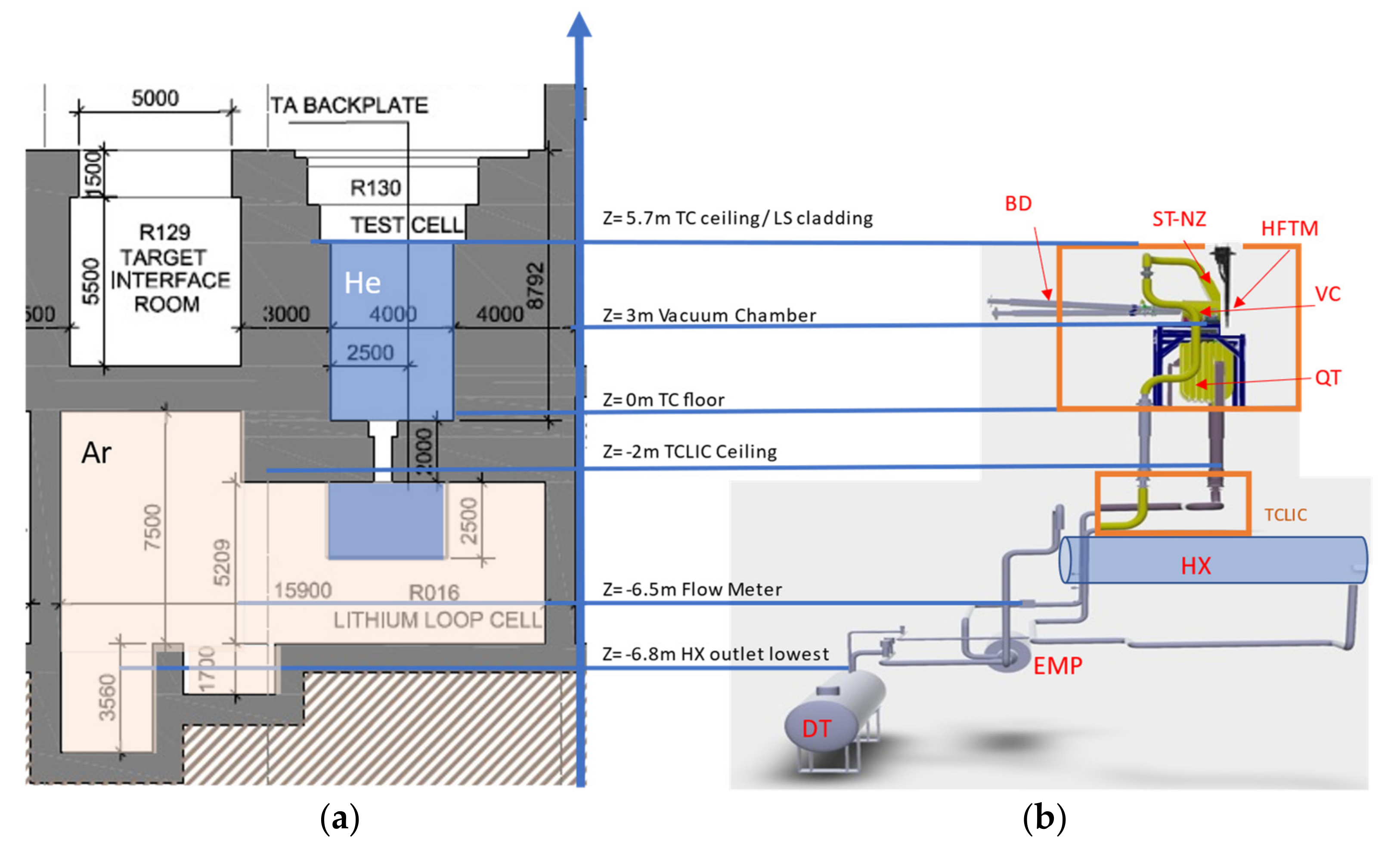
2.1. System Description
2.2. Accident Specification for the LTTC1 Event
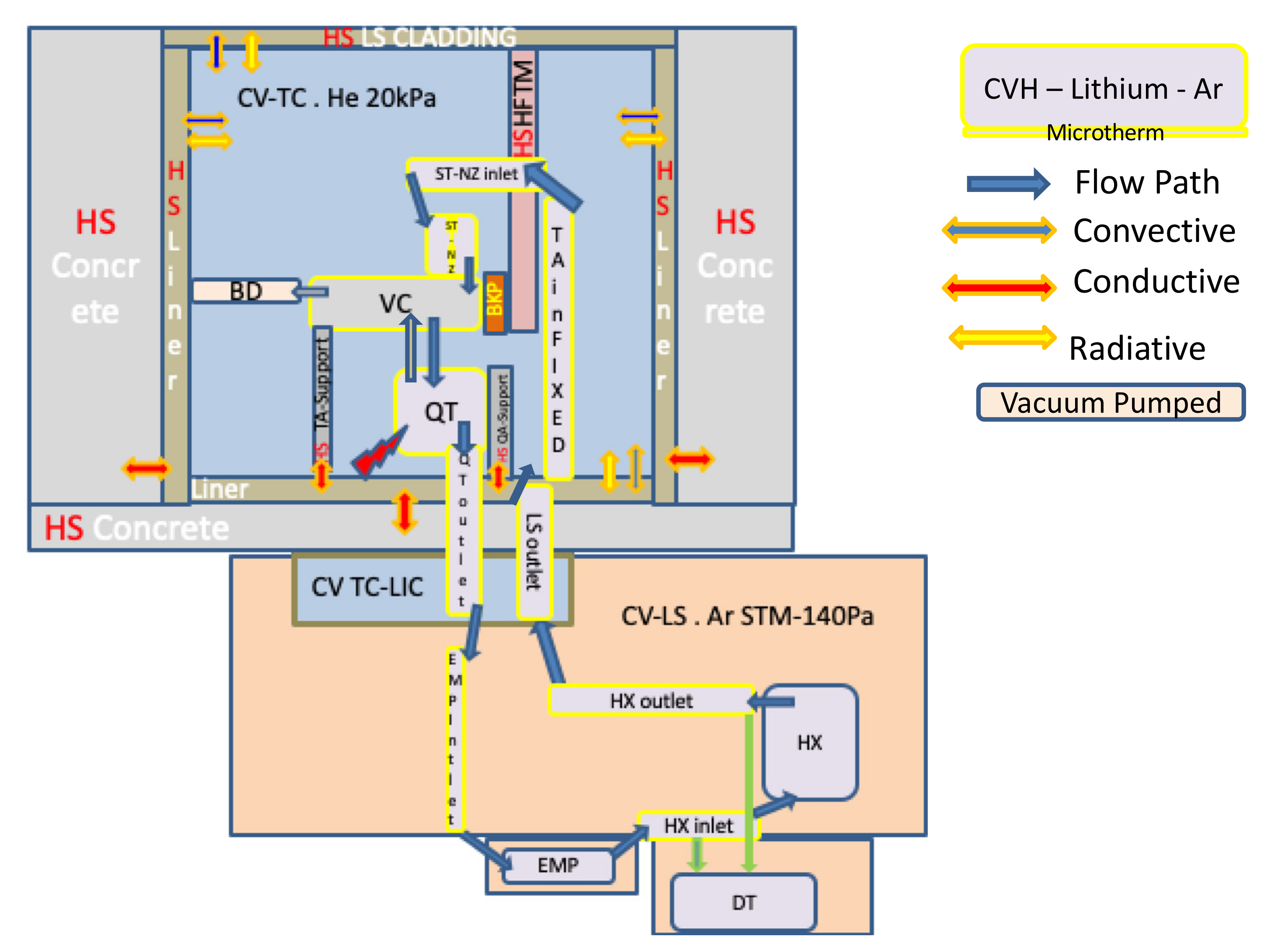
2.3. Simulation Models and Approaches
- Implement a MELCOR input deck to estimate the leaked lithium inventory, modeling TC, TA, and LS systems and using lithium as a working fluid.
- Implement a separate MELCOR model including the TC and TC-WCS systems to simulate TC wall cooling and using water as a working fluid.
- Implement a numerical coupling of the two models running in parallel and exchanging respective boundary conditions relative to the TC floor liner as an interfacing heat structure of interest.
2.3.1. Nodalization of TC and LS with the Lithium Working Fluid
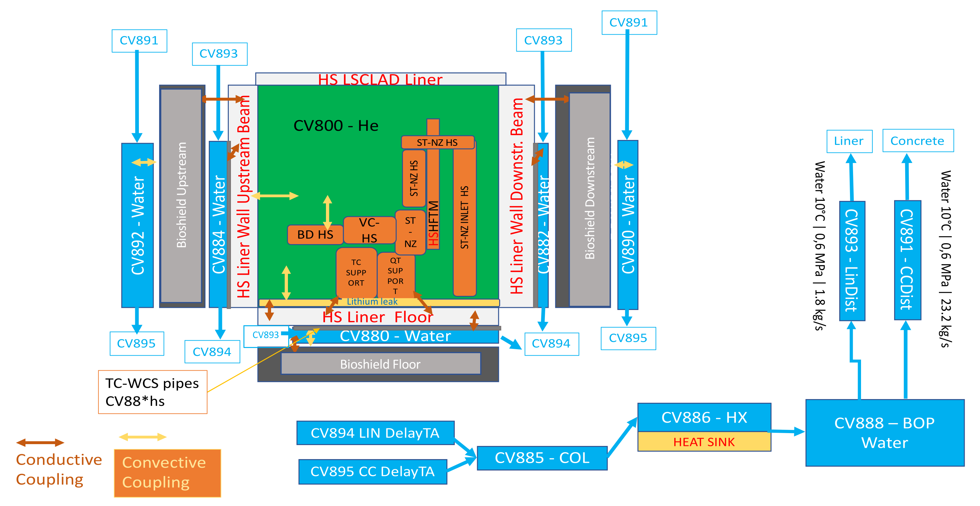
2.3.2. Nodalization of TC Walls Water Cooling Loop
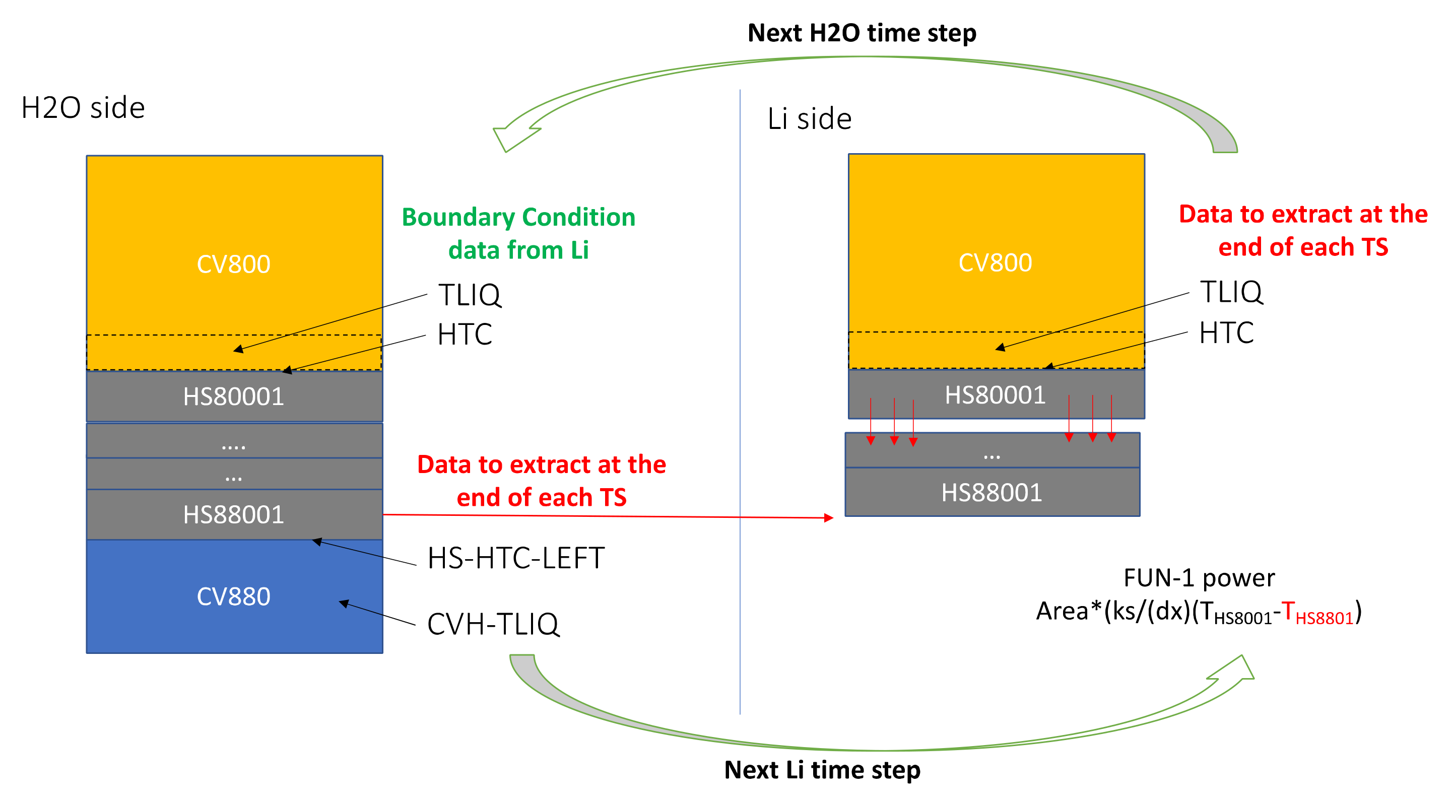
2.3.3. Numerical Coupling of the Two Models
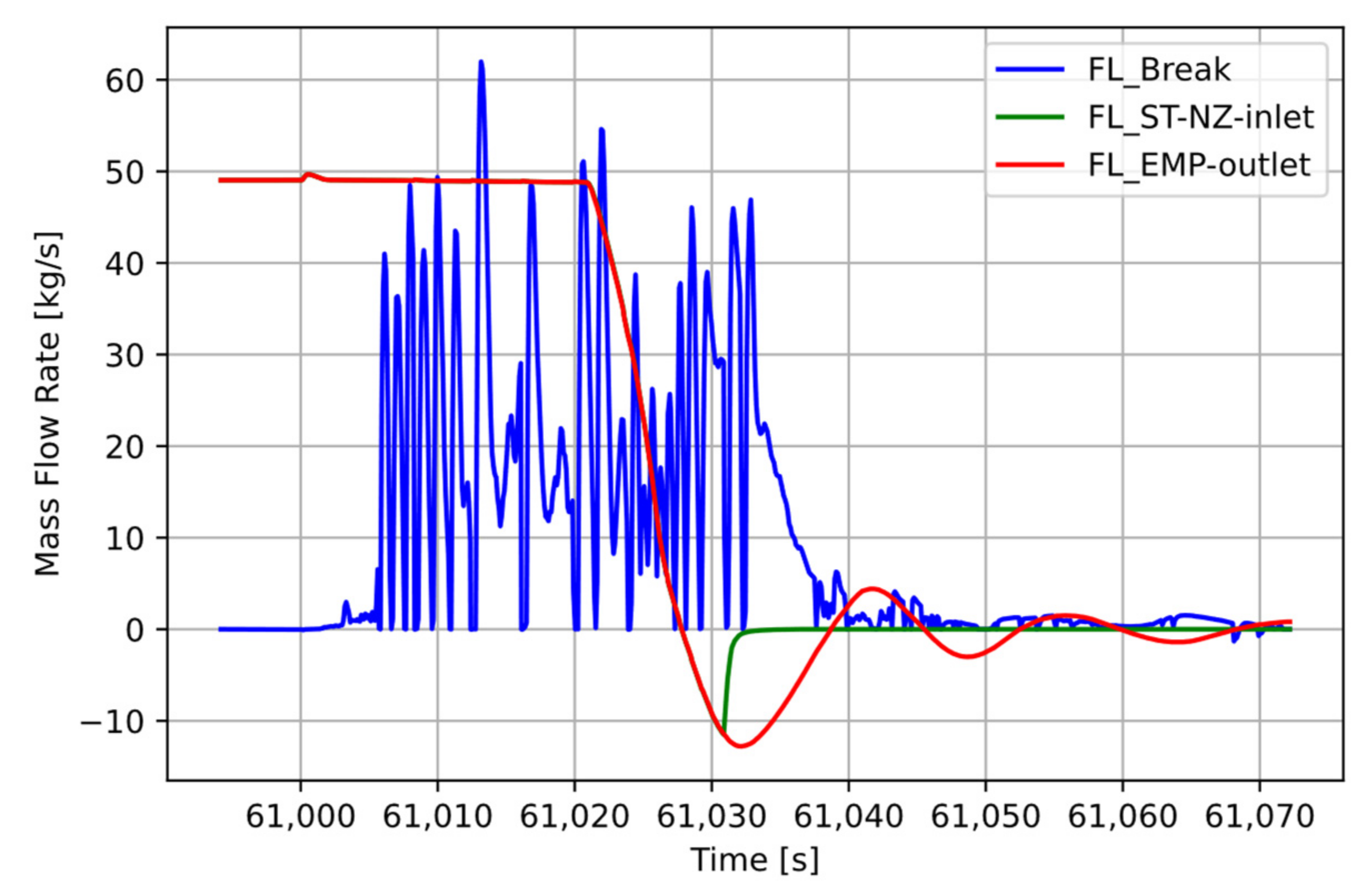
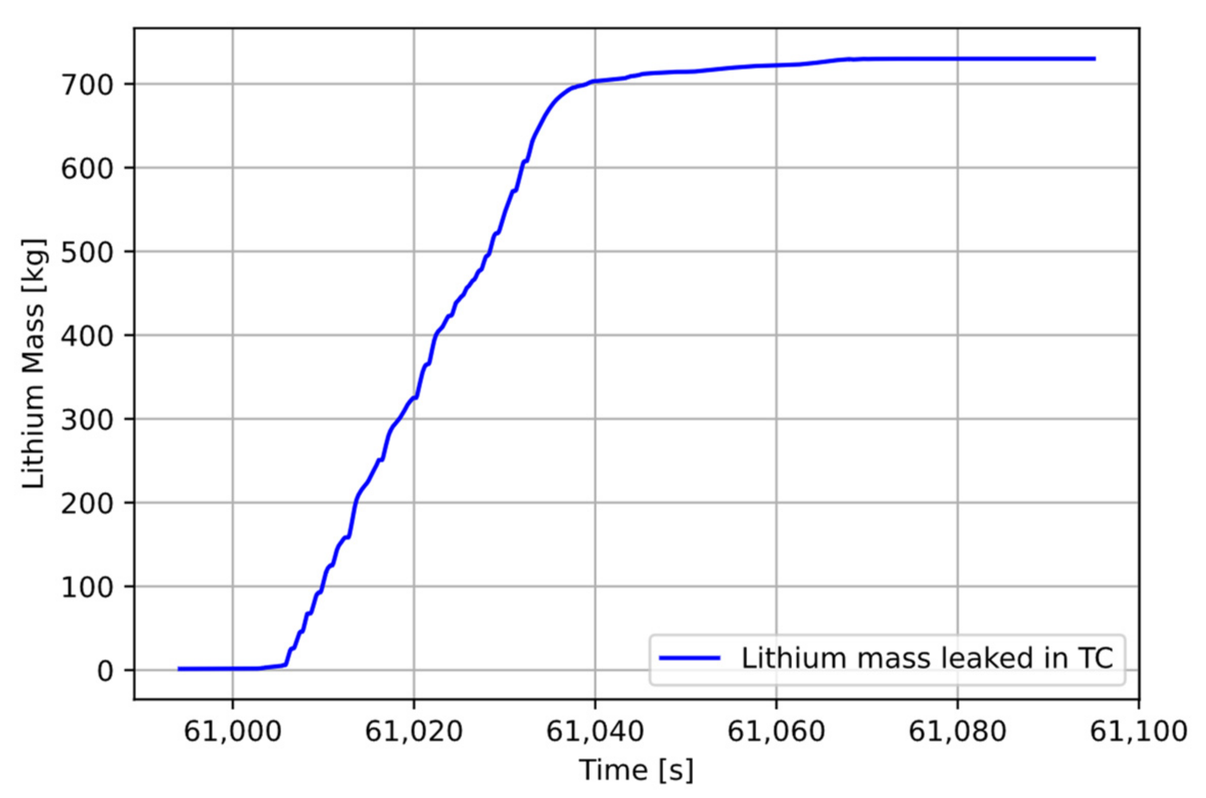
3. Results and Discussion
4. Conclusions
Author Contributions
Funding
Institutional Review Board Statement
Informed Consent Statement
Conflicts of Interest
Nomenclature
| BP | Back Plate |
| CV | Control Volume |
| EMP | Electromagnetic Pump |
| HEBT | High Energy Beam Transport. |
| HFTM | High Flux Test Module |
| HX | Heat Exchanger |
| LEBT | Low Energy Beam Transport |
| LS | Lithium System |
| LSP | Lower Shielding Plug |
| MEBT | Medium Energy Beam Transport |
| QT | Quench Tank |
| RFQ | Radiofrequency Quadrupoles |
| SRF | Superconducting Radiofrequency |
| ST-NZ | Straightener Nozzle |
| STUMM | Start-up Monitoring Module |
| TA | Target Assembly |
| TC-WCS | Test Cell Water Cooling System |
| TTC | Target Test Cell |
| VC | Vacuum Chamber |
References
- Linke, J.; Du, J.; Loewenhoff, T.; Pintsuk, G.; Spilker, B.; Steudel, I.; Wirtz, M. Challenges for plasma-facing components in nuclear fusion. Matter Radiat. Extrem. 2019, 4, 056201. [Google Scholar] [CrossRef]
- Federici, G.; Biel, W.; Gilbert, M.R.; Kemp, R.; Taylor, N.; Wenninger, R. European DEMO design strategy and consequences for materials. EURATOM Nucl. Fusion 2017, 57, 9. [Google Scholar] [CrossRef]
- Ibarra, A.; Arbeiter, F.; Bernardi, D.; Cappelli, M.; Garcia, A.; Heidinger, R.; Krolas, W.; Fischer, U.; Martin-Fuertes, F.; Micciché, G.; et al. The IFMIF-DONES project: Preliminary engineering design. Nucl. Fusion 2018, 58, 105002. [Google Scholar] [CrossRef]
- Federici, G.; Bachmann, C.; Barucca, L.; Biel, W.; Boccaccini, L.; Brown, R.; Bustreo, C.; Ciattaglia, S.; Cismondi, F.; Coleman, M.; et al. DEMO design activity in Europe: Progress and updates. Fusion Eng. Des. 2018, 136, 729–741. [Google Scholar] [CrossRef]
- Martín-Fuertes, F.; García, M.E.; Fernández, C.; D’Ovidio, G.; Pinna, T.; Porfiri, M.T.; Fischer, U.; Ogando, F.; Mota, F. Integration of Safety in IFMIF-DONES Design. Safety 2019, 5, 74. [Google Scholar] [CrossRef]
- D’Ovidio, G.; Martín-Fuertes, F. Accident analysis with MELCOR-fusion code for DONES lithium loop and accelerator. Fusion Eng. Des. 2019, 146, 473–477. [Google Scholar] [CrossRef]
- Arena, P.; Di Maio, P.A.; Nitti, F.S. Safety analysis of the dones primary heat removal system. Fusion Eng. Des. 2020, 161, 112002. [Google Scholar] [CrossRef]
- Piet, S.; Jeppson, D.; Muhlestein, L.; Kazimi, M.; Corradini, M. Liquid metal chemical reaction safety in fusion facilities. Fusion Eng. Des. 1987, 5, 273–298. [Google Scholar] [CrossRef]
- Barnett, S.; Kazimi, M.J. Consequences of a Lithium Spill in-Side the Containment and Vacuum Torus of a Fusion Reactor; PFC/RR-87-9; MIT Plasma Fusion Center: Cambridge, MA, USA, 1987. [Google Scholar]
- Merrill, B.J. A lithium-air reaction model for the melcor code for analyzing lithium fires in fusion reactors. Fusion Eng. Des. 2001, 54, 485–493. [Google Scholar] [CrossRef]
- Dongiovanni, D.N.; Porfiri, M.T. Exploratory fire analysis in DONES lithium system. Fusion Eng. Des. 2020, 156, 111680. [Google Scholar] [CrossRef]
- Merrill, B.J.; Humrickhouse, P.; Moore, R.L. A recent version of MELCOR for fusion safety applications. Fusion Eng. Des. 2010, 85, 1479–1483. [Google Scholar] [CrossRef]
- Merrill, B.J.; Humrickhouse, P.; Shimada, M. Recent development and application of a new safety analysis code for fusion reactors. Fusion Eng. Des. 2016, 109–111, 970–974. [Google Scholar] [CrossRef]
- Gauntt, R.O.; Cash, J.E.; Cole, R.K.; Erickson, C.M.; Humphries, L.L.; Rodriguez, S.B.; Young, M.F. MELCOR Computer Code Manuals Vol. 1: Primer and Users; Guide Version 1.8.6, NUREG/CR-6119, Volume 1, Rev. 3; Sandia National Laboratory: Princeton, NJ, USA, 2005. [Google Scholar]
- Arbeiter, F.; Diegele, E.; Fischer, U.; Garcia, A.; Ibarra, A.; Molla, J.; Mota, F.; Möslang, A.; Qiu, Y.; Serrano, M.; et al. Planned material irradiation capabilities of IFMIF-DONES. Nucl. Mater. Energy 2018, 16, 245–248. [Google Scholar] [CrossRef]
- Tian, K.; Ahedo, B.; Arbeiter, F.; Barrera, G.; Ciupinski, L.; Dézsi, T.; Horne, J.; Kovács, D.; Molla, J.; Mota, F.; et al. Overview of the current status of IFMIF-DONES test cell biological shielding design. Fusion Eng. Des. 2018, 136, 628–632. [Google Scholar] [CrossRef]
- Nitti, F.; Ibarra, A.; Ida, M.; Favuzza, P.; Furukawa, T.; Groeschel, F.; Heidinger, R.; Kanemura, T.; Knaster, J.; Kondo, H.; et al. The design status of the liquid lithium target facility of IFMIF at the end of the engineering design activities. Fusion Eng. Des. 2015, 100, 425–430. [Google Scholar] [CrossRef]
- Arena, P.; Bernardi, D.; Di Maio, P.A.; Frisoni, M.; Gordeev, S.; Miccichè, G.; Nitti, F.S.; Ibarra, A. The design of the DONES lithium target system. Fusion Eng. Des. 2019, 146, 1135–1139. [Google Scholar] [CrossRef]
- Simon, S.; Dézsi, T.; Arbeiter, F.; Tóth, M.; Castellanos, J.; Ibarra, A. Thermal-hydraulic simulation of IFMIF-DONES Test Cell atmosphere. Fusion Eng. Des. 2021, 167, 112336. [Google Scholar] [CrossRef]
- Merrill, B.J. ‘Recent Updates to the MELCOR 1.8.2 Code for ITER Applications,’ INL/EXT-07-12493, May 2007. Available online: https://inldigitallibrary.inl.gov/sites/sti/sti/3644018.pdf (accessed on 30 September 2021).
- Merrill, B.; Moore, R.; Polkinghorne, S.; Petti, D. Modifications to the MELCOR code for application in fusion accident analyses. Fusion Eng. Des. 2000, 51–52, 555–563. [Google Scholar] [CrossRef]
- Topilski, L.; Masson, X.; Porfiri, M.; Pinna, T.; Sponton, L.-L.; Andersen, J.; Takase, K.; Kurihara, R.; Sardain, P.; Girard, C. Validation and benchmarking in support of ITER-FEAT safety analysis. Fusion Eng. Des. 2001, 54, 627–633. [Google Scholar] [CrossRef]
- Moore, R.L. Status Report on an ITER ITA on Comparison of MELCOR 1.8.5 Results to MELCOR 1.8.2 Results for a Selected Set of Accident Analysis Cases Relevant to ITER FEAT; EDF-5470, Rev. 11; Idaho National Laboratory: Idaho Falls, ID, USA, 2003. [Google Scholar]
- Merrill, B.J. Benchmarking MELCOR 1.8.2 for ITER Against Recent EVITA Results; Idaho National Laboratory: Idaho Falls, ID, USA, 2007. [Google Scholar] [CrossRef]
- Sallus, L.; Van Hove, W. MELCOR Code Validation on HE-FUS3. Loop 2008, 391–404. [Google Scholar] [CrossRef]
- Merrill, B.J.; Humrickhouse, P.W.; Moore, R.L. “A Comparison of Modifications to MELCOR Versions 1.8.2 and 1.8.6 for ITER Safety Analysis”, INL/EXT-09-16715, June 2010. Available online: https://inldigitallibrary.inl.gov/sites/sti/sti/4536702.pdf (accessed on 30 September 2021).
- Reyes, S.; Topilski, L.; Taylor, N.; Merrill, B.J.; Sponton, L.-L. Updated Modeling of Postulated Accident Scenarios in ITER. Fusion Sci. Technol. 2009, 56, 789–793. [Google Scholar] [CrossRef]
- Dongiovanni, D.N.; Pinna, T.; Porfiri, M.T. DEMO Divertor preliminary safety assessment. Fusion Eng. Des. 2021, 169, 112475. [Google Scholar] [CrossRef]
- Jin, X.Z. BB LOCA analysis for the reference design of the EU DEMO HCPB blanket concept. Fusion Eng. Des. 2018, 136, 958–963. [Google Scholar] [CrossRef]
- D’Onorio, M.; Giannetti, F.; Caruso, G.; Porfiri, M.T. In-box LOCA accident analysis for the European DEMO water-cooled reactor. Fusion Eng. Des. 2019, 146, 732–735. [Google Scholar] [CrossRef]
- Gonfiotti, B.; Paci, S. Normal and Accidental Scenarios Analyses with MELCOR 1.8.2 and MELCOR 2.1 for the DEMO Helium-Cooled Pebble Bed Blanket Concept. Sci. Technol. Nucl. Install. 2015, 2015, 1–9. [Google Scholar] [CrossRef]
- Moon, S.; Sung, B.; Bang, I.C. Thermal Hydraulic Analysis of K-DEMO Single Blanket Module for Preliminary Accident Analysis using MELCOR. In Proceedings of the KNS 2016 Spring Meeting, Jeju, Korea, 12 May 2016. [Google Scholar]
- Murgatroyd, J.T.; Owen, S.; Grief, A.; Panayotov, D.; Saunders, C. Qualification of MELCOR and RELAP5 models for EU HCPB TBS accident analyses. Fusion Eng. Des. 2017, 124, 1251–1256. [Google Scholar] [CrossRef]
- Dobromir Panayotov Brad, J. Merrill, From Fission Nuclear Power Plants to Fusion Power Plant Safety Accident Analyses Challenges. In Proceedings of the 1st International Workshop on Environmental, Safety and Economic Aspects of Fusion Power, Jeju, Korea, 13 September 2015. [Google Scholar] [CrossRef]
- Pena, A.; Esteban, G.; Sancho, J.; Kolesnik, V.; Abánades, A. Hydraulics and heat transfer in the IFMIF liquid lithium target: CFD calculations. Fusion Eng. Des. 2009, 84, 1479–1483. [Google Scholar] [CrossRef][Green Version]
- Gordeev, S.; Gröschel, F.; Heinzel, V.; Hering, W.; Stieglitz, R. Numerical study of the flow conditioner for the IFMIF liquid lithium target. Fusion Eng. Des. 2014, 89, 1751–1757. [Google Scholar] [CrossRef]
- Gordeev, S.; Gröschel, F.; Heinzel, V.; Hering, W.; Stieglitz, R. Numerical Analysis of Unsteady Flow Behavior in Flow Conditioner of IFMIF Liquid-Lithium Target. Fusion Sci. Technol. 2015, 68, 618–624. [Google Scholar] [CrossRef]
- Gordeev, S.; Arena, P.; Bernardi, D.; Di Maio, P.A.; Nitti, F.S. Analytical and Numerical Assessment of Thermally Induced Pressure Waves in the IFMIF-DONES Liquid-Lithium Target. IEEE Trans. Plasma Sci. 2020, 48, 1485–1488. [Google Scholar] [CrossRef]
- Tolli, J.E. Overview of Property Formulations for Helium, Nitrogen, Lithium, and Lithium-Lead in ATHENA/MOD1 with Comparison of Calculated Properties to Measured Properties, EGG-FSP-10245, Idaho National Engineering Laboratory, April 1992. Available online: https://ui.adsabs.harvard.edu/abs/1992opfh.rept.....T/abstract (accessed on 30 September 2021).
- Merrill, B.J. Modifications Made to the MELCOR Code for Analyzing Lithium Fires in Fusion Reactors, INEEL/EXT-2000-00489, April 2000. Available online: https://www.osti.gov/biblio/764178-modifications-made-melcor-code-analyzing-lithium-fires-fusion-reactors (accessed on 30 September 2021).
- Jeppson, D.W.; Scoping, D.W. Studies: Behavior and control of lithium and lithium aerosols. HEDLTME 1982, 79–80. [Google Scholar] [CrossRef]
- Jeppson, D.W. Results and Code Prediction Comparisons of Lithium-Air Reaction and Aerosol Behavior Tests; HEDL-TME 85–25; Hanford Engineering Development Laboratory: Richland, WA, USA, 1986; Available online: https://inis.iaea.org/search/searchsinglerecord.aspx?recordsFor=SingleRecord&RN=18000591 (accessed on 30 September 2021).
- Merrill, B.; Humrickhouse, P.; Yoon, S.-J. Modifications to the MELCOR-TMAP code to simultaneously treat multiple fusion coolants. Fusion Eng. Des. 2018, 146, 289–292. [Google Scholar] [CrossRef]
- Qiu, Y.; Arbeiter, F.; Fischer, U.; Tian, K. Neutronics analyses for the bio-shield and liners of the IFMIF-DONES test cell. Fusion Eng. Des. 2019, 146, 723–727. [Google Scholar] [CrossRef]
- Frisoni, M.; Bernardi, D.; Nitti, F. Nuclear assessment of the IFMIF-DONES lithium target system. Fusion Eng. Des. 2020, 157, 111658. [Google Scholar] [CrossRef]
- Marsh, D.J. A Thermal Shock Fatigue Study of Type 304 and 316 Stainless Steels; UKAEA Risley Nuclear Power Development Establishment (ND-R--606(S)): London, UK, 1982. [Google Scholar]
- Bernard, L.J.; Lamain, G.L.; Verzeletti, G. Crack Initiation and Growth in Stainless Steel Tubes under Thermal Shocks; Radon, J.C., Ed.; Fracture and Fatigue: Pergamon, Turkey, 1980; pp. 391–400. ISBN 9780080261614. [Google Scholar] [CrossRef]
- D’Onorio, M.; Giannetti, F.; Porfiri, M.T.; Caruso, G. Preliminary sensitivity analysis for an ex-vessel LOCA without plasma shutdown for the EU DEMO WCLL blanket concept. Fusion Eng. Des. 2020, 158, 111745. [Google Scholar] [CrossRef]


| Lithium Inventory | Description | Length [m] | Vol [m3] |
|---|---|---|---|
| Piping primary loop | Pipe LS—TLIC | 14.7 | 0.27 |
| Pipe LS—EMP outlet | 13.1 | 0.24 | |
| Pipe LS—HX outlet | 17.7 | 0.33 | |
| Pipe LS outlet—TLIC | 17.6 | 0.33 | |
| Pipe LS—TLIC-LSRoom | 8.4 | 0.16 | |
| Piping target assembly | ST-NZ Inlet Fixed pipe | 5.8 | 0.11 |
| ST-NZ Inlet Removable pipe | 2.2 | 0.04 | |
| Equipment | ST-NZ | 0.06 | |
| QT | 1.20 | ||
| EMP | 0.52 | ||
| HX | 4.10 | ||
| DT | 9 * | ||
| Total | 7.4 |
| Description | Material | Equivalent Thickness [m] | Surface [m2] | Initial Temperature [K] | Nuclear Heating [W] | Decay Heat [W] |
|---|---|---|---|---|---|---|
| Liner Floor (HS80001) | Stainless Steel | 0.008 | 8.4 | 283.15 | 373.0 | 8.0 |
| Bioshield Floor | Concrete | 2.0 | 8.4 | 313.0 | 3701.0 | 74.0 |
| Liner Wall downstream beam | Stainless Steel | 0.008 | 33.1 | 283.15 | 4308.0 | 86.0 |
| Liner Wall upstream beam | Stainless Steel | 0.008 | 45.8 | 283.15 | 2532.0 | 50.0 |
| Bioshield wall downstream beam | Concrete | 1.0 | 33.1 | 293.15 | 56.0 | 1123.0 |
| Bioshield wall upstream beam | Concrete | 1.0 | 45.8 | 322.15 | 27.0 | 546.0 |
| LSP Cladding | Stainless Steel | 0.008 | 11.2 | 333.0 | ||
| HFTM | Eurofer | 0.11 | 1.15 | 349.0 | ||
| Backplate | Eurofer | 0.03 | 523. | 1085.0 | 22.0 | |
| Qt Support | Stainless Steel | 0.01 | 3.51 | 353.0 | 400.0 | 32.0 |
| Tc Support | Stainless Steel | 0.01 | 14.482 | 353.0 | 1448.0 | 116.0 |
| Description | CV | Pool P [Pa] | Pool Temperature [K] | Volume [m3] |
|---|---|---|---|---|
| Floor Liner cooling branch | 880 | 3.50 × 10⁵ | 3.50 × 10⁵ | 4.5 × 10⁻³ |
| Downstream liner cooling branch | 882 | 5.80 × 10⁵ | 5.80 × 10⁵ | 2.89 × 10⁻² |
| Upstream liner cooling branch | 884 | 4.00 × 10⁵ | 4.00 × 10⁵ | 3.85 × 10⁻² |
| Main Collector | 885 | 1.50 × 10⁵ | 1.50 × 10⁵ | 1.06 |
| Heat Exchanger | 886 | 1.50 × 10⁵ | 1.50 × 10⁵ | 7.50 |
| Pressurizer | 887 | 1.50 × 10⁵ | 1.50 × 10⁵ | 1.40 |
| Balance volume | 888 | 6.00 × 10⁵ | 6.00 × 10⁵ | 6.00 |
| Downstream Bioshield cooling branch | 890 | 5.80 × 10⁵ | 5.80 × 10⁵ | 1.23 × 10⁻¹ |
| Bioshield branch distributor | 891 | 1.00 | ||
| Upstream Bioshield cooling branch | 892 | 3.50 × 10⁵ | 3.50 × 10⁵ | 1.23 × 10⁻¹ |
| Liner branch distributor | 893 | 6.00 × 10⁵ | 6.00 × 10⁵ | 1.00 |
| Liner Cooling branch delay tank | 894 | 1.50 × 10⁵ | 1.50 × 10⁵ | 1.00 |
| Concrete Cooling branch delay tank | 895 | 1.50 × 10⁵ | 1.50 × 10⁵ | 1.00 |
| Sensor | Triggering Condition | Time of Occurrence Since PIE [s] |
|---|---|---|
| Target Vacuum Chamber Gas Pressure | TCpressure ≥ 1 kPa (approx. 10 × nominal pressure) | 0.22 |
| Pressure in TC | Increase 10% with respect to nominal | 2 |
| Temperature in TC liner | Liner Floor Temperature > 393 K (100 K over nominal) | 13.0 |
| Quench Tank Li-Level | QTlevel ≤ 0.715 m (50% nominal value) | 21.9 |
Publisher’s Note: MDPI stays neutral with regard to jurisdictional claims in published maps and institutional affiliations. |
© 2021 by the authors. Licensee MDPI, Basel, Switzerland. This article is an open access article distributed under the terms and conditions of the Creative Commons Attribution (CC BY) license (https://creativecommons.org/licenses/by/4.0/).
Share and Cite
Dongiovanni, D.N.; D’Onorio, M. Loss of Liquid Lithium Coolant in an Accident in a DONES Test Cell Facility. Energies 2021, 14, 6569. https://doi.org/10.3390/en14206569
Dongiovanni DN, D’Onorio M. Loss of Liquid Lithium Coolant in an Accident in a DONES Test Cell Facility. Energies. 2021; 14(20):6569. https://doi.org/10.3390/en14206569
Chicago/Turabian StyleDongiovanni, Danilo Nicola, and Matteo D’Onorio. 2021. "Loss of Liquid Lithium Coolant in an Accident in a DONES Test Cell Facility" Energies 14, no. 20: 6569. https://doi.org/10.3390/en14206569
APA StyleDongiovanni, D. N., & D’Onorio, M. (2021). Loss of Liquid Lithium Coolant in an Accident in a DONES Test Cell Facility. Energies, 14(20), 6569. https://doi.org/10.3390/en14206569