
Investigation of Thermoplastic Polyurethane Finger Cushion with Magnetorheological Fluid for Soft-Rigid Gripper


Abstract
:1. Introduction
2. Materials and Methods
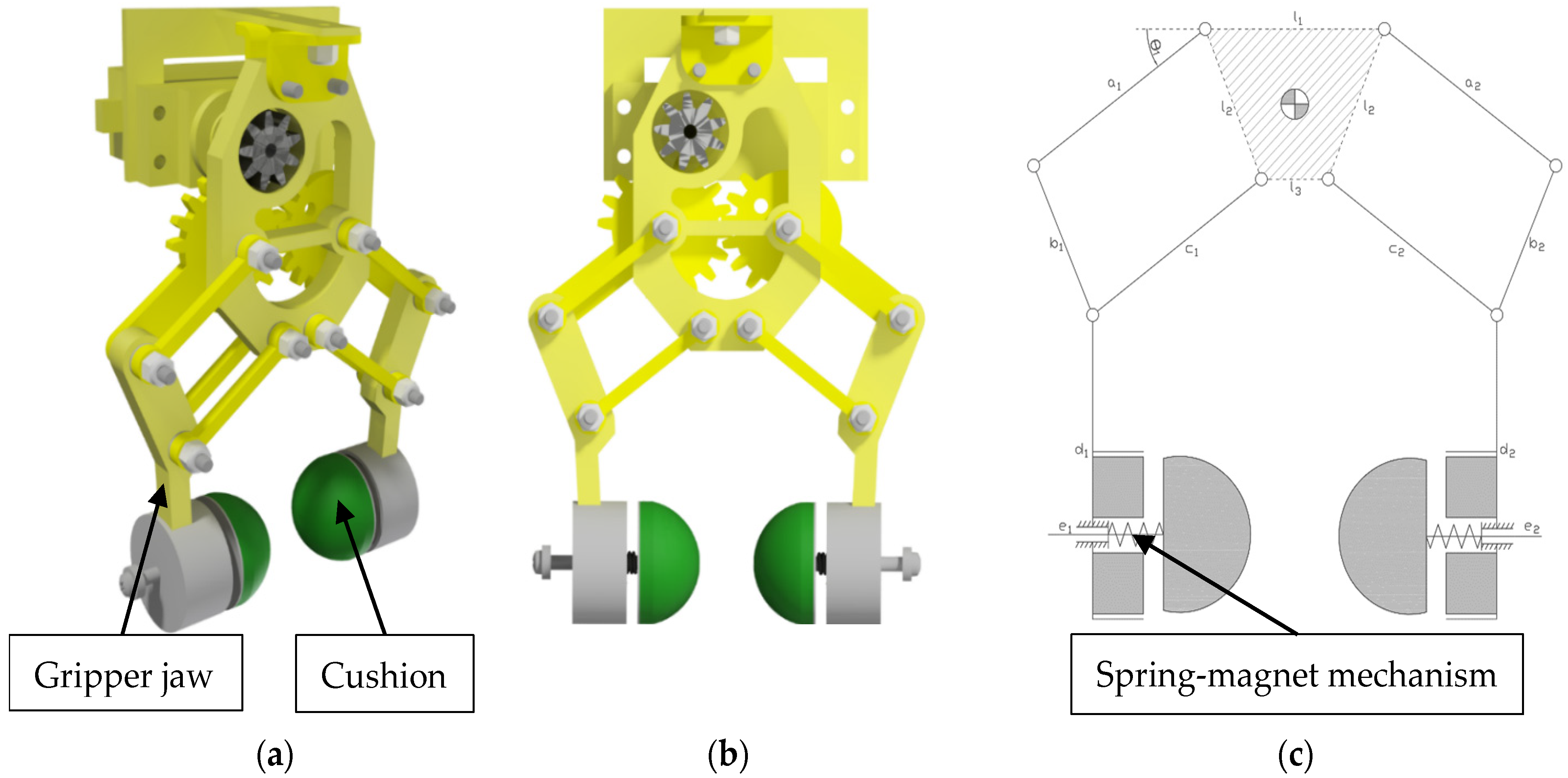
2.1. Cushion Structure
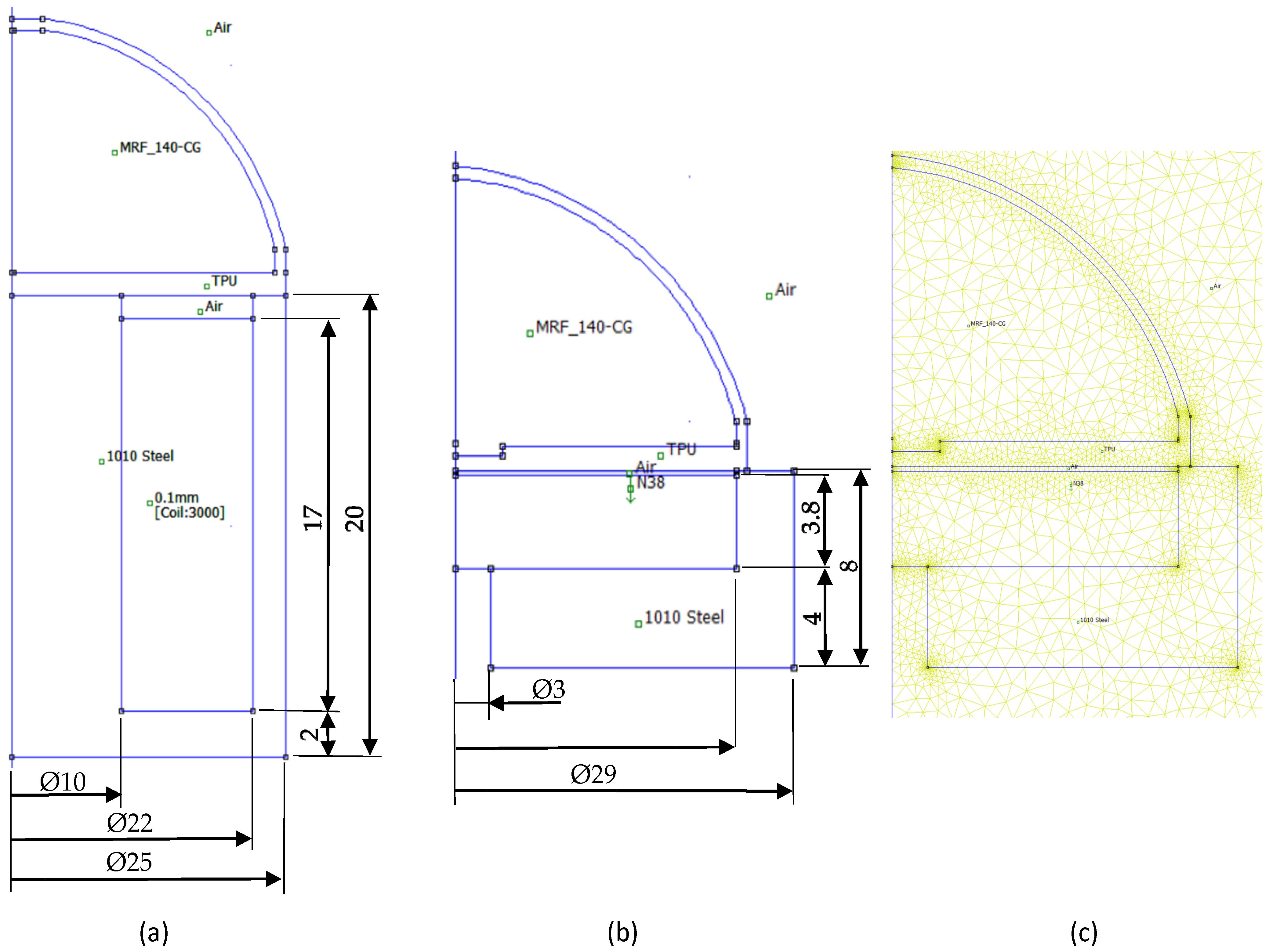
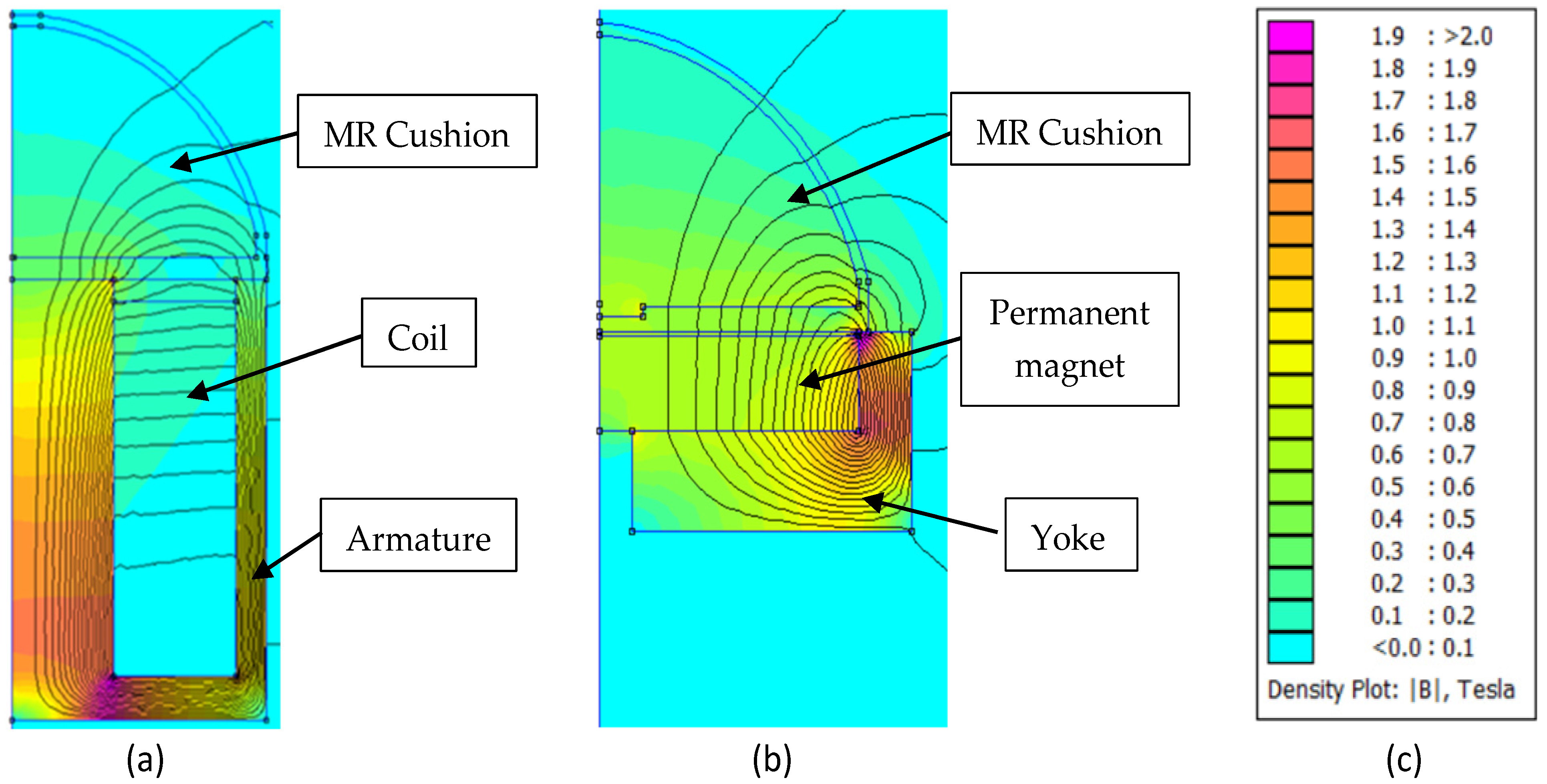
2.2. Preliminary FEA
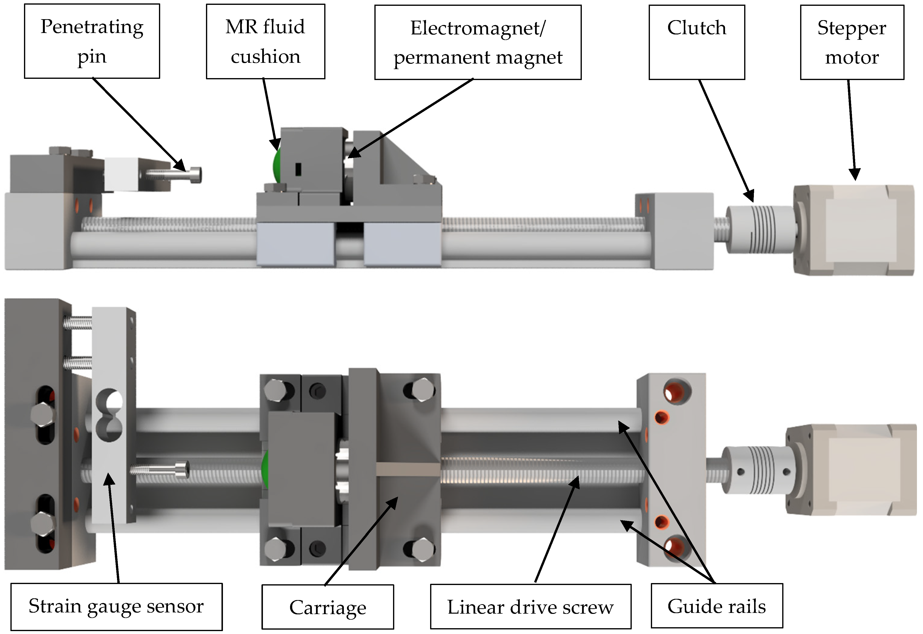
2.3. The Test Stand for the Investigations of a Pin Penetration into the Cushion
3. Results
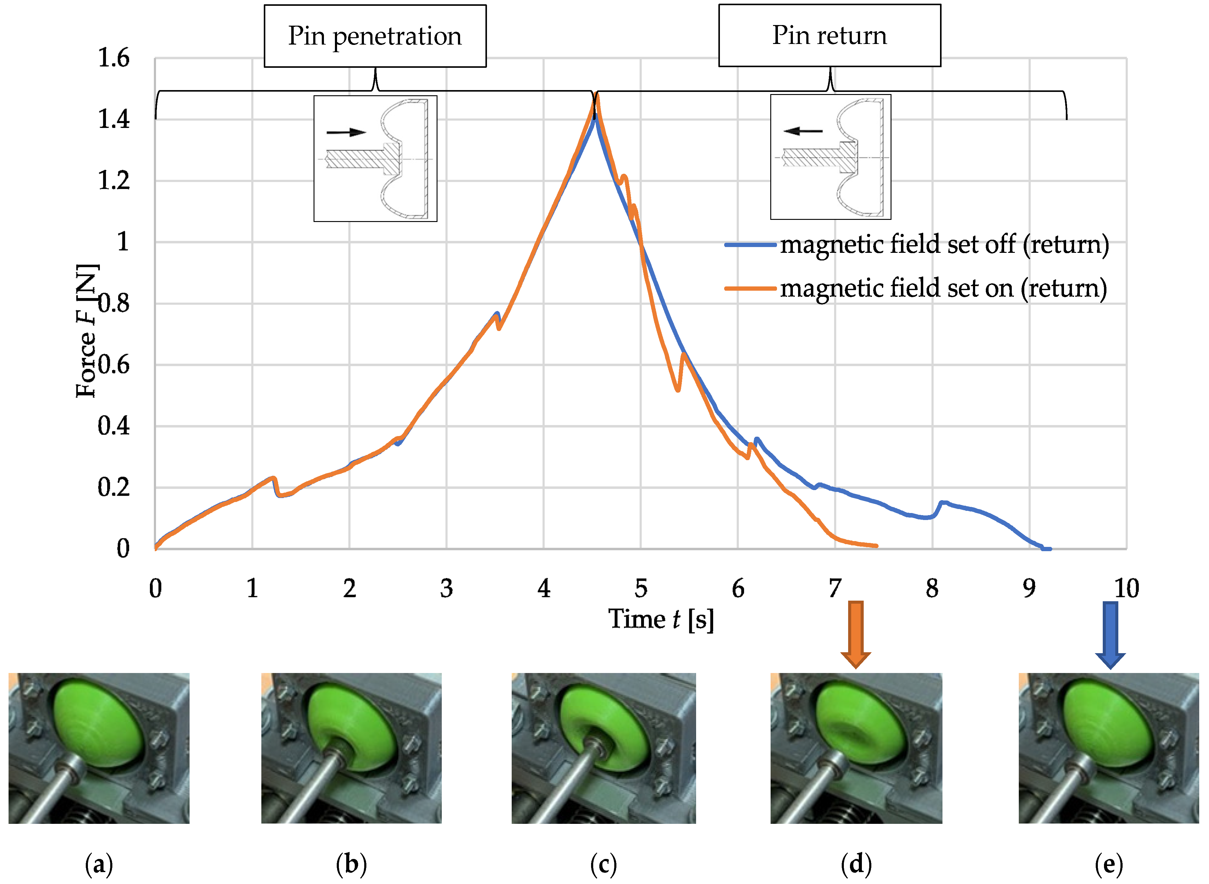
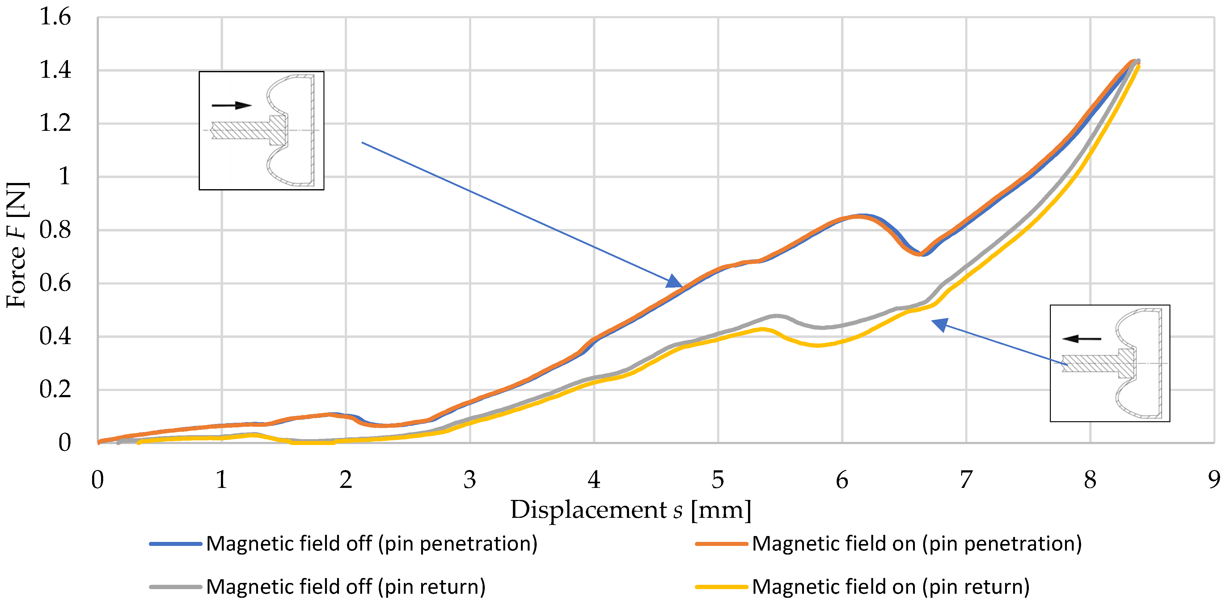
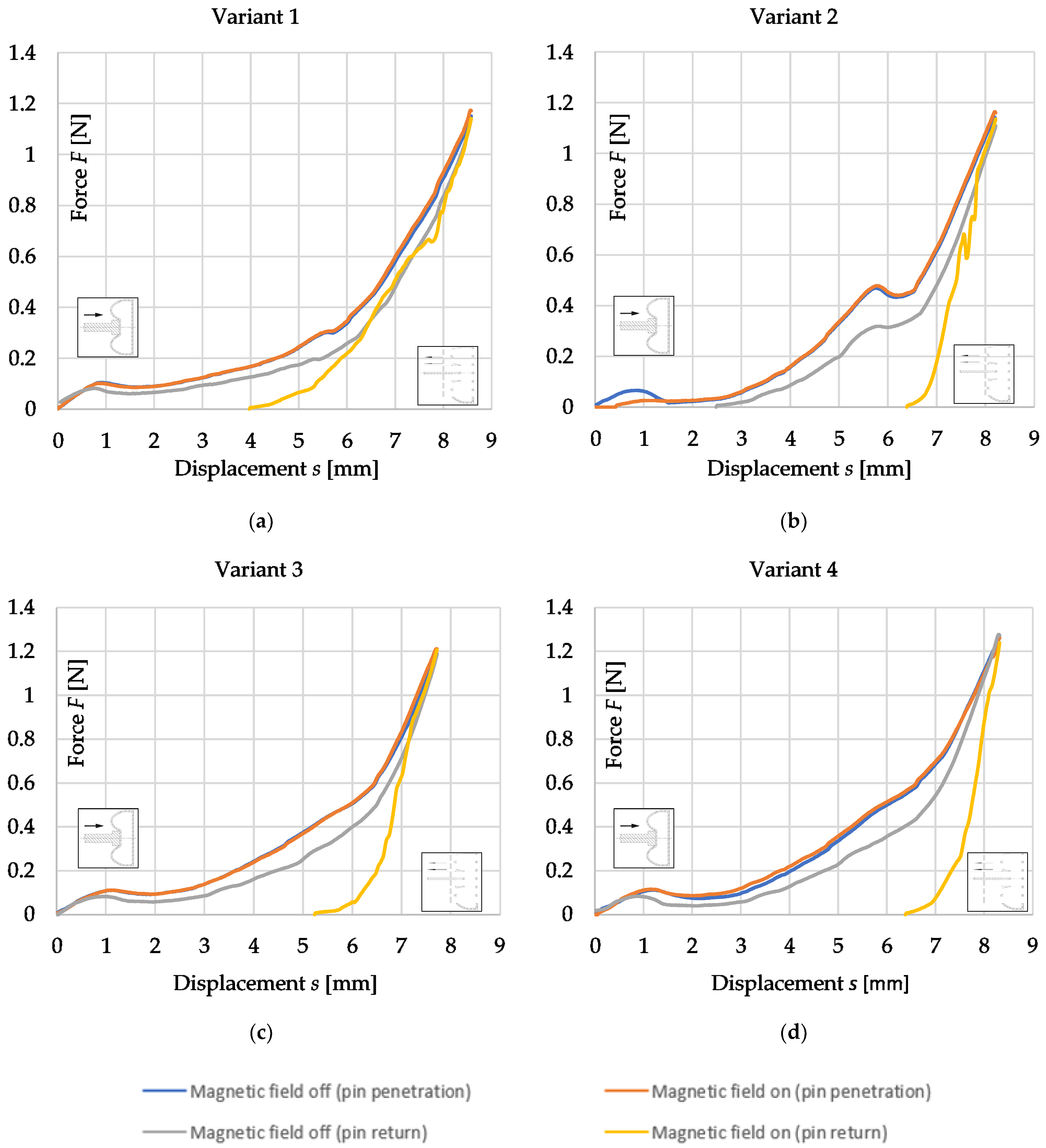
3.1. Pin Penetration and Return Test Results
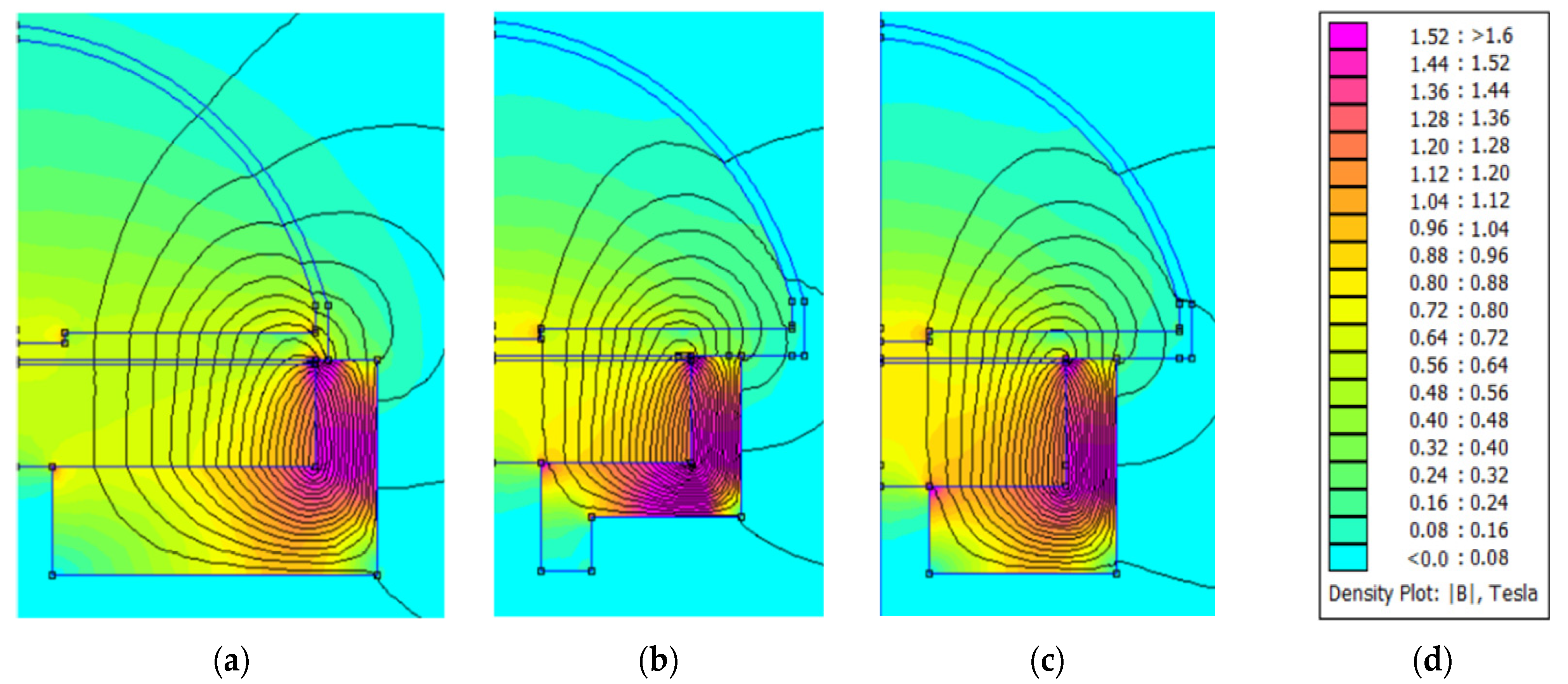
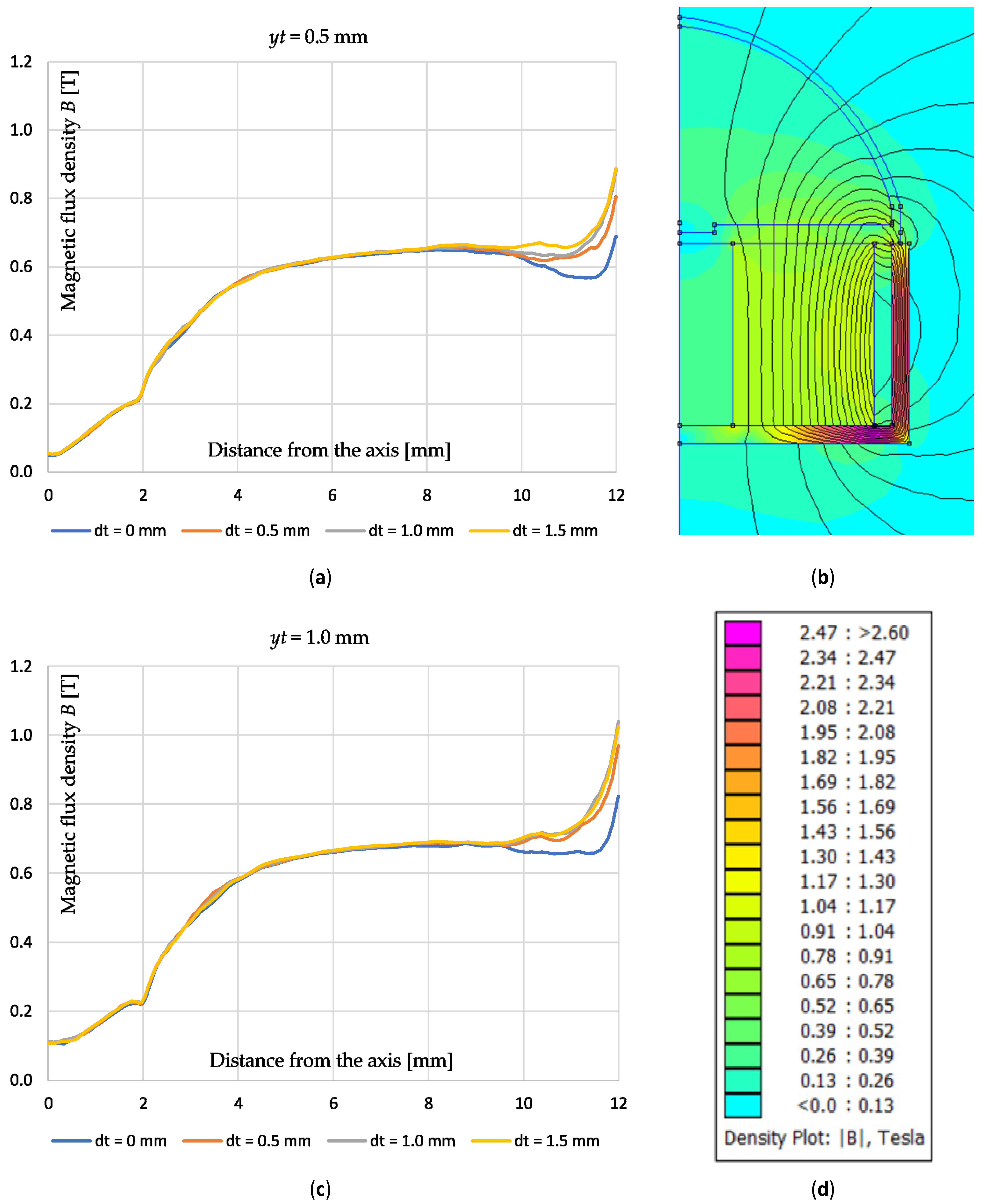
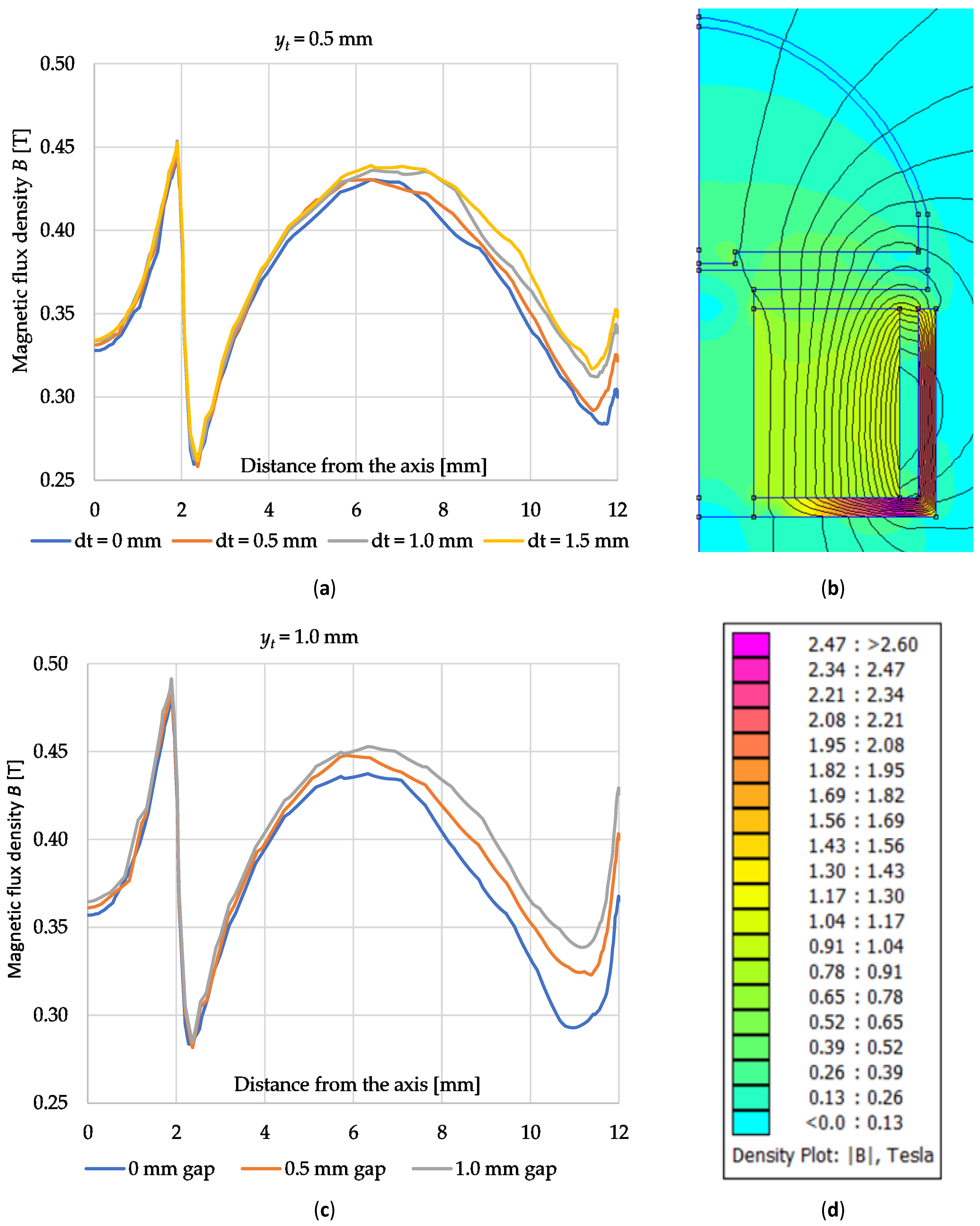
3.2. FEA of Magnetic Field Excitation System
4. Discussion
5. Conclusions
6. Patents
Author Contributions
Funding
Institutional Review Board Statement
Informed Consent Statement
Data Availability Statement
Conflicts of Interest
References
- Terrile, S.; Argüelles, M.; Barrientos, A. Comparison of Different Technologies for Soft Robotics Grippers. Sensors 2021, 21, 3253. [Google Scholar] [CrossRef]
- Cramer, J.; Cramer, M.; Demeester, E.; Kellens, K. Exploring the potential of magnetorheology in robotic grippers. Procedia CIRP 2018, 76, 127–132. [Google Scholar] [CrossRef]
- Giannaccini, M.E.; Georgilas, I.; Horsfield, I.; Peiris, B.H.P.M.; Lenz, A.; Pipe, A.G.; Dogramadzi, S. A variable compliance, soft gripper. Auton. Robot. 2014, 36, 93–107. [Google Scholar] [CrossRef] [Green Version]
- Homberg, B.S.; Katzschmann, R.K.; Dogar, M.R.; Rus, D. Haptic identification of objects using a modular soft robotic gripper. In Proceedings of the IEEE/RSJ International Conference on IROS, Hamburg, Germany, 28 September–2 October 2015; pp. 1698–1705. [Google Scholar] [CrossRef] [Green Version]
- Calisti, M.; Arienti, A.; Renda, F.; Levy, G.; Hochner, B.; Mazzolai, B.; Dario, P.; Laschi, C. Design and development of a soft robot with crawling and grasping capabilities. In Proceedings of the IEEE International Conference on Robotics and Automation, Saint Paul, MN, USA, 14–18 May 2012; pp. 4950–4955. [Google Scholar] [CrossRef]
- Hughes, J.; Culha, U.; Giardina, F.; Guenther, F.; Rosendo, A.; Iida, F. Soft Manipulators and Grippers: A Review. Front. Robot. AI 2016, 3, 1–12. [Google Scholar] [CrossRef] [Green Version]
- Miron, G.; Bédard, B.; Plante, J.S. Sleeved Bending Actuators for Soft Grippers: A Durable Solution for High Force-to-Weight Applications. Actuators 2018, 7, 40. [Google Scholar] [CrossRef] [Green Version]
- Park, W.; Seo, S.; Bae, J. A hybrid gripper with soft material and rigid structures. IEEE Robot. Autom. Lett. 2019, 4, 65–72. [Google Scholar] [CrossRef]
- Cheng, P.; Jia, J.; Ye, Y.; Wu, C. Modeling of a Soft-Rigid Gripper Actuated by a Linear-Extension Soft Pneumatic Actuator. Sensors 2021, 21, 493. [Google Scholar] [CrossRef]
- Cho, K.J.; Koh, J.S.; Kim, S.; Chu, W.S.; Hong, Y.; Ahn, S.H. Review of manufacturing processes for soft biomimetic robots. Int. J. Precis. Eng. Manuf. 2009, 10, 171–181. [Google Scholar] [CrossRef]
- Cheng, N.G.; Gopinath, A.; Wang, L.; Iagnemma, K.; Hosoi, A.E. Thermally tunable, self-healing composites for soft robotic applications. Macromol. Mater. Eng. 2014, 299, 1279–1284. [Google Scholar] [CrossRef]
- Camarillo, D.B.; Milne, C.F.; Carlson, C.R.; Zinn, M.R.; Salisbury, J.K. Mechanics modeling of tendon-driven continuum manipulators. IEEE Trans. Robot. 2008, 24, 1262–1273. [Google Scholar] [CrossRef]
- Camarillo, D.B.; Carlson, C.R.; Salisbury, J.K. Configuration tracking for continuum manipulators with coupled tendon drive. IEEE Trans. Robot. 2009, 25, 798–808. [Google Scholar] [CrossRef]
- Amend, J.R.; Brown, E.; Rodenberg, N.; Jaeger, H.M.; Lipson, H. A positive pressure universal gripper based on the jamming of granular material. IEEE Trans. Robot. 2012, 28, 341–350. [Google Scholar] [CrossRef]
- Nishida, T.; Okatani, Y.; Tadakuma, K. Development of universal robot gripper using mr α fluid. Int. J. Hum. Robot. 2016, 13, 1–13. [Google Scholar] [CrossRef]
- Choi, Y.T.; Hartzell, C.M.; Leps, T.; Wereley, N.M. Gripping characteristics of an electromagnetically activated magnetorheological fluid-based gripper. AIP Adv. 2018, 8, 1–6. [Google Scholar] [CrossRef] [Green Version]
- Hartzell, C.M.; Choi, Y.T.; Wereley, N.M.; Leps, T.J. Performance of a magnetorheological fluid-based robotic end effector. Smart Mater. Struct. 2019, 28, 1–8. [Google Scholar] [CrossRef]
- Tsugami, Y.; Nishida, T. Simple structured gripper using electromagnet and permanent magnet. In Proceedings of the International Conference on ICT Robotics, Kagoshima, Japan, 25–26 November 2017; pp. 64–67. [Google Scholar]
- Maruyama, R.; Watanabe, T.; Uchida, M. Delicate grasping by robotic gripper with incompressible fluid-based deformable fingertips. In Proceedings of the IEEE/RSJ International Conference on Intelligent Robots and Systems, Tokyo, Japan, 3–7 November 2013; pp. 5469–5474. [Google Scholar] [CrossRef]
- Nishimura, T.; Suzuki, Y.; Tsuji, T.; Watanabe, T. Fluid pressure monitoring-based strategy for delicate grasping of fragile objects by a robotic hand with fluid fingertips. Sensors 2019, 19, 782. [Google Scholar] [CrossRef] [Green Version]
- Choi, H.; Koc, M. Design and feasibility tests of a flexible gripper based on inflatable rubber pockets. Int. J. Mach. Tools Manuf. 2006, 46, 1350–1361. [Google Scholar] [CrossRef]
- Tsugami, Y.; Barbié, T.; Tadakuma, K.; Nishida, T. Development of Universal Parallel Gripper Using Reformed Magnetorheological Fluid. In Proceedings of the 11th Asian control conference (ASCC) IEEE, Gold Coast, Australia, 17–20 December 2017; pp. 778–783. [Google Scholar] [CrossRef]
- Leddy, M.T.; Dollar, A.M. Examining the frictional behavior of primitive contact geometries for use as robotic finger pads. IEEE Robot. Autom. Lett. 2020, 5, 3137–3144. [Google Scholar] [CrossRef]
- Spiers, A.J.; Calli, B.; Dollar, A.M. Variable-friction finger surfaces to enable within-hand manipulation via gripping and sliding. IEEE Robot. Autom. Lett. 2018, 3, 4116–4123. [Google Scholar] [CrossRef]
- Costanzo, M.; De Maria, G.; Natale, C. Two-fingered in-hand object handling based on force/tactile feedback. IEEE Trans. Robot. 2019, 36, 157–173. [Google Scholar] [CrossRef]
- Białek, M.; Rybarczyk, D.; Milecki, A.; Nowak, P. Artificial hand controlled by a glove with a force feedback. In Advances in Manufacturing II; Volume 1—Solutions for Industry 4.0; Springer: Berlin/Heidelberg, Germany, 2019; pp. 444–455. [Google Scholar] [CrossRef]
- Rybarczyk, D.; Owczarek, P.; Myszkowski, A. Development of Force Feedback Controller For the Loader Crane. In Advances in Manufacturing—Lecture Notes in Mechanical Engineering; Springer: Berlin/Heidelberg, Germany, 2018; pp. 345–354. [Google Scholar] [CrossRef]
- Oh, J.-S.; Sohn, J.W.; Choi, S.-B. Material Characterization of Hardening Soft Sponge Featuring MR Fluid and Application of 6-DOF MR Haptic Master for Robot-Assisted Surgery. Materials 2018, 11, 1268. [Google Scholar] [CrossRef] [PubMed] [Green Version]
- Naimzad, A.; Ghodsi, M.; Hojjat, Y.; Maddah, A. MREs development and its application on miniature gripper. In Proceedings of the International Conference on Advanced Materials Engineering, Suntec, Singapore, 26 June–1 July 2011; Volume 15, pp. 75–79. [Google Scholar]
- Zhou, J.; Chen, S.; Wang, Z. A soft-robotic gripper with enhanced object adaptation and grasping reliability. IEEE Robot. Autom. Lett. 2017, 2, 2287–2293. [Google Scholar] [CrossRef]
- Finite Element Method Magnetics by David Meeker. Available online: https://www.femm.info/wiki/HomePage (accessed on 18 March 2021).
- LORD MR Fluid Manufacturer. Available online: https://lordfulfillment.com/pdf/44/DS7012_MRF-140CGMRFluid.pdf (accessed on 11 October 2021).
- Jędryczka, C.; Sujka, P.; Szeląg, W. The influence of magnetic hysteresis on magnetorheological fluid clutch operation. COMPEL-Int. J. Comput. Math. Electr. Electron. Eng. 2009, 28, 711–721. [Google Scholar] [CrossRef]
- Guan, X.C.; Guo, P.F.; Ou, J.P. Modeling and analyzing of hysteresis behavior of magneto rheological dampers. Procedia Eng. 2011, 14, 2756–2764. [Google Scholar] [CrossRef] [Green Version]


| Printer | Print Settings | Speed | |||||
|---|---|---|---|---|---|---|---|
| Model | Nozzle | Layer Height | First Layer Height | Support Material | First Layer | Outskirts | Travel |
| Artillery Sidewinder | 0.4 mm | 0.1 mm | 0.2 mm | no | 20 mm/s | 25 m/s | 180 mm/s |
| Filament Manufacturer | Ø | Color | Shore Hardness | V-Notch Impact Strength | Young’s Modulus | Density |
|---|---|---|---|---|---|---|
| PRINT-ME | 1.75 mm | Fresh green | 20D | 1.82 J/cm2 | 63 MPa | 1.15 g/cm3 |
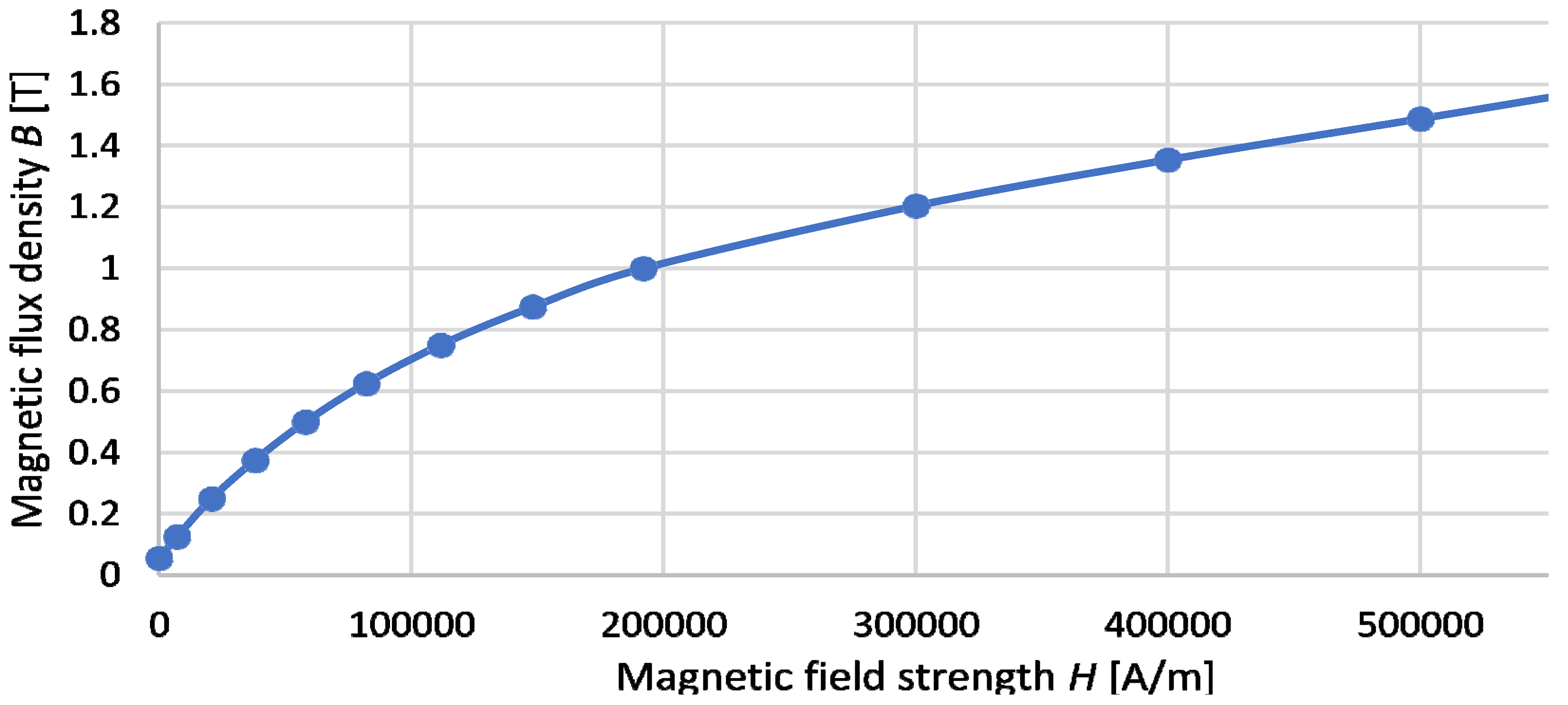
| B [T] | 0.055 | 0.125 | 0.25 | 0.375 | 0.5 | 0.625 | 0.75 | 0.875 | 1 | 1.21 | 1.35 | 1.49 | 1.62 |
| H [kA/m] | 0 | 7.1 | 20.8 | 38.1 | 58 | 82.1 | 111.5 | 148.2 | 191.9 | 300 | 400 | 500 | 600 |
| MR Fluid [mL] | Air [mL] | Void [mL] | |
|---|---|---|---|
| Variant 1 | 2.0 | 1.3 | 0 |
| Variant 2 | 2.0 | 0 | 1.3 |
| Variant 3 | 2.4 | 1.3 | 0 |
| Variant 4 | 2.4 | 0 | 1.3 |
Publisher’s Note: MDPI stays neutral with regard to jurisdictional claims in published maps and institutional affiliations. |
© 2021 by the authors. Licensee MDPI, Basel, Switzerland. This article is an open access article distributed under the terms and conditions of the Creative Commons Attribution (CC BY) license (https://creativecommons.org/licenses/by/4.0/).
Share and Cite
Białek, M.; Jędryczka, C.; Milecki, A. Investigation of Thermoplastic Polyurethane Finger Cushion with Magnetorheological Fluid for Soft-Rigid Gripper. Energies 2021, 14, 6541. https://doi.org/10.3390/en14206541
Białek M, Jędryczka C, Milecki A. Investigation of Thermoplastic Polyurethane Finger Cushion with Magnetorheological Fluid for Soft-Rigid Gripper. Energies. 2021; 14(20):6541. https://doi.org/10.3390/en14206541
Chicago/Turabian StyleBiałek, Marcin, Cezary Jędryczka, and Andrzej Milecki. 2021. "Investigation of Thermoplastic Polyurethane Finger Cushion with Magnetorheological Fluid for Soft-Rigid Gripper" Energies 14, no. 20: 6541. https://doi.org/10.3390/en14206541
APA StyleBiałek, M., Jędryczka, C., & Milecki, A. (2021). Investigation of Thermoplastic Polyurethane Finger Cushion with Magnetorheological Fluid for Soft-Rigid Gripper. Energies, 14(20), 6541. https://doi.org/10.3390/en14206541