Article

Analysis of Safety Requirements for Securing the Semi-Trailer Truck on the Intermodal Railway Wagon

Faculty of Transport, Warsaw University of Technology, Koszykowa 75, 00-662 Warsaw, Poland
Energies 2021, 14(20), 6539; https://doi.org/10.3390/en14206539
Submission received: 6 September 2021 / Revised: 7 October 2021 / Accepted: 9 October 2021 / Published: 12 October 2021
(This article belongs to the Collection Invited Papers on Electric Vehicles)

Abstract

:
The article presented the issue of securing semi-trailer trucks and trailers during their transport using intermodal railway wagons as a part of combined transport. This issue was analysed in different operational conditions related to loading level, cross-winds influence, inertia forces due to the emergency braking, and track curvature. According to general rules of loading and securing cargo, described in the internal and UIC regulations, the transported load should be positioned and secured with minimised risk of undesirable displacement or rolling over during transport. Basic analysis showed that adverse conditions such as strong winds or emergency braking may require adequate additional cargo protection. The lack thereof may result in a severe accident or damage to the transported vehicle or the nearby structures. The presented results for generic road and railway freight vehicles showed that the required anti-rollover torque for a semi-trailer mounted on the railway wagon platform may differ considerably (almost four times at the same maximum tested airflow speed) depending on the conditions related to aerodynamic and inertia influence. The potential weaknesses of the analysis relate to the impracticality of experimental tests for roll-over (or derailment) events under high levels of cross-wind, due to economic and safety reasons. The analysis can be extended in the future by including unsteady aerodynamic forces and a full-vehicle model based on the multi-body method for a specific design solution.

1. Introduction

Intermodal transport plays an increasingly important role in both the global and European freight transport markets. Its advantage is the pro-ecological form in relation to road transport and being part of a sustainable development plan. The plan consists of creating a competitive, resource-efficient transport system, namely to move 30% of goods transported over a distance of 300 km from the road to other types of transport by 2030 [1]. A similar commitment is implemented into the approved Transport Policy of several countries [2]. Among the most widespread and frequently transported intermodal transport units are large containers, swap bodies and, to some extent, semi-trailer trucks.
This type of cargo is usually transported on railroad wagon platforms equipped with standard ISO container pins or specialised lashing systems integrated into the wagon structure. Lashing with standard bolts and twist-locks is quite well analysed in the literature [3,4], while there is little information about specialised solutions. Some of the intermodal carriages systems found on the European market for the transport of semi-trailers or semi-trailer trucks include, e.g., Cargobeamer, Modalohr, Megaswing, Flexiwaggon, Sdggmrss/MAZ80800, WAT car, and others [5,6,7]. Safety reports show that dangerous incidents and accidents sometimes occur due to insufficient cargo securing on intermodal wagons [8]. An example is an accident in Denmark at the Great Belt in 2019 when a car trailer detached from a wagon and hit a passenger train, causing the death of eight people. At the same place, another incident happened the next year, under circumstances very similar to the previous circumstances (strong wind and empty trailer). A semi-trailer was pulled out of its position (up from the hitch) when crossing the low bridge on the Great Belt connection on the 13 January 2021 (Figure 1). During the investigations and tests performed after the incident, the Accident Investigation Board (AIB) found that the hitch lock in some of the tests carried out had no or limited locking effect when pulled vertically, even though the lock was in the correct locking position and the lock was well functioning, maintained, and lubricated as prescribed. The tests were performed on the incident hitch as well as several hitches of the same type. In the current European legislation, AIB has not been able to obtain information or identify any specific requirements for the function of a hitch in relation to the locking effect during vertical forces (unloading or during operation). In view of the tests and the apparent lack of requirements for locking effect in the vertical direction, it cannot be eliminated that a missing or limited locking effect due to vertical impact may occur with other types of hitches/locks in operation on the European railway network [8].
The combined transport volumes in EU have developed strongly over the past decade, and overall, the average annual growth rate from 2009 to 2019 exceeds 4.2%, including an average growth rate of 6.1% over the last two years (the majority of combined transport volume can be accounted for by unaccompanied services, while only a small amount is accompanied) [9]. Although the volume of freight traffic has increased, the railway mode of transport is generally safe, and the number of accidents is decreasing. According to ERA statistics, transporting goods by rail is, on average, 19 times safer than transporting those same goods by road. Increasing road safety is still a significant challenge, despite many undertaken actions [10]. On the other hand, the accidents mentioned before seem to be a good reason to look at the requirements for securing cargo in combined transport under the conditions of increased aerodynamic and inertial impact. Such conditions and the associated scope of application of load securing are not described in detail in the current regulations, particularly regarding aerodynamic effects.
Another reason relates to the attempts to create innovative wagons for combined rail-road transport using semi-trailers and semi-trailer trucks [6,7,11]. These wagons are intended to facilitate the loading and unloading of road vehicles by not requiring additional external loading equipment.

2. Analysis of Cargo Securing Requirements

In this paragraph, the analysis of cargo securing requirements is based on the general guidelines provided by the UIC standards [12,13,14,15,16,17]. As a general rule, transport safety must not be compromised as a result of cargo displacement and weather conditions influence such as wind, snow, icing of the loading surface, and the cargo itself. We can also list some of the rules generally accepted by the rail carriers applicable when loading and transporting semi-trailers and semi-trailer trucks by rail wagons [14,15,16,17]:
  • Only a road vehicle which condition meets the requirements of the Road Transport Regulation may be approved for loading, e.g., in terms of dimensions, total weight, and permissible axial loads.
  • Ensure that the tarpaulin mounts are correctly closed, the side mirrors are folded in, and the outer equipment is correctly fitted or secured (spoilers, snow chains, ladders, bridges, handrails, tank covers, closing flaps, buckets, shovels, etc.).
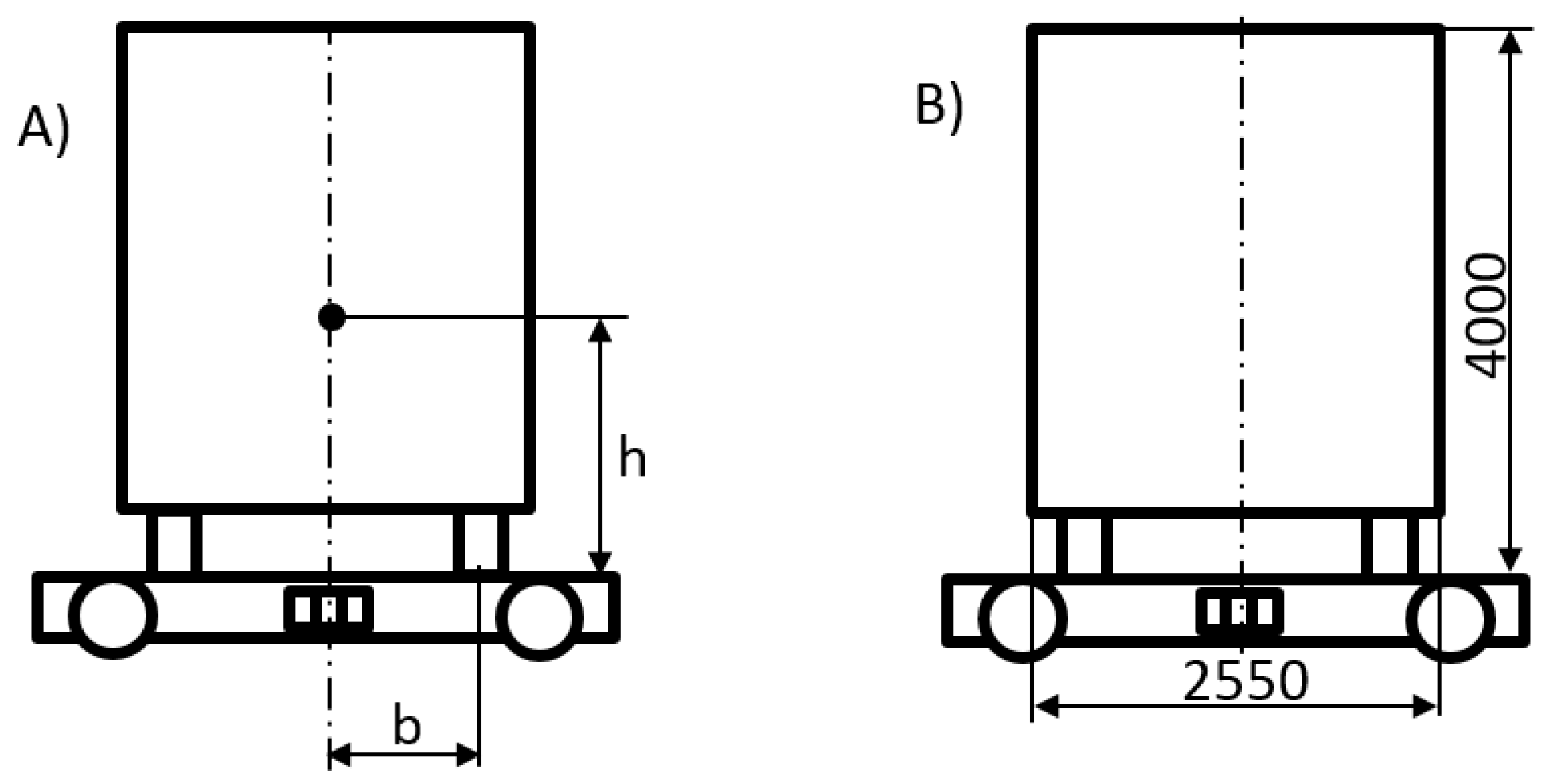
  • Radio antennas must be fully retracted or removed if the truck’s height exceeds 4 m. Radio receiving and transmitting devices (including alarm systems) must be turned off to prevent automatic height changes of the antennas.
  • After loading, gear must be engaged, the parking or hydraulic brake applied, and the engine turned off, which will remain off while the train is running.
  • Secure the car with wheel wedges and, if necessary, depressurize the air suspension and lock the door.
The load must rest in a stable position, secured against displacement relative to the wagon in every possible direction, without causing damage to the wagon itself or causing significant differences in a load of individual wheels.
The required uniformity of load distribution can be assessed from the ratio of the wagon wheel pressure on the rails in the longitudinal and transverse directions while maintaining the permissible axle load [12,13]. The maximum ratio of wheel pressures on one axle must not exceed the value of 1.25:1. However, in the longitudinal direction, the maximum pressure ratio must not exceed:
2:1—in relation to the front and rear axle load on a wagon without bogies,
3:1—regarding the centre pivot of the front and rear bogie frame E1 and E2 in a wagon equipped with bogies (Figure 2).
Car wheel pressures cannot cause deformation of the wagon platform. To determine the values of the respective pressures, the following equations describing the interaction between the semi-trailer truck and the wagon platform can be used. For simplicity’s sake, it was assumed that the three rear axles of the trailer have similar normal reactions on each axle and the total resultant reaction is denoted N3.
Truck:
Z :   N 1 P C Z + N 2 N 4 = 0 Y : T 1 T 2 + P C Y + T 4 = 0 X :   N 4 L 3 + P C Z L 1 N 2 ( L 1 + L 2 ) P C Y h 1 T 4 h 3 = 0
Semi-trailer:
Z : N 4 + N 3 P N Z = 0 Y : T 4 T 3 + P N Y = 0 X : P N Z L 5 N 3 L 4 T 3 h 3 P N Y ( h 2 h 3 ) = 0
T 1 N 1 = T 2 N 2 = T 3 N 3 ;   a g = r ;   r m a x k
N 3 = P N Z ( L 5 r ( h 2 h 3 ) ) / ( L 4 + r h 3 ) ; N 4 = P N Z ( 1 ( L 5 r ( h 2 h 3 ) ) / ( L 4 + r h 3 ) ) ; N 2 = ( N 4 L 3 + P C Z L 1 P C Z r h 1 ( P N Z N 3 ) r h 3 ) / ( L 1 + L 2 ) ; N 1 = P C Z + N 4 N 2 ;
where: a—braking deceleration, g—gravitational acceleration, k—theoretical wheel-platform adhesion coefficient, N,T—normal and tangential forces, P—inertia forces.
The following data were used for calculations.
Geometric quantities [m]: L1 = 2.03; L2 = 1.78; L3 = 3.4; L4 = 7.7; L5 = 5.75; h1 = 0.97; h2 = 1.8; h3 = 1.07.
Total mass: tractor mc = 8 t, loaded semi-trailer mz = 30 t, empty semi-trailer = 8 t.
Average emergency braking deceleration a = 1.5 m/s2 [19].
The results are given in Table 1 and Table 2.
The pressure distribution on the investigated platform is relatively even; the ratio of static forces E2/E1 is 1.4 when the car is fully loaded. The axial load of one wheelset on the front bogie is 129 kN and the rear one 175 kN.
Based on the assumed sliding friction coefficient (source: DEKRA), it is possible to assess the possibility of slipping of the vehicle tires from the metal platform of the wagon. The range of values of this coefficient in relation to the surface condition (in rubber-steel contact): clean/dry 0.4–0.45; contaminated/dry 0.3; contaminated/wet 0.1–0.2. During the emergency braking of the wagon, according to the adopted deceleration value, the minimum value of the contact friction coefficient at which the friction force prevents the wheels from slipping is on average kmin = a/g; kmin = 0.153; thus, with the wet and contaminated surface of the wagon platform, there is a danger of wheels slipping during braking if the wheels are not properly supported.
During transportation, the forces act on certain structural elements of the vehicles through fasteners. The load is transferred to hooks, hinges, axles, chassis, technological holes, and other fastening parts. If the wagon is not equipped with another special type of protection, then the standard protection against displacement of the car’s wheels is implemented using wedges placed under each wheel. Examples of wedge placement are shown in Figure 3. The material and dimensions of the wedges depend on the weight of the car. For weights up to 6 t, wooden or plastic wedges can be used with a height equal to 1/8 of the diameter of the wheel, a minimum of 12 cm. At a weight of more than 6 tons, steel wedges with a minimum height of 17 cm are recommended, equipped with spikes or bolts that allow attachment to the wagon floor. The wedge angle should be 35–45 degrees. The number of bolts securing the wedge to the platform depends on the vehicle’s weight; these bolts must transfer forces resulting from the difference between the horizontal force with which the wheels act on the wedge and the friction force resulting from the available wedge-platform adhesion. The average value of this force is:
T S = ( m c + m z ) ( a μ g ) j   w h e n   ( a μ g ) > 0
where j—number of wheels, μ —friction coefficient, a—acceleration. If it is not possible to use locking wedges, they can be replaced with belts of adequate strength. In addition, any moving parts of the car should be immobilised with a belt with a strength of 10–40 kN.
Theoretical calculations show that the structural elements of the platform carry significant loads proportional to the vehicle mass. The wheels of the semi-trailer generate the highest load.
Another requirement concerns the roll-over protection. The higher the centre of gravity of the semi-trailer truck, the more likely it is to tip over due to horizontal forces. The likelihood of rolling over the road vehicle in the longitudinal direction is negligible due to the considerable length of the vehicle. In contrast, for the transverse direction, the assessment criterion is based on the condition of equilibrium of moments derived from the weight of the vehicle and the transverse force applied to the centre of mass, being the result of inertia and external forces. These moments apply to the longitudinal axis of rotation passing through the contact points between the wheels and the platform at one side of the vehicle. Simplifying the moments’ equation, we compared the height of the vehicle’s centre of mass h and the length of half-track width b (Figure 4, Equation (6)), which is also described as Static Stability Factor (SSF).
b h ( b h ) m i n
Additional rollover protection is required if the b/h value is less than 0.5 or 0.7 for flat and low bed wagons if the ratio of the weight of the load unit to the exposed side surface exposed to the wind (product of the length and height of the loaded container) is smaller than 1 t/m2 [12]. The length of a typical semi-trailer in a 40 t road vehicle is 13.6 m, and the height of 3 m gives 40.8 m2 of the side surface (not including the cabin and chassis). Since the permissible total weight of the set is 40 t, the ratio of the load weight to the side surface of a typical road set may be smaller or close to 1 t/m2, which, according to the cited criterion, indicates susceptibility to side wind and an increased risk of tipping over the road vehicle in adverse conditions.
The track width is limited by the maximum permissible vehicle width of 2.55 m [20,21]; usually, it is close to 2 m, while the height of the centre of mass depends on the loading conditions of the road vehicle’s semi-trailer. Figure 5 shows the limit values at which the ratio of half-track width to the height of the centre of mass meets the safety condition.
Assuming unfavourable conditions associated with underload of the road vehicle with intense side wind and assuming a value of half-track width of 1 m, the maximum safe height of the centre of mass of the road vehicle according to the criterion is 1.43 m, i.e., relatively low height compared to the total height of the vehicle. This result seems to suggest the need for a more detailed investigation of the lateral overturning possibility.
Research conducted in the last decade suggests that there is a clear risk of the road train tipping over or slipping as a result of strong winds, especially in such exposed places as embankments, viaducts, and bridges, as well as near places where there are rapid changes in aerodynamic forces due to wind acceleration, e.g., at the pylons of bridges. Based on the cited literature, we can summarise selected conclusions from the research on aerodynamic effects on the vehicle from the point of view of this article:
  • Critical wind velocities of overturning vary with natural wind directions and train speeds. For a fixed cross-wind speed, the rollover moment increases with vehicle speed. A critical wind speed is the gust speed (a few second gust) with a certain annual probability of exceedance [22,23,24,25,26,27].
  • The instantaneous wind velocities exceeding 20–25 m/s are considered high risk for train operation, especially in exposed places such as bridges and embankments. The critical cross-wind speed for road vehicles may be lower [24,28,29,30,31].
  • Several strategies can be used to successfully reduce the vehicle overturning moment in cross-wind successfully. Changing the shape of the trailer can mitigate the overturning risk (e.g., it is possible to reduce the overturning moment by 25% with a rounded corner [32]). Other schemes include meteorological warnings (roadside anemometry or the local weather station), vehicle restrictions, and roadside wind barriers [32,33,34,35].

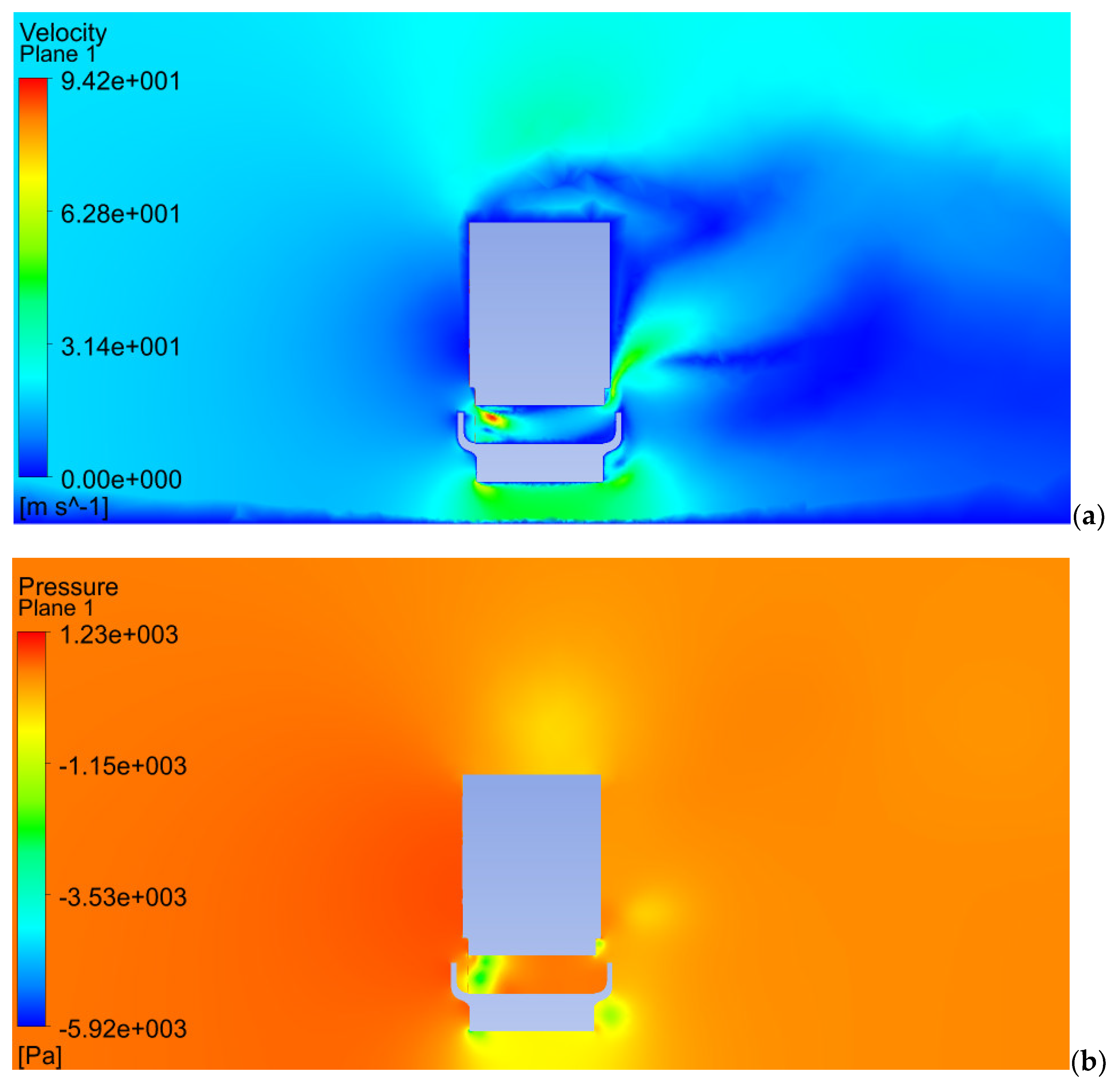
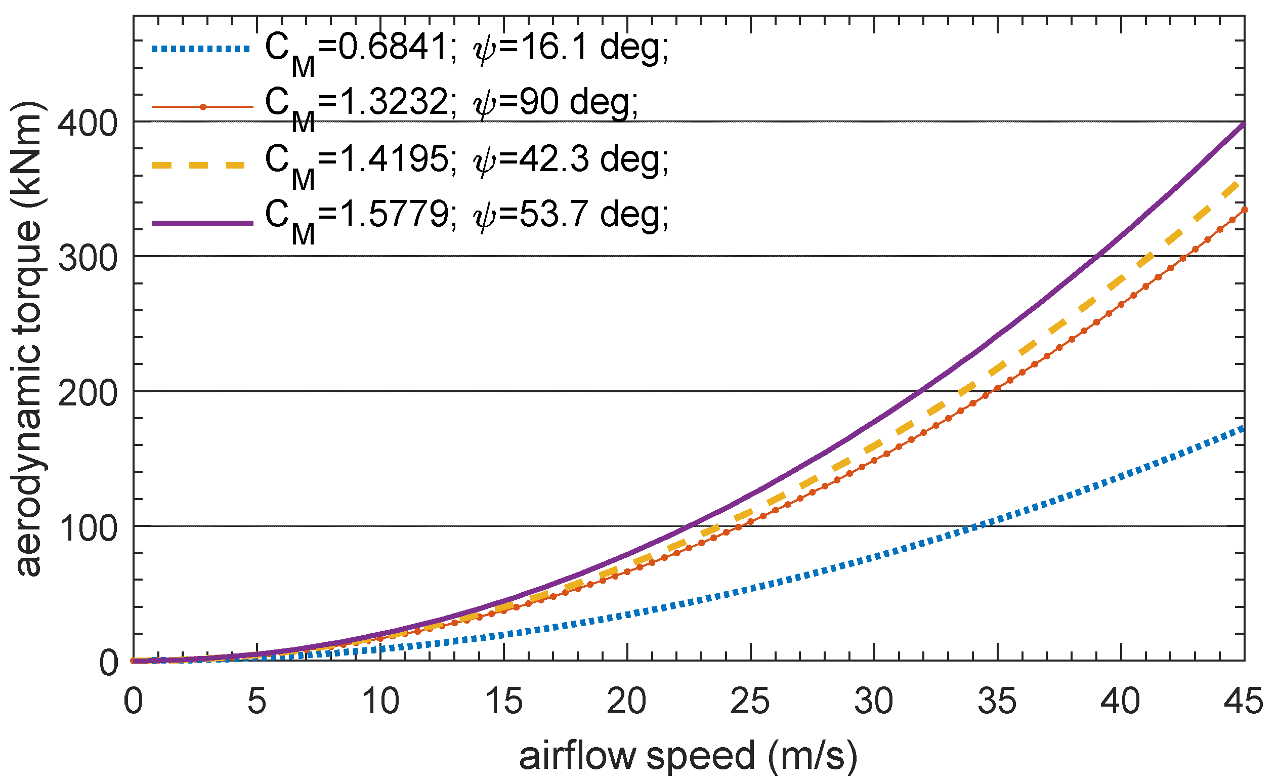
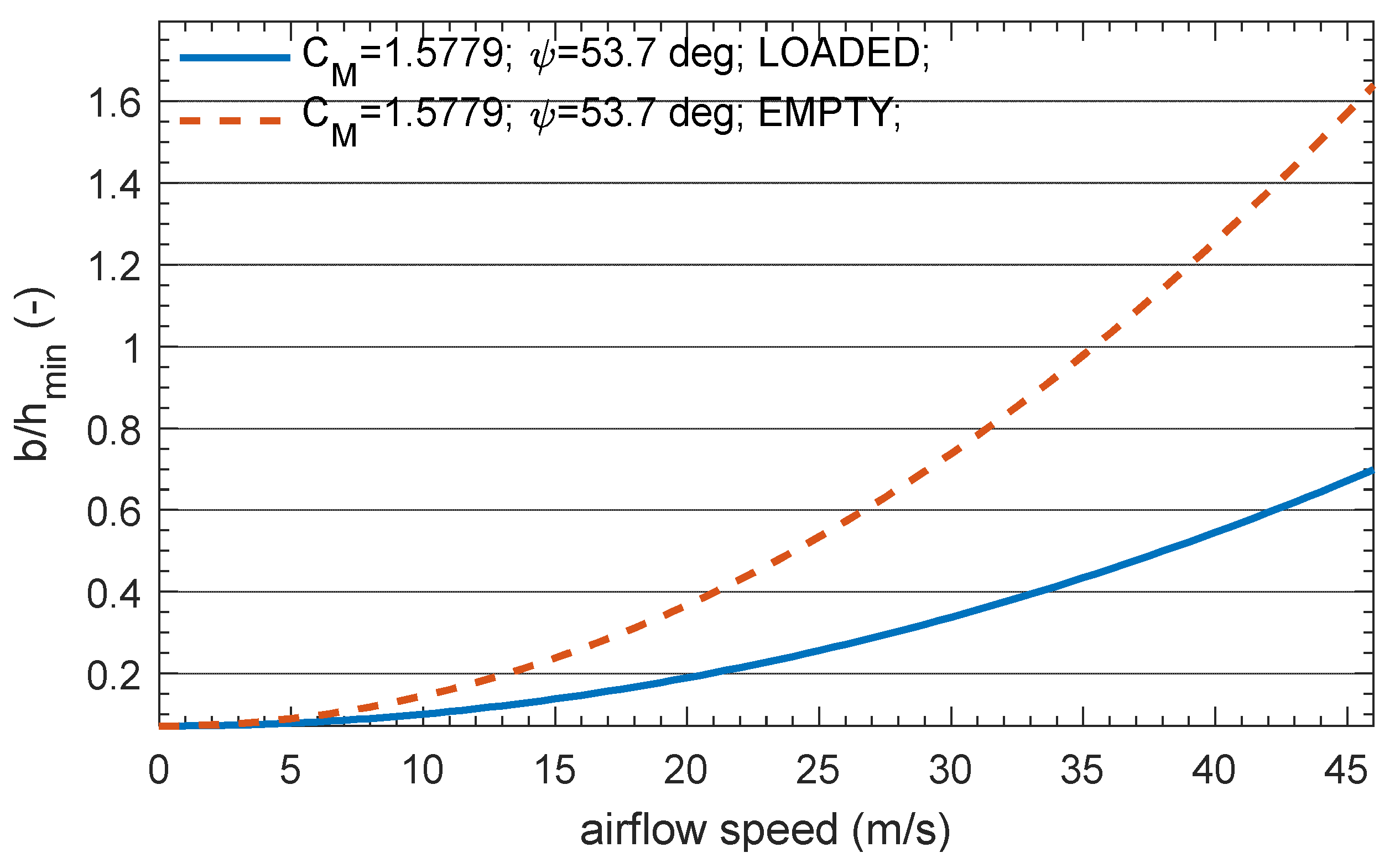
3. Analysis of Aerodynamic and Inertia Effects

Apart from the rail vehicle stability and derailment criteria due to cross-winds (EN14067-6 and TSI RST) related to the wheel unloading, the existing standardised criteria for assessing the risk of the cargo detachment during transport on the railway flat-car contain mostly the geometric parameters of the mass centre location and the spacing of the support points, but do not allow for the assessment of what loads should be transferred by the fastenings given the influence of the strong wind. Generally, we can use three methods for estimating both steady and transient aerodynamic characteristics of ground vehicles: full-scale measurements, scale model experiments, and computational fluid dynamic (CFD) simulations. Experimental tests, including roll-over (or derailment) events under high levels of cross-wind, are not practicable due to economic and safety reasons. Given this perspective, numerical methods provide a general tool applicable to different wind conditions. In order to determine the forces transferred at the anchorages or the coefficients of aerodynamic drag and cross-wind effects on the road vehicle mounted on the railway platform, a 3D numerical analysis was carried out using a commercial CFD package.
In the quasi-steady analysis of the aerodynamic forces acting on the vehicle, the resultant external aerodynamic force is defined as:
F ¯ = [ F D , F S , F L ] ,
where F D —drag, F S —side force, F L —lift force, and the corresponding stationary aerodynamic roll moment about the leeward contact axis between the road vehicle and the wagon platform is defined as:
M A = 1 2 ρ A H C M v r 2 ,
where: C M —aerodynamic coefficient, ρ —air density, v r —airflow relative to the vehicle (Figure 6, Equation (13)), H – reference height, A —reference area.
The relative air velocity can be described using different conventions; in the following description, the moving reference frame is connected to the vehicle, which travels with a constant velocity v ¯ u measured in the fixed frame. Relative airflow velocity v ¯ r is measured in the moving frame, while natural wind velocity v ¯ c is measured in the fixed frame.
Vehicle velocity in the fixed frame xyz (velocity of the moving frame attached to the vehicle):
v ¯ u = [ v u , 0 , 0 ] ,
Cross-wind velocity in the fixed frame:
v ¯ c = [ v c s i n β , v c c o s β , 0 ] ,
where β —natural cross-wind direction measured from the lateral axis, perpendicular to the vehicle velocity, v c —absolute natural cross-wind speed.
Airflow velocity relative to the vehicle, calculated in the fixed frame:
v ¯ r = v ¯ c v ¯ u ,
v ¯ r = [ v c s i n β v u , v c c o s β , 0 ] ,  
v r = ( v c s i n β v u ) 2 + ( v c c o s β ) 2 ,
Yaw angle of the relative airflow velocity in the fixed frame:
ψ = a r c s i n v c c o s β v r
Airflow velocity relative to the vehicle, calculated in the moving frame x’y’z’, which is rotated about the longitudinal x axis due to the railway cant:
v ¯ r m = R x · v ¯ r ,
where R is rotation matrix
R x = [ 1 0 0 0 c o s α s i n α 0 s i n α c o s α ] ,
v ¯ r m = [ v c s i n β v u , v c c o s β c o s α , v c c o s β s i n α ] ,   | v ¯ r m | = | v ¯ r |
According to the Figure 6 the quasi-static equation of equilibrium of the transported road vehicle rolling motion is:
( G s i n α F B c o s α ) h G b c o s α + N I 2 b + M A = 0 ,  
where M A —rolling torque due to aerodynamic forces, F B —centrifugal force, h —height of the vehicle’s centre of mass, b —half-track width, G —weight, N I —inner wheel normal reaction force.
The inner normal force N I can be any value from zero to G/2; it does not participate in rotation about the outer tire, because it reaches zero before the tipping point.
Assuming the maximum allowed unbalanced lateral acceleration a f , the minimum torque M R   required to prevent the road vehicle from overturning initiation is:
M R = G g a f h G b c o s α + M A
In order to calculate the aerodynamic load M A , the CFD mesh model was prepared, consisting of 866,037 nodes and 4,819,836 elements; the mesh bounding box measures 45 × 55 × 15 m. The model of the test vehicle is constructed for a more accurate representation of the generic shape and a less detailed representation of the bogies, inter-car gaps, and train exterior surface features. The basic shape of the intermodal wagon and semi-trailer truck body is modelled in width and height to a tolerance of ± 0.02 m full scale from the actual shape (Figure 7).
For this analysis, a pressure based steady-state solver was used. The solution methods, equations used, and the input data include a realisable k-epsilon model with non-equilibrium wall functions; input data include relative airflow velocity in the range 0–33 m/s2 (described by Equations (7)–(16)) due to the train’s forward motion and cross-wind directed at different angles. In order to test the accuracy of the results obtained by employing the solver settings, several test simulations were carried out for the Ahmed body (comparing the drag coefficient obtained from the CFD simulation with the wind tunnel result for a certain body geometry). The particular goal of this benchmark was to compare the total drag coefficient for different volumes and refinement levels of the mesh model; element size was refined until the result did not change significantly. The mesh metrics were also adjusted according to skewness and orthogonal quality variables. While comparing the numerical and experimental results of the drag coefficient, the aim was to obtain an error value below 6%.
Additional inputs included unbalanced lateral acceleration due to the track curvature and cant (Equations (17) and (18)), while the maximum unbalanced lateral acceleration value was assumed as 0.7 m/s2 based on the railway standards. The analysis in this part focuses on calculating external forces and torques acting on the stiff cargo structure; the interactions are subsequently transferred to the locking mechanisms between the cargo and the wagon platform. The direct influence on the railway vehicle in terms of stability and derailment safety was not taken into account. Figure 8 shows an example of velocity and pressure maps in the vertical plane perpendicular to the longitudinal vehicle axis. The upper part of the vehicle system is the semi-trailer cross-section at the area between the vehicle wheels.
Selected results of aerodynamic forces, torques, and coefficients calculated in the CFD simulations in reference to the relative airflow velocity components are presented in Table 3. Relative airflow components are given in the fixed reference frame, and reaction torque M R is calculated according to Equation (18) for two cases: transported semi-trailer empty and fully loaded (b = 1 m, h = 1.7 m).
It is worth noting that calculated aerodynamic side force F S in the lateral direction is relatively high in comparison with the forces in longitudinal direction (Table 2). Using the coefficients obtained from the CFD simulations, Figure 9 demonstrates the aerodynamic overturning moment acting on the truck and trailer standing on the railway wagon running in the environment of different wind velocities.
For comparison purposes, we can derive the (b/h)min ratio (Equation (17)) taking into account the unbalanced lateral acceleration and calculated aerodynamic load, which is demonstrated in Figure 10. It tells us what must be the minimum b/h ratio for a given airflow speed to prevent the road vehicle from overturning initiation without additional roll-over protection. Consequently, the (b/h)min ratio is valid for the certain ranges of vehicle and wind speeds. Based on the UIC loading guidelines and the present study, (b/h)min ratio equal to 0.5 is valid up to 24 m/s airflow speed for empty road vehicle and up to 38 m/s when fully loaded. Higher (b/h)min limit equal to 0.7 is valid up to 29 m/s airflow speed for empty and up to 46 m/s for fully loaded road vehicle. It can be observed that an empty vehicle is definitely more likely to tip over without additional roll-over protection. An example of calculated roll-over protection torques is given in Figure 11 for particular values of geometric parameters describing the height of the vehicle’s mass centre h and half-track width b. Calculated reaction torque and lift force can be readily used for determining the vertical forces needed at the locking points of the cargo.

4. Discussion

The article discussed the selected safety measures related to the transport of semi-trailer trucks and trailers using an intermodal railway wagon from the point of view of securing a road vehicle to the wagon platform. Based on the mathematical models, selected values of quasi-static interactions between the road vehicle and the wagon platform were determined for specific conditions and safety criteria were given. These criteria can be used to develop and verify technologies for transporting semi-trailer trucks by railway. The presented results showed that an empty semi-trailer under the strong influence of aerodynamic forces requires almost four times (380%) more anti-rollover torque than a fully loaded semi-trailer at the same maximum tested airflow speed. It can be observed that for aerodynamic effects at the maximum airflow speed, the influence of the height of the mass centre of the loaded semi-trailer is medium (30%) and for the empty vehicle is small (3%), assuming differences in the height of the mass centre between 1.7 and 2.5 m. This is because the position of the centre of pressure is almost invariant under different airflow fluctuations and the inertia effects related to the lateral acceleration in the assumed range are less evident in comparison to the aerodynamic effects.
The restoring moment due to the semi-trailer’s weight depends mainly on the half-track width of the car (length of the moment arm). Increasing the semi-trailer’s weight will increase the restoring moment at the cost of higher axle load and energy consumption during road travel. More weight is also less beneficial due to the higher centrifugal forces while driving a truck around curves. The radii of curvature of road curves are usually smaller than the curvature radii of railroad tracks. A reduction of the vehicle height would reduce the aerodynamic roll moment and side force but is not feasible. Keeping the centre of gravity as low as possible will benefit cross-wind stability; however, it might not be enough to prevent lateral roll-over in adverse strong wind conditions and unloaded semi-trailer.
The cargo and wagon platform interactions depend on the method used to secure the wheels and the kingpin to the platform. The main structural elements potentially affected by interaction forces due to the combination of static and dynamic loads are the wagon platform in the area of the trailer wheel support and the road vehicle chassis components to which the mountings are attached. Innovative concepts for rail wagons for combined transport often assume that the platform onto which the vehicle drives itself is movable to make loading independent of external loading facilities, this places additional strength requirements on the platform elements. Knowing the external forces and torques for various conditions, we can design appropriate means for safely loading and fixing the cargo. For a specific design solution, the analysis can be extended by including unsteady aerodynamic forces and a full-vehicle model based on the multi-body method.

Funding

This research was funded by the Warsaw University of Technology within the IDUB-Open Science Program.

Institutional Review Board Statement

Not applicable.

Informed Consent Statement

Not applicable.

Conflicts of Interest

The author declares no conflict of interest. The funders had no role in the design of the study; in the collection, analysis, or interpretation of the data; in the writing of the manuscript; or in the decision to publish the results.

References

  1. The European Commission. European Strategies, the White Paper. Available online: https://ec.europa.eu/transport/themes/strategies/2011_white_paper_en (accessed on 11 October 2021).
  2. Cempírek, V.; Vrbová, P.; Zákorová, E. The Possibility of Transferring the Transport Performance on Railway Transport. MATEC Web Conf. 2017, 134, 00006. [Google Scholar] [CrossRef]
  3. DNV GL AS, Container securing, DNVGL-CG-0060. 2016. Available online: https://rules.dnv.com/docs/pdf/DNV/CG/2016-02/DNVGL-CG-0060.pdf (accessed on 11 October 2021).
  4. Lew, H.S.; Sadek, F.; Anderson, E.D. Strength Evaluation of Connectors for Intermodal Containers; NISTIR 6557; NIST, United States Department of Commerce, Technology Administration: Washington, DC, USA, 2000. [Google Scholar]
  5. Krasoń, W.; Niezgoda, T.; Stankiewicz, M. Innovative Project of Prototype Railway Wagon and Intermodal Transport System. Transp. Res. Procedia 2016, 14, 615–624. [Google Scholar] [CrossRef] [Green Version]
  6. Nader, M.; Sala, M.; Korzeb, J.; Kostrzewski, A. Kolejowy wagon transportowy jako nowatorskie, innowacyjne rozwiązanie konstrukcyjne do przewozu naczep siodłowych i zestawów drogowych dla transportu intermodalnego (Railroad transport wagon as a novel, innovative construction solution for transporting semi-trailers and road sets for intermodal transport). Logistyka 2014, 4, 2272–2279. [Google Scholar]
  7. Nader, M.; Opala, M.; Korzeb, J. Wybrane zagadnienia badania dynamiki wagonu typu platforma do przewozu zestawów drogowych (Selected issues of testing the dynamics of a platform wagon for carrying road sets). Pr. Nauk. Politech. Warsz. Transp. 2019, 125, 101–111. [Google Scholar]
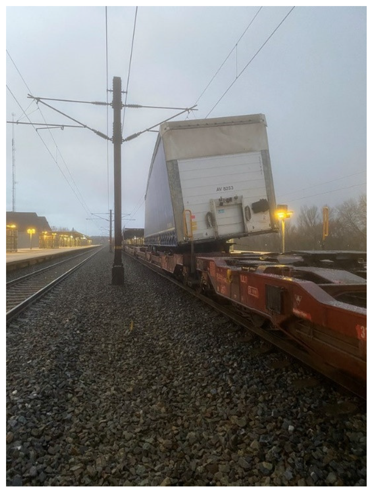
  8. Accident Investigation Board (AIB Denmark), Safety Alert. January 2021. Available online: https://en.havarikommissionen.dk/media/12715/j_2021_haendelse_2021-24_andet_storebaelt_safety-alert.pdf (accessed on 11 October 2021).
  9. UIC Freight Department, Report on Combined Transport in Europe. November 2020. Available online: https://uic.org/IMG/pdf/2020_combined_transport_report_press_conference_202010230.pdf (accessed on 11 October 2021).
  10. Mikusova, M.; Gnap, J. Experiences with the implementation of measures and tools for road safety improvement. In Proceedings of the CIT2016—XII Congreso de Ingeniería del Transporte, València, Spain, 7–9 June 2016; Universitat Politècnica de València: València, Spain, 2016. [Google Scholar] [CrossRef] [Green Version]
  11. Nader, M.; Sala, M. Rail Transport Wagon, Rail Transport Unit and Rail Transport System Incorporating Such a Wagon, Invention. Patent/right number: PL 214797; Application date (in the first country of application): 14 December 2009, Grant date: 17 December 2012,
  12. UIC. Loading Guidelines Code of Practice for the Loading and Securing of Goods on Railway Wagons, Volume 1, Principles, 3rd ed. 2019. Available online: https://uic.org/freight/wagon-issues/loading-rules (accessed on 11 October 2021).
  13. UIC. Loading Guidelines Code of Practice for the Loading and Securing of Goods on Railway Wagons, Volume 2, Goods, 3rd ed. 2019. Available online: https://uic.org/freight/wagon-issues/loading-rules (accessed on 11 October 2021).
  14. UIC 571-4 Standard wagons—Wagons for combined transport—Characteristics. 2011.
  15. UIC 596-6 Transport of road vehicles on wagons—Technical Organisation—Conveyance of semi-trailers with P coding or N coding on recess wagons. 2008.
  16. Rail Cargo Group/ROLA, Loading Instructions. 2021. Available online: https://rola.railcargo.com (accessed on 11 October 2021).
  17. Ralpin, General Conditions of Carriage. 2021. Available online: https://ralpin.com (accessed on 11 October 2021).
  18. Day, A. Breaking of Road Vehicle, 1st ed.; Elsevier: Amsterdam, The Netherlands, 2014; ISBN 978-0-12-397314-6. [Google Scholar]
  19. PN-EN 13452-1:2003—Kolejnictwo—Hamowanie—Systemy hamowania w transporcie publicznym—Część 1: Wymagania eksploatacyjne (Railroad applications—Braking—Braking systems in public transport—Part 1: Performance requirements).
  20. Obwieszczenie Ministra Infrastruktury i Budownictwa z dnia 27 Października 2016 r. W Sprawie Ogłoszenia Jednolitego Tekstu Rozporządzenia Ministra Infrastruktury w Sprawie Warunków Technicznych Pojazdów oraz Zakresu ich Niezbędnego Wyposażenia (Announcement by the Minister on the Consolidated Text of the Regulation of the Minister of Infrastructure on Technical Conditions of Vehicles and the Scope of Their Necessary Equipment). 2016. Available online: http://isap.sejm.gov.pl/isap.nsf/DocDetails.xsp?id=WDU20160002022 (accessed on 11 October 2021).
  21. Rozporządzenie Ministra Infrastruktury z dnia 24 Grudnia 2019 r. Zmieniające Rozporządzenie w Sprawie Warunków Technicznych Pojazdów oraz Zakresu ich Niezbędnego Wyposażenia (Regulation of the Minister of Infrastructure on Technical Conditions of Vehicles and the Scope of Their Necessary Equipment). 2019. Available online: http://isap.sejm.gov.pl/isap.nsf/DocDetails.xsp?id=WDU20190002560 (accessed on 11 October 2021).
  22. Cheli, F.; Corradi, R.; Tomasini, G. Crosswind action on rail vehicles: A methodology for the estimation of the characteristic wind curves. J. Wind Eng. Ind. Aerodyn. 2012, 104–106, 248–255. [Google Scholar] [CrossRef]
  23. Bettle, J.; Holloway, A.G.L.; Venart, J.E.S. A computational study of the aerodynamic forces acting on a tractor-trailer vehicle on a bridge in cross-wind. J. Wind Eng. Ind. Aerodyn. 2003, 91, 573–592. [Google Scholar] [CrossRef]
  24. Fujii, T.; Maeda, T.; Ishida, H.; Imai, T.; Tanemoto, K.; Suzuki, M. Wind-Induced Accidents of Train/Vehicles and Their Measures in Japan. Q. Rep. RTRI 1999, 40, 50–55. [Google Scholar] [CrossRef] [Green Version]
  25. Proppe, C.; Wetzel, C. Overturning Probability of Railway Vehicles under Wind Gust Loads. In Iutam Symposium on Dynamics and Control of Nonlinear Systems with Uncertainty; Hu, H.Y., Kreuzer, E., Eds.; IUTAM Book Series; Springer: Dordrecht, The Netherlands, 2007; Volume 2. [Google Scholar] [CrossRef]
  26. Li, A.; Xiong, X. Research on the Influence of Strong Crosswind on Aerodynamic Characteristics and Operation Safety of EMUs. In DEStech Transactions on Engineering and Technology Research; 2017; pp. 443–451. ISBN 978-1-60595-481-3. [Google Scholar] [CrossRef] [Green Version]
  27. Baker, C.; Johnson, T.; Flynn, D.; Hemida, H.; Quinn, A.; Soper, D.; Sterling, M. Train Aerodynamics; Butterworth-Heinemann: Oxford, UK, 2019; ISBN 978-0-12-813310-1. [Google Scholar]
  28. Baker, C.; Cheli, F.; Orellano, A.; Paradot, N.; Proppe, C.; Rocchi, D. Cross-wind effects on road and rail vehicles. Veh. Syst. Dyn. 2009, 47, 983–1022. [Google Scholar] [CrossRef]
  29. Charuvisit, S.; Kimurab, K.; Fujinoc, Y. Experimental and semi-analytical studies on the aerodynamic forces acting on a vehicle passing through the wake of a bridge tower in cross wind. J. Wind Eng. Ind. Aerodyn. 2004, 92, 749–780. [Google Scholar] [CrossRef]
  30. Diedrichs, B.; Sima, M.; Orellano, A.; Tengstrand, H. Crosswind stability of a high-speed train on a high embankment. Proc. Inst. Mech. Eng. Part F-J. Rail Rapid Transit 2007, 221, 205–225. [Google Scholar] [CrossRef]
  31. Abdulwahab, A.; Mishra, R. Estimation of LTR rollover index for a high-sided tractor semitrailer vehicle under extreme crosswind conditions through dynamic simulation. In Proceedings of the 2017 23rd International Conference on Automation and Computing (ICAC), Huddersfield, UK, 7–8 September 2017. [Google Scholar] [CrossRef]
  32. Salati, L.; Schito, P.; Cheli, F. Strategies to reduce the risk of side wind induced accident on heavy truck. J. Fluids Struct. 2019, 88, 331–351. [Google Scholar] [CrossRef]
  33. Chen, N.; Li, Y.; Wang, B.; Su, Y.; Xiang, H. Effects of wind barrier on the safety of vehicles driven on bridges. J. Wind Eng. Ind. Aerodyn. 2015, 143, 113–127. [Google Scholar] [CrossRef]
  34. Deng, E.; Yang, W.; He, X.; Zhu, Z.; Wang, H.; Wang, Y.; Wang, A.; Zhou, L. Aerodynamic response of high-speed trains under crosswind in a bridge-tunnel section with or without a wind barrier. J. Wind Eng. Ind. Aerodyn. 2021, 210, 104502. [Google Scholar] [CrossRef]
  35. Guo, X.; Tang, J. Effects of Wind Barrier Porosity on the Coupled Vibration of a Train-Bridge System in a Crosswind. Struct. Eng. Int. 2019, 29, 268–275. [Google Scholar] [CrossRef]
Figure 1. In 2021 during the passage of a freight train over the bridge, the semi-trailer was forced out of its attachment (strong wind and empty trailer), source: utk.gov.pl (accessed on 11 October 2021) [8].
Energies 14 06539 g001
Figure 2. Road vehicle interactions with the wagon platform, based on [18], Ni,Ti—normal and tangential forces, Pi—inertia forces, Ei—vertical force at the railway bogie centre pivot.
Energies 14 06539 g002
Figure 3. Examples of the arrangement of wedges under the wheels of a road vehicle [13].
Energies 14 06539 g003
Figure 4. (A) Position of the mass centre and half-track width, (B) maximum dimensions; b—half-track width, h—height of the mass centre.
Energies 14 06539 g004
Figure 5. Relationships between half-track width b and height of the centre of mass h, meeting the safety condition.
Energies 14 06539 g005
Figure 6. Relative airflow velocity v ¯ r and aerodynamic forces.
Energies 14 06539 g006
Figure 7. CFD model of railway wagon with semi-trailer truck, (a) internal geometry model, (b) mesh model, (c) model volume and airflow direction.
Energies 14 06539 g007aEnergies 14 06539 g007b
Figure 8. (a) Velocity map for the cross-wind speed 20 m/s, visible in the middle plane between the platform bogies, (b) pressure map for the cross-wind speed 20 m/s.
Energies 14 06539 g008
Figure 9. Overturning torque due to the aerodynamic effects vs. airflow speed, C M —aerodynamic coefficient, ψ —yaw angle of the relative airflow velocity.
Energies 14 06539 g009
Figure 10. Relationships between half-track width b and height of the mass centre h, meeting the safety condition (Equation (6)) vs. airflow speed, C M —aerodynamic coefficient, ψ —yaw angle of the relative airflow velocity.
Energies 14 06539 g010
Figure 11. Reaction moment of the cargo-platform locking device in reference to the longitudinal vehicle axis assuming constant b = 1 m, b/h = 0,59 for h = 1.7 m, and b/h = 0.4 for h = 2.5 m, C M —aerodynamic coefficient, ψ —yaw angle of the relative airflow velocity.
Energies 14 06539 g011
Table 1. Normal forces between the road vehicle and the railway wagon platform for the static loading case and during emergency braking.
Loading CaseN1
[kN]
N2
[kN]
N3
[kN]
N4
[kN]
N1 + N2 + N3
[kN]
Empty38.859.658.619.9157
Loaded44.6108.3219.874.5372.7
Values during emergency braking of the train (a = 1.5 m/s2)N1
[kN]
N2
[kN]
N3
[kN]
N4
[kN]
N1 + N2 + N3
[kN]
Empty43.257.656.222.2157
Loaded52.2109.521183.3372.7
Table 2. Tangential forces between the road vehicle and the railway wagon platform during emergency braking of the train (a = 1.5 m/s2).
LoadT1
[kN]
T2
[kN]
T3
[kN]
T4
[kN]
T1 + T2 + T3
[kN]
Empty6.68.88.63.424
Loaded816.732.312.757
Table 3. Selected results of aerodynamic forces, torques, and coefficients calculated in CFD simulations.
No.|vx|
(m/s)
|vy|
(m/s)
CM
(−)
F S
(kN)
F L
(kN)
M A
(kNm)
M R   Empty
(kNm)
M R   Loaded
(kNm)
133301.419154.151.2352.42159
233201.17195.829.2217.880.40
333100.68445.312.7101.500
422301.577911941.1272.5135.10
522201.419068.422.9156.519.20
60301.32364.625.9148.611.30
70201.32228.611.66600
80101.31671316.4
Publisher’s Note: MDPI stays neutral with regard to jurisdictional claims in published maps and institutional affiliations.

