Review

Niche Applications and Flexible Devices for Wave Energy Conversion: A Review

1
Department of Mathematical Sciences, Loughborough University, Loughborough LE11 3TU, UK
2
School of Engineering, Computing and Mathematics, University of Plymouth, Drake Circus, Plymouth PL4 8AA, UK
*
Author to whom correspondence should be addressed.
Energies 2021, 14(20), 6537; https://doi.org/10.3390/en14206537
Submission received: 14 September 2021 / Revised: 1 October 2021 / Accepted: 3 October 2021 / Published: 12 October 2021
(This article belongs to the Special Issue Computational Modelling of Wave Energy Converters)

Abstract

:
We review wave energy conversion technologies for niche applications, i.e., kilowatt-scale systems that allow for more agile design, faster deployment and easier operation than utility scale systems. The wave energy converters for niche markets analysed in this paper are classified into breakwater-integrated, hybrid, devices for special applications. We show that niche markets are emerging as a very vibrant landscape, with several such technologies having now achieved operational stage, and others undergoing full-scale sea trials. This review also includes flexible devices, which started as niche applications in the 1980s and are now close to commercial maturity. We discuss the strong potential of flexible devices in reducing costs and improving survivability and reliability of wave energy systems. Finally, we show that the use of WECs in niche applications is supporting the development of utility-scale projects by accumulating field experience, demonstrating success stories of grid integration and building confidence for stakeholders.

1. Introduction

This paper presents a review of wave energy conversion technologies for niche market applications. We define niche applications after Refs. [1,2], i.e., kilowatt-scale systems that allow for more agile design, faster deployment and easier operation than utility scale systems. Niche applications include devices built for special purposes, where the main focus is not necessarily wave energy extraction, such as to power offshore oil and gas platforms and desalination plants. This review also includes flexible devices, which started as niche applications in the 1980s, but are now closer to commercial maturity for utility scale applications.
Wave energy is a vast source of renewable energy, which at present is mostly untapped. Renewable energy systems have experienced robust development in the last couple of decades, as heavily industrialised countries are transitioning to a low-carbon economy. Concerns over climate change have led several U.S. States to adopt laws with the aim of achieving 100% carbon-free electricity within the next 20 years [3]. Similarly, in June 2019, the UK was the first major country to establish laws that target net-zero carbon emissions by 2050.
At present, much of the global installed renewable power comes from wind (743 GW) and solar (707 GW) [4]. With a predicted 337 GW of global installed capacity by 2050, marine renewable energy (MRE, including wave and tidal) has a strong potential to become an important component of the energy mix [5]. However, MRE technologies are far from being competitive with fossil fuels.
Many different wave energy conversion devices (WECs) have been proposed since the oil crisis in 1970, but to date none of them has achieved a low enough levelised cost of energy (LCOE) to become commercially competitive. The current average LCOE of wave energy has been estimated at £350/MWh, against a target in the range of £100–200/MWh needed to attract subsidies and private investments [5]. Such an obstacle to the commercial viability of WECs comes from unique challenges faced by marine renewable energy systems, such as survivability and reliability, power conversion and control, energy storage and grid supply.
In this scenario, there is the need of disruptive technologies that propose an alternative to traditional wave energy extraction mechanisms and provide a success story to boost investor confidence in the sector. One such opportunity is offered by niche applications of wave energy conversion. Unlike megawatt-scale devices, WECs for niche applications have been receiving substantial funding from the private sector in the past decade, leading to the establishment of a very vibrant technology landscape. In addition, flexible devices, originally conceived for niche applications, have benefited from materials science advancements in recent years, and are now moving at a quick pace towards large scale design.
Starting from the Wave Energy Innovation Position Paper by the Supergen Offshore Renewable Energy [1], we classify the devices investigated in this paper by using the following categories:
  • Breakwater-integrated WECs;
  • Hybrid devices (including hybrid wind–wave and hybrid WEC parks);
  • Devices for special applications (including desalination, island microgrids, aquaculture and coastal protection);
  • Flexible WECs.
Categories 1–3 are mainly niche market applications, whereas flexible devices have the potential to feature in utility scale provision.
Before moving to technological aspects, we define some key quantities that will be used to assess the performance of various WECs throughout the paper. The Capture Width is the ratio between the power output and the incident wave power per unit crest width, i.e.,
W = P o u t P i n / w ,
where w is the crest width. The Capture Factor (also known as capture width ratio) is a non-dimensional version of the Capture Width and is defined as the ratio between the Capture Width and the width of the device:
C F = W D = P o u t P i n / w · D ,
where D is the dimension of the device normal to the direction of the incident waves. Finally, the hydrodynamic efficiency is defined here as the ratio between the power output and the incident wave power:
E = P o u t P i n .
We remark that for devices operating mostly in two dimensions (e.g., terminators), Capture Factor and hydrodynamic efficiency coincide. However, in general, they differ, and the Capture Factor can be larger than 100 % due to the antenna effect. Furthermore, note that some authors use D in Equation (2) as the total active width of the device, independent of the direction of propagation of waves, see for example [6]. This lack of uniformity in defining performance metrics means that one must always take care when comparing performance results from different sources.
This paper is organised as follows. In Section 2, WECs integrated in breakwaters are reviewed. Section 3 presents a review of hybrid devices, including hybrid wind–wave systems and hybrid wave energy parks. Section 4 presents devices for special applications, where the main focus is not necessarily wave energy conversion. In Section 5, we review the potential of flexible devices, some of which are approaching utility-scale sea trials. Conclusions are drawn in Section 6.

2. Breakwater-Integrated Wecs

Integrating WECs in breakwaters is a convenient way to reduce infrastructure and maintenance costs, and to increase breakwater efficiency by extracting energy from incoming waves, thus providing added value to coastal defence structures. The first theoretical studies of breakwater-integrated WECs date back to the pioneering work of Evans in 1982 [7]. Since then, many models have been derived to estimate vertical and horizontal forces, as well as the pressure acting on breakwater-WEC systems [8,9,10]. From a hydrodynamic point of view, the presence of a reflective surface, such as that of a breakwater, can lead to a substantial increase of the power extracted by adjacent WECs [11,12]. For further details on numerical and physical models we refer the interested reader to the comprehensive review of Vicinanza et al. [13]. The energy extracted by breakwater-integrated WECs is of the order of the kW and is normally used to power nearby facilities. In this section, we first review some existing breakwater-integrated WECs, and then describe some new concepts, currently under development.

2.1. Existing Devices

2.1.1. Oscillating Water Column Wecs

The first attempts at integrating WECs into breakwaters were made in the 1990s in Japan (Sakata Port) and India (Vizhinjam Fisheries Harbor), but a very small efficiency was achieved in both cases [13]. The world’s first multi-turbine breakwater power station was installed in Mutriku, a small town in the Autonomous Community of Basque Country (Spain), which provides access to the Bay of Biscay. The plant was commissioned in 2011 by Ente Vasco de la Energía and has a power output of 296 kW [14].
Mutriku harbour has been historically prone to being damaged by violent storms incoming from the Cantabrian Sea. Therefore, the Basque government’s Directorate of Ports and Maritime Affairs decided to reinforce the harbour’s defence by building an outer breakwater (see Figure 1).
The construction of the breakwater provided a unique opportunity to incorporate a wave power plant into the defence structure. Following several consultations, it was decided that the best technology to use was the oscillating water column (OWC) [5]. An OWC is made by a concrete chamber, open at the bottom, inside which seawater is set into motion by incoming waves, see Figure 2.
As the water inside the chamber oscillates, it compresses and rarefies the air on top of it. This generates an alternate air flow, in and out of an opening at the top of the chamber. The air motion drives a turbine, which is coupled to a generator to produce electricity [16,17,18]. A strong point of the OWC concept is that the electricity is generated in a dry environment, as the water never comes into contact with the turbine, which extends the lifetime of the device [5].
Offshore at Mutriku, the average wave energy flux is 18 kW/m in winter, reducing to 8.8 kW/m in transitional months and further down to 4.8 kW/m in summer [5]. Mutriku’s plant is operating with 16 OWCs with a capacity of 18.5 kW each, for a total of 296 kW, which is enough to supply energy to 250 households [14]. In its first year of operation, the energy production was about 200,000 kWh, with production peaks in October to December and April [5]. In February 2020, the plant reached a significant milestone, having generated a cumulative output of 2 GWh since installation, setting a new record for a commercial wave power plant [14].
A similar concept named Resonant Wave Energy Converter 3 (REWEC3) has been developed by Wavenergy.it, an Italian spin-off company. Figure 3 shows a vertical cross section of a REWEC3 device integrated into a caisson breakwater in Civitavecchia, the major port of Rome (Italy).
REWEC3 is based on a U-OWC technology, in which the oscillation chamber of the OWC is connected to the sea through an additional vertical duct. The chamber and the duct together form a U-shaped duct. This has a natural period of oscillation which can be matched to that of the incoming waves to optimise energy production [19,20,21,22]. Experimental tests on a model placed in the natural laboratory of Reggio Calabria (Italy) achieved a maximum 66% wave power absorption under resonant conditions. Such values were later confirmed by numerical CFD models. However, energy losses occurring in the U-shaped duct reduce the captured energy flux available to the turbine by a further 1/3 [23].
Figure 3. Conceptual scheme of the REWEC3 U-OWC embedded into a caisson breakwater. For the units and dimensions of the symbols, the interested reader is referred to [23]. Image taken from Ref. [23] “Gurnari, L.; Filianoti, P.G.F.; Torresi, M.; Camporeale, S.M. The Wave-to-Wire Energy Conversion Process for a Fixed U-OWC Device. Energies 2020, 13, 283”. Copyright 2020 Author(s), licensed under a Creative Commons Attribution (CC BY 4.0) license.
Energies 14 06537 g003
As mentioned above, the first prototype of the REWEC3 device was installed in the Civitavecchia harbour, in 2012, after the construction of a new dock. The local average annual wave power per unit length is 2.1 kW/m [24]. The REWEC3 breakwater comprises 17 caissons, for a total length of 578 m [25]. A monitoring system was installed in 2015 and the plant was connected to the grid in Summer 2016. No data on actual energy production is available; however, the overall estimated efficiency of the device is about 26% [13]. A very recent development of the REWEC3 device includes the use of a dielectric elastomer generator (DEG) power take-off (PTO) system, which is less expensive than traditional turbines. Preliminary model results show similar levels of performance of the DEG-PTO system as compared to traditional PTO systems [26].

2.1.2. Overtopping Wecs

Overtopping devices integrated into breakwaters (OTD) feature a sloping plate facing the sea, which acts as a waveguide. The incident waves overtop the device into storage basins located at a higher level than the sea level. The difference in hydraulic head between the basins and the sea level allows the water to flow from the basins into hydraulic turbines, which are coupled to generators located near the structure [13]. An OTD named Overtopping Breakwater for Energy Conversion (OBREC) [27,28,29] was installed in 2015 in the port of Naples (Italy), see Figure 4. The local average wave power per metre length is about 2.5 kW/m. The device was equipped with 3 low-head turbines, for a total power of 2.5 kW. In the first year, the OBREC generated a few hundred W to power small appliances (PC, pressure transducers, etc.) [30]. Work is ongoing to install a set of different turbines to increase efficiency. The calculated energy production of an OBREC installation along 500 m of breakwater is 2500 MWh [30], however, detailed data on actual power production is not yet available.

2.2. Concepts under Development

2.2.1. Wave-Activated Bodies

Wave-activated bodies (WAB) are floaters that oscillate under the action of incoming waves, and transfer mechanical energy to a generator, where that is transformed into useful electricity. In the last decade, several small WAB arrays have been integrated in coastal structures, for example in the port of Jaffa (Israel), in Gibraltar and in the port of Pecem (Brazil), shown in Figure 5.
For more information see Ref. [32]. It is worth mentioning that several breakwater-integrated WECs proposed for installation in Spain and Portugal [32,33,34] are undergoing feasibility studies.

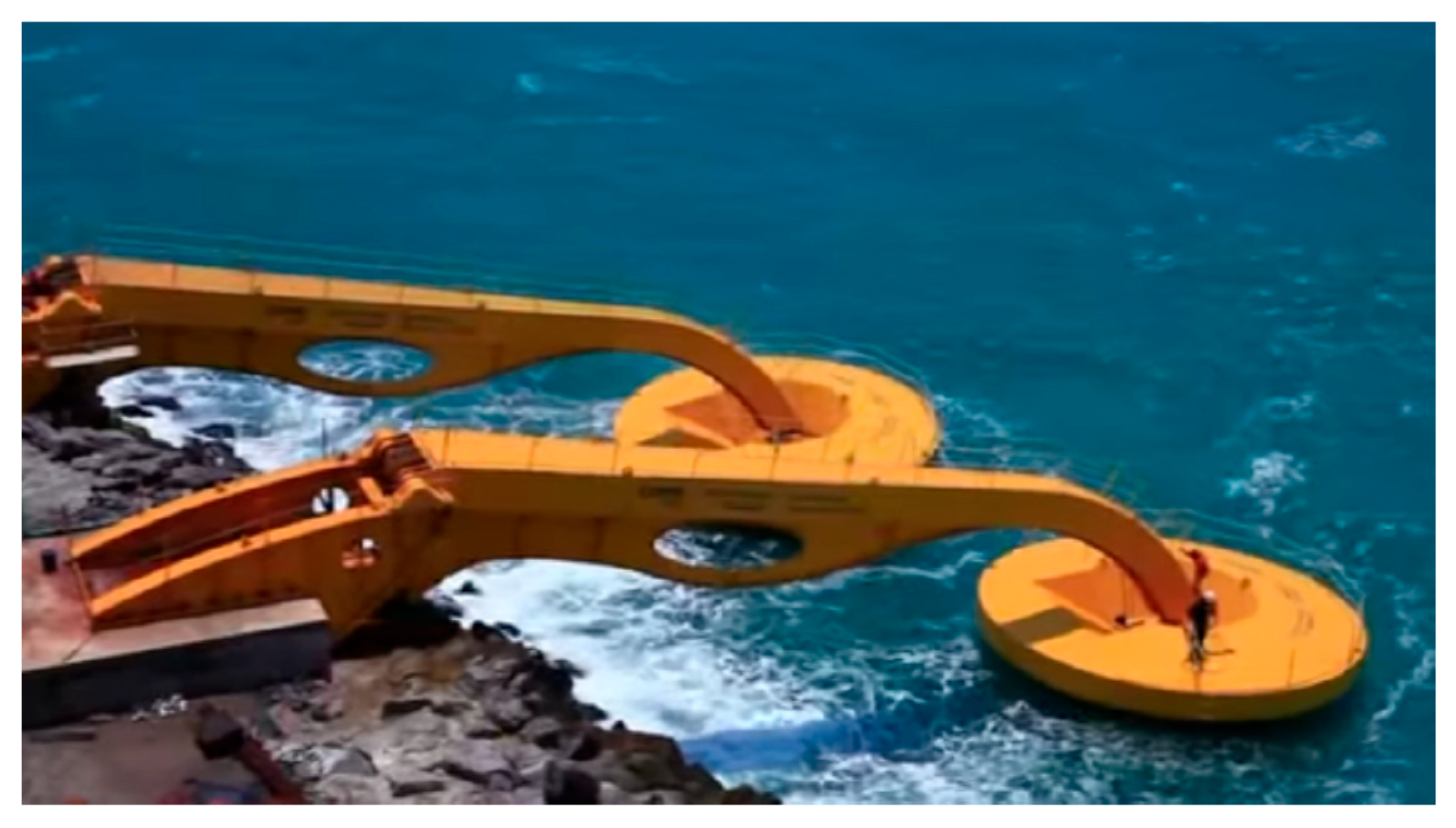
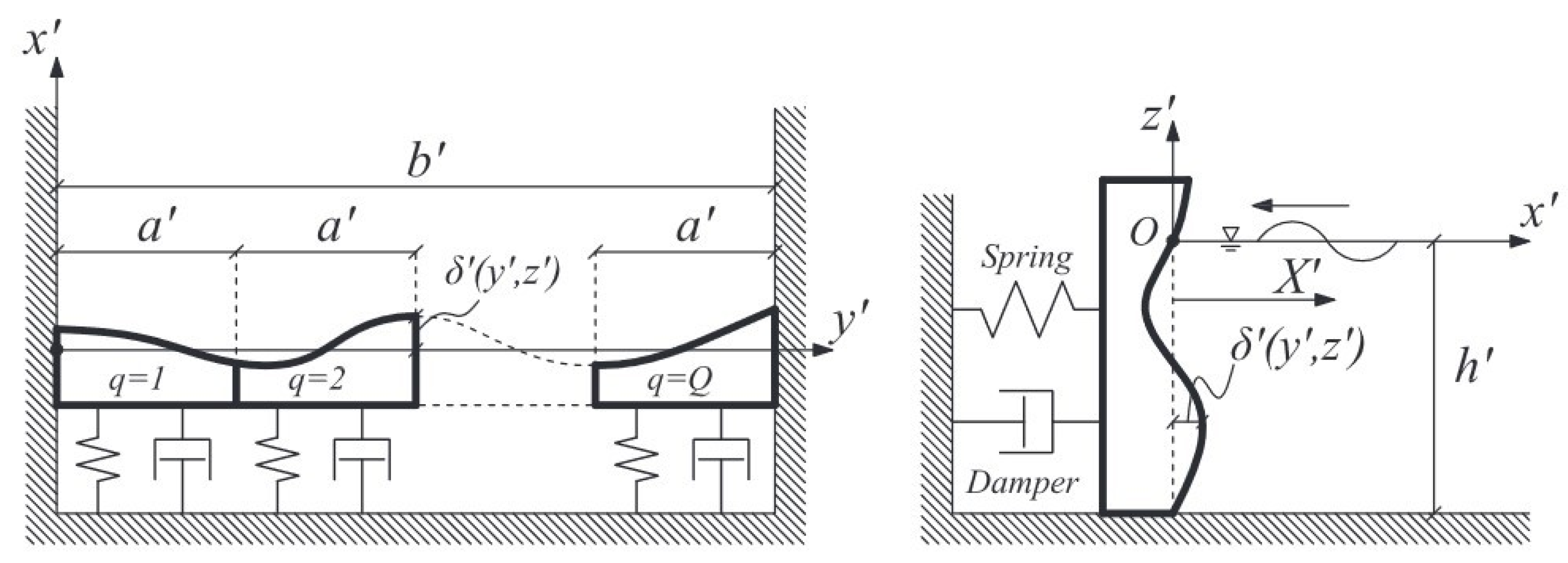
2.2.2. Multi-Resonant Curved Gates

Michele et al. [35] have recently proposed a system of multiple curved gates in a harbour channel, as shown in the conceptual scheme of Figure 6.
Unlike isolated floating bodies, a system of closely spaced gates achieves optimal efficiency when they resonate as a whole. Therefore, it is the articulation of the system that allows such devices to maximise power output [36].
Michele et al. [35,37] developed second and third order theories for arrays of surging gates in a channel and of flapping plates in open sea. They showed that hydrodynamic interactions between weakly nonlinear waves and floating bodies characterised by curved surfaces yield large efficiency ( C F 0.7 in optimal configuration at synchronous resonance). The results obtained in their work show the importance of higher-order contributions, combined with curved WEC surfaces, for extracting energy. Given the presence of higher order wave fields, the capture factor reaches larger values than the theoretical maximum of a simple flat absorber described by the linearised theory. In the case of flapping plates, the authors found that the vertical shape of each WEC is more important than the horizontal curvature in maximising power extraction efficiency. In particular, vertically concave configurations perform significantly better than flat devices of the same type, previously analysed in several works [38,39,40].

3. Hybrid Devices

Hybrid devices are designed to extract energy from multiple sources, such as wave, wind and solar. Particular interest is in integrating wave energy converters in offshore wind farms. As offshore wind is a proven technology, wind–wave hybridisation offers the advantage of sharing infrastructure and maintenance costs, thus decreasing the Levelised Cost of Energy (LCOE) of the wave energy component [41,42,43]. Combining wind and wave power can also be beneficial to mitigate the variability of a single resource, though the feasibility of this concept is still debated [18]. Hybridisation can also include the use of different WEC typologies in the same wave farm. That is realised by using WECs that work in different modes with different resonant periods, such as for example heaving buoys and surging gates, in order to achieve a broader frequency response of the system.
At the moment, hybrid devices have not yet achieved commercial maturity. In the following, we first review some of the technologies that have reached offshore test stage, and then describe several concepts under development.

3.1. Existing Concepts

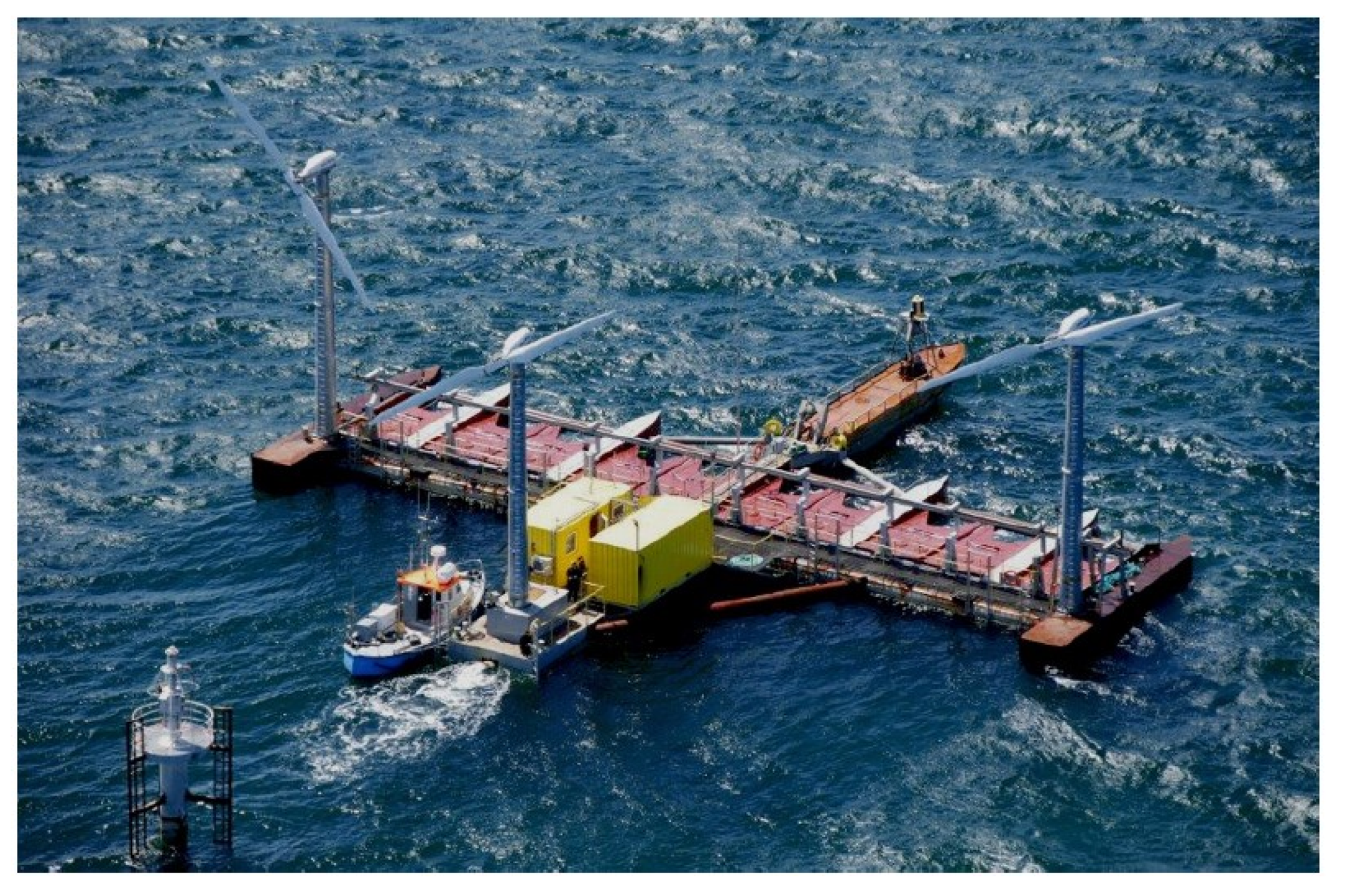
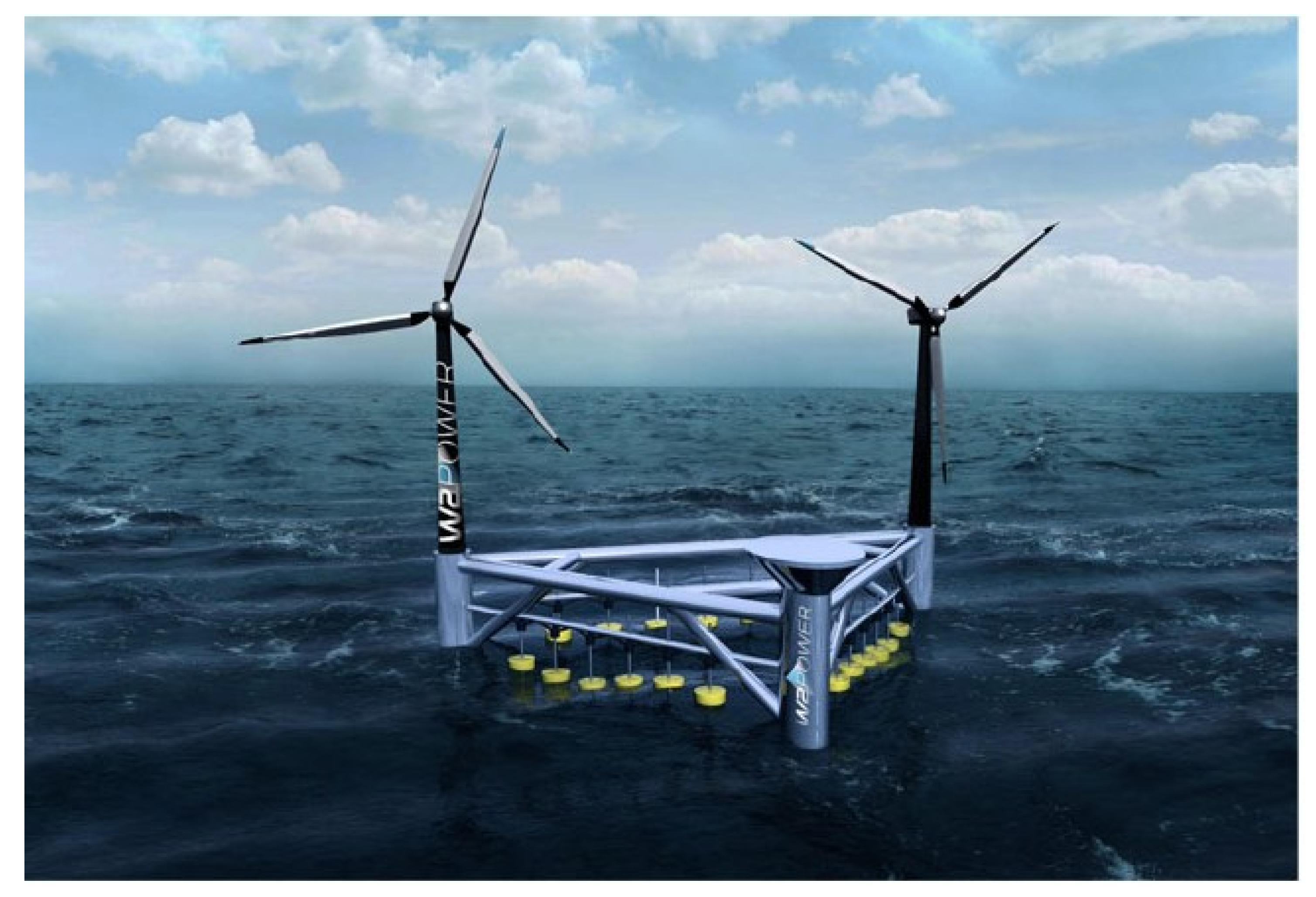
Hybrid Wind–Wave Platforms

The first hybrid wind–wave concept dates back to 1995, when Danish company Floating Power Plant (FPP) invented the Poseidon, a floating platform where rotating WABs are installed together with wind turbines [18,44]. A 37 m wide prototype (named P37) was installed offshore in Denmark, comprising 3 offshore wind turbines (11 kW each) and 10 WECs (3 kW each), see Figure 7. The platform was connected to the grid and delivered electricity from both wind and waves. The device was also modelled with a combined HAWC2 (Horizontal Axis Wind turbine simulation Code, second generation)–WAMIT interface at the Technical University of Denmark (DTU) [45].
Over the testing period (2008–2013), the system achieved a capture width (i.e., the ratio between the power output and the incident wave power per unit metre) of 60–80% and an average 30% conversion ratio between the captured wave energy and the produced electricity [18]. FPP is now developing a new floating semi-submersible platform integrating a single wind turbine (4–15 MW) and four WECs (2–4 MW). The platform is designed to rotate passively to face the incoming waves, thus allowing the WECs to absorb up to 80% of the incident wave power [46].
The W2Power is a hybrid wind–wave energy converter proposed by Norwegian company Pelagic Power. The device combines two offshore wind turbines and multiple oscillating body WECs on the same semi-submersible platform [47]. The platform has a triangular shape, with the two turbines installed on two buoyancy columns, and the third column hosting the PTO system [48]. Arrays of WECs (oscillating buoys) are installed along the sides, the longer side being about 90 m long, as shown in Figure 8. With the support of FP7 MARINET, W2Power completed five laboratory test campaigns in Edinburgh and Cork, at scale 1:100. A numerical model of the device, based on SeaFEM, is also available [48]. A 1:6 scale device without WECs was tested near the Canary Islands, but no power data is available [44]. According to Pelagic Power’s description, the full-scale device will feature two 3.6 MW offshore wind turbines and floating WECs for a rated power of 10 MW in total [47].

3.2. Concepts under Development

3.2.1. Hybrid Wind–Wave

A hybrid wind–wave system has been recently developed by the University of Plymouth, integrating an OWC with jacket-frame or monopile types of offshore wind structure. The geometry includes the presence of a “skirt” connected to the OWC to maximise power extraction, see Figure 9.
Experiments were carried out on a 1:50th scale model to characterise the hydrodynamic response of the OWC sub-system [50,51]. Michele et al. [49] developed a mathematical model of the device. The authors first solved the monochromatic problem in terms of Bessel functions, then extended the theory to the case of random sea states. They found that the larger the skirt height, the larger the efficiency when the piston-like motions (or Helmholtz modes) resonate, whereas the sloshing resonant peaks are almost unaffected. Concerning the opening angle of the skirt, the authors obtained that the optimal configuration maximising energy extraction corresponds to π rad, i.e., when the skirt extends for half the circumference of the chamber. Michele et al. also analysed the OWC response to an incident wave spectrum of the JONSWAP type and showed that the broad range of wave frequencies does not pair well with the narrow peaks of the resonant sloshing modes. This is less so for the broadband Helmholtz-pumping mode at lower frequencies. In this case, large radiation damping is possible and the shape of the resonant peak is not affected significantly. Outside resonance, the device efficiency is comparable to or larger than that of the monochromatic case, as shown in Figure 10.
Recently, the Australian company Bombora has entered into an agreement with Technip FMC to develop a hybrid wind–wave energy converter, named inSPIRE, consisting of a floating offshore wind foundation which incorporates Bombora’s mWave, a flexible WEC described in Section 5. The project will articulate in two phases: Phase 1 will test a combined wind turbine (8 MW) and mWave (4 MW) system, for a total of 12 MW, whereas Phase 2 will scale up to 18 MW (6 MW wave and 12 MW wind). A grid-connected demonstrator is planned to be commissioned by 2023 [52].
Wales based company Marine Power System has integrated its WEC WaveSub with wind turbine technology to create the wave–wind hybrid system DualSub, with 20 MW+ capacity target [53].

3.2.2. Hybrid Wec Farms

Hybrid WEC farms include several WEC archetypes, with the idea of combining different extraction mechanisms to maximise the power production of the farm. Sarkar et al. [54] proposed a hybrid WEC farm comprising both offshore and nearshore device archetypes. The offshore devices are heaving buoys WECs (HWECs) of the point-absorber type, whereas the nearshore devices are Oscillating Wave Surge Converters (OWSC), a terminator-type device made by a flapping plate. Sarkar et al. [54] performed a preliminary modelling study on the interplay between one HWEC and one OWSC. They found that strong interactions between the two converters can develop at certain frequencies, influencing particularly the performance features of the HWEC. Depending on the relative position of the devices and the angle of incidence of the waves, however, strong destructive effects can also arise, deteriorating the performance of the system. Concerning interactions between multiple devices of different types, a comprehensive review on the state of the art of wave energy park modelling has been recently presented by Göteman et al. [55].

4. Devices for Special Applications

WECs have also been developed for use in applications where the main focus is not necessarily wave energy extraction. Areas of implementation include offshore oil and gas, desalination, island microgrids, artificial reefs, coastal protection and aquaculture.

4.1. Offshore and Subsea Applications

4.1.1. Wave-Activated Bodies

Wave-activated bodies (WABs) have found recent application to provide power to offshore platforms. Italian company ENI Group, one of the largest oil and gas companies in the world, have pioneered the application of small-scale WECs to support operations in their offshore platforms. In 2018, Ocean Power Technology (OPT) teamed with ENI to deploy their Power Buoy point absorber as a charging point and communications device for offshore platforms [56]. Later, ENI developed their own device, named ISWEC (Inertial Sea Wave Energy Converter), in collaboration with Wave for Energy S.r.l, a spin-off of the Politecnico di Torino. ISWEC is a pitching device equipped with two gyroscopic systems that are connected to a generator. A pilot plant was built in Ravenna (Italy), with a nominal power output of 50 kW. ENI are now working on an industrial ISWEC model with a nominal power output of 100 kW at peak, to be part of a 12 MW wave farm [57].
Scottish company Mocean Energy has attracted £200,000 worth of funding from Scottish Enterprise and the OGTC (Oil & Gas Technology Centre) to develop a hinged raft WEC, named Blue Star. The device will generate electricity from wave energy to power subsea equipment, such as control systems and autonomous underwater vehicles (AUV) for applications in oil and gas [58]. A novel 20-m long, 38-tonne wave machine called Blue X has been deployed at EMEC’s large scale Billia Croo test site in summer 2021. Mocean Energy plans to connect the device to a subsea battery, which will power a remotely operated autonomous underwater vehicle.

4.1.2. Piezoelectric Converters

The use of piezoelectric materials in the context of wave energy extraction has been advocated in the last decade [12,59,60,61,62]. Piezoelectric ceramics can establish a voltage under the application of an external stress, and thus are able to exploit cycles of stresses and strains induced by incoming waves to generate an output voltage. Piezoelectric WECs (PWECs) offer the advantage of embedding the power take-off mechanism directly into the prime mover (usually a flexible piezoelectric membrane), thus reducing the amount of mechanical connections present in the device. Technical schemes of several proposed PWEC technologies are available in the detailed reviews of Jbaily and Yeung [63] and Kiran et al. [64]. The power generated by a typical piezoelectric WEC is in the order of kW, which is enough to supply small appliances, sensors and offshore buoys.
Mutsuda et al. [60] developed an Ocean Power Generator using flexible piezoelectric sheets, named EFHAS (Elastic Floating unit with HAnging Structures), shown in Figure 11.
EFHAS consists of a floating section, made by floats interconnected through the use of flexible piezoelectric devices (FPED), and by a hanging section. The FPED parts are made of a polyvinyledene fluoride film (PVDF, thickness 40–100 μm) attached to an elastic rubber substrate. The floating unit harvests wave energy mainly mechanically (e.g., as a system of interconnected point absorbers), whereas the hanging unit extracts energy from currents and vortexes by exploiting the piezoelectric effect. The concept was tested experimentally at 1:50 scale using a system of nine floats (diameter 25 cm) connected to a larger float (diameter 50 cm), with a hanging unit about 60 cm long. The electric power per surface area generated by the hanging unit was measured with amplifier and PC, ranging up to 40 mW / m 2 [60].
Renzi [62] developed a coupled hydroelectromechanical model of a PWEC made by a long flexible bimorph plate, clamped at the ends and set into motion by incident waves, as shown in Figure 12.
In the bimorph configuration, piezoelectric layers are attached to each face of a flexible substrate made by silicon rubber. Thin electrodes are placed on both faces of the piezoelectric layers, establishing a potential difference across the device. The model highlights the existence of a coupled system of short and long flexural waves that travel along the flexible plate. Such waves force the plate to vibrate in small wavelength oscillations, which are slowly modulated by the long wave component. The small wavelength component determines the occurrence of resonant peaks in the power curve, as shown in Figure 13.
In particular, there are clear resonant peaks at which the power production is in the order of kW/m. Later, Buriani and Renzi [12] extended the concept to model a PWEC moored on a bottom-seated breakwater. They found that the interaction with the breakwater further enhances the resonant peaks of the device. More recently, Zheng et al. [65] considered a PWEC integrated in a floating breakwater. The change of the breakwater width/draft was found to have limited influence on wave power absorption of the PWEC. The edge condition (simply supported and clamped edge conditions) and width of the PWEC are two key factors affecting the performance of the device [65]. These works [12,62,65] are all in the two-dimensional setting, i.e., one horizontal and one vertical dimension. For the applications of PWEC in offshore regions, a three-dimensional (3D) consideration may be required. Zheng et al. [66] developed a 3D theoretical model and studied the hydrodynamic performance of a circular PWEC. It was revealed that a circular PWEC with a small radius generally provides a better performance in terms of the average wave power that can be absorbed per unit area of the device. However, to exploit the short wavelength resonances, the flexible plate must still be tens of metres long, and the piezoelectric film should cover the substrate uniformly, which is difficult to achieve by using off-the-shelf piezoelectric patches [62]. The recent development of piezoelectric paint that can be sprayed directly on the substrate seems to be a promising solution to overcome such impediments [67].

4.2. Other Applications

4.2.1. Desalination

One of the most promising areas of development is the use of wave energy for desalination. This is becoming a competitive solution in those areas of the world with scarcity of potable water and availability of significant wave resource. Australian company Carnegie Clean Energy developed a wave-powered Desalination Pilot Plant (DPP) on Garden Island, Western Australia. The facility opened in April 2014 as the first commercial-scale wave powered desalination project, and uses Carnegie’s CETO wave activated converters to power a seawater reverse osmosis (SWRO) process, see Figure 14 and Ref. [68]. The DPP production capacity is about 150 m3 of potable water per day [69]. Other WEC-powered desalination projects that have achieved demonstration stage include Odysée (Canada) and Saros (USA), see [1].

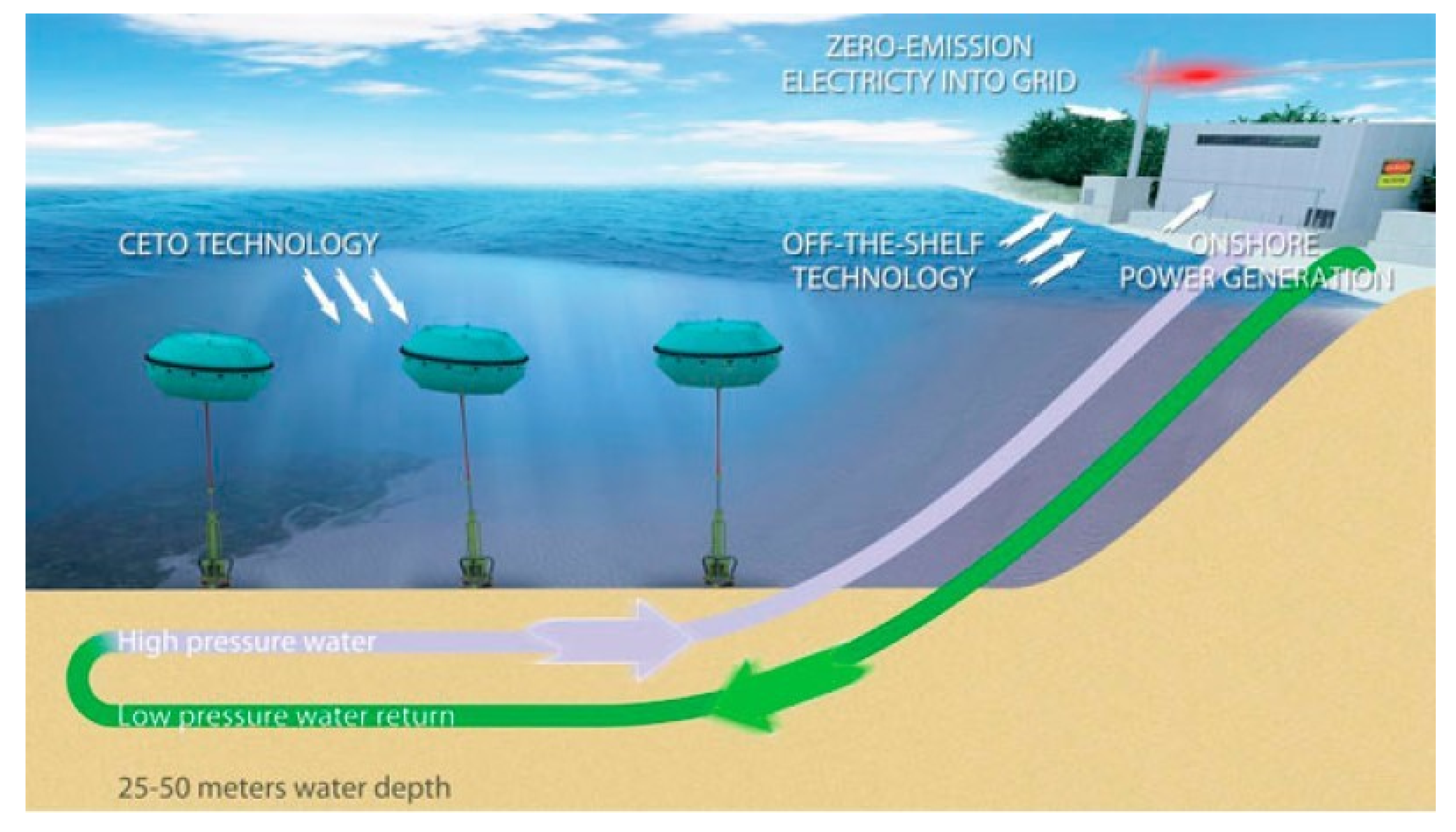
4.2.2. Island Microgrids

Wave energy conversion is an immediate viable alternative to fossil fuels in remote islands, where there are heavy fiscal burdens associated with importing fuels. Two pilot projects have been developed in Australia. The first, completed by Carnegie Clean Energy in Garden Island, complements the desalination plant described above with three 1 MW wave buoys, a 2 MW solar Photo-voltaic array, and a 2 MW battery, powering Australia’s largest naval base, HMAS Stirling [1]. The second project is being developed by Wave Swell, who deployed a 200 kW demonstrator OWC, named UniWave200, on King Island in January 2021. The device is expected to be connected to Hydro Tasmania’s hybrid grid in 2021 [70,71,72].

4.2.3. Aquaculture

UK company CCell are developing a wave paddle (a curved flap-type device) to grow coral reefs. A system of paddle WECs powers a low-voltage current through a steel structure. Seawater minerals are drawn to the structure, forming limestone rock around it, on which coral colonies are attached [73]. Other applications in aquaculture include Smalle Technologies eForcis and Albatern’s WaveNET arrays for powering fish farms [1].

5. Flexible Devices

Flexible WECs use deformable prime movers, instead of traditional rigid bodies, to drive the PTO system. This has the advantage of reducing the number of moving metallic parts, which were responsible for severe failure during sea trials of several rigid WECs [18,62]. The first flexible device concepts were introduced back in the 1980’s by J.M. French (Lancaster Flexible Bag) and N. Bellamy (Circular Clam). Such devices featured a series of inflatable bags filled with air, that would expand and contract following the oscillatory motion of the incoming waves. This motion would pump air into a turbine connected to a generator [18]. During the past decade, the development of flexible devices has been accelerated by the advent of highly performing elastic materials, such as dielectric elastomers, flexible piezoelectric bimorphs and flexible fabrics [74,75]. Recently, UK Research and Innovation (UKRI) have awarded funding to two projects (one led by the University of Plymouth, the other by the University of Strathclyde) that will explore the use of flexible materials to improve performance, survivability and reliability of WECs [76]. In the following, we shall first review existing concepts that have undergone lab or sea trials, and then we will discuss some innovative concepts under development.

5.1. Existing Concepts

Various different types of flexible devices have been proposed recently, each with particular characteristics. Here, we follow the classification of Collins et al. [77,78], based on the type of working surface, and group such devices into deformable membranes, bulge wave and carpet membranes. It is to be noted that some deformable membrane WECs (e.g., AWS-III and mWave) have now undergone extensive sea trials and are being scaled up for utility-scale applications.

5.1.1. Deformable Membranes

Scottish company AWS Ocean Energy is developing several flexible devices based on deformable membranes, which exploit the same working principle as the flexible bags described above. A 1:9th scale proof of concept of AWS-III was tested Loch Ness in 2010. The device was made of an array of inflatable cells arranged around a catamaran structure. In 2014, a 1:15th scale model of a dodecagon-shaped AWS-III device was built and then tested at the MARIN test site (The Netherlands) [79]. More recently, the company have proposed a linear configuration, with six cells facing the incoming waves at an angle between 20–40 degrees, and three cells on the other side of the structure [77]. Each cell measures about 16 m wide by 8 m deep, and the nominal power of the device is rated at 2.4 MW [79]. A single power-generating cell was successfully tested in 2014 at Lyness quay, Orkney. According to AWS Ocean Energy, the technology is now ready to progress to full prototype stage [79].
Australian company Bombora has developed a membrane-style WEC, named wWave. The converter features an array of air-inflated membranes, made of industrial grade rubber and mounted on a structure located at a depth of several metres nearshore, as depicted in Figure 15.
As waves pass overhead, each membrane pumps air into a duct, driving a turbine connected to a generator [80]. Tank testing of a 1:15th scale model of the device was conducted at the Australian Maritime College, and a numerical performance modelling suite of the same device is available [81,82]. According to the numerical simulations, the mWave power matrix features a broad peak in performance at wave periods of about 9 s for typical design parameters. Bombora secured a £10.3 m Welsh European Funding Office (WEFO) grant in 2018 to deploy a full-scale 1.5 MW mWave prototype at East Pickard Bay, Wales [2].

5.1.2. Bulge Wave Devices

A bulge wave device is an elastic rubber tube filled with water, submerged under the free surface and aligned perpendicular to the wave crests. As waves pass overhead, they create a pressure differential that drives a bulge along the length of the tube. Matching the resonant frequency of the bulge wave to that of the incident waves maximises power production. The phenomenon is generated by the interaction of the waves, the elastic tube and the internal fluid, and is similar to the pumping of blood in arteries [83,84].
English company Checkmate Seaenergy developed Anaconda, a bulge wave device originally invented by F. Farley [83], where the elastic tube terminates with a turbine connected to a generator, though later developments also considered the use of a PTO system distributed along the WEC. Figure 16 shows an artist’s sketch of the Anaconda concept.
An initial set of tank tests on a 1:25th scale model were performed in the deep offshore wave basin at the Danish Hydraulic Institute [85]. Later tests at the same scale were also undertaken at Southampton Solent University, without PTO optimisation [86]. Linear and nonlinear mathematical models of the converter are also available [84,87]. In 2016, Checkmate Seanergy conducted further experiments at Strathclyde University, supported by the Novel Wave Energy Converter funding campaign by Wave Energy Scotland (WES). In 2017, the company received £730,000 funding from WES within the Tier 2 NWEC2 call to progress the technology further. However, WES decided to stop funding in January 2019, as the project did not progress to Tier 3 level [88].
Figure 16. Artist’s sketch of the Anaconda WEC. Reproduced with permission from [88], Checkmate Seaenergy, 2021.
Energies 14 06537 g016
In 2009, SBM Offshore developed a bulge wave device similar to Anaconda, named S3. Unlike Anaconda, S3 does not have a turbine, but it extracts energy by means of electro active polymers (EAP) fabricated with elastomers and positioned along the device hull. Therefore, in the S3 WEC the prime mover coincides with the PTO system [89]. A proof-of-concept device, 11 m long with 25 EAP generators, was tested in 2010 in the ACRI-IN wave channel in Sophia Antipolis. In 2011, a 10 m long S3 WEC, equipped with 20 independent EAP generators, was tested in the Hydrodynamics and Ocean Engineering Tank of Ecole Centrale de Nantes. Numerical tools were developed to analyse the hydroelastic response of the device [90]. A recent mathematical model has also provided a means to calculate the maximal power absorption of the device based on the waves radiated in the far field. The model shows that the capture width of the S3 WEC is larger when the incident waves are shorter than the device length [91]. Therefore, the S3 WECs needs to be longer than the maximum incident wavelength to optimise power production, which is a strong constraint. Further research needs also to be done on unwanted phenomena that are the direct consequence of using viscoelastic materials, such as hysteresis, stress-softening and strain-induced crystallisation, which can deteriorate the performance of bulge wave devices subject to large deformations [77].

5.1.3. Carpet Membranes

These are large membranes that are free at the end nodes and are moored with tethers or hydraulic pistons. The membrane is deformed by the action of incoming waves, and sets into motion a hydraulic PTO. In 2012, M.-R. Alam of UC Berkley proposed the Wave Carpet, a carpet membrane anchored at the bottom of the ocean, which extracts energy from waves, similar to the way mudflats dissipate incoming waves in the nearshore [92]. A proof-of-concept experiment was carried out in 2013, at the University of California, Berkeley’s OBrian hall, on a model made out of natural rubber, connected to the hydraulic PTO by means of aluminum bars [93]. The proof-of-concept model proved able to absorb almost all of the incident wave energy; however, the maximum PTO efficiency achieved was only 5.6%. An improved version of the converter was later tested in 2014, this time achieving a peak experimental PTO efficiency of 42.3% [94]. In 2019, the U.S. Department of Energy (DOE) awarded funding to CalWave Power Technologies to design the next generation of the Wave Carpet, which will be capable to produce an annual average power output of 45 kW [95].

5.2. Concepts under Development

5.2.1. Flexible Air Bag

Funded by the Engineering and Physical Sciences Research Council (EPSRC), the University of Plymouth have developed a flexible air-filled bag converter. Three different types of axisymmetric devices, all heaving point absorbers, were developed and tested at 1:20th scale in the Plymouth’s COAST Laboratory [96]. Each device features a sealed bag that expands and contracts under the action of incident waves. This breathing motion makes it possible to install a power take-off system inside the device, without any external reference. A mathematical model developed by Kurniawan et al. [97] showed that the amount of air in the bag governs the dynamic response of the device. It is therefore possible to use air volumes that enable matching the resonant period of the device to the peak period of the wave spectrum. When that happens, the flexible bag device can capture up to twice as much power as its rigid counterpart [97].

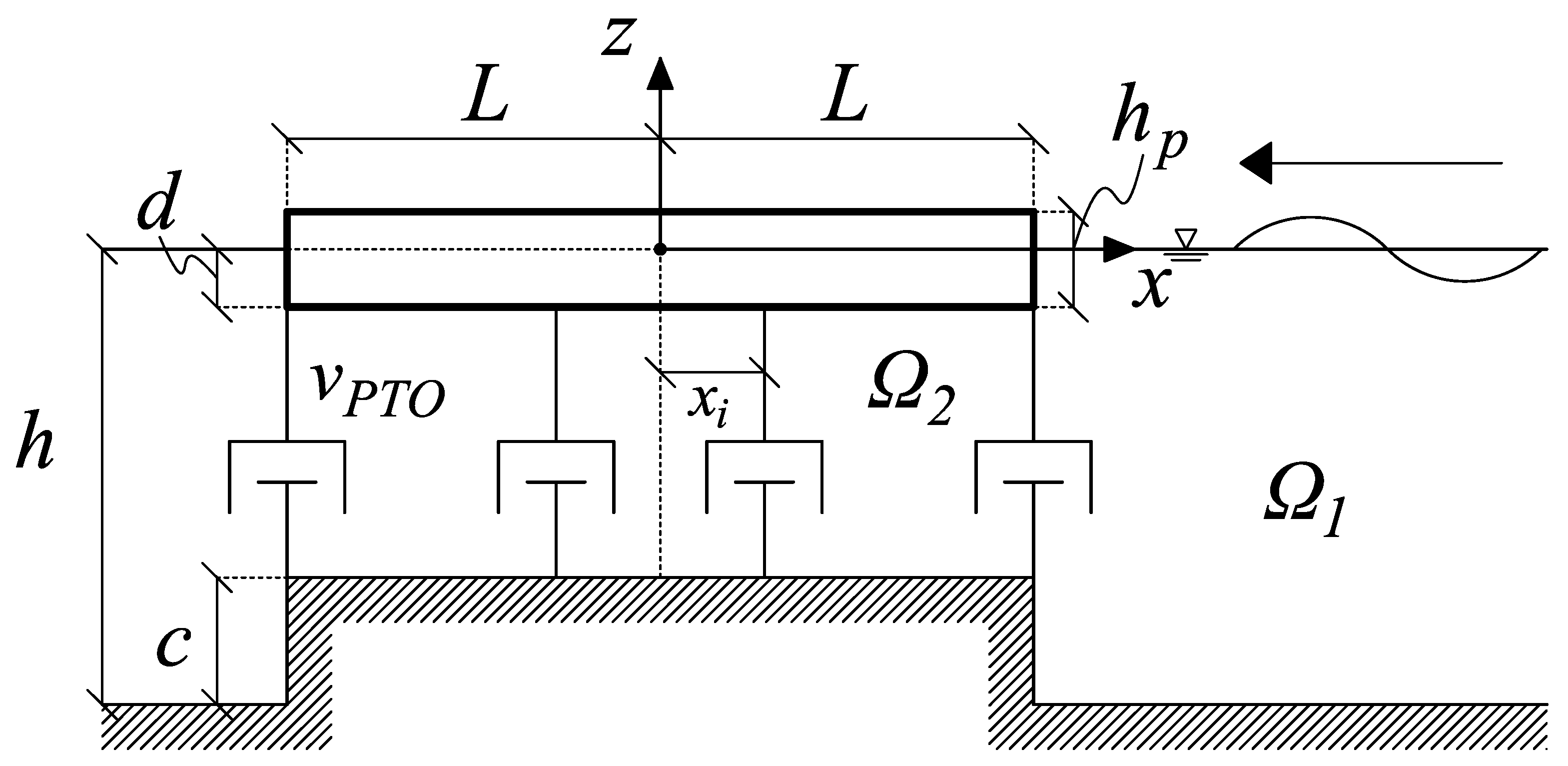
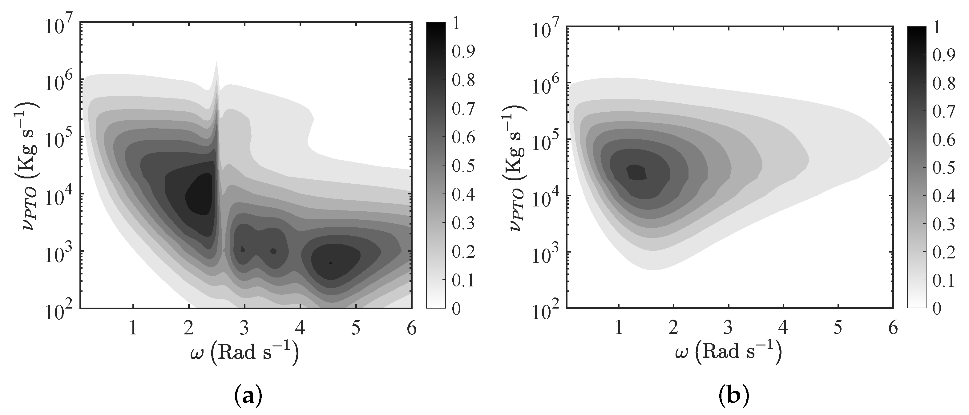
5.2.2. Flexible Floater

Loughborough University, in collaboration with Dutch company Ocean Grazer BV have recently proposed an innovative wave energy converter made by a floating flexible membrane, and connected to a multi-pump, multi-piston power take off system (MP2PTO). Michele et al. [98] developed a novel mathematical model of the system, based on a potential-flow approach. Figure 17 shows a sketch of the conceptual model, where the floater has length 2 L , submergence d, thickness h p and is connected to a series of linear PTO mechanisms (each with power take-off constant ν P T O ), over an ocean of depth h, above a platform of height c.
Michele et al. [98] showed that the bending elastic modes of the flexible floater enhance the energy extraction efficiency of the converter, with respect to the case of a rigid plate of the same dimensions. As an example, Figure 18 shows the behaviour of the Capture Factor versus the frequency of the incident waves, for an elastic and a rigid floater—Figure 18a,b, respectively.
The floaters are 20 m long, with linear PTOs equally spaced every 5 m. The results of Figure 18 show that the flexible WEC features a broad region of local maxima, which is absent in the case of the rigid WEC. This enables the flexible floater WEC to extract energy in a broader frequency range than its rigid counterpart.
An experimental demonstrator of the technology was also developed and tested in the wave tank at the University of Groningen (The Netherlands), see Figure 19.
The demonstrator was made of two layers of red silicone sheets, attached to a 10-piston MP2PTO system and tested in several configurations (see [98] for details). The power output of the device was not measured directly, rather the discharge of each piston was used as a proxy for power. The device achieved 26% Capture Factor with a sub-optimal PTO damping. PTO optimisation would almost certainly allow the device to attain Capture Factor levels closer to the theoretical limits of Figure 18a.

6. Discussion and Conclusions

The wave energy technologies illustrated in the previous sections are summarised in Table 1.
Our review shows that breakwater integrated WECs are at a more advanced stage of development, as compared to other devices for niche applications. This is because breakwater integrated WECs are all based on well established energy conversion technologies, such as oscillating water columns or overtopping devices, whose development started in the mid-1980s [5,18]. The wealth of experience in developing such devices accumulated by the international wave energy community through mathematical and numerical modelling, lab tests and sea trials has made it possible to advance most of the proposed breakwater integrated WECs to an operational stage. However, it is to be noted that the power output of such devices is strongly limited by their nearshore location, where the available wave energy resource is significantly smaller than offshore [5]. Except in very energetic sea states, such as in Mutriku, breakwater-integrated WECs are only capable of extracting a few kilowatts per metre of breakwater length, and their deployment is geographically limited to marinas and harbours.
On the contrary, hybrid wind–wave WECs enjoy greater versatility, as their deployment is less constrained by depth or geographical limitations. Hybrid wind–wave technologies are fast developing, with several devices having reached sea trials or lab test stage in the last decade. Recently, the sector has received substantial funding from the European Commission, including for example the FP7/MARINA platform, in which various hybrid technologies were tested [18]. A new venture launched by TechnipFMC and Bombora aims to push hybrid wind–wave technologies beyond the 10 MW scale, at a predicted LCOE of €50 per MWh, where the company believes it will become competitive for utility scale deployment.
The use of WECs in special applications, such as offshore oil and gas or island microgrids, has a strong potential to support the development of utility-scale projects by accumulating field experience, demonstrating success stories of grid integration and building confidence for stakeholders.
Flexible devices are those developing at the fastest pace, as shown by the large number of new concepts proposed in the last decade (see again Table 1). Such a rapid growth is being fuelled by advancements in materials science, which allow the substitution of heavy metallic components with lightweight flexible materials, such as piezoelectric paints, electro active polymers and highly resistant deformable fabrics. Two technologies, the AWS-III and mWave, are currently emerging as leaders in the sector, and will be soon tested in utility-scale demonstration projects. In the UK, research on flexible devices has been recently boosted by two new projects funded by UKRI at the universities of Plymouth and Strathclyde [76].
At the same time, Table 1 shows that there is lack of a standardised approach to evaluate performance of niche technologies. Many different metrics are being used, such as capture factor, capture width, PTO efficiency, absorption efficiency, etc., which makes it harder for investors to assess and compare the efficiency of the proposed technologies. The establishment of large consortia in marine renewable energy, such as the Supergen ORE Hub in the UK, MaREI in Ireland and the Marine Energy Council in the U.S. is seen as instrumental to provide leadership and direction in order to standardise metrics for performance evaluation.

Author Contributions

Conceptualization, E.R.; investigation, E.R., S.M., S.Z., S.J., D.G.; writing—original draft preparation, E.R., S.Z., S.J.; writing—review and editing, E.R., S.M., S.Z., S.J., D.G.; funding acquisition, E.R., S.M., D.G. All authors have read and agreed to the published version of the manuscript.

Funding

E.R. and S.M.’s research was funded by a Royal Society—CNR International Fellowship, UK (Grant NF170771). D.G. and S.J. gratefully acknowledge the EPSRC for supporting part of this work through EP/S000747/1.

Institutional Review Board Statement

Not applicable.

Informed Consent Statement

Not Applicable.

Data Availability Statement

All data used in this study are made available in the paper.

Conflicts of Interest

The authors declare no conflict of interest. The funders had no role in the design of the study; in the collection, analyses, or interpretation of data; in the writing of the manuscript, or in the decision to publish the results.

Abbreviations

The following abbreviations are used in this manuscript:
DEGDielectric elastomer generator
DMDeformable membrane
EAPElectro active polymers
LCOELevelised cost of energy
OTDOvertopping device
OWCOscillating water column
PTOPower take-off
WABWave activated body
WECWave energy converter

References

  1. Supergen Offshore Renewable Energy. Wave Energy Innovation Position Paper, UK. 2021. Available online: https://supergen-ore.net/uploads/resources/Wave_Energy_Innovation_-_Position_Paper.pdf (accessed on 9 October 2021).
  2. Jin, S.; Greaves, D. Wave energy in the UK: Status review and future perspectives. Renew. Sustain. Energy Rev. 2021, 143, 110932. [Google Scholar] [CrossRef]
  3. U.S. Power Sector Is Halfway to Zero Carbon Emissions. Available online: https://newscenter.lbl.gov/2021/04/13/u-s-power-sector-is-halfway-to-zero-carbon-emissions/ (accessed on 20 July 2021).
  4. Our World in Data. Available online: https://ourworldindata.org/grapher/installed-solar-pv-capacity (accessed on 20 July 2021).
  5. Greaves, D.; Iglesias, G. Wave and Tidal Energy; Wiley: London, UK, 2018. [Google Scholar]
  6. Babarit, A. A database of capture width ratio of wave energy converters. Renew. Energy 2015, 80, 610–628. [Google Scholar] [CrossRef] [Green Version]
  7. Evans, D.V. Wave-power absorption by systems of oscillating surface pressure distributions. J. Fluid Mech. 1982, 114, 481–499. [Google Scholar] [CrossRef]
  8. Koutrouveli, T.I.; Di Lauro, E.; das Neves, L.; Calheiros-Cabral, T.; Rosa-Santos, P.; Taveira-Pinto, F. Proof of Concept of a Breakwater-Integrated Hybrid Wave Energy Converter Using a Composite Modelling Approach. J. Mar. Sci. Eng. 2021, 9, 226. [Google Scholar] [CrossRef]
  9. Ning, D.Z.; Zhano, X.L.; Chen, L.F.; Zhao, M. Hydrodynamic Performance of an Array of Wave Energy Converters Integrated with a Pontoon-Type Breakwater. Energies 2018, 11, 685. [Google Scholar] [CrossRef] [Green Version]
  10. Zhao, X.; Zhang, Y.; Li, M.; Johanning, L. Experimental and analytical investigation on hydrodynamic performance of the comb-type breakwater-wave energy converter system with a flange. Renew. Energy 2021, 172, 392–407. [Google Scholar] [CrossRef]
  11. Sarkar, D.; Renzi, E.; Dias, F. Effect of a straight coast on the hydrodynamics and performance of the Oscillating Wave Surge Converter. Ocean Eng. 2015, 105, 25–32. [Google Scholar] [CrossRef] [Green Version]
  12. Buriani, F.; Renzi, E. Hydrodynamics of a Flexible Piezoelectric Wave Energy Harvester Moored on a Breakwater. In Proceedings of the 12th European Wave and Tidal Energy Conference (EWTEC 2017), Cork, Ireland, 27 August–1 September 2017. [Google Scholar]
  13. Vicinanza, D.; Di Lauro, D.; Contestabile, P.; Gisonni, C.; Lara, J.L.; Losada, I.J. Review of Innovative Harbor Breakwaters for Wave-Energy Conversion. J. Waterw. Port Coast. Ocean Eng. 2019, 145, 03119001. [Google Scholar] [CrossRef]
  14. Power Technology. Available online: https://www.power-technology.com/projects/mutriku-wave/ (accessed on 5 July 2021).
  15. Garrido, A.J.; Otaola, E.; Garrido, I.; Lekube, J.; Maseda, F.J.; Liria, P.; Mader, J. Mathematical Modeling of Oscillating Water Columns Wave-Structure Interaction in Ocean Energy Plants. Math. Probl. Eng. 2015, 2015, 727982. [Google Scholar] [CrossRef] [Green Version]
  16. McCormick, M.E. Ocean Wave Energy Conversion; Wiley Interscience: New York, NY, USA, 1981. [Google Scholar]
  17. Falcao, A.F.O.; Henriques, J.C.C. Oscillating-water-column wave energy converters and air turbines: A review. Renew. Energy 2016, 85, 1391–1424. [Google Scholar] [CrossRef]
  18. Babarit, A. Ocean Wave Energy Conversion; Elsevier: Amsterdam, The Netherlands, 2018. [Google Scholar]
  19. Boccotti, P. Comparison between a U-OWC and a conventional OWC. Ocean Eng. 2007, 34, 799–805. [Google Scholar] [CrossRef]
  20. Strati, F.M.; Malara, G.; Arena, F. Performance optimization of a U-Oscillating-Water-Column wave energy harvester. Renew. Energy 2016, 99, 1019–1028. [Google Scholar] [CrossRef]
  21. Malara, G.; Romolo, A.; Fiamma, V.; Arena, F. On the modelling of water column oscillations in U-OWC energy harvesters. Renew. Energy 2017, 101, 964–972. [Google Scholar] [CrossRef]
  22. Ning, D.; Guo, B.; Wang, R.; Vyzikas, T.; Greaves, D. Geometrical investigation of a U-shaped oscillating water column wave energy device. Appl. Ocean Res. 2020, 97, 102105. [Google Scholar] [CrossRef]
  23. Gurnari, L.; Filianoti, P.G.F.; Torresi, M.; Camporeale, S.M. The Wave-to-Wire Energy Conversion Process for a Fixed U-OWC Device. Energies 2020, 13, 283. [Google Scholar] [CrossRef] [Green Version]
  24. Arena, F.; Fiamma, V.; Laface, V.; Malara, G.; Romolo, A.; Viviano, A.; Sannino, G.; Carillo, A. Installing U-OWC devices along Italian coasts. In Proceedings of the ASME 2013 32nd International Conference on Ocean Offshore and Arctic Engineering (OMAE2013), Nantes, France, 9–14 June 2013. [Google Scholar]
  25. Arena, F.; Romolo, A.; Malara, G.; Fiamma, V.; Laface, V. The first full operative U-OWC plants in the port of Civitavecchia. In Proceedings of the ASME 2017 36th International Conference on Ocean, Offshore and Arctic Engineering (OMAE2017), Trondheim, Norway, 25–30 June 2017. [Google Scholar]
  26. Moretti, G.; Malara, G.; Scialó, A.; Daniele, L.; Romolo, A.; Vertechy, R.; Fontana, M.; Arena, F. Modelling and field testing of a breakwater-integrated U-OWC wave energy converter with dielectric elastomer generator. Renew. Energy 2020, 146, 628–642. [Google Scholar] [CrossRef]
  27. Vicinanza, D.; Nørgaard, J.H.; Contestabile, P.; Andersen, T.L. Wave loadings acting on overtopping breakwater for energy conversion. J. Coast. Res. 2013, 65, 1669–1674. [Google Scholar] [CrossRef]
  28. Vicinanza, D.; Contestabile, P.; Nørgaard, J.; Lykke-Andersen, T. Innovative rubble mound breakwaters for overtopping wave energy conversion. Coast. Eng. 2014, 88, 154–170. [Google Scholar] [CrossRef]
  29. Contestabile, P.; Iuppa, C.; Di Lauro, E.; Cavallaro, L.; Andersen, T.L.; Vicinanza, D. Wave loadings acting on innovative rubble mound breakwater for overtopping wave energy conversion. Coast. Eng. 2017, 122, 60–74. [Google Scholar] [CrossRef]
  30. Contestabile, P.; Crispino, G.; Di Lauro, E.; Ferrante, V.; Gisonni, C.; Vicinanza, D. Overtopping breakwater for wave Energy Conversion: Review of state of art, recent advancements and what lies ahead. Renew. Energy 2020, 147, 705–718. [Google Scholar] [CrossRef]
  31. Iuppa, C.; Contestabile, P.; Cavallaro, L.; Foti, E.; Vicinanza, D. Hydraulic Performance of an Innovative Breakwater for Overtopping Wave Energy Conversion. Sustainability 2016, 8, 1226. [Google Scholar] [CrossRef] [Green Version]
  32. Cascajo, R.; García, E.; Quiles, E.; Correcher, A.; Morant, F. Integration of Marine Wave Energy Converters into Seaports: A Case Study in the Port of Valencia. Energies 2019, 12, 787. [Google Scholar] [CrossRef] [Green Version]
  33. Cabral, T.; Clemente, D.; Rosa-Santos, P.; Taveira-Pinto, F.; Morais, T.; Belga, F.; Cestaro, H. Performance Assessment of a Hybrid Wave Energy Converter Integrated into a Harbor Breakwater. Energies 2020, 13, 236. [Google Scholar] [CrossRef] [Green Version]
  34. Calheiros-Cabral, T.; Clemente, D.; Rosa-Santos, P.; Taveira-Pinto, F.; Ramos, V.; Morais, T.; Cestaro, H. Evaluation of the annual electricity production of a hybrid breakwater-integrated wave energy converter. Energy 2020, 213, 118845. [Google Scholar] [CrossRef]
  35. Michele, S.; Renzi, E.; Sammarco, P. Weakly nonlinear theory for a gate-type curved array in waves. J. Fluid Mech. 2019, 869, 238–263. [Google Scholar] [CrossRef] [Green Version]
  36. Renzi, E.; Dias, F. Motion-resonant modes of large articulated damped oscillators in waves. J. Fluid Struct. 2014, 49, 705–715. [Google Scholar] [CrossRef] [Green Version]
  37. Michele, S.; Renzi, E. A second-order theory for an array of curved wave energy converters in open sea. J. Fluid Struct. 2019, 88, 315–330. [Google Scholar] [CrossRef]
  38. Renzi, E.; Dias, F. Resonant behaviour of an oscillating wave energy converter in a channel. J. Fluid Mech. 2012, 701, 482–510. [Google Scholar] [CrossRef] [Green Version]
  39. Renzi, E.; Dias, F. Hydrodynamics of the oscillating wave surge converter in the open ocean. Eur. J. Mech. (B/Fluids) 2013, 41, 1–10. [Google Scholar] [CrossRef] [Green Version]
  40. Renzi, E.; Abdolali, A.; Bellotti, G.; Dias, F. Wave-power absorption from a finite array of oscillating wave surge converters. Renew. Energy 2014, 63, 55–68. [Google Scholar] [CrossRef] [Green Version]
  41. Pérez-Collazo, C.; Greaves, D.; Iglesias, G. A review of combined wave and offshore wind energy. Renew. Sustain. Energy Rev. 2015, 42, 141–153. [Google Scholar] [CrossRef] [Green Version]
  42. Hu, J.; Zhou, B.; Vogel, C.; Liu, P.; Willden, R.; Sun, K.; Zang, J.; Geng, J.; Jin, P.; Cui, L.; et al. Optimal design and performance analysis of a hybrid system combing a floating wind platform and wave energy converters. Appl. Energy 2020, 269, 114998. [Google Scholar] [CrossRef]
  43. Talaat, M.; Farahat, M.A.; Elkholy, M.H. Renewable power integration: Experimental and simulation study to investigate the ability of integrating wave, solar and wind energies. Energy 2019, 170, 668–682. [Google Scholar] [CrossRef]
  44. McTiernan, K.L.; Sharman, K.T. Review of Hybrid Offshore Wind and Wave Energy Systems. J. Phys. Conf. Ser. 2020, 1452, 012016. [Google Scholar] [CrossRef]
  45. Yde, A.; Larsen, T.J.; Hansen, A.M.; Fernandez, M.; Bellew, S. Comparison of Simulations and Offshore Measurement Data of a Combined Floating Wind and Wave Energy Demonstration Platform. J. Ocean. Wind Energy 2015, 2, 129–137. [Google Scholar] [CrossRef]
  46. Floating Power Plant. Available online: https://www.floatingpowerplant.com/ (accessed on 7 July 2021).
  47. W2Power. Available online: http://www.pelagicpower.no/ (accessed on 13 July 2021).
  48. Legaz, M.J.; Coronil, D.; Mayorga, P.; Fernandez, J. Study of a hybrid renewable energy platform: W2Power. In Proceedings of the ASME 2018 37th International Conference on Ocean, Offshore and Arctic Engineering OMAE2018, Madrid, Spain, 17–22 June 2018. [Google Scholar]
  49. Michele, S.; Renzi, E.; Perez-Collazo, C.; Greaves, D.; Iglesias, G. Power extraction in regular and random waves from an OWC in hybrid wind–wave energy systems. Ocean Eng. 2019, 191, 106519. [Google Scholar] [CrossRef]
  50. Perez-Collazo, C.; Greaves, D.; Iglesias, G. Hydrodynamic response of the WEC sub-system of a novel hybrid wind–wave energy converter. Energy Convers. Manag. 2018, 171, 307–325. [Google Scholar] [CrossRef]
  51. Perez-Collazo, C.; Greaves, D.; Iglesias, G. A novel hybrid wind–wave energy converter for jacket frame substructures. Energies 2018, 11, 637. [Google Scholar] [CrossRef] [Green Version]
  52. Integrated Semi-Submersible Platform with Innovative Renewable Energy. Available online: https://www.inspireoffshoreenergy.com/ (accessed on 19 July 2021).
  53. Harnessing Waves and Wind. Available online: https://www.marinepowersystems.co.uk/dualsub/ (accessed on 4 September 2021).
  54. Sarkar, D.; Renzi, E.; Dias, F. Interactions Between an Oscillating Wave Surge Converter and a Heaving Wave Energy Converter. J. Ocean Wind Energy 2014, 1, 135–142. [Google Scholar]
  55. Göteman, M.; Giassi, M.; Engström, J.; Isberg, J. Advances and Challenges in Wave Energy Park Optimization—A Review. Front. Energy Res. 2020, 8, 26. [Google Scholar] [CrossRef] [Green Version]
  56. Ocean Power Technologies. Available online: https://oceanpowertechnologies.com/oil-gas-2/ (accessed on 19 July 2021).
  57. ISWEC: Energy from the Sea. Available online: https://www.eni.com/en-IT/operations/iswec-eni.html (accessed on 19 July 2021).
  58. Wave Energy Converter. Available online: https://www.mocean.energy/wave-energy-converter/ (accessed on 19 July 2021).
  59. Wu, N.; Wang, Q.; Xie, X.D. Ocean wave energy harvesting with a piezoelectric coupled buoy structure. Appl. Ocean Res. 2015, 50, 110–118. [Google Scholar] [CrossRef]
  60. Mutsuda, H.; Watanabe, R.; Azuma, S.; Tanaka, Y.; Doi, Y. Ocean Power Generator Using Flexible Piezoelectric Device. In Proceedings of the ASME 2013 32nd International Conference on Ocean, Offshore and Arctic Engineering OMAE2013, Nantes, France, 9–14 June 2013. [Google Scholar]
  61. Tanaka, Y.; Oko, T.; Mutsuda, H.; Patel, R.; McWilliam, S.; Popov, A. An experimental study of wave power generation using a flexible piezoelectric device. J. Ocean Wind Energy 2015, 2, 28–36. [Google Scholar]
  62. Renzi, E. Hydroelectromechanical modelling of a piezoelectric wave energy converter. Proc. R. Soc. A 2016, 472, 20160715. [Google Scholar] [CrossRef] [Green Version]
  63. Jbaily, A.; Yeung, R.W. Piezoelectric devices for ocean energy: A brief survey. J. Ocean Eng. Mar. Energy 2015, 1, 101–118. [Google Scholar] [CrossRef] [Green Version]
  64. Kiran, M.R.; Farrok, O.; Abdullah-Al-Mamun, M.; Islam, M.R.; Xu, W. Progress in Piezoelectric Material Based Oceanic Wave Energy Conversion Technology. IEEE Access 2020, 8, 146428–146449. [Google Scholar] [CrossRef]
  65. Zheng, S.; Meylan, M.; Zhang, X.; Iglesias, G.; Greaves, D. Performance of a plate-wave energy converter integrated in a floating breakwater. Renew. Power Gener. 2021, 1–14. [Google Scholar] [CrossRef]
  66. Zheng, S.; Greaves, D.; Meylan, H.M.; Iglesias, G. Wave power extraction by a submerged piezoelectric plate. In Proceedings of the 4th International Conference on Renewable Energies Offshore (RENEW2020), Lisbon, Portugal, 12–15 October 2020. [Google Scholar]
  67. Mutsuda, H.; Tanaka, Y.; Patel, R.; Doi, Y.; Moriyama, Y. A painting type of flexible piezoelectric device for ocean energy harvesting. Appl. Ocean Res. 2017, 68, 182–193. [Google Scholar] [CrossRef]
  68. CETO Wave-Powered Desalination Pilot Plant, Garden Island. Available online: https://www.water-technology.net/projects/ceto-wave-powered-desalination-pilot-plant-garden-island/ (accessed on 19 July 2021).
  69. Franzitta, V.; Curto, D.; Milone, D.; Viola, A. The Desalination Process Driven by Wave Energy: A Challenge for the Future. Energies 2016, 9, 1032. [Google Scholar] [CrossRef] [Green Version]
  70. Remote Tasmanian Island to Be Powered by ‘Blowhole’ Energy That Harnesses Waves. Available online: https://www.theguardian.com/australia-news/2021/feb/02/remote-tasmanian-island-to-be-powered-by-blowhole-energy-that-harnesses-waves (accessed on 5 September 2021).
  71. Wave Swell Energy. Available online: https://www.waveswell.com/ (accessed on 5 September 2021).
  72. Wave Swell Energy’s UniWave200 Is Installed at King Island. Available online: https://www.waveswell.com/king-island/wave-swell-energys-uniwave200-is-installed-at-king-island/ (accessed on 19 July 2021).
  73. Wave Powered Coral Reef Creation. Available online: https://www.ccell.co.uk/index.php (accessed on 19 July 2021).
  74. Moretti, G.; Rosati Papini, G.P.; Daniele, L.; Forehand, D.; Ingram, D.; Vertechy, R.; Fontana, M. Modelling and testing of a wave energy converter based on dielectric elastomer generators. Proc. R. Soc. A 2019, 475, 20180566. [Google Scholar] [CrossRef] [Green Version]
  75. Moretti, G.; Rosset, S.; Vertechy, R.; Anderson, I.; Fontana, M. A Review of Dielectric Elastomer Generator Systems. Adv. Intell. Syst. 2020, 2, 2000125. [Google Scholar] [CrossRef]
  76. Projects to Unlock the Potential of Marine Wave Energy. Available online: https://www.ukri.org/news/projects-to-unlock-the-potential-of-marine-wave-energy/ (accessed on 2 September 2021).
  77. Collins, I.; Hossain, M.; Masters, I. A review of flexible membrane structures for Wave Energy Converters. In Proceedings of the 13th European Wave and Tidal Energy Conference (EWTEC 2019), Naples, Italy, 1–6 September 2019. [Google Scholar]
  78. Collins, I.; Hossain, M.; Dettmer, W.G.; Masters, I. Flexible membrane structures for wave energy harvesting: A review of the developments, materials and computational modelling approaches. Renew. Sustain. Energy Rev. 2021, 151, 111458. [Google Scholar] [CrossRef]
  79. AWS Ocean Energy. Available online: https://www.awsocean.com/research-development/ (accessed on 14 July 2021).
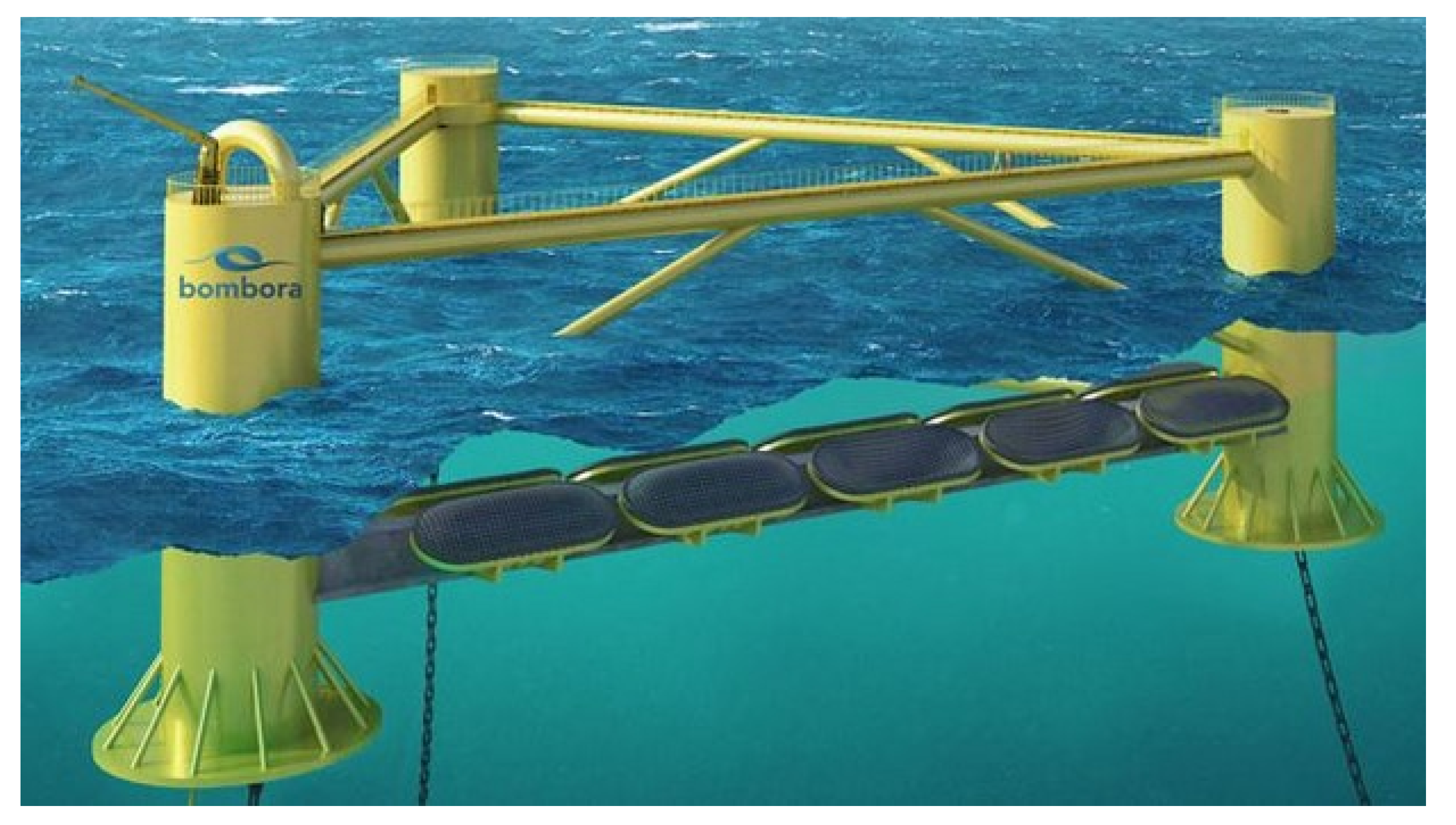
  80. mWave. Available online: https://bomborawave.com/mwave/ (accessed on 14 July 2021).
  81. Algie, C.; Fleming, A.; Ryan, S. Experimental and Numerical Modelling of the Bombora Wave Energy Converter. In Proceedings of the 3rd Asian Wave and Tidal Energy Conference (AWTEC 2016), Singapore, 25–27 October 2016. [Google Scholar]
  82. Algie, C.; Ryan, S.; Fleming, A. Predicted power performance of a submerged membrane pressure-differential wave energy converter. Int. J. Mar. Energy 2017, 20, 125–134. [Google Scholar] [CrossRef]
  83. Farley, F.J.M.; Rainey, R.C.T.; Chaplin, J.R. Rubber tubes in the sea. Philos. T. R. Soc. A 2012, 370, 381–402. [Google Scholar] [CrossRef]
  84. Mei, C.C. Nonlinear resonance in Anaconda. J. Fluid Mech. 2014, 750, 507–517. [Google Scholar] [CrossRef]
  85. Heller, V.; Chaplin, J.R.; Farley, F.J.M.; Hann, M.R.; Hearn, G.E. Physical model tests of the anaconda wave energy converter. In Proceedings of the 1st IAHR European Congress, Edinburgk, UK, 4–6 May 2010. [Google Scholar]
  86. Chaplin, J.R.; Heller, V.; Farley, F.J.M.; Hearn, G.E.; Rainey, R.C.T. Laboratory testing the Anaconda. Philos. T. R. Soc. A 2012, 370, 403–424. [Google Scholar] [CrossRef] [PubMed]
  87. Smith, W.R. Wave-structure interactions for the distensible tube wave energy converter. Proc. R. Soc. A 2016, 472, 20160160. [Google Scholar] [CrossRef] [Green Version]
  88. Anaconda Left Languishing by Wave Energy Scotland. Available online: https://www.checkmateukseaenergy.com/anaconda-left-languishing-by-wave-energy-scotland/ (accessed on 15 July 2021).
  89. Jean, P.; Wattez, A.; Ardoise, G.; Melis, C.; Van Kessel, R.; Fourmon, A.; Barrabino, E.; Heemskerk, J.; Queau, J.P. Standing wave tube electro active polymer wave energy converter. In Proceedings of the SPIE 8340, Electroactive Polymer Actuators and Devices (EAPAD), San Diego, CA, USA, 12–15 March 2012; p. 83400C. [Google Scholar]
  90. Babarit, A.; Singh, J.; Melis, C.; Wattez, A.; Jean, P. A linear numerical model for analysing the hydroelastic response of a flexible electroactive wave energy converter. J. Fluid Struct. 2017, 74, 356–384. [Google Scholar] [CrossRef] [Green Version]
  91. Ancellin, M.; Dong, M.; Jean, P.; Dias, F. Far-Field Maximal Power Absorption of a Bulging Cylindrical Wave Energy Converter. Energies 2020, 13, 5499. [Google Scholar] [CrossRef]
  92. Alam, M.-R. Nonlinear analysis of an actuated seafloor-mounted carpet for a high-performance wave energy extraction. Proc. R. Soc. A 2012, 468, 3153–3171. [Google Scholar] [CrossRef]
  93. Lehmann, M.; Elandt, R.; Pham, H.; Ghorbani, R.; Shakeri, M.; Alam, M.-R. An artificial seabed carpet for multidirectional and broadband wave energy extraction: Theory and Experiment. In Proceedings of the 10th European Wave & Tidal Energy Conference, EWTEC2013, Aalborg, Denmark, 2–5 September 2013. [Google Scholar]
  94. Lehmann, M.; Elandt, R.; Shakeri, M.; Alam, R. TheWave Carpet: Development of a Submerged Pressure DifferentialWave Energy Converter. In Proceedings of the 30th Symposium on Naval Hydrodynamics, Hobart, Tasmania, Australia, 2–7 November 2014. [Google Scholar]
  95. DOE Announces $24.9 Million Funding Selections to Advance Hydropower and Water Technologies. Available online: https://www.energy.gov/articles/doe-announces-249-million-funding-selections-advance-hydropower-and-water-technologies (accessed on 15 July 2021).
  96. Greaves, D.; Hann, M.; Kurniawan, A.; Chaplin, J.; Farley, F. The Hydrodynamics of Air-Filled Bags for Wave Energy Conversion. In Proceedings of the International Conference on Offshore Renewable Energy, Glasgow, UK, 12–14 September 2016. [Google Scholar]
  97. Kurniawan, A.; Chaplin, J.R.; Greaves, D.M.; Hann, M. Wave energy absortption by a floating air bag. J. Fluid Mech. 2017, 812, 294–320. [Google Scholar] [CrossRef] [Green Version]
  98. Michele, S.; Buriani, F.; Renzi, E.; van Rooij, M.; Jayawardhana, B.; Vakis, A.I. Wave Energy Extraction by Flexible Floaters. Energies 2020, 13, 6167. [Google Scholar] [CrossRef]
Figure 1. Mutriku harbour during the construction of the outer breakwater. Copyright 2010 Gari Araolaza, licensed under a Creative Commons Attribution (CC BY 2.0) license. Source: https://www.flickr.com/photos/garaolaza/4969812077 (accessed on 11 September 2021).
Energies 14 06537 g001
Figure 2. Chamber construction plan of the Mutriku power plant. Units are in metres. Image taken from Ref. [15] “Garrido, A.J.; Otaola, E.; Garrido I.; Lekube, J.; Maseda, F.J.; Liria, P.; Mader, J. Mathematical Modeling of Oscillating Water Columns Wave-Structure Interaction in Ocean Energy Plants. Math. Probl. Eng. 2015, 727982”. Copyright 2015 Author(s), licensed under a Creative Commons Attribution (CC BY 4.0) license.
Energies 14 06537 g002
Figure 4. OBREC prototype at the port of Naples. (a) Breakwater installation, (b) 3D scheme, (c) Functioning mechanism. Image taken from Ref. [31] “Iuppa, C.; Contestabile, P.; Cavallaro, L.; Foti, E.; Vicinanza, D. Hydraulic Performance of an Innovative Breakwater for Overtopping Wave Energy Conversion. Sustainability 2016 8(12), 1226.”. Copyright 2016 Author(s), licensed under a Creative Commons Attribution (CC BY 4.0) license.
Energies 14 06537 g004
Figure 5. WAB-type WEC operating in Pecem. Image taken from Ref. [32] “Cascajo, R.; García, E.; Quiles, E.; Correcher, A.; Morant, F. Integration of Marine Wave Energy Converters into Seaports: A Case Study in the Port of Valencia. Energies 2019, 12, 787.” Copyright 2019 Author(s), licensed under a Creative Commons Attribution (CC BY 4.0) license.
Energies 14 06537 g005
Figure 6. System of multi-resonant gates, after [35]. (Left) panel: Plan view. (Right) panel: Vertical section. Each gate has width a , the whole system is in a channel of width b and depth h . Image taken from Loughborough University Research Publications. Copyright 2019 Author(s), licensed under a Creative Commons Attribution (CC BY 4.0) license.
Energies 14 06537 g006
Figure 7. Poseidon hybrid wind–wave energy platform, developed by Floating Power Plant. Image taken from Ref. [44] “McTiernan, K.L.; Sharman, K.T. Review of Hybrid Offshore Wind and Wave Energy Systems. J. Phys. Conf. Ser. 2020, 1452, 012016.” Copyright 2020 Author(s), licensed under a Creative Commons Attribution (CC BY 3.0) license.
Energies 14 06537 g007
Figure 8. Artist’s sketch of the W2Power hybrid wind–wave system. Image taken from Ref. [44] “McTiernan, K.L.; Sharman, K.T. Review of Hybrid Offshore Wind and Wave Energy Systems. J. Phys. Conf. Ser. 2020, 1452, 012016.” Copyright 2020 Author(s), licensed under a Creative Commons Attribution (CC BY 3.0) license.
Energies 14 06537 g008
Figure 9. Schematic of the hybrid OWC investigated by [49]. The OWC chamber is installed on a monopile. A skirt of height h s is connected to the chamber to maximise power extraction. Image taken from Loughborough University Research Publications. Copyright 2019 Author(s), licensed under a Creative Commons Attribution (CC BY 4.0) license.
Energies 14 06537 g009
Figure 10. Behaviour of the Capture Factor in monochromatic seas, C F , and in irregular seas (JONSWAP), C F ζ , for an OWC mounted on a wind turbine foundation, after [49]. ω is the frequency of the monochromatic wave, ω P is the peak frequency of the spectrum, h is the water depth and g the acceleration due to gravity. Image taken from Loughborough University Research Publications. Copyright 2019 Author(s), licensed under a Creative Commons Attribution (CC BY 4.0) license.
Energies 14 06537 g010
Figure 11. Schematic of the EFHAS wave energy converter. Image taken from Ref. [64] “Kiran, M. R.; Farrok, O.; Abdullah-Al-Mamun, M.; Islam, M. R.; Xu, W. Progress in Piezoelectric Material Based Oceanic Wave Energy Conversion Technology, IEEE Access 2020, 8, 146428–146449”. Copyright 2020 Author(s), licensed under a Creative Commons Attribution (CC BY 4.0) license.
Energies 14 06537 g011
Figure 12. Geometry of the PWEC device modelled by [62]. The device is made by a bimorph flexible plate hinged at both ends. It has length L and submergence d. The water depth is denoted by h.
Energies 14 06537 g012
Figure 13. Power output for a flexible plate PWEC with respect to the period of the incident waves, after [62]. The plate is 20 m long, the submergence is 2 m, the water depth is 10 m, the incident wave amplitude is 1 m.
Energies 14 06537 g013
Figure 14. Artist’s sketch of Carnegie’s Desalination Pilot Plant. Image taken from Ref. [69] “Franzitta, V.; Curto, D.; Milone, D.; Viola, A. The Desalination Process Driven by Wave Energy: A Challenge for the Future. Energies 2016, 9, 1032”. Copyright 2020 Author(s), licensed under a Creative Commons Attribution (CC BY 4.0) license.
Energies 14 06537 g014
Figure 15. Artist’s sketch of the mWave device designed by Bombora. Reproduced with permission from [80], Bombora, 2021.
Energies 14 06537 g015
Figure 17. Side view of the flexible floater WEC, with the PTO mechanisms located at points x i , i = 1 , , M .
Energies 14 06537 g017
Figure 18. Behaviour of the Capture Factor versus frequency and PTO-Coefficient. (a) Flexible plate, stiffness factor E I = 6.9 × 10 3 kg m3s−2; (b) rigid plate.
Energies 14 06537 g018
Figure 19. Laboratory demonstration of the flexible floater (red silicone sheet inside the tank) connected to the MP2PTO system at the University of Groningen.
Energies 14 06537 g019
Table 1. Synopsis of the technologies for niche application discussed in this paper. In the case of hybrid devices, the performance indicators refer only to the wave energy component. Legend: OTD = overtopping device, OWC = oscillating water column, WAB = wave activated body, DM = deformable membrane, BW = bulge wave, EAP = electro active polymers, FB = floater blanket, PZ = piezoelectric, P = power, E = efficiency, n/a = not available.
NameCountryTypeWECStagePerformanceIndicator
MutrikuESPBreakwaterOWCOperational296 kW (P)
REWEC3ITABreakwaterOWCOperational26% (E)
OBRECITABreakwaterOTDOperational2.5 kW (P)
GatesUKBreakwaterWABConceptual0.7 ( C F )
PoseidonDENHybridWABSea trials30 kW (P)
W2PowerNORHybridWABLab testsn/a
Hybrid OWCUKHybridOWCLab tests0.4 ( C F )
inSPIREAUSHybridDMConceptual4 MW (P)
Power BuoyITAOffshoreWABOperationaln/a
ISWECITAOffshoreWABOperational50 kW (P)
Blue StarUKOffshoreWABLab testsn/a
EFHASJAPOffshorePELab tests40 mW m 2 (P)
PWECUKOffshorePEConceptual4 kW m (P)
DPPAUSDesalinationWABOperationaln/a
OdyséeCANDesalinationWABDemonstrationn/a
SarosUSADesalinationWABDemonstrationn/a
CETOAUSMicrogridWABOperational1 MW (P)
UniWave200AUSMicrogridOWCDemonstration200 kW (P)
CcellUKAquacultureWABLab testsn/a
AWS-IIIUKFlexibleDMSea trials2.4 MW (P)
mWaveAUS-UKFlexibleDMSea trials1.5 MW (P)
AnacondaUKFlexibleBWLab tests1.5 ( C F )
S3FRAFlexibleEAPLab testsn/a
Wave CarpetUSAFlexibleDMLab tests45 kW (P)
Air bagUKFlexibleDMLab tests0.9 m (W)
FloaterUKFlexibleFBLab tests0.26 ( C F )
Publisher’s Note: MDPI stays neutral with regard to jurisdictional claims in published maps and institutional affiliations.

