Review

Heat Transfer Augmentation through Different Jet Impingement Techniques: A State-of-the-Art Review

1
Mechanical Engineering Department, Capital University of Science & Technology, Islamabad 44000, Pakistan
2
Department of Mechanical Engineering, Air University Islamabad, Aerospace and Aviation Campus, Kamra 43750, Pakistan
3
Institute of Environmental Engineering and Building Installations, Poznan University of Technology, Pl. M. Sklodowskiej-Curie 5, 60-965 Poznan, Poland
4
Faculty of Environmental Engineering, Wroclaw University of Science and Technology, 50-370 Wroclaw, Poland
*
Authors to whom correspondence should be addressed.
Both the authors contributed equally to this work.
Energies 2021, 14(20), 6458; https://doi.org/10.3390/en14206458
Submission received: 15 September 2021 / Revised: 1 October 2021 / Accepted: 4 October 2021 / Published: 9 October 2021

Abstract

:
Jet impingement is considered to be an effective technique to enhance the heat transfer rate, and it finds many applications in the scientific and industrial horizons. The objective of this paper is to summarize heat transfer enhancement through different jet impingement methods and provide a platform for identifying the scope for future work. This study reviews various experimental and numerical studies of jet impingement methods for thermal-hydraulic improvement of heat transfer surfaces. The jet impingement methods considered in the present work include shapes of the target surface, the jet/nozzle–target surface distance, extended jet holes, nanofluids, and the use of phase change materials (PCMs). The present work also includes both single-jet and multiple-jet impingement studies for different industrial applications.

1. Introduction

The efficient and rapid methods of extracting excess thermal energy from target surfaces in different applications use both active and passive cooling techniques. The active cooling technique requires an external energy source, and in this regard, Zhou et al. [1] and Hackenhaar et al. [2] performed studies during which the active cooling technique was used, while the passive cooling technique uses conduction and radiation along with free convection as the main processes of heat removal. The passive cooling technique was used by Grubišić-Čabo et al. [3] and Zu et al. [4] during their investigation to achieve higher heat transfer rates. In high-temperature applications, the advantage of not using any external energy source in the passive cooling technique is often eclipsed by its poor heat transfer rate, while the active cooling technique, despite power consumption, demonstrates better heat transfer performance. In the active cooling technique, the jet impingement method provides an effective way for heat transfer enhancement because it disrupts the thermal boundary layer at the stagnation point on the impinged target surface. It has a wide range of applications in the field of engineering due to its significantly higher heat transfer performance among single-phase heat transfer arrangements. Its major application areas include cooling of electronic systems, turbine blades, solar systems, aerospace technology, hot metals, plastics sheets, drying of paper and fabric. The cooling of electronic systems has been studied by Maghrabie et al. [5] and Wiriyasart and Naphon [6], and the turbine blades application was covered by Ali and Janajreh [7] and Fawzy et al. [8] for jet impingement. The jet impingement application in solar systems was presented by Matheswaran et al. [9] and Awad et al. [10], and the aerospace technology application of impinging jets was investigated by Lim et al. [11] and Huang et al. [12]. The cooling of hot metals, plastics sheets, the drying of paper, fabric using jet impingement was studied by Chen et al. [13], Alkhudhiri et al. [14], Turkan et al. [15], and Wae-hayee et al. [16]. Heat transfer through jet impingement has been the focus of numerous experimental and numerical studies in the past. Initially, the emphasis was on establishing the fundamentals of jet impingement through various experimental studies, including parametric investigation of fluid flow and heat transfer mechanisms. The interest in the computational study of impinging jets has grown with rapid advancement in numerical algorithms and computational resources. The progress in the computational modeling of impinging jets and their applications was reported by Pulat et al. [17], Dewan et al. [18], and Dutta et al. [19].
It is important to understand the flow characteristics of impinging jets and their impact on heat transfer. The fluid flow characteristics strongly affect the heat transfer phenomenon in jet impingement. The flow structure of a single jet can be divided into three distinct regions: (a) free jet region, (b) stagnation region, and (c) wall jet region (see Figure 1). The free jet region starts from the nozzle and is far away from the target surface, thus acting as a free jet. The entrainment of mass, momentum, and energy takes place due to the shear-driven interaction of the jet periphery and surroundings in this region. The free jet can be subdivided into (i) a potential core, (ii) a developing zone, and (iii) a fully developed zone (see Figure 1). In the potential core zone, the jet average velocity is equal to the nozzle exit velocity. The jet core region length is measured from a point from the nozzle inlet to the point where the jet average velocity is around 95% of the nozzle exit velocity. The jet velocity decreases rapidly after the potential core, as presented by Jambunathan et al. [20]. This makes the jet plate/nozzle–target surface spacing an important parameter that affects the rate of heat transfer. After the potential core, the developing region exists where the decay of the axial velocity profile occurs due to large shear stresses at the jet periphery. Subsequently, the effects of shear stresses start to penetrate inside the core of the jet. A fully developed profile is obtained after the shear effects reach the core of the jet. In the fully developed region, at the centerline of the jet, the axial velocity component is the maximum while the radial velocity component is the minimum. The region where the jet strikes the target surface is termed the “stagnation region”. In the stagnation region, static pressure rises due to diminishing axial velocity. The region hereafter is called the wall jet region, where bulk fluid is directed radially outward. It is pertinent to mention that the maximum heat transfer takes place at the stagnation point (with the exception of a small separation distance) and a reduction in heat transfer rates occurs radially. The heat transfer between the impinging jet and the target surface can be affected by various factors, such as nozzle geometry, velocity profile, jet exit velocity, jet and target surface spacing, and turbulence level.
Although a considerable number of review papers are available on heat transfer through jet impingement, most of those are confined to a particular jet impingement technique or application. Jambunathan et al. [20] reviewed the data for a single circular jet impingement. A comprehensive review of jet impingement boiling to identify strengths and weaknesses and the scope for future work was conducted by Viskanta [21]. Different flow characteristics for single and multiple jets and the heat transfer performance of turbine systems were reviewed by Han and Goldstein [22]. The liquid jet impingement technique was critically reviewed for studying the heat transfer performance of discrete heated electronic modules by Patel and Hotta [23]. Heat transfer enhancement by synthetic jet impingement was reviewed by Krishan et al. [24]. Mohammadpour and Lee [25] reviewed the effects of nanoparticles on jet impingement heat transfer. For a combustor liner, jet impingement cooling was reviewed by Xie et al. [26]. Other recent reviews on jet impingement cooling include Chirade et al. [27], Qiu et al. [28], Marazani et al. [29], Darwish et al. [30], and Agrawal [31].
The current paper summarizes the hydrodynamic behavior and heat transfer augmentation of the target surface using different jet impingement methods by analyzing the various parameters affecting the heat transfer rate. This review paper also includes combinations of multiple jet impingement techniques that have been used to achieve improved heat transfer performance. First, the geometrical parameters of the target surface and jet–target surface spacing are explored. Afterward, different jet excitation methods are reviewed in detail. In the end, the roles of nanofluids and PCMs in jet impingements are reviewed comprehensively. The majority of the published work reviewed in this paper is from the last 3 years. The layout of the current study consists of a review of (1) the roles of shape variations of the target surface and the spacing between the jet and the target surface, (2) heat transfer enhancement by various exciting jets both actively and passively, and (3) using nanofluids (nanoparticles or nano-encapsulated PCMs) to enhance the thermal properties of base fluids to improve the heat transfer performance of the target plate.

2. Jet Impingement Methods

The wide range of industrial and domestic applications and the fundamental importance of jet impingement have made it an area of interest for many researchers. Jet impingement methods are used for achieving high rates of heat transfer. The rate of heat transfer due to an impinging jet is a function of several parameters, such as the shape of the target surface, the distance between jet plate/nozzle and target surface, jet excitation, the use of nanofluids, and PCMs and jet temperature dissipation. Some of the important dimensionless geometrical parameters that are used in jet impingement methods while achieving improved heat transfer performance are listed in Table 1. However, later, some of the other important parameters related to nozzle design, jet injection conditions, target surface design, and fluid properties will also be systematically introduced. The most recently published numerical and experimental results that consider the impact of different design parameters of impinging jets on the target plates are reviewed in this paper.

2.1. Target Surface Shape and Spacing between Jet Plate/Nozzle and Target Surface

Improvement in the design of jet impingement cooling systems compelled researchers to study various fundamental parameters that could affect heat transfer performance. In this regard, several variations in the shape of the jet impinging target surface and the distance between jet plate/nozzle and target surface to enhance the heat transfer rate can be found in the literature. In this regard, an experimental and numerical study was performed by Choi et al. [32] to study heat transfer augmentation for the internal cooling of turbine blades by using angled ribs and dimples. The Reynolds number, which was based on the channel hydraulic diameter, ranged from 30,000 to 50,000 for the study. The design of 2 and 4 channel aspect ratios was selected for stimulation of the internal coolant passage of the gas turbine blade. A rib pitch of 6 mm, rib angle of 6°, dimple diameter of 6 mm, and dimple center-to-center distance of 7.2 mm were used. An increase in the heat transfer coefficient and an increase in the pressure drop in an acceptable range were observed by placing dimples between the ribs (rib–dimple compound case) as compared to the rib-only and the dimple-only configuration. It is pertinent to mention that heat transfer improvement through different jet impingement techniques is usually accompanied by a significant increase in pressure drop of the flow across the target plate because of enhanced fluid–surface interactions. Therefore, it is always desirable to have such a system that yields the maximum heat transfer enhancement at a minimum hydraulic loss penalty. Therefore, to measure the overall performance of a system, simultaneous considerations of heat transfer and the friction factor are imperative. In this context, the performance enhancement criterion (PEC) was first proposed by Webb and Eckert [33] as a Stanton number–friction factor ratio, defined by ( S t / S t o ) / ( f / f o ) 1 / 3 . PEC < 1 means that the heat transfer performance is less than the required pumping power and the solution provided is not feasible. PEC = 1 indicates that heat transfer is equal to pumping power and the solution provided has no impact on the overall performance of the system. PEC > 1 specifies that the enhancement of the heat transfer rate exceeds the overall required pumping power and therefore the performance of the system has improved. Moreover, for a feasible heat transfer augmentation solution, the PEC must be sufficiently larger than 1. An exhaustive review of the performance enhancement criterion, as an effective tool for measuring heat and fluid flow characteristics, was provided by Yilmaz et al. [34]. The PEC has also been indexed in several heat transfer applications [35,36,37,38]. In the context of heat transfer through jet impingement, the thermal-hydraulic performance evaluation was also carried out using the PEC by Choi et al. [32]. However, the PEC was based on the Nusselt number–friction factor ratio, as presented in Equation (1). It must also be noted that the PEC is a function of the Reynolds number because both the Nusselt number and friction factors are functions of the Reynolds number; therefore, the PEC may vary for different Reynolds numbers.
PEC = N u N u 0 ( f f 0 ) 1 3
In Equation (1), Nu represents the Nusselt number of the target surface of the enhanced case and Nu0 refers to the Nusselt number of the reference case. Similarly, f is the friction factor for the impinging flow over the target plate of the enhanced case, whereas f0 indicates the friction factor of the smooth surface of the reference case. Recently, the combination of porous media and jet impingement has drawn significant attention using open-cell metal foams for achieving higher cooling rates. In this regard, Feng et al. [39] performed an experimental and numerical study to investigate the cooling performance of finned metal foam heat sinks under impinging jets. Four plate fins of 2 mm thickness and aluminum foams having 96.3% porosity and 8 pores per inch (PPI) were used during the experiments. It was observed from the results that at a given flow rate with an increase in foam height, the heat transfer of the metal foam heat sink decreases, while that of the finned metal foam heat sink first increases and then decreases slightly. A heat transfer enhancement rate of 1.5–2.8 times was achieved by using finned metal foams instead of metal foams. It was also observed that the bonding material with a large height causes an increase in heat transfer because of the increase in the effective thickness of the fins. In another study, Feng et al. [40] conducted a numerical investigation of the thermal performance of finned open-cell aluminum foam having a fixed porosity of 0.9118 and 5 pores per inch (PPI) for an imaging jet application. It was noted from the results that 26% lower thermal resistance was recorded for the finned aluminum heat sink as compared to the plate-fin heat sink at a given pumping power. Andreozzi et al. [41] performed a numerical investigation to study the thermal performance of finned and bare metal foams for variation of geometrical parameters under air jet impingement. The range of parameters used were D/W (impinging flow section diameter–heated plate side ratio) = 0.25–1.0; foam porosity = 0.88–0.97; and PPI = 5–40. A higher heat transfer coefficient and pressure drop were achieved for finned metal foam as compared to bare metal foam for the diameter of the impinged jet equal to the heated plate. A numerical study was performed by Bianco et al. [42] to improve the thermal and hydraulic performance of finned and bare heat sinks under a circular impinging jet. The heat dissipation rate was observed to be enhanced by 3.3 to 3.5 times for the finned metal foam heat sink in comparison to the metal foam heat sink for the same pumping power. Wan et al. [43] performed a numerical study to observe heat transfer characteristics by impinging an array of jets over a flat plate and a roughened plate. The roughened plate consisted of inline and staggered square pin-fin arrangements. An experimental setup consisting of a flat plate and a roughened plate was also prepared to validate the numerical model. The Reynolds number (based on the jet diameter) range during this study was from 15,000 to 35,000. It was observed that heat transfer augmentation can be achieved through both inline and staggered roughened pin-fin arrangements. A 34.5% higher overall heat transfer rate was achieved by using an inline roughened pin-fin plate as compared to the flat plate. Improvement in heat transfer enhancement for a microchannel heat sink with jet impinging (MIJ) by introducing dimples into the target surface was studied by Huang et al. [44]. A comparative numerical study was performed between MIJs with concave, convex, and mixed dimple structures and MIJs without dimples. The results showed that in the case of convex dimples, the cooling performance exhibited by MIJs was the best. The next best cooling performance was shown by MIJs without dimples, followed by MIJs with mixed dimples and then with concave dimples. It was also observed that a decrease in flow resistance is possible with the application of convex dimples in MIJs. The highest pressure drop was observed in MIJs without dimples, followed by MIJs with mixed, concave, and convex dimples. It was summarized that MIJs with convex dimples can improve heat transfer and fluid flow performance more as compared to other structures.
A numerical study was performed by Jing et al. [45] to investigate the performance of jet impingement cooling on flat and non-flat target surfaces (concave and V shapes) (see Figure 2). The Reynolds number (based on the jet diameter) range for the study was 10,000–50,000. Additional surface arrangements of triangular ribs and dimple/protrusions were also included on target surfaces. More complex flow patterns were observed for non-flat target surfaces as compared to flat targets. An improvement in both local and overall heat transfer was experienced by adopting dimples/protrusions. In flat channels, an increase in the average Nu/Nu0 was observed for a larger Reynolds number and the largest Nu/Nu0 was observed for the sparse arrangement. However, for the non-flat targets, protrusions were observed to show significant advantages over dimples as far as the performance of heat transfer was concerned. Furthermore, a larger f/f0 was produced by protrusions as compared to dimples for flat targets, and in the case of concave/V-shape targets, a low f/f0 was observed. The quantity of heat flux was observed to be less affected by target surface shapes; however, the role of the target arrangement and Reynolds number was more significant. The study had a significant impact on the thermal design of turbine blades and electronic equipment.
An experimental study was performed by Nagesha et al. [46] to analyze the heat transfer characteristics of jet impingement on a heated surface with multi-protrusions and V grooves. The Reynolds number (based on the jet diameter) range used during the study was from 10,000 to 27,500. It was observed from the results that heat transfer is enhanced more by well-separated multi-protrusions as compared to V grooves with close spacing. A numerical investigation was conducted by Xu et al. [47] for studying the flow fields under jet impingement over a concave surface. The study was performed for swirling and non-swirling jets at a Reynolds number (based on the jet diameter) of 16,000 and jet–target surface spacing H/D = 2. The jets were injected from four spiral and straight grooves. Heat transfer was improved by 5–10%, with a hole having spiral grooves of 45°. Figure 3a,b presents contour plots of the instantaneous velocity of non-swirling (0°) and swirling (45°) jets. It can be observed that the swirling jet experienced a larger obstruction as compared to the non-swirling jet due to the presence of a spiral channel. In the 45° swirling jet, most of the jet was located in the central region of the nozzle, which resulted in a large axial velocity of the potential flow core. It was also observed that the swirling jet had a larger tangential velocity due to the swirl effect and a better capability to entrain the surrounding low-speed air flow. A skirt-type green region with a larger diffusion area was formed at the periphery of the potential flow due to the mixed air flow. In the non-swirling jet, a taper-foot green region with a low diffusion area was formed because the injected velocity and the nozzle central region velocity had a small difference due to the wall boundary layer and had a longer potential flow. The rebound from the concave target surface after jet impact was observed to be smaller in the case of swirling as compared to non-swirling jets, which meant that swirl flow struggled to escape from the target surface. This resulted in the improved cooling effect on the target surface due to uniform heat transfer. Figure 3c shows the Nu number ratio (Nu/Nust), where Nu is the local Nusselt number and Nust is the local Nusselt number at the stagnation point, on the target surface. The swirling action of the 45° spiral hole groove caused the elimination of the difference in heat transfer, which resulted by the decay in speed of the boundary between spiral and central circular holes. This difference in heat transfer was eliminated due to the increased dispersion of the jet medium by the spiral hole. Furthermore, Table 2 provides a summary of different shapes of the target surfaces that have been used in the recent literature for heat transfer enhancement through jet impingement.
Tepe et al. [58] performed a numerical study to investigate cooling performance by using extended jet holes to impinge turbines blade having the target surface as a flat plate with ribs. The Reynolds number (based on the jet diameter) range was from 15,000 to 45,000 during the study. The average Nu was decreased by placing ribs on the target surface as compared to the target surface with no ribs. However, the distribution of Nu was more uniform along the surface in the presence of ribs. In another work, Tepe et al. [59] performed an experimental and numerical investigation using extended jet holes to study the cooling performance by impinging a jet on a rib-roughened surface (see Figure 4a). The ratio of rib height to jet diameter (Hr/Dj) was considered as 0.42 for the experimental study, while for the numerical investigation, Hr/Dj = 0, 0.25, 0.42, and 0.58 were used. Furthermore, the ratio of nozzle to target surface spacing (Gj/Dj) was 1, 2, 3, 4, 5, and 6; the streamwise distance X/Dj was 5–30; and the Reynolds number (based on the jet diameter) range was from 16,250 to 32,501. It was observed from the results that by using extended jet holes, the average Nu is enhanced by 40.32% when a rib-roughened target surface is used. A relatively low rib height (Hr/Dj = 0.25) was found to be more effective in heat transfer enhancement. At a high Reynolds number of 32,500, the highest Nu values were obtained for Gj/Dj = 3.0, whereas at a low Reynolds number of 27,100 or less, the highest values of Nu were obtained at Gj/Dj = 2.0 or less. The contour plots for the local Nu for various values of Gj/Dj at rib height Hr/Dj = 0.42 and Reynolds number Re = 32,500 are presented for both experimental and numerical studies (see Figure 4c). It can be observed that the extension of jet holes (reducing Gj/Dj) caused an increase in the local Nu value. It was also observed that the last impingement region did not experience significant heat transfer for any Gj/Dj value considered in the study. The highest Nu values in the mid-section of the target surfaces resulted from the influence of cross-flow, which increased in the streamwise direction; however, its effect was found to weaken after X/Dj > 15. It was observed from the performance enhancement criterion that the use of extended jet holes is a feasible method for jet impingement cooling, particularly for a nozzle–target surface spacing of 3.0 or less. The highest performance enhancement criterion of 1.25 was achieved at the nozzle–target plate spacing of 2.0.
In a recently published research, Tong et al. [60] performed a numerical investigation to study the heat transfer due to impingement on the inner casing of a high-pressure turbine. The numerical study was conducted for various target surface shapes, such as smooth, round, and square pin fin and cambered rib (see Figure 5). It was observed from the results that the roughness introduced into the system improves the heat transfer performance of the system. Among all the surface configurations, the cambered rib configuration produced the best heat transfer characteristics. In comparison to the smooth surface, all configurations were observed to produce the best cooling effect, for example, a 20 K decrease in temperature of the turbine’s inner casing and a 62.6% increase in the average Nu were achieved by using a cambered rib surface configuration. The flow structure analysis illustrated that an effective reduction in jet interaction and cross-flow is caused by a cambered rib surface configuration. This reduction in cross-flow and jet interaction further causes a turbulent mixing and impingement cooling effect. An experimental investigation was performed by Singh et al. [61] to study the heat transfer characteristics of a solar air heater due to circular jet impingement. For the jets of impinging air to provide plate perforation of 1.4–0.48%, a wavy plate that was corrugated and consisted of circular holes (each of 7.66 mm diameter) on the crest part of the wave was used. Air was circulated through a double pass, and for provision of thermal backup and enhancement of heat transfer, two designs, i.e., Design-I and Design-II, with and without porous media, respectively, were used. A porosity of 98%, a mass flow rate of 0.4 kg/s, and plate perforation of 0.48% were recommended for the operation of the solar air heater to achieve the best thermal performance. Design-I produced a thermal efficiency of 94% (7.5% more than Design-II) and a thermos-hydraulic efficiency of 84% (19% more than Design-II). Maithani et al. [62] experimentally studied the thermal and friction characteristics of an absorber plate with protrusion of a hemispherical shape by jet impingement. To achieve larger turbulence, the hemispherical protrusions were placed exactly below the impinging jet holes. Analysis was performed by varying geometric parameters of the relative protrusion diameter–protrusion height ratio (dpr/epr), and a thermo-hydraulic parameter’s maximum value of 3.01 was achieved. An experimental and numerical study was performed by Hadipour et al. [63] to investigate the effect of a triangular guided rib (TGR) on thermal and flow characteristics of turbulent jet impingement on a concave surface. The asymmetric concave surface had curvature radii of 8 cm and 12 cm. To investigate the effect of the TGR, a triangular rib (equilateral) having each side of 12 mm was used in the stagnation region. The Reynolds numbers used during the study were 23,000, 35,000, and 50,000. It was observed from the results that a high average Nu is achieved using a TGR and a horse-shoe shape is created in the high-Nu region due to the TGR through the acceleration of the impinging jet. A numerical study was performed by Tepe [64] to investigate heat transfer performance over a semi-circular concave target surface by impinging a staggered array jet with a novel hole jet design (see Figure 6). The Reynolds number (based on the jet diameter) range during the study was varied from 5000 to 25,000, the spacing between confinement plate and target surface plate (H/d) was varied from 1.0 to 8.0, and the spacing between jet nozzle and target surface plate (G/d) was altered from 0.5 to 6.0. It was observed from the results that as the spacing between jet nozzle and target surface plate (G/d) was lowered, both local and average Nu increased and a highest heat transfer enhancement of 20.16% was obtained at G/d = 0.5 and H/d = 8.0. A PEC value of 1.1 was achieved for the case with G/d = 2.0 and H/d = 8.0, thus making it the most feasible design.
Lytle and Webb [65] performed an experimental study to investigate the thermal performance of an impinging air jet at a low nozzle–target plate distance. The nozzle–target plate distance was kept less than one nozzle diameter during the study. It was observed from the results that a substantial increase in heat transfer is achieved by reducing the gap between the nozzle and the target plate. This increase in heat transfer was achieved due to the accelerating fluid and high turbulence obtained by lowering the space between nozzle and target plate. An experimental study was performed by Lee et al. [66] to investigate the effect of the jet plate–target plate distance on heat transfer for an array of jet impingement directed at a flat target surface. The study was conducted for a Reynolds number range of 8000 to 50,000 and jet–target plate distances of 1.5 D, 3 D, 5 D, and 8 D. The local increase in Nu was observed in cross-flows by a smaller distance between jet and target plate and at a lower Reynolds number. This augmentation in the local Nu was caused by the vigorous nature of the interaction between impinging jets and an increase in the magnitude of mixing and turbulent transport. Jet impingement heat transfer was studied by Madhavan et al. [67] by using high-porosity metal foams between the jet plate and the target plate. High-porosity metal foams are used due to their high heat transfer rate. Experiments were conducted for a jet–target plate distance Z/Dj of 0.75, 2, and 4. The Reynolds number range used was from 3000 to 12,000. At a jet–target plate distance of 0.75 and with the base fully covered with metal foam, a heat transfer enhancement of 2.42 times was achieved at the cost of 1.67 times pressure drop. Tepe et al. [68] performed a numerical and experimental investigation for heat transfer enhancement by using extended jet holes. The jet plate–target plate distance Z/Dj of 6 and the nozzle–target plate distance Gj/Dj were varied for values of 1, 2, 3, 4, and 5. The Reynolds number range used during the study was between 16,250 and 32,500. It was observed from the experimental results that an increase in heat transfer and pressure drop is caused by the decrease in Gj/Dj. Investigation of the PEC ratio showed that the most feasible solution is achieved at a nozzle–target plate distance Gj/Dj = 2 for all values of the Reynolds number. The highest PEC ratio of 1.25 was obtained at the nozzle–target plate distance Gj/Dj = 2 at a Reynolds number of 32,500, thus making it the most feasible solution in extended jet hole design.
A nearly constant value of Nu was observed for the nozzle–target plate distance variation by Gao et al. [69] while studying the heat transfer performance of free surface jet impingement using molten salt during their experimental investigation. Ji et al. [70] performed an experimental investigation of high-velocity steam jet impingement on an ice surface to study its heat transfer performance. A steam temperature of 140 °C and a non-dimensional nozzle–ice surface distance range from 5 to 18 were used during the experimental investigation. It was observed from the results that the highest ice melting rate is achieved at a nozzle exit velocity of 40 m/s, and a nozzle–ice surface spacing under 12 was recommended. Numerical simulations were performed by Siddique et al. [71] to study secondary peaks on the Nu profile generated by impinging a water jet on the target surface. During the numerical study, the Reynolds number range was from 825 to 41,292, and the nozzle–target plate spacing (Z/d) was varied from ¼ to 4. The major cause behind the generation of the secondary peak in the Nu profile was observed to be the jet with high velocities achieved through reducing the nozzle–target plate spacing. Yadav and Saini [72] performed a numerical investigation using an absorber plate with jet impingement to study the thermal performance of solar air heaters. The numerical study was performed for a range of Reynolds number from 3500 to 17,500 and a system parameter range of the jet diameter ratio from 0.065 to 0.195 and the jet height ratio from 0 to 0.433. It was observed from the results that at a Reynolds number of 17,500 and a jet diameter ratio and jet height ratio of 0.0650 and 0.216, respectively, an enhanced maximum heat transfer of 7.58 was obtained at the cost of 9.01 times friction factor penalty. For the same values of jet diameter ratio and jet height ratio and a Reynolds number of 15,500, a maximum thermal-hydraulic performance parameter value of 3.66 was achieved.
An experimental and numerical study was conducted by Baghel et al. [73] to investigate the heat transfer characteristics of inclined jet impingement. During this study, the jet–target surface distance was kept constant (H/d = 4) and four different jet inclination angles (0°, 15°, 30°, and 45°) were used. The range of the Reynolds number for the experimental work was 17,541, 26,311, 35,081, and 438,521, and for numerical investigation, Reynolds numbers 17,541 and 26,311 were used. It was observed from the results that the peak Nu location shifts toward the compression side as the inclination angle increases but its magnitude remains almost unaffected. The location of the maximum Nu was observed to be insensitive to the Reynolds number. Pratap et al. [74] performed a numerical study to analyze the impact of impingement height, using nanofluids, on heat transfer performance through a circular confined jet. The non-dimensional jet–target plate spacing (H/D) ranged from 2 to 10. Other parameters for jet impingement were jet diameter = 2 mm and Reynolds number = 20,000. It was observed from the computational results that the value of Nu increases as the H/D ratio increases for both water and nanofluids. An experimental and numerical investigation was performed by Forster and Weigand [75] to study the heat transfer performance of jet array impingement over a turbine blade resembling a concave target surface. During this study, the jet–target plate separation (H/Djet) varied from 2.7 to 4.0 and the Reynolds number used was 30,000. It was observed from the results that at a low separation distance, the heat transfer is enhanced. A numerical investigation was performed by Alhajeri et al. [76] for a Reynolds number range from 15,000 to 45,000 and nozzle edge–target surface spacing H/D = 2, 4, 6, and 8 to investigate cooling performance for unconfined jet impingement with mist/steam uniformity effects. The results recorded that heat transfer is enhanced at H/D = 2, 4, and 6 with an accumulation of steam/mist around the edge. With the increase in the value of the Reynolds number, Nu decreases for all H/D values and the impact of Reynolds number is observed to be more significant as the value of H/D increases (see Figure 7). The effects of the shapes of jet nozzle and target surfaces are further summarized in Table 3.
Enhanced surface designs, including dimples, indentations, and ribs, increase the heat transfer performance of the surface by improving fluid–surface interactions through turbulence generation and a convective heat transfer rate. However, alongside heat transfer performance, hydraulic performance is also important. An increase in the friction factor is observed in all of the reported studies because of the induced interference in the flow by enhanced surfaces. In the reported literature, the effectiveness of different surfaces has been measured by performance enhancement criteria. It has also been observed that dimpled shapes as compared to other surface designs give a better thermal-hydraulic performance. Another method of achieving large turbulent mixing is by reducing the gap between jet plate/nozzle and target surface, thus achieving high heat transfer performance. The studies reported in this review show that when the jet plate/nozzle are brought closer to the target surface, through vigorous interaction of impinging jets, large turbulence is produced, thus giving an enhanced heat transfer rate. Therefore, it can be established that the acceleration of jets and enhanced surface–fluid interactions play an important role in achieving large turbulence and thus achieving high heat transfer performance. These observations highlight the importance of jet excitations in attaining high surface heat transfer rates. The use of jets excitations to intensify the heat transfer rate is studied in the next section.

2.2. Excited Jets

The quest for further improving the heat transfer performance of jet impingement cooling on a target surface made way for using passive and active excited jets. These excited jets have considerable implications for thermal system performance by improving jet turbulence and mixing characteristics. These excited jets have the potential to intensify impingement over a larger area of the target surface as compared to steady jets [89]. The heat transfer enhancement through jet excitation is achieved through passive and active jet excitement methods. No moving parts are involved in the intensification of heat transfer through the passive jet excitation method. The passive method involves swirling jets, sweeping jets, and annular jets for heat transfer enhancement.
In this regard, Xu et al. [90] performed a numerical study to analyze the effect of swirling jets achieved through threaded holes on the heat transfer performance of gas turbine blades. They used 45° threaded holes instead of circular holes to study the impact of swirling jet impingement on heat transfer. The jet inclination angle was varied from 45° to 90°, and the other parameters studied were jet–plate spacing (H/d) = 2, 4, and 6 and the Reynolds number range from 6000 to 24,000. It was observed from the results that the jet inclination angle and jet–plate spacing have a major effect on the location and size of vortices, while the Reynolds number is almost insensitive to them. A swirling impingement jet in an inclined position was more effective in terms of cooling performance as compared to circular impingement. An experimental investigation was performed by Wongcharee et al. [91] to study the impact of a swirling jet delivered through a twisted tetra-lobed nozzle on heat transfer augmentation (see Figure 8). For comparison, circular and tetra-lobed nozzles were also studied. The jet–target plate spacing (L/D) used was 3, 4, and 5; twist ratios (y/Dh) used were 2, 3, 4, and 5; and the Reynolds number range used was from 4000 to 28,000. It was observed from the results that the Nu value increases for all nozzle types used for increasing the Reynolds number and decreasing the jet–target spacing. The heat transfer performance was better for tetra-lobed and twisted tetra-lobed nozzles as compared to the circular nozzle at a given jet Reynolds number. The maximum Nu value was achieved through a twisted ratio of 4.0 for the twisted tetra-lobed nozzle. Heat transfer rates were enhanced by 27.7%, 25.0%, 21.6%, and 19.3% by using a twisted tetra-lobed nozzle with twisted ratios of 2.0, 3.0, 4.0, and 5.0, respectively, as compared to a circular nozzle (non-swirling jet). Ikhlaq et al. [92] numerically studied the impact of the weak swirling jet (S = 0.31) on a heated plate for heat transfer characteristics. The study was performed for jet–plate spacing (H/D) = 2, 4, and 6. It was observed from the results that at H/D = 2, the weakly swirling jet inflow condition suppresses heat transfer. A numerical investigation was performed by Debnath et al. [93] to study the comparison of the effect of swirling and non-swirling jet array impingement flow on heat transfer performance. The two conditions were swirling flow (S = 0.74) and non-swirling flow (S = 0), the jet–plate spacing (H/D) was kept constant at 2.0, and the Reynolds number used was 11,600. Two different array arrangements, i.e., staggered and inline, were used during the study. It was observed from the results that staggered arrangements show better performance at mixing and heat transfer. For the non-swirling jet condition, an accurate heat transfer prediction was made around the stagnation region, and for swirling jet impingement, it was predicted between neighboring jets.
Sapra and Chander [94] experimentally studied the effect of various operating and design parameters on impingement heat transfer performance in dual swirling burning with a tangential entry. The parameters studied were Reynolds number, equivalence ratio, and separation distance. It was observed from the results that geometrical design parameters have a reasonable effect on the intensity of swirl, thus causing a significant impact on the heat transfer performance of the burner. An experimental investigation was performed by Chang and Shen [95] to study the heat transfer characteristics of a swirling jet array from a nozzle plate with and without patterned grooves. Induction of a swirling jet in the nozzle was caused by twisted tape having 1–2 twist pitches. The Reynolds number range was from 1500 to 20,000, and the nozzle–target plate non-dimensional spacing was from 0.1 to 8. Nu correlations and local heat transfer properties due to groove impact were presented. It was observed from the results that heat transfer performance is improved with patterned grooves. Chang et al. [96] performed an experimental study of the heat transfer performance of swirling and non-swirling jets originating from an orifice plate with grooves. It was observed from the results that cross-flow effects (not favorable) are minimized by either grooves or swirling jets and heat transfer is augmented for small separation distances. A numerical investigation was performed by Fawzy et al. [97] in which swirl and impingement techniques for cooling turbine blades using multiple conical nozzles were combined to achieve optimal heat transfer performance. It was observed from the results that by increasing the Reynolds number value from 10,000 to 25,000, this compound cooling technique can achieve a 99.7% increase in heat transfer augmentation for a constant temperature ratio. For an increase in the temperature ratio from 0.65 to 0.95, an increase of 11% was observed in the overall Nu value at a constant Reynolds number. The results also demonstrated better heat transfer performance by the compound cooling technique as compared to impingement and swirl techniques separately. In another study by Fawzy et al. [98], the effect of the slot angle and slot area ratio was investigated for swirl cooling of gas turbine blades. Slot angles used during the study were 60°, 75°, 90°, and 105°, and slot area ratios were 1.0, 2.0, 3.0, and 4.0. When the slot area ratio was increased from 1.0 to 4.0, an increase of 23% and 30% in the thermal performance factor and the global Nu was achieved by this system for identical Reynolds number values. However, for an increase in the slot angle from 60° to 105°, a relatively small increase of 7.5% in the global Nu was achieved, whereas the thermal performance factor was enhanced by 29.8%.
Heat transfer and flow characteristics were experimentally studied by Park et al. [99] for sweeping jet impingement on a flat surface. The study was performed for four different Reynolds numbers (3600, 6400, 11,000 and 15,300) and three nozzle–target plate spacing (H/d) values (1.0, 2.0m and 3.0). Nu distribution divided the impinging heated wall into two zones, (i) a high Nu near the center zone and (ii) a lower Nu away from the central zone. Zhou et al. [100] performed an experimental investigation to study heat transfer enhancement for a sweeping impinging jet with narrow spacing. During the study, Reynolds number values used were 5000, 10,000, and 15,000, and the jet–wall spacing (H/d) was kept at 0.5, 1.0, 2.0, and 3.0. From the results, it was observed that the heat transfer performance of a sweeping jet system increases with increasing Reynolds number and decreases with decreasing jet–wall spacing. Around the stagnation zone, a maximum of 40% heat transfer enhancement was achieved by using a sweeping jet instead of a circular jet. An experimental study was performed by Wen et al. [101] to analyze the potential application of a master–slave fluidic oscillator used to produce sweeping jet impingement having adjustable spreading angles (see Figure 9). An increase in spreading angles of the jet from 0° to 100° was achieved by increasing the master flow rate (MFR) from 0 to 1. It was demonstrated that a novel design of sweeping jets and guides can be applied for different impingement targets and conditions for heat transfer enhancement. The heat transfer characteristics and flow behavior were experimentally studied by Kim et al. [102] for a sweeping jet generated through a fluidic oscillator (feedback-free) impinging on a flat surface. The study was performed for a Reynolds number range from 8000 to 32,000 and a jet–wall spacing of 3.0, 5.0, and 8.0. The results for the feedback-free sweeping jet case for different Reynolds number values and jet–wall spacings were compared with normal-feedback sweeping jets and square jets (see Figure 10). The heat transfer performance of the feedback-free sweeping jet was better than that of the normal-feedback sweeping jet and square jet for all values of the Reynolds number at a jet–wall spacing of 5.0 and lower. At a high jet-wall spacing of 8.0, the heat transfer performance of the square jet surpassed the normal-feedback sweeping jet and the feedback-free sweeping jet.
Heat transfer performance was numerically investigated by Afroz and Sharif [103] for a heated target surface by turbulent annular swirling jet impingement. Ansys Fluent software was used for computation, and swirling and non-swirling jet impingements were studied by using the k-ε realizable model. The parameters used during the study were a Reynolds number ranging from 5000 to 25,000, a swirl strength ranging from 0 to 0.77, a jet exit–target surface spacing ranging from 0.5 to 4.0, and an annular jet blockage ratio ranging from 0.4 to 0.6. It was confirmed from the results that when the spacing between the jet exit and the target surface is small, i.e., 0.5, the average Nu is enhanced by 8% for a certain combination of Reynolds number, swirl strength, and blockage ratio. However, when the spacing between the jet exit and target surface is large, average, and peak initially, Nu experiences a slight increment and then a linear increase with increasing swirl strength. Dutta and Chattopadhyay [104] performed a numerical study to investigate the flow and heat performance of turbulent swirling jet impingement on a heated target plate. The geometry of the annular jet was selected in such a manner that the mass and momentum efflux of both annular and circular jet exits (for the same inner jet diameter) remained the same for certain Reynolds numbers. An under-prediction of heat transfer characteristics was observed from the two-dimensional study. Furthermore, flow and heat transfer performance was compared for annular and circular jets. An experimental investigation was performed by Fenot et al. [105] to study the heat transfer performance of quasi-annular jet impingement, and a comparison was drawn among these jets and with a circular jet. During the study, mass flow was kept constant and the blockage ratio (Dint/D) parameter was varied. A major influence of the injection jet–target plate distance (H/D) on heat transfer was observed at H/D = 2 or lower values. Recirculation was observed downstream of injection due to the inner structure, which was dependent upon Dint/D and H/D. A major influence of both parameters Dint/D and H/D on heat transfer was recorded in the impingement region, and this impact was less effective in the wall jet region.
When moving parts are involved to intensify heat transfer in jet impingement, this technique is termed “active jet excitement.” It involves two types of jets for excitation, i.e., synthetic jet and pulsating jet. These synthetic and pulsating jets are produced by acoustic and mechanical actuators. Due to its huge weight, more power consumption requirements, and high maintenance needs, this method is less feasible for large-scale engineering applications and is used mainly for small-scale applications. Synthetic jets are jets having flow with oscillation in such a manner that the time-averaged velocity remains zero. In this regard, Huang et al. [106] performed an experimental and numerical investigation to study the heat transfer performance of a heat sink longitudinal fin from an electronic cooling system using the active jet excitation technique of synthetic jet impingement. The study was based on analyzing the effect of the amplitude and frequency of movement of the diaphragm and the jet–target surface spacing. A good match between computational and experimental work was recorded. For fin surfaces, a linear increase was observed in the average heat transfer coefficient against the operating frequency. The highest heat transfer performance of 650 W/m2-K was achieved for a 2700 Hz operating frequency for a double circular orifice. The impact of amplitude on the heat transfer coefficient resulted in a linear relationship, and the cooling performance was found to be rather insensitive to jet–target surface spacing. An experimental investigation was performed by Singh et al. [107] to study the heat transfer characteristics of impinging synthetic jet over a hot surface using various shapes of the orifice, such as circular, square, and rectangular. A maximum heat transfer coefficient that was 16.1 times greater for the current setup versus natural convection was achieved. Travnicek and Antosova [108] performed an experimental study to investigate the heat transfer performance of rectangular synthetic jet impingement on a wall. The synthetic jet was originating from a nozzle having an oscillating cross section. It was observed from the results that a maximum heat transfer performance is caused by a phase shift (maximum at a phase shift of 270°) between diaphragm and nozzle cycles. An experimental study was conducted by Singh et al. [109] to investigate the flow and heat transfer performance of synthetic jet impingement with multiple orifices. The shapes of the multiple-orifice synthetic jet used during the study were circular, rectangular, and square. The Reynolds number used during the experimental investigation was in the range of 1689 and 4670, and the dimensionless axial distance ranged from 1 to 25. It was recorded from the results that a 60% higher average Nu is observed for multiple-orifice jets in comparison to a single-orifice jet.
An experimental setup was arranged by Lyu et al. [110] to study the thermal performance of piston-driven synthetic jet impingement (see Figure 11). The range of operational frequencies used was from 5 Hz to 25 Hz, and the jet–target spacing (H/d) ranged from 2 to 14. It was observed from the results that during the working phenomenon of synthetic jet impingement driven by a piston, the friction heat generation and warm air suction cause a rapid increase in the air temperature at the initial stage. A maximum Nu of 72 was achieved for jet–target spacing = 4 and operational frequency = 5 Hz when the adiabatic wall temperature was used as a reference temperature while defining the convective heat transfer coefficient. Gil and Wilk [111] performed an experimental investigation to study heat transfer performance of synthetic jet impingement. In this setup, a special actuator comprising a loudspeaker and a Plexiglass cavity was used to create the synthetic jet (see Figure 12). The parameters under investigation for studying heat transfer performance were the supply and geometry of the synthetic jet actuator. The excitation frequency ranged from 5 to 600 Hz, the dimensionless stroke length range was 0.84–170.5, and the Reynolds number range used during the study was 3600–2950. The geometrical parameters that were varied in the actuator were orifice diameter, orifice thickness, and cavity depth. A maximum heat transfer enhancement was observed to be achieved at dimensionless stroke length = 4 and was caused by the increase in the strength of the vortex. In another experimental work, Gil et al. [112] investigated the effect of synthetic jet impingement for a constant Reynolds number and varying stoke number on heat transfer performance. The study was performed for a Reynolds number range from 5440 to 11,475, a stroke length range from 7.49 to 38.5, and a jet–target surface spacing from 0 to 20. It was observed from the results that a maximum stagnation heat transfer coefficient is achieved at a jet–target surface spacing of 5. This maximum Nu was achieved by a change in the heat transfer distribution caused by hot air recirculation. An experimental study was performed by Lyu et al. [113] to investigate synthetic jet impingement heat transfer characteristics of a jet issuing from two different shapes (petal and arch) of planar-lobed orifices on two different shapes (flat and concave) of target surfaces. In this study, the number of lobes (N) was chosen to be 2, 4, and 6 for the petal-shape orifice and for the arch-shape orifice number of lobes, it was kept constant at 6, but the aspect ratio was varied (AR = 1, 2, and 3; see Figure 13). The range of operational frequencies was varied from 10 to 25 Hz, while the jet–target plate spacing (H/d) ranged from 2 to 14 and 6 to 14 for flat and concave target surfaces, respectively, during the experimental work. It was observed from the results that by using planar-lobed orifices in comparison to baseline round orifices, heat transfer enhancement by synthetic jet impingement is achieved. Superior performance was observed for the petal-shape orifice, with N = 6, as compared to the AR = 2 arch-shape orifice. A 26% increase in the spatially average Nu was achieved for the petal-shape orifice, with N = 6 at an operational frequency of 15 Hz and H/d = 10 as compared to the baseline round orifice. Talapati et al. [114] performed an experimental study to investigate local heat transfer performance by synthetic air jet impingement on a smooth convex target surface. The range of actuator frequency (f) was varied from 100 to 300 Hz, and the jet–target plate spacing (z/d) ranged from 1 to 8 at a constant orifice diameter of 10 mm. It was observed from the results that the most effective actuator frequency and jet–target surface spacing are f = 200 Hz and a lower value of z/d = 2, respectively.
Pulsating jet impingement is more complicated than the continuous jet impingement because of the unsteady features inherently possessed by pulsating jets. Coherent vortical structures are periodically formed by pulsating jet impingement, which leads to heat transfer enhancement as compared to continuous jets. Experimental tests and numerical computations were performed by Tang et al. [115] to study heat transfer performance of pulsating jet impingement on a flat target surface. At a fixed duty cycle (DC) = 0.5, the experiments were performed for a range of Reynolds numbers from 5000 to 15,000, an operation frequency range from 5 to 40 Hz, and a nozzle–target surface distance (H/d) range from 2 to 10. It was observed from the results that a circumferentially average Nu is enhanced from 8–16% around the stagnation point at Reynolds number = 10,000 and H/d = 6 with the addition of a transmission chamber. Abishek and Narayanaswamy [116] performed an experimental study to investigate the effect of the pulsation of a jet on boiling heat transfer by using confined and submerged impinging jet with a lower-boiling-point liquid FC72 and water. To induce mean flow pulsations at various flow rates of the jet, a novel pulsation mechanism of the jet was designed. The effect of parameters such as Reynolds number, amplitude, and frequency of pulsation on heat transfer performance was studied. An inverse relation between temperature oscillations and the Strouhal number having an exponent in the range from 0.63 to 0.75 was observed for both boiling and single-phase cooling cases. There was no considerable impact of jet pulsation observed on the time-averaged single-phase heat transfer characteristics for the given range of parameters. Although the impact on time-averaged boiling was not considerable, but still, during pulsating jet impingement, the boiling was observed to be renewed cyclically. The key findings of different experimental and numerical studies of various jet excitations methods are further summarized in in Table 4.
It is observed from the reported experimental and numerical studies that both passive and active jet excitations play a key role in the enhancement of the heat transfer rate as compared to steady jets. Both excited and steady jets show different thermal and fluid flow behavior. The review of excited jets in this study included swirling jets, sweeping jets, and annular jets using the passive jet excitation method and synthetic jets and pulsating jets using the active jet excitation technique. These jets achieve heat transfer augmentation of the target surface through an increase in the fluctuation intensity, chaotic mixing, increased turbulent intensity, and flow mixing intensification in the stagnation region. The impact of various parameters such as Reynolds number, geometry of the nozzle/orifice, shapes of the orifice, excitation frequency, jet–jet distance, spacing between jet and target surface, and incident angle of the jet were reviewed in this study. The heat transfer performance through the generation of a swirl in the flow by 45° threaded holes, tetra-lobed and twisted tetra-lobed nozzles, a nozzle plate with and without grooves having a pattern, an orifice plate with grooves, a conical nozzle, and a slot area angle and ratio was reported in this study. It was also observed that the use of fluidic oscillators in sweeping jet impingement to enhance heat transfer plays an important role. Annular jets give the best heat transfer performance when the jet exit–target surface distance is small. In active jet excitation techniques, various shapes of the nozzle, such as circular, square, rectangular, and planar lobed (petal and arch), are used with different actuators having different amplitudes and frequencies of the oscillating nozzle. A significant increase in the heat transfer rate of the target surface is observed in the case of active jet techniques. Keeping in view the target surface enhancements and jet excitation methods, the effects of nanoparticles on the base fluids and phase change materials are discussed in the next section.

2.3. Nanofluids and Phase Change Materials (PCMs)

In some scenarios, the conventional jet impingement cooling technique is unable to meet the goal of removal of heat at a rapid rate from the heated surfaces, and to meet this need, the use of nanofluids and phase change materials (PCMs) due to their high thermal conductivity and high heat storage capability, respectively, were introduced by researchers to further improve the heat transfer rate.

2.3.1. Nanofluids

The integration of nanofluids (advanced working fluids) into the jet impinging heat transfer technique and replacing conventional coolants such as air and water were caused by the expanded recent research on nanofluids. Cost-effective nanofluids not only enhance the heat transfer performance significantly but also help in reducing the size and weight of the cooling system. Nguyen et al. [132] performed an experimental study to investigate the heat transfer performance of an impinging jet over different shapes of target surfaces by using an Al2O3–water nanofluid. The Reynolds number range used during the experimentation was from 3800 to 88,000. The Prandtl number range was from 5 to 10; the nozzle–surface distance was 2, 5, and 10 mm; and the particle volume fraction ranged from 0% to 6%. The experimental data obtained showed that the use of nanofluids for a certain combination of particle volume fractions and nozzle–surface distance can provide enhancement in heat transfer. At a nozzle–surface distance of 5 mm and a nanofluid particle volume fraction of 2.8%, the highest heat transfer coefficient was obtained. A high particle volume fraction such as 6% was not observed to be effective for heat transfer enhancement for the jet impingement configuration. A 3.0% and 6.25% lower average CPU temperature in comparison to jet liquid impingement and the conventional cooling system using a liquid, respectively, was achieved by Naphon and Wongwises [133] through their experimental study using the jet nanofluid system. The study was performed to investigate the heat transfer performance of jet nanofluids in the cooling of computer processing units. The range of parameters used in experimentation, where the working fluid was TiO2 particles suspended in the base fluid, were as follows: the flow rate of the coolant was varied from 0.008 to 0.020 kg/s, and the nozzle–fin tip spacing was kept at 2.00 mm. It was observed from the results that Nu was directly proportional to the mass flow rate of the nanofluids. A higher value of Nu was reported for an impingement cooling system using nanofluids in comparison to both jet liquid impingement and conventional cooling systems for all values of the mass flow rate. Zeitoun and Ali [134] performed an experimental study by impinging a vertical round jet of alumina-water nanofluid over a horizontally placed circular round surface. Three different nanoparticle volume concentrations of 0%, 6.6%, and 10% were used during the study. Experimental results showed that heat transfer enhancement is achieved with the increase in the nanoparticle concentration for the same Reynolds number. Heat transfer performance was experimentally investigated by Naphon and Nakharintr [135] through impingement of a nanofluid jet over a mini-fin heat sink of rectangular shape. A wire electrical discharge machine was used for fabrication of the heat sink from aluminum, and the nanofluid was composed of TiO2 nanoparticles having a volume concentration of 0.2% and deionized water as the base fluid. It was observed from the results that better heat transfer performance is shown by the system in the presence of a nanofluid as compared to deionized water alone. An additional benefit of the increase in the nanofluid pressure drop was also observed due to the use of nanoparticles. An experimental study was performed by impinging a fluid jet of Al2O3 and water nanofluid over a circular flat disk to investigate the thermal performance of the system by Jaberi et al. [136]. The Reynolds number range was varied from 4200 to 8200, and the nanoparticle concentration by weight was kept from 0.0198% to 0.0757%. Results showed that the presence of nanoparticles proves to be beneficial for the improvement of thermal performance as compared to water alone. The heat transfer coefficient was enhanced by adding nanoparticles, and the maximum heat transfer coefficient was achieved at a nanoparticle concentration of 0.0597%. Beyond this value of nanoparticle concentration, the addition of nanoparticles did not prove to be beneficial, and the lowest heat transfer coefficient was recorded at a concentration of 0.0757%. At Reynolds number = 4200, the maximum heat transfer coefficient increased by 50% for nanofluids as compared to water.
Various nanoparticle concentrations of silver–water nanofluids were used by Zhou et al. [137] to investigate the heat transfer performance of a submerged impinging jet in plate and fin heat sinks. The heat transfer coefficient was enhanced while using a nanofluid in place of a base fluid by 6.23%, 9.24%, and 17.53% for nanoparticle by weight concentrations of 0.02%, 0.08%, and 0.12%, respectively, for the same jet velocity. Lv et al. [138] performed an experimental investigation to study heat transfer enhancement by impinging a free single jet of a SiO2–water nanofluid. Three different nanoparticle volume concentrations of 1%, 2%, and 3% were used during the study for a Reynolds number range of 8000 to 13,000. For the given Reynolds number range and nanoparticle volume concentration of 3%, the convective heat transfer coefficient was enhanced by 40% for the nanofluid as compared to water (see Figure 14). The impact of the concentration of the CuO–water nanofluid on jet impingement cooling was investigated by Wongcharee et al. [79]. For a Reynolds number range of 1600 to 9400, with water as the base fluid, nanofluids at three different concentrations of 2.0%, 3.0%, and 4.0% by volume of CuO were tested comparatively. It was observed from experimental results that under similar operating conditions, a lower impinged surface temperature (higher Nu) is achieved by nanofluids with CuO concentrations of 2.0% and 3.0% as compared to water as the base fluid. The reason behind this thermal advantage of nanofluids over water is the higher convection rate due to the higher thermal conductivities of nanofluids over water. However, 4.0% by volume concentration of nanofluids results in a lower Nu, which can be explained by suppression of the heat transfer efficiency due to the high viscosity of nanofluids at high concentration levels. A similar behavior was observed with a nanofluid concentration of 3.0% as compared to 2.0%. Selimefendigil and Oztop [139] performed a numerical study of jet impingement heat transfer over a corrugated surface with different shapes of nanoparticles with a water–SiO2 nanofluid. The effect on heat transfer and fluid flow characteristics was studied for a range of nanoparticle volume fractions between 0 and 0.4 and different shapes, i.e., blade, spherical, cylindrical, and brick, of nanoparticles. Results for different shapes of nanoparticles showed that the cylindrical shape produces the best heat transfer characteristics. As far as the nanoparticle volume fraction was concerned, at the highest volume fraction, better heat transfer performance was observed for the corrugated surface than flat ones. A linear function was observed between Nu and the solid volume fraction for spherical-shape nanoparticles, whereas for the cylindrical shape, deviation from the linear function was experienced.
A numerical investigation was performed by Mahdavi et al. [140] to study the heat transfer characteristics of a free surface air/nanofluid jet on a circular rotating heated disk. The parameters used to perform this analysis were the volume fraction of rotation of the disk and nanoparticles. It can be observed that the impact of the rotational Reynolds number was almost negligible on the increase of heat transfer for a rotational Reynolds number value of up to 100,000, while the increase in Nu was linearly correlated with the increase in the rotational Reynolds number beyond 100,000 irrespective of the volume fraction of nanofluids. Similarly, Nu was reported to increase by adding nanofluids up to 6%, which improves the thermal properties of the fluid and increases angular velocity. It was observed from the results that the addition of nanofluids and a rotating disk causes enhancement of heat transfer, but the power cost is increased due to viscosity as compared to pure water. Abhijith and Venkatasubbaiah [141] performed a numerical investigation to study the heat transfer performance of jet impingement of various nanofluids in a mini-channel on a flat surface. For the two-phase phenomenon, the Eulerian–Eulerian solver was used. The study was performed for water as the base fluid and various nanoparticles such as Ag, Al2O3, Fe, Cu, diamond, and SiO2. The Reynolds number range used during the study was from 50 to 400, and the particle concentration ranged from 1% to 5%. It was observed from the results that the heat transfer performance is 60% more for the Cu–water nanofluid and 25% more for the Al2O3–water nanofluid when compared with pure water for a particle concentration of 5% and Reynolds number = 300. When the Reynolds number increased from 50 to 400, the heat transfer was enhanced by 283% for the Al2O3–water nanofluid. Different nanoparticle shapes with the Al2O3–water nanofluid were used by Ekiciler et al. [142] to study the thermal performance of jet impingement cooling. The target surface for jet impingement was flat and triangular-corrugated, while the shapes of nanoparticles used in the study were blade, spherical, brick, platelet, and cylindrical. The nanoparticle volume fractions used were 1–3%, and the Reynolds number range was from 100 to 500. It was observed from the results that platelet-shape nanoparticles produce the maximum Nu (75% more than pure water) at Reynolds number = 400 and 3% particle fraction because of a thin boundary layer, and 43% more thermal performance (compared to pure water) was achieved for the triangular corrugated target surface. As the particle volume fraction was increased, heat transfer was augmented. A numerical investigation was performed by Abdelrehim et al. [143] for comparing the single and two-phase model of nanofluids (Al2O3–water nanofluid) in single-jet impingement to analyze thermal and fluid flow characteristics. Nu was obtained by varying the Reynolds number (100–400), jet height ratio H/W (0.5–4), and nanoparticle volume fraction (0–4%). It was observed from the results that Nu increases with an increase in the nanoparticle volume concentration and Reynolds number and a decrease in the jet height ratio. The two-phase model produced 150% enhanced heat transfer at a particle volume concentration of 4% and H/W = 4 (see Figure 15). This high heat transfer performance in the two-phase model is due to enhanced thermal conductivity and the exchange of heat, resulting in temperature decrease when thermal equilibrium is attained between water and nanoparticles. Hybrid nanofluid Ag/ZnO jet impingement was used during a novel experimental study by Barewar and Chugule [144] to analyze heat transfer performance on the heated target surface. The hybrid nanoparticle volume concentration in water ranged from 0.02% to 0.1%m and the Reynolds number range was 1769–8273. An 88.53% enhancement in the heat transfer coefficient was observed to be achieved by using the hybrid Ag/ZnO nanofluid for a nanoparticle volume fraction of 0.1% and aspect ratio H/D = 3.5 as compared to water.
Chen and Cheng [145] performed a numerical investigation to study the heat transfer performance of nanofluid (SiO2–water) jet impingement on a concave target surface having a porous copper metal block. The heat transfer coefficient was enhanced by 5.85% at Reynolds number = 9500 and a nanoparticle concentration of 3% by using the nanofluid as compared to pure water. A numerical study was performed by Selimefendigil and Oztop [146] to analyze the cooling performance of jet impingement using an alumina–water nanofluid and a double porous layer. The parameters used during the study were a Reynolds number ranging from 100 to 300; porous zone permeability, Da1 and Da2, from 10–4 to 10–1; the height of the second porous layer, d2, from 0.1 H to 0.5 H; the spacing between porous layers, h, from 0.1 H to 0.5 H; and the solid volume fraction from 0% to 3%. Discrepancies were observed for higher Reynolds numbers between single- and multiple-jet configurations. Convective heat transfer performance was largely affected by the presence of a double porous layer, and it was observed to be highest when the permeability of the porous layer was varied. While comparing the lower layer’s lowest and highest permeability for the multiple-jet case, a 119% variation and a variation of 84% in the average Nu for a single jet were recorded. A 32% increase in Nu was achieved for multiple-jet cases as compared to single-jet cases when the upper porous layer’s permeability was varied. At a volume fraction of 3% (highest), Nu increased by 11% for single- and multiple-jet cases by inclusion of nanoparticles. However, the size of nanoparticles was rather less impactful on heat transfer performance. A summary of different experimental and numerical jet impingement studies using nanofluids has been presented in Table 5.

2.3.2. Phase Change Materials (PCMs)

Heat energy is either released or absorbed when PCMs change phase from solid to liquid or vice versa. Heat storage capacity becomes vital in heat transfer performance if the liquid’s thermal conductivity and flow rate are fixed. PCMs having the quality of high heat storage capacity present a good solution along with the jet impingement technique for resolving the cooling problem in devices with high heat flux dissipation. For improving existing cooling systems in high-heat-dissipating devices, Parida et al. [157] used a combination of jet impingement having high heat transfer rates and PCMs having high heat storage capacity in their novel study. A good agreement between the results from simulation predictions and experimental data was found. It was observed that no delay in reaching the steady-state is experienced when the heat flux is unable to melt the PCM. In comparison to the no-PCM case, the heat source temperature was observed to be lower (higher when unable to melt the PCM) for a longer time when the heat flux was sufficient to partially melt the PCM. The design of the PCM layer to benefit device performance should be in such a manner that it should be in the range of the PCM operating temperature, and it will not be of any benefit if the device has a highly variable temperature. Improvement in the thermal performance of the system can be achieved by adding nanoPCMs of sphere shape to the impinging fluid. Wu et al. [158] performed an experimental study using the particulate form of polymer-encapsulated PCM (nanoPCM) added to the water in the jet impingement technique and spray cooling to enhance heat transfer, as presented in Figure 16. The change of phase from solid to liquid of paraffin makes nanoPCMs absorb heat. Leakage and agglomeration of paraffin were prevented by encapsulation. Flow characteristics (pressure drop) and heat transfer were observed to be largely affected by the volume fraction of nanoparticles. Enhancement by 50% and 70% in the heat transfer coefficient was observed for jet impingement and spray cooling, respectively, in comparison to water, while using slurry with a nanoparticle volume fraction of 28%. In another study by Wu et al. [159], nanoPCMs were added to the air to enhance heat transfer in an air jet impinging cooling system. The role of the nanoparticle volume fraction was found to be significant in heat transfer enhancement and pressure drop. For a 4.6 to 15.2 m/s airflow speed range, in comparison to a pure air jet, a 58 times improved heat transfer coefficient was observed for air laden with a nanoparticle volume fraction of 2.5%.
In another method, the thermal properties of the fluids were improved by introducing encapsulated PCMs in nano- and micro-size spherical containers in the fluid. This reduced the pumping power of the cooling system through the added advantage of improved heat capacity of the impinging fluid by PCMs. Seyf et al. [160] performed a three-dimensional numerical study to investigate the heat transfer and flow characteristics using octadecane for nano-encapsulated phase change materials (NEPCMs) and polyalphaolefin (PAO) as a base fluid in a tangential jet impingement system for micro-tube heat sinks. It was observed from the results that the addition of NEPCMs to polyalphaolefin (PAO) results in heat transfer enhancement but at the cost of drastic effects on pressure drop. A numerical investigation was performed by Hong et al. [161] to study the heat transfer performance of NEPCM slurry in confined jet array impingement. The nanofluid carrier fluid used during the study was polyalphaolefin, and a paraffin core and polystyrene shells were used as NEPCM particles. The parameters varied during the investigation were jet velocity, temperature of the inlet, and volume concentration of NEPCMs for a constant confinement height and jet–jet distance. The optimum effective heat capacity was achieved at a higher jet velocity and high NEPCM concentration, which resulted in reducing the difference between the optimal inlet temperature and the melting point. It was also observed that the head-on collision of adjacent jets formed a stagnant zone, which produced the weakest local heat transfer on the heating surface. Rehman et al. [162] conducted a three-dimensional numerical investigation of confined slot jet impingement by using a slurry of NEPCMs to study hydrodynamic and heat transfer performance. The slurry used had the composition of water as the base fluid, and n-octadecane having a diameter of 100 nm was suspended in it. The Reynolds number range was from 100 to 600, and the particle volume fraction used was from 0 to 0.28. A considerable enhancement in heat transfer was observed by the addition of slurry, having the highest heat transfer at a particle volume fraction of 0.28. The system’s pressure drop increased drastically by slurry in comparison to water alone due to higher viscosity. In another work, Rehman et al. [163] performed a numerical study using free surface jet impingement with NEPCM slurry and a nanofluid. The nanofluid was used as a coolant along with NEPCMs and water. The nanofluid used in this study was Al2O3. The nozzle–target plate distance and nanoparticle volume concentrations were varied to investigate thermal and hydrodynamic performance. NEPCM and nanofluid (Al2O3) addition to water as the base fluid improved heat transfer performance with a certain pressure drop. Improvement in the latent storage heat capacity was caused by NEPCM slurry, and thus cooling performance was improved, whereas effective thermal conductivity was enhanced by Al2O3 to improve the cooling performance of the system. Further improvement in thermal performance was achieved by the increase in the particle volume concentration. Zhang et al. [164] performed an experimental investigation to study the heat transfer characteristics of jet impingement using a micro-encapsulated phase change material. The test chamber having three nozzle diameters of 1.2 mm, 1.5 mm, and 2.0 mm and a copper heating element is shown in Figure 17. It was observed from the results that a 32.8% enhancement in heat transfer was achieved by using 10% fraction by mass of micro-encapsulated phase change material slurry as compared to water. This enhancement in heat transfer was due to the latent heat absorption capability of the PCM core. For a non-dimensional jet distance range of 4 to 9.3, a higher heat transfer efficiency was provided by slurry. With the increase in the inlet temperature of slurry, after an initial increase in the convective heat transfer coefficient, a decrease was observed.
The recent advancements in nanofluids have attracted the interest of researchers to use nanoparticles in the base fluid to improve the heat transfer ability of fluids and consequently augment jet impingement performance. Similarly, in the recent past, the use of high latent thermal energy storage capacities of phase change materials in jet impingement methods has also gained attention. In this context, several experimental and numerical studies have emphasized the effective role of nanofluids and PCMs in jet impingement cooling for better heat transfer performance. The impact of various parameters such as nanoparticle volume/weight fraction and the nanofluid flow rate on augmentation of cooling performance was summarized in this review. The increase in the concentration of nanoparticles results in enhanced thermal conductivity of the fluid, hence allowing the system to achieve better cooling performance. From the reported studies on using phase change materials in jet impingement methods, it is evident that the heat transfer performance is significantly enhanced by using PCMs and NEPCMs due to their embedded property of high latent heat of fusion. The heat absorption by a PCM occurs at a nearly constant temperature during its change of phase, i.e., from solid to liquid and vice versa. This limits the increase in temperature of the base fluid and hence maintains the effective temperature difference between the surface and the fluid. The problems of leakage of a PCM due to its expansion during the melting and agglomeration process can effectively be prevented by the nano-encapsulation of the PCM. However, nanoparticles and NEPCMs affect the hydraulic performance of the system as well due to enhanced frictional effects. Therefore, the thermal performance of the heat transfer surface is observed to improve with increase in the nanofluid and nanoecapsulated PCM concentration up to a certain level.

3. Conclusions

The investigations of different jet impingement cooling methods reported in the recent past are reviewed in this paper. It includes both experimental and numerical studies of jet impingement techniques used to enhance the heat transfer rate of the target surface. The impact of target surface parameters (target surface shape and jet–target surface spacing) on heat transfer performance was discussed in detail. The roles of jet excitations, the use of nanofluids, and PCMs in the augmentation of the heat transfer rate are reviewed comprehensively. The following important conclusions are drawn from the review.
It has been observed that the introduction of variations in shape/roughness other than a flat surface onto the target surface improves the heat transfer performance. The various shapes/roughness values reported in this review for heat transfer augmentation are square, concave, convex, dimple, and triangular. For optimal heat transfer and fluid flow performance, the dimple shape over the target surface works well as compared to other shapes. In this case, heat transfer augmentation is achieved by producing highly turbulent flows and intense flow mixing. High turbulent flow and high flow mixing intensities help in achieving higher convective heat transfer rates through this method.
Another technique that is reported in this paper is the variation in jet–target surface spacing to analyze heat transfer performance. Narrowing the gap between the jet and the target surface causes an acceleration of fluid and turbulence that results in enhanced heat transfer. The technique of extended jet holes also works well to enhance heat transfer without reducing the gap between the jet plate and the target plate. Cross-flow velocity is reduced by using extended jet holes, and jet impingement occurs on the target surface in the potential core region, which helps in attaining high heat transfer rates.
Heat transfer augmentation through excited jets for both passive (swirling, sweeping, and annular) and active (synthetic and pulsating) jets is extensively covered as well in this review. It is observed that in comparison to steady circular jets, these excited jets perform better in achieving heat transfer enhancement. This enhancement in heat transfer while using excited jets is obtained by an increase in fluctuation intensity, chaotic mixing, increased turbulent intensity, and flow mixing intensification in the stagnation region. Other parameters involved, such as the Reynolds number, geometry of the nozzle/orifice, shapes of the orifice, excitation frequency, jet–jet distance, spacing between the jet and the target plate, and incident angle of the jet, and their effect on heat transfer and fluid flow are also presented in the study.
Recent advancements in research related to nanofluids and phase change materials (PCMs) have forced researchers to explore their impact on heat transfer performance while using them in combination with jet impingement. With the introduction of nanofluids and PCMs, further enhancement in heat transfer is observed to be achieved. This heat transfer augmentation is caused by the high thermal conductivities of nanofluids and the high heat storage capacities of PCMs. During the review of nanofluids, the effect of various parameters such as nanofluid concentrations and different nanofluid materials with varying flow rates are reported for their impact on heat transfer performance. In the case of PCMs and NEPCMs, different kinds of slurries and nanoparticles volume fractions are presented, analyzing their effect on heat transfer augmentation. It has been observed that the use of PCMs and NEPCMs has not been explored much by researchers.
The challenge of further optimizing the heat transfer performance using jet impingement cooling methods is always there. This review supports in giving a better understanding regarding jet impingement heat transfer methods and the idea to use different jet impingement cooling methods in various combinations to obtain optimal heat transfer performance from jet impingement cooling. Further work is required to use hybrid nanofluids, PCMs, and NEPCMs to explore their impact on heat transfer performance, as this area has not been explored much by researchers.

Author Contributions

Conceptualization, L.H. and M.M.K.; methodology, M.M.K., Z.R. and K.R.; investigation, M.M.K., M.M., Z.R. and K.R.; resources, Z.R., Ł.A. and K.R.; data curation, L.H., M.M.K., and F.A.; writing—original draft preparation, L.H. and M.M.K.; writing—review and editing, L.H., M.M.K., M.M., F.A., Z.R., Ł.A. and K.R.; supervision, M.M.K.; project administration, Z.R. and K.R. All authors have read and agreed to the published version of the manuscript.

Funding

This research received no external funding.

Conflicts of Interest

The authors declare no conflict of interest.

Nomenclature

PECPerformance evaluation criteria
NuNusselt number for the enhanced surface
Nu0Nusselt number for the reference surface
NustNusselt number at the stagnation point
StStanton number
St0Stanton number for the reference surface
fFriction factor
f0Friction factor for the reference surface
ReReynolds number
PPIPores per inch
DInlet section diameter (m)
WHeated plate side (m)
MIJMicrochannel heat sink with jet impinging
HDistance between jet and target surface (m)
DJet diameter (m)
RPMRevolutions per minute
dDimple depth (m)
HDistance between the slot jet exit and the target cylinder (m)
DDiameter of circular target (m)
SSlot jet width (m)
HrRib height (m)
GjNozzle–target plate spacing (m)
DjJet diameter (m)
XStreamwise distance/jet–jet spacing (m)
dprRelative protrusion diameter (m)
eprProtrusion height (m)
TGRTriangular guided rib
GNozzle–target plate spacing (m)
HConfinement plate–target plate spacing (m)
ZJet–target spacing (m)
dJet diameter (m)
DjetJet diameter (m)
YJet–jet spacing (m)
LJet–target surface distance (m)
yTwist length (m)
DhHydraulic diameter of tetra-lobed nozzle/twisted tetra-lobed nozzle (m)
DDiameter of circular nozzle (m)
SSwirl number
DintInjection jet inner diameter (m)
DInjection jet outer diameter (m)
ARAspect ratio of lobe
NNumber of lobes
fActuator frequency (Hz)
zJet–plate distance (m)
dOrifice diameter (m)
LPMLiters per minute
PCMPhase change material
HHeight of jet
WWidth of impinging jet (m)
NEPCMNano-encapsulated phase change material
MPCMMicro-encapsulated phase change material
PAOPolyalphaolefin

References

  1. Zhou, Y.; Zheng, S.; Zhang, G. Study on the energy performance enhancement of a new PCMs integrated hybrid system with the active cooling and hybrid ventilations. Energy 2019, 179, 111–128. [Google Scholar] [CrossRef]
  2. Hackenhaar, W.; Mazzaferro, J.A.; Montevecchi, F.; Campatelli, G. An experimental-numerical study of active cooling in wire arc additive manufacturing. J. Manuf. Process. 2020, 52, 58–65. [Google Scholar] [CrossRef]
  3. Grubišić-Čabo, F.; Nižetić, S.; Marinić Kragić, I.; Čoko, D. Further progress in the research of fin-based passive cooling technique for the free-standing silicon photovoltaic panels. Int. J. Energy Res. 2019, 43, 3475–3495. [Google Scholar] [CrossRef]
  4. Xu, Y.; Sun, B.; Ling, Y.; Fei, Q.; Chen, Z.; Li, X.; Guo, P.; Jeon, N.; Goswami, S.; Liao, Y.; et al. Multiscale porous elastomer substrates for multifunctional on-skin electronics with passive-cooling capabilities. Proc. Natl. Acad. Sci. USA 2019, 117, 205–213. [Google Scholar] [CrossRef]
  5. Maghrabie, H.M.; Attalla, M.; Fawaz, H.; Khalil, M. Impingement/effusion cooling of electronic components with cross-flow. Appl. Therm. Eng. 2019, 151, 199–213. [Google Scholar] [CrossRef]
  6. Wiriyasart, S.; Naphon, P. Heat spreading of liquid jet impingement cooling of cold plate heat sink with different fin shapes. Case Stud. Therm. Eng. 2020, 20, 100638. [Google Scholar] [CrossRef]
  7. Ali, A.R.A.; Janajreh, I. Numerical Simulation of Turbine Blade Cooling via Jet Impingement. Energy Procedia 2015, 75, 3220–3229. [Google Scholar] [CrossRef] [Green Version]
  8. Fawzy, H.; Zheng, Q.; Jiang, Y.; Lin, A.; Ahmad, N. Conjugate heat transfer of impingement cooling using conical nozzles with different schemes in a film-cooled blade leading-edge. Appl. Therm. Eng. 2020, 177, 115491. [Google Scholar] [CrossRef]
  9. Matheswaran, M.; Arjunan, T.; Somasundaram, D. Analytical investigation of solar air heater with jet impingement using energy and exergy analysis. Sol. Energy 2018, 161, 25–37. [Google Scholar] [CrossRef]
  10. Awad, M.; Radwan, A.; Abdelrehim, O.; Emam, M.; Shmroukh, A.N.; Ahmed, M. Performance evaluation of concentrator photovoltaic systems integrated with a new jet impingement-microchannel heat sink and heat spreader. Sol. Energy 2020, 199, 852–863. [Google Scholar] [CrossRef]
  11. Lim, H.D.; New, T.; Mariani, R.; Cui, Y. Effects of bevelled nozzles on standoff shocks in supersonic impinging jets. Aerosp. Sci. Technol. 2019, 94, 105371. [Google Scholar] [CrossRef]
  12. Huang, T.; Yue, L.; Chang, X. Numerical study of a fully confined supersonic slot impinging jet from bleed system. Aerosp. Sci. Technol. 2019, 90, 12–22. [Google Scholar] [CrossRef] [Green Version]
  13. Chen, K.; Xu, R.-N.; Jiang, P.-X. Experimental Investigation of Jet Impingement Cooling With Carbon Dioxide at Supercritical Pressures. J. Heat Transf. 2018, 140, 042204. [Google Scholar] [CrossRef]
  14. Alkhudhiri, N.M.; Gadala, M.S.; Khan, M.S. Simulation of jet impingement cooling of a stationary hot steel plate. In Proceedings of the 2020 Advances in Science and Engineering Technology International Conferences (ASET), Dubai, United Arab Emirates, 4 February–9 April 2020. [Google Scholar]
  15. Turkan, B.; Etemoglu, A.B.; Can, M. Analysis of evaporative drying of thin ink films using high-velocity hot-air impinging jets: A comprehensive review. Surf. Rev. Lett. 2020, 27, 1950210. [Google Scholar] [CrossRef]
  16. Wae-Hayee, M.; Yeranee, K.; Suksuwan, W.; Alimalbari, A.; Sae-Ung, S.; Nuntadusit, C. Heat transfer enhancement in rotary drum dryer by incorporating jet impingement to accelerate drying rate. Dry. Technol. 2020, 39, 1314–1324. [Google Scholar] [CrossRef]
  17. Pulat, E.; Isman, M.K.; Etemoglu, A.B.; Can, M. Effect of Turbulence Models and Near-Wall Modeling Approaches on Numerical Results in Impingement Heat Transfer. Numer. Heat Transf. Part B Fundam. 2011, 60, 486–519. [Google Scholar] [CrossRef]
  18. Dewan, A.; Dutta, R.; Srinivasan, B. Recent Trends in Computation of Turbulent Jet Impingement Heat Transfer. Heat Transf. Eng. 2012, 33, 447–460. [Google Scholar] [CrossRef]
  19. Dutta, R.; Dewan, A.; Srinivasan, B. Comparison of various integration to wall (ITW) RANS models for predicting turbulent slot jet impingement heat transfer. Int. J. Heat Mass Transf. 2013, 65, 750–764. [Google Scholar] [CrossRef]
  20. Jambunathan, K.; Lai, E.; Moss, M.; Button, B. A review of heat transfer data for single circular jet impingement. Int. J. Heat Fluid Flow 1992, 13, 106–115. [Google Scholar] [CrossRef]
  21. Viskanta, R. Heat transfer to impinging isothermal gas and flame jets. Exp. Therm. Fluid Sci. 1993, 6, 111–134. [Google Scholar] [CrossRef]
  22. Han, B.; Goldstein, J. Jet-Impingement Heat Transfer in Gas Turbine System. Heat Transf. Gas Turbine Syst. 2006, 934, 147–161. [Google Scholar] [CrossRef]
  23. Patil, N.G.; Tapano, K.H. A review on cooling of discrete heated modules using liquid jet impingement. Front. Heat Mass Transf. 2018, 16. [Google Scholar]
  24. Krishan, G.; Aw, K.C.; Sharma, R.N. Synthetic jet impingement heat transfer enhancement—A review. Appl. Therm. Eng. 2019, 149, 1305–1323. [Google Scholar] [CrossRef]
  25. Mohammadpour, J.; Lee, A. Investigation of nanoparticle effects on jet impingement heat transfer: A review. J. Mol. Liq. 2020, 316, 113819. [Google Scholar] [CrossRef]
  26. Xie, R.; Wang, H.; Xu, B.; Wang, W. A Review of Impingement Jet Cooling in Combustor Liner. In Proceedings of the ASME Turbo Expo 2018: Turbomachinery Technical Conference and Exposition, Oslo, Norway, 11–15 June 2018. [Google Scholar] [CrossRef]
  27. Chirade, S.; Ingole, S.; Sundaram, K.K. Review of Correlations on Jet Impingement Cooling. Int. J. Sci. Res. 2015, 4, 3107–3111. [Google Scholar]
  28. Qiu, L.; Dubey, S.; Choo, F.H.; Duan, F. Recent developments of jet impingement nucleate boiling. Int. J. Heat Mass Transf. 2015, 89, 42–58. [Google Scholar] [CrossRef]
  29. Marazani, T.; Madyira, D.M.; Akinlabi, E.T. Investigation of the Parameters Governing the Performance of Jet Impingement Quick Food Freezing and Cooling Systems—A Review. Procedia Manuf. 2017, 8, 754–760. [Google Scholar] [CrossRef]
  30. Darwish, A.M.; El-kersh, A.M.R.; El-sheikh, M.N.; El-moghazy, M. A Review on Nanofluid Impingement Jet Heat Transfer. Int. J. Nanotechnol. Allied Sci. 2017, 1, 1–15. [Google Scholar]
  31. Agrawal, C. Surface Quenching by Jet Impingement—A Review. Steel Res. Int. 2018, 1800285, 1–22. [Google Scholar] [CrossRef] [Green Version]
  32. Choi, E.Y.; Choi, Y.D.; Lee, W.S.; Chung, J.T.; Kwak, J.S. Heat transfer augmentation using a rib–dimple compound cooling technique. Appl. Therm. Eng. 2013, 51, 435–441. [Google Scholar] [CrossRef]
  33. Webb, R.; Eckert, E. Application of rough surfaces to heat exchanger design. Int. J. Heat Mass Transf. 1972, 15, 1647–1658. [Google Scholar] [CrossRef]
  34. Yilmaz, M.; Comakli, O.; Yapici, S.; Sara, O.N.; Yılmaz, M.; Yapıcı, S. Performance Evaluation Criteria for Heat Exchangers Based on First Law Analysis. J. Enhanc. Heat Transf. 2005, 12, 121–158. [Google Scholar] [CrossRef]
  35. Iasiello, M.; Bianco, N.; Chiu, W.K.; Naso, V. The effects of variable porosity and cell size on the thermal performance of functionally-graded foams. Int. J. Therm. Sci. 2020, 160, 106696. [Google Scholar] [CrossRef]
  36. Yang, S.; Zhao, Z.; Zhang, Y.; Chen, Z.; Yang, M. Effects of Fin Arrangements on Thermal Hydraulic Performance of Supercritical Nitrogen in Printed Circuit Heat Exchanger. Processes 2021, 9, 861. [Google Scholar] [CrossRef]
  37. Setareh, M.; Saffar-Avval, M.; Abdullah, A. Experimental and numerical study on heat transfer enhancement using ultrasonic vibration in a double-pipe heat exchanger. Appl. Therm. Eng. 2019, 159, 113867. [Google Scholar] [CrossRef]
  38. Sabir, R.; Khan, M.M.; Sheikh, N.A.; Ahad, I.U.; Brabazon, D. Assessment of thermo-hydraulic performance of inward dimpled tubes with variation in angular orientations. Appl. Therm. Eng. 2020, 170, 115040. [Google Scholar] [CrossRef]
  39. Feng, S.; Kuang, J.; Wen, T.; Lu, T.; Ichimiya, K. An experimental and numerical study of finned metal foam heat sinks under impinging air jet cooling. Int. J. Heat Mass Transf. 2014, 77, 1063–1074. [Google Scholar] [CrossRef]
  40. Feng, S.S.; Kuang, J.J.; Lu, T.J.; Ichimiya, K. Heat Transfer and Pressure Drop Characteristics of Finned Metal Foam Heat Sinks Under Uniform Impinging Flow. J. Electron. Packag. 2015, 137, 021014. [Google Scholar] [CrossRef]
  41. Andreozzi, A.; Bianco, N.; Iasiello, M.; Naso, V. Numerical study of metal foam heat sinks under uniform impinging flow. J. Phys. Conf. Ser. 2017, 796, 012002. [Google Scholar] [CrossRef]
  42. Bianco, N.; Iasiello, M.; Mauro, G.M.; Pagano, L. Multi-objective optimization of finned metal foam heat sinks: Tradeoff between heat transfer and pressure drop. Appl. Therm. Eng. 2020, 182, 116058. [Google Scholar] [CrossRef]
  43. Wan, C.; Rao, Y.; Chen, P. Numerical predictions of jet impingement heat transfer on square pin-fin roughened plates. Appl. Therm. Eng. 2015, 80, 301–309. [Google Scholar] [CrossRef]
  44. Huang, X.; Yang, W.; Ming, T.; Shen, W.; Yu, X. Heat transfer enhancement on a microchannel heat sink with impinging jets and dimples. Int. J. Heat Mass Transf. 2017, 112, 113–124. [Google Scholar] [CrossRef]
  45. Jing, Q.; Zhang, D.; Xie, Y. Numerical investigations of impingement cooling performance on flat and non-flat targets with dimple/protrusion and triangular rib. Int. J. Heat Mass Transf. 2018, 126, 169–190. [Google Scholar] [CrossRef]
  46. Nagesha, K.; Srinivasan, K.; Sundararajan, T. Enhancement of jet impingement heat transfer using surface roughness elements at different heat inputs. Exp. Therm. Fluid Sci. 2019, 112, 109995. [Google Scholar] [CrossRef]
  47. Xu, L.; Zhao, X.; Xi, L.; Ma, Y.; Gao, J.; Li, Y. Large-Eddy Simulation Study of Flow and Heat Transfer in Swirling and Non-Swirling Impinging Jets on a Semi-Cylinder Concave Target. Appl. Sci. 2021, 11, 7167. [Google Scholar] [CrossRef]
  48. McInturff, P.; Suzuki, M.; Ligrani, P.; Nakamata, C.; Lee, D.H. Effects of hole shape on impingement jet array heat transfer with small-scale, target surface triangle roughness. Int. J. Heat Mass Transf. 2018, 127, 585–597. [Google Scholar] [CrossRef]
  49. Singh, P.; Ekkad, S. Experimental study of heat transfer augmentation in a two-pass channel featuring V-shaped ribs and cylindrical dimples. Appl. Therm. Eng. 2017, 116, 205–216. [Google Scholar] [CrossRef]
  50. Singh, P.; Ekkad, S.V. Detailed Heat Transfer Measurements of Jet Impingement on Dimpled Target Surface Under Rotation. J. Therm. Sci. Eng. Appl. 2018, 10, 031006. [Google Scholar] [CrossRef]
  51. Vinze, R.; Khade, A.; Kuntikana, P.; Ravitej, M.; Suresh, B.; Kesavan, V.; Prabhu, S. Effect of dimple pitch and depth on jet impingement heat transfer over dimpled surface impinged by multiple jets. Int. J. Therm. Sci. 2019, 145, 105974. [Google Scholar] [CrossRef]
  52. Singh, A.; Prasad, B. Influence of novel equilaterally staggered jet impingement over a concave surface at fixed pumping power. Appl. Therm. Eng. 2018, 148, 609–619. [Google Scholar] [CrossRef]
  53. Jordan, C.N.; Wright, L.M.; Crites, D.C. Impingement heat transfer on a cylindrical, concave surface with varying jet geometries. J. Heat Transf. 2016, 138, 1–10. [Google Scholar] [CrossRef]
  54. Qiu, D.; Wang, C.; Luo, L.; Wang, S.; Zhao, Z.; Wang, Z. On heat transfer and flow characteristics of jets impinging onto a concave surface with varying jet arrangements. J. Therm. Anal. Calorim. 2019, 141, 57–68. [Google Scholar] [CrossRef]
  55. Takeishi, K.-I.; Krewinkel, R.; Oda, Y.; Ichikawa, Y. Heat Transfer Enhancement of Impingement Cooling by Adopting Circular-Ribs or Vortex Generators in the Wall Jet Region of a Round Impingement Jet. Int. J. Turbomach. Propuls. Power 2020, 5, 17. [Google Scholar] [CrossRef]
  56. Pachpute, S.; Premachandran, B. Slot air jet impingement cooling over a heated circular cylinder with and without a flow confinement. Appl. Therm. Eng. 2018, 132, 352–367. [Google Scholar] [CrossRef]
  57. Pachpute, S.; Premachandran, B. Turbulent multi-jet impingement cooling of a heated circular cylinder. Int. J. Therm. Sci. 2019, 148, 106167. [Google Scholar] [CrossRef]
  58. Tepe, A.; Arslan, K.; Yetisken, Y.; Uysal, U. Effects of Extended Jet Holes to Heat Transfer and Flow Characteristics of the Jet Impingement Cooling. J. Heat Transf. 2019, 141, 082202. [Google Scholar] [CrossRef]
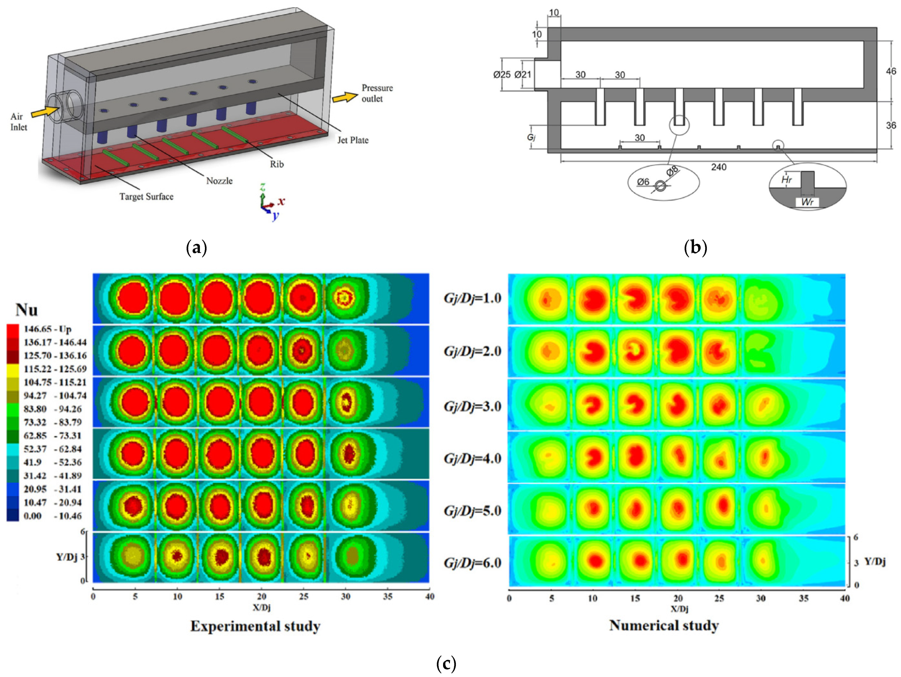
  59. Tepe, A.U.; Uysal, A.; Yetişken, Y.; Arslan, K. Jet impingement cooling on a rib-roughened surface using extended jet holes. Appl. Therm. Eng. 2020, 178, 115601. [Google Scholar] [CrossRef]
  60. Tong, F.; Gou, W.; Zhao, Z.; Gao, W.; Li, H.; Li, L. Numerical investigation of impingement heat transfer on smooth and roughened surfaces in a high-pressure turbine inner casing. Int. J. Therm. Sci. 2019, 149, 106186. [Google Scholar] [CrossRef]
  61. Singh, S.; Chaurasiya, S.K.; Negi, B.S.; Chander, S.; Nemś, M.; Negi, S. Utilizing circular jet impingement to enhance thermal performance of solar air heater. Renew. Energy 2020, 154, 1327–1345. [Google Scholar] [CrossRef]
  62. Maithani, R.; Kumar, A.; Raghav, G.; Nagpal, M.; Kumar, B. Thermal analysis of jet impingement on hemispherical protrusion on heated surface. Exp. Heat Transf. 2020, 1–16. [Google Scholar] [CrossRef]
  63. Hadipour, A.; Zargarabadi, M.R.; Mohammadpour, J. Effects of a triangular guide rib on flow and heat transfer in a turbulent jet impingement on an asymmetric concave surface. Phys. Fluids 2020, 32, 075112. [Google Scholar] [CrossRef]
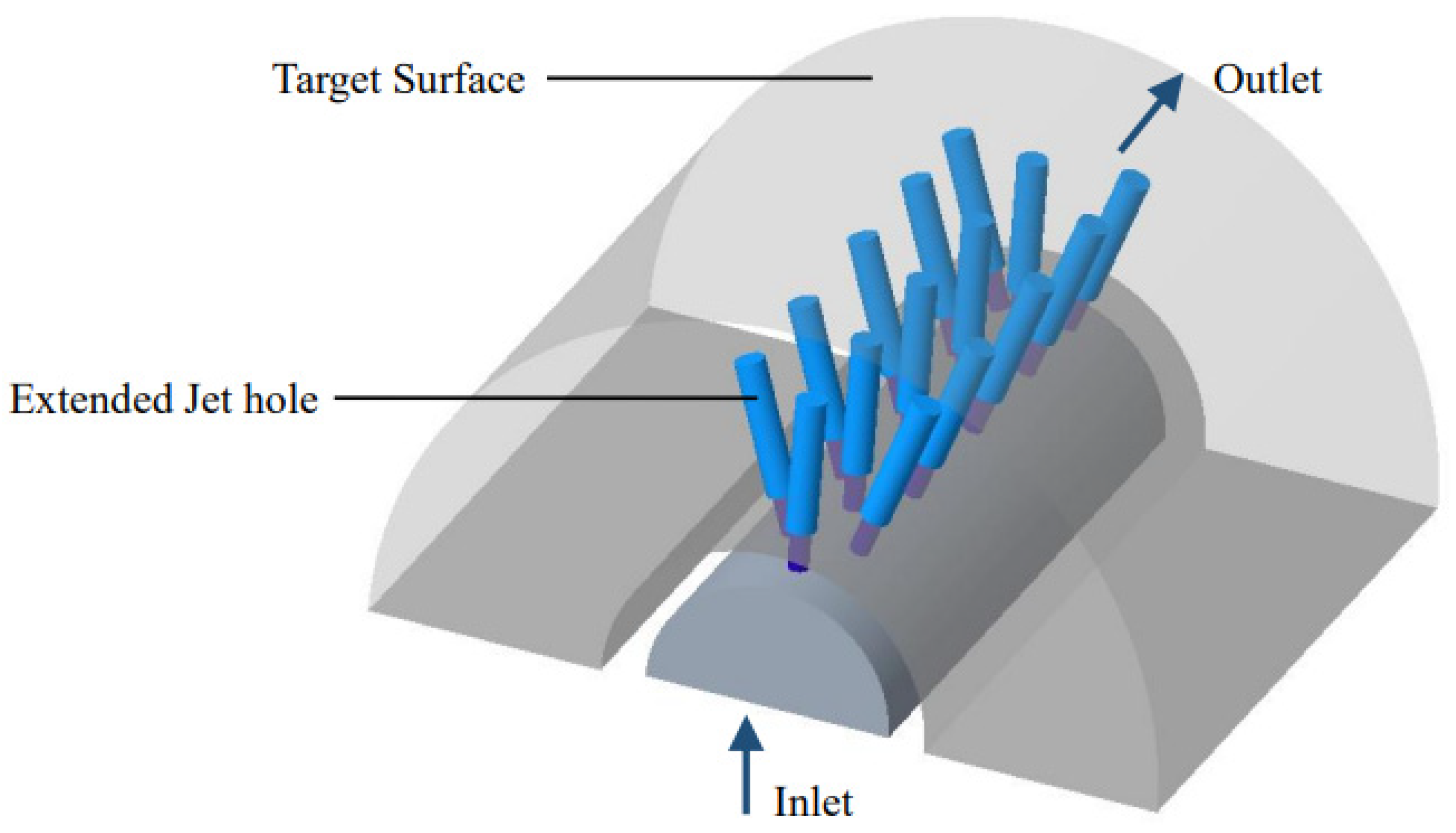
  64. Tepe, A.U. Numerical investigation of a novel jet hole design for staggered array jet impingement cooling on a semicircular concave surface. Int. J. Therm. Sci. 2020, 162, 106792. [Google Scholar] [CrossRef]
  65. Lytle, D.; Webb, B. Air jet impingement heat transfer at low nozzle-plate spacings. Int. J. Heat Mass Transf. 1994, 37, 1687–1697. [Google Scholar] [CrossRef]
  66. Lee, J.; Ren, Z.; Ligrani, P.; Fox, M.D.; Moon, H. International Journal of Thermal Sciences Cross flows from jet array impingement cooling: Hole spacing, target plate distance, Reynolds number effects. Int. J. Therm. Sci. 2015, 88, 7–18. [Google Scholar] [CrossRef]
  67. Madhavan, S.; Singh, P.; Ekkad, S.V. Jet Impingement Heat Transfer Enhancement by Packing High-Porosity Thin Metal Foams Between Jet Exit Plane and Target Surface. J. Therm. Sci. Eng. Appl. 2019, 11, 1–22. [Google Scholar] [CrossRef]
  68. Tepe, A.U.; Yetişken, Y.; Uysal, U.; Arslan, K. Experimental and numerical investigation of jet impingement cooling using extended jet holes. Int. J. Heat Mass Transf. 2020, 158, 119945. [Google Scholar] [CrossRef]
  69. Gao, F.; Chen, Y.; Cai, J.; Ma, C. Experimental study of free-surface jet impingement heat transfer with molten salt. Int. J. Heat Mass Transf. 2019, 149, 119160. [Google Scholar] [CrossRef]
  70. Ji, W.-T.; Lu, X.-D.; Chen, L.; Zhang, Y.-W.; Tao, W.-Q. Experimental investigation on the ice melting heat transfer with a steam jet impingement method. Int. Commun. Heat Mass Transf. 2020, 118, 104901. [Google Scholar] [CrossRef]
  71. Siddique, U.; Ansari, E.; Khan, S.A.; Patil, R. Numerical Investigation of Secondary Peaks in Nusselt Profile Under Water Jet Impingement. J. Thermophys. Heat Transf. 2020, 34, 421–428. [Google Scholar] [CrossRef]
  72. Yadav, S.; Saini, R. Numerical investigation on the performance of a solar air heater using jet impingement with absorber plate. Sol. Energy 2020, 208, 236–248. [Google Scholar] [CrossRef]
  73. Baghel, K.; Sridharan, A.; Murallidharan, J.S. Experimental and numerical study of inclined free surface liquid jet impingement. Int. J. Therm. Sci. 2020, 154, 106389. [Google Scholar] [CrossRef]
  74. Pratap, A.; Baghel, Y.; Patel, V.K. Effect of impingement height on the enhancement of heat transfer with circular confined jet impingement using nanofluids. Mater. Today Proc. 2020, 28, 1656–1661. [Google Scholar] [CrossRef]
  75. Forster, M.; Weigand, B. Experimental and numerical investigation of jet impingement cooling onto a concave leading edge of a generic gas turbine blade. Int. J. Therm. Sci. 2021, 164, 106862. [Google Scholar] [CrossRef]
  76. Alhajeri, H.M.; Almutairi, A.; Alenezi, A.; Gamil, A.A.; Al-Hajeri, M. Effect of mist/steam uniformity on heat transfer characteristics in unconfined jet impingement. Appl. Therm. Eng. 2020, 186, 116299. [Google Scholar] [CrossRef]
  77. Zhang, D.; Qu, H.; Lan, J.; Chen, J.; Xie, Y. Flow and heat transfer characteristics of single jet impinging on protrusioned surface. Int. J. Heat Mass Transf. 2013, 58, 18–28. [Google Scholar] [CrossRef]
  78. Selimefendigil, F.; Öztop, H.F. Jet impingement cooling and optimization study for a partly curved isothermal surface with CuO-water nano fluid. Int. Commun. Heat Mass Transf. 2017, 89, 211–218. [Google Scholar] [CrossRef]
  79. Wongcharee, K.; Chuwattanakul, V.; Eiamsa-Ard, S. Influence of CuO/water nanofluid concentration and swirling flow on jet impingement cooling. Int. Commun. Heat Mass Transf. 2017, 88, 277–283. [Google Scholar] [CrossRef]
  80. Feng, X.; Cousineau, E.; Bennion, K.; Moreno, G.; Kekelia, B.; Narumanchi, S. Experimental and numerical study of heat transfer characteristics of single-phase free-surface fan jet impingement with automatic transmission fluid. Int. J. Heat Mass Transf. 2020, 166, 120731. [Google Scholar] [CrossRef]
  81. Sundaram, R.D.; Madhavan, S.; Singh, P.; Ekkad, S.V. Enhanced fin-effectiveness of micro-scale concentric-shape roughened target surface subjected to array jet impingement. Int. J. Heat Mass Transf. 2021, 173, 121148. [Google Scholar] [CrossRef]
  82. Sagot, B.; Antonini, G.; Christgen, A.; Buron, F. Jet impingement heat transfer on a flat plate at a constant wall temperature. Int. J. Therm. Sci. 2008, 47, 1610–1619. [Google Scholar] [CrossRef]
  83. Li, W.; Li, X.; Yang, L.; Ren, J.; Jiang, H.; Ligrani, P. Effect of Reynolds number, hole patterns, and hole inclination on cooling performance of an impinging jet array-part I: Convective heat transfer results and optimization. J. Turbomach. 2017, 139, 1–11. [Google Scholar] [CrossRef]
  84. Ansu, U.; Godi, S.C.; Pattamatta, A.; Balaji, C. Experimental investigation of the inlet condition on jet impingement heat transfer using liquid crystal thermography. Exp. Therm. Fluid Sci. 2017, 80, 363–375. [Google Scholar] [CrossRef]
  85. Greco, C.S.; Paolillo, G.; Ianiro, A.; Cardone, G.; de Luca, L. Effects of the stroke length and nozzle-to-plate distance on synthetic jet impingement heat transfer. Int. J. Heat Mass Transf. 2018, 117, 1019–1031. [Google Scholar] [CrossRef]
  86. Glaspell, A.W.; Rouse, V.J.; Friedrich, B.K.; Choo, K. Heat transfer and hydrodynamics of air assisted free water jet impingement at low nozzle-to-surface distances. Int. J. Heat Mass Transf. 2018, 132, 138–142. [Google Scholar] [CrossRef]
  87. Markal, B.; Avci, M.; Aydin, O. Conical coaxial impinging air jets: Angle effect on the heat transfer performance. Heat Mass Transf. 2020, 56, 3135–3146. [Google Scholar] [CrossRef]
  88. Chen, L.; Brakmann, R.G.; Weigand, B.; Poser, R. An experimental heat transfer investigation of an impingement jet array with turbulators on both target plate and impingement plate. Appl. Therm. Eng. 2020, 166, 114661. [Google Scholar] [CrossRef]
  89. Maghrabie, H.M. Heat transfer intensification of jet impingement using exciting jets—A comprehensive review. Renew. Sustain. Energy Rev. 2021, 139, 110684. [Google Scholar] [CrossRef]
  90. Xu, L.; Xiong, Y.; Xi, L.; Gao, J.; Li, Y.; Zhao, Z. Numerical Simulation of Swirling Impinging Jet Issuing from a Threaded Hole under Inclined Condition. Entropy 2019, 22, 15. [Google Scholar] [CrossRef] [Green Version]
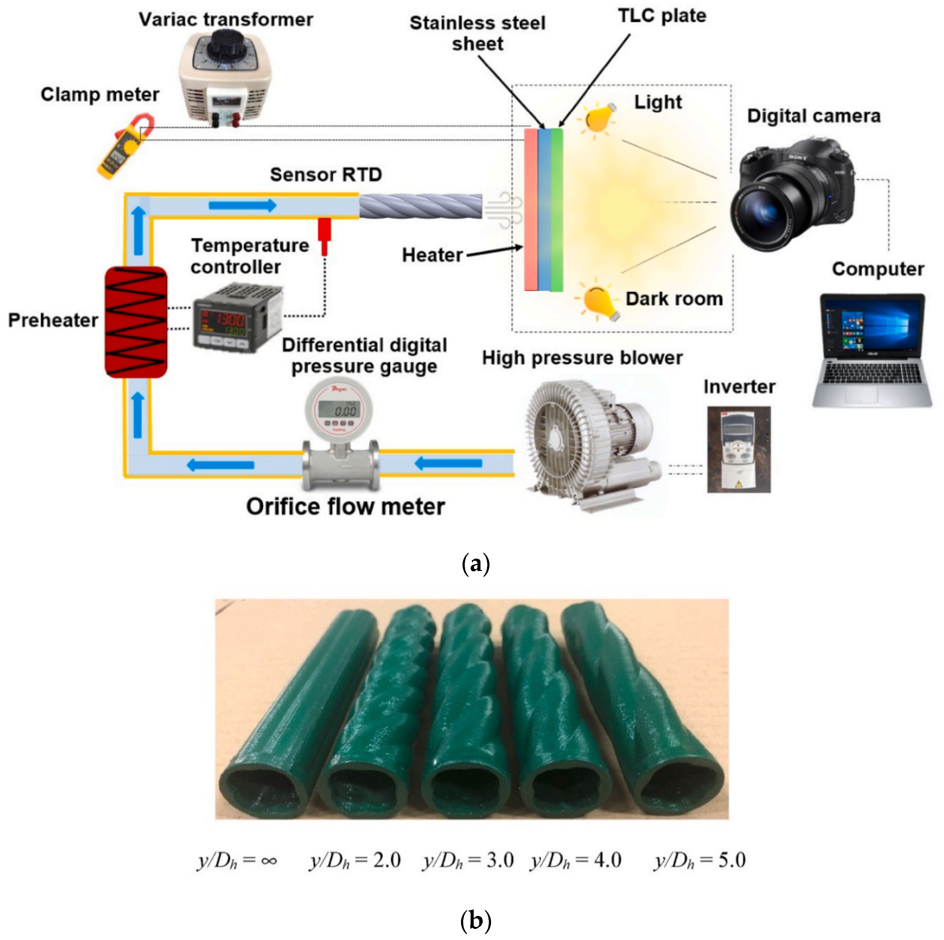
  91. Wongcharee, K.; Kunnarak, K.; Chuwattanakul, V.; Eiamsa-Ard, S. Heat transfer rate of swirling impinging jets issuing from a twisted tetra-lobed nozzle. Case Stud. Therm. Eng. 2020, 22, 100780. [Google Scholar] [CrossRef]
  92. Ikhlaq, M.; Al-Abdeli, Y.M.; Khiadani, M. Nozzle exit conditions and the heat transfer in non-swirling and weakly swirling turbulent impinging jets. Heat Mass Transf. 2019, 56, 269–290. [Google Scholar] [CrossRef]
  93. Debnath, S.; Khan, H.U.; Ahmed, Z.U. Turbulent swirling impinging jet arrays: A numerical study on fluid flow and heat transfer. Therm. Sci. Eng. Prog. 2020, 19, 100580. [Google Scholar] [CrossRef]
  94. Sapra, G.; Chander, S. Effect of operating and geometrical parameters of tangential entry type dual swirling flame burner on impingement heat transfer. Appl. Therm. Eng. 2020, 181, 115936. [Google Scholar] [CrossRef]
  95. Chang, S.W.; Shen, H.-D. Heat transfer characteristics of swirling impinging jet-arrays issued from nozzle plates with and without webbed grooves. Int. J. Therm. Sci. 2019, 148, 106155. [Google Scholar] [CrossRef]
  96. Chang, S.; Hsieh, M.-F.; Cai, W.-L.; Shen, H.-D. Detailed heat transfer measurements of impinging swirling and non-swirling jet arrays emitted from grooved orifice plate. Chem. Eng. Process. Process. Intensif. 2020, 149, 107820. [Google Scholar] [CrossRef]
  97. Fawzy, H.; Zheng, Q.; Ahmad, N.; Jiang, Y. Optimization of A Swirl with Impingement Compound Cooling Unit for A Gas Turbine Blade Leading Edge. Energies 2020, 13, 210. [Google Scholar] [CrossRef] [Green Version]
  98. Fawzy, H.; Zheng, Q.; Ahmad, N. Effect of Slot Area Ratio and Slot Angle on Swirl Cooling in a Gas Turbine Blade Leading Edge. J. Aerosp. Eng. 2020, 33, 04020046. [Google Scholar] [CrossRef]
  99. Park, T.; Kara, K.; Kim, D. Flow structure and heat transfer of a sweeping jet impinging on a flat wall. Int. J. Heat Mass Transf. 2018, 124, 920–928. [Google Scholar] [CrossRef]
  100. Zhou, W.; Yuan, L.; Liu, Y.; Peng, D.; Wen, X. Heat transfer of a sweeping jet impinging at narrow spacings. Exp. Therm. Fluid Sci. 2019, 103, 89–98. [Google Scholar] [CrossRef]
  101. Wen, X.; Liu, J.; Li, Z.; Peng, D.; Zhou, W.; Kim, K.C.; Liu, Y. Jet impingement using an adjustable spreading-angle sweeping jet. Aerosp. Sci. Technol. 2020, 105, 105956. [Google Scholar] [CrossRef]
  102. Kim, M.; Kim, D.; Yeom, E.; Kim, K.C. Experimental study on heat transfer and flow structures of feedback-free sweeping jet impinging on a flat surface. Int. J. Heat Mass Transf. 2020, 159, 120085. [Google Scholar] [CrossRef]
  103. Afroz, F.; Sharif, M.A. Numerical investigation of heat transfer from a plane surface due to turbulent annular swirling jet impingement. Int. J. Therm. Sci. 2020, 151, 106257. [Google Scholar] [CrossRef]
  104. Dutta, P.; Chattopadhyay, H. Computational analysis of heat transfer due to turbulent annular jet impingement. IOP Conf. Ser. Mater. Sci. Eng. 2021, 1080, 012031. [Google Scholar] [CrossRef]
  105. Fénot, M.; Dorignac, E.; Lantier, R. Heat transfer and flow structure of a hot annular impinging jet. Int. J. Therm. Sci. 2021, 170, 107091. [Google Scholar] [CrossRef]
  106. Huang, L.; Yeom, T.; Simon, T.; Cui, T. An experimental and numerical study on heat transfer enhancement of a heat sink fin by synthetic jet impingement. Heat Mass Transf. 2020, 57, 583–593. [Google Scholar] [CrossRef]
  107. Singh, P.K.; Sahu, S.K.; Upadhyay, P.K.; Jain, A.K. Experimental investigation on thermal characteristics of hot surface by synthetic jet impingement. Appl. Therm. Eng. 2019, 165, 114596. [Google Scholar] [CrossRef]
  108. Travnicek, Z.; Antosova, Z. Impingement heat transfer to the synthetic jet issuing from a nozzle with an oscillating cross section. Int. J. Therm. Sci. 2020, 153, 106349. [Google Scholar] [CrossRef]
  109. Singh, P.K.; Sahu, S.K.; Upadhyay, P.K. Experimental investigation of the thermal behavior a single-cavity and multiple-orifice synthetic jet impingement driven by electromagnetic actuator for electronics cooling. Exp. Heat Transf. 2020, 1–27. [Google Scholar] [CrossRef]
  110. Lyu, Y.-W.; Zhang, J.-Z.; Tang, C.; Tan, X.-M. Temperature-variation effect of piston-driven synthetic jet and its influence on definition of heat transfer coefficient. Int. J. Heat Mass Transf. 2020, 152, 119347. [Google Scholar] [CrossRef]
  111. Gil, P.; Wilk, J. Heat transfer coefficients during the impingement cooling with the use of synthetic jet. Int. J. Therm. Sci. 2019, 147, 106132. [Google Scholar] [CrossRef]
  112. Gil, P.; Wilk, J.; Smusz, R.; Gałek, R. Centerline heat transfer coefficient distributions of synthetic jets impingement cooling. Int. J. Heat Mass Transf. 2020, 160, 120147. [Google Scholar] [CrossRef]
  113. Lyu, Y.-W.; Zhang, J.-Z.; Tan, J.-W.; Shan, Y. Impingement heat transfer on flat and concave surfaces by piston-driven synthetic jet from planar lobed orifice. Int. J. Heat Mass Transf. 2020, 167, 120832. [Google Scholar] [CrossRef]
  114. Talapati, R.; Katti, V.; Hiremath, N. Local heat transfer characteristics of synthetic air jet impinging on a smooth convex surface. Int. J. Therm. Sci. 2021, 170, 107143. [Google Scholar] [CrossRef]
  115. Tang, C.; Zhang, J.-Z.; Lyu, Y.-W.; Tan, X.-M. Convective heat transfer on a flat target surface impinged by pulsating jet with an additional transmission chamber. Heat Mass Transf. 2019, 56, 183–205. [Google Scholar] [CrossRef]
  116. Abishek, S.; Narayanaswamy, R. Low Frequency Pulsating Jet Impingement Boiling and Single Phase Heat Transfer. Int. J. Heat Mass Transf. 2020, 159, 120052. [Google Scholar] [CrossRef]
  117. Ahmed, Z.U.; Al-Abdeli, Y.; Guzzomi, F.G. Flow field and thermal behaviour in swirling and non-swirling turbulent impinging jets. Int. J. Therm. Sci. 2017, 114, 241–256. [Google Scholar] [CrossRef]
  118. Wu, F.; Li, L.; Wang, J.; Fan, X.; Du, C. Numerical investigations on flow and heat transfer of swirl and impingement composite cooling structures of turbine blade leading edge. Int. J. Heat Mass Transf. 2019, 144, 118625. [Google Scholar] [CrossRef]
  119. Markal, B. The effect of Total flowrate on the cooling performance of swirling coaxial impinging jets. Heat Mass Transf. 2019, 55, 3275–3288. [Google Scholar] [CrossRef]
  120. Singh, P.; Chander, S. Effect of Interactions on Flow Field and Heat Transfer Characteristics for Three Corotating Dual Swirling Flames Impinging on a Flat Surface. Combust. Sci. Technol. 2019, 192, 701–727. [Google Scholar] [CrossRef]
  121. Hossain, M.A.; Prenter, R.; Lundgreen, R.K.; Ameri, A.; Gregory, J.W.; Bons, J.P. Experimental and Numerical Investigation of Sweeping Jet Film Cooling. J. Turbomach. 2017, 140, 031009. [Google Scholar] [CrossRef] [Green Version]
  122. Kim, S.H.; Kim, H.D.; Kim, K.C. Measurement of two-dimensional heat transfer and flow characteristics of an impinging sweeping jet. Int. J. Heat Mass Transf. 2019, 136, 415–426. [Google Scholar] [CrossRef]
  123. Kim, D.J.; Jeong, S.; Park, T.; Kim, D. Impinging sweeping jet and convective heat transfer on curved surfaces. Int. J. Heat Fluid Flow 2019, 79, 108458. [Google Scholar] [CrossRef]
  124. Agrawal, C.; Lyons, O.F.; Kumar, R.; Gupta, A.; Murray, D.B. Rewetting of a hot horizontal surface through mist jet impingement cooling. Int. J. Heat Mass Transf. 2013, 58, 188–196. [Google Scholar] [CrossRef]
  125. Khangembam, C.; Singh, D. Experimental Investigation of Air–Water Mist Jet Impingement Cooling Over a Heated Cylinder. J. Heat Transf. 2019, 141, 082201. [Google Scholar] [CrossRef]
  126. Khangembam, C.; Singh, D.; Handique, J.; Singh, K. Experimental and numerical study of air-water mist jet impingement cooling on a cylinder. Int. J. Heat Mass Transf. 2020, 150, 119368. [Google Scholar] [CrossRef]
  127. Guan, T.; Zhang, J.-Z.; Shan, Y.; Hang, J. Conjugate heat transfer on leading edge of a conical wall subjected to external cold flow and internal hot jet impingement from chevron nozzle—Part 1: Experimental analysis. Int. J. Heat Mass Transf. 2017, 106, 329–338. [Google Scholar] [CrossRef]
  128. Guan, T.; Zhang, J.-Z.; Shan, Y. Conjugate heat transfer on leading edge of a conical wall subjected to external cold flow and internal hot jet impingement from chevron nozzle—Part 2: Numerical analysis. Int. J. Heat Mass Transf. 2017, 106, 339–355. [Google Scholar] [CrossRef]
  129. Li, P.; Huang, X.; Guo, D. Numerical analysis of dominant parameters in synthetic impinging jet heat transfer process. Int. J. Heat Mass Transf. 2020, 150, 119280. [Google Scholar] [CrossRef]
  130. Hsu, C.M.; Jhan, W.C.; Chang, Y.Y. Flow and heat transfer characteristics of a pulsed jet impinging on a flat plate. Heat Mass Transf. 2019, 56, 143–160. [Google Scholar] [CrossRef]
  131. Rakhsha, S.; Zargarabadi, M.R.; Saedodin, S. Experimental and numerical study of flow and heat transfer from a pulsed jet impinging on a pinned surface. Exp. Heat Transf. 2020, 34, 376–391. [Google Scholar] [CrossRef]
  132. Nguyen, C.T.; Galanis, N.; Polidori, G.; Fohanno, S.; Popa, C.V.; Le Bechec, A. An experimental study of a confined and submerged impinging jet heat transfer using Al2O3-water nanofluid. Int. J. Therm. Sci. 2009, 48, 401–411. [Google Scholar] [CrossRef]
  133. Naphon, P.; Wongwises, S. Experimental Study of Jet Nanofluids Impingement System for Cooling Computer Processing Unit. J. Electron. Cool. Therm. Control 2011, 1, 38–44. [Google Scholar] [CrossRef] [Green Version]
  134. Zeitoun, O.; Ali, M. Nanofluid impingement jet heat transfer. Nanoscale Res. Lett. 2012, 7, 139. [Google Scholar] [CrossRef] [Green Version]
  135. Naphon, P.; Nakharintr, L. Nanofluid jet impingement heat transfer characteristics in the rectangular mini-fin heat sink. J. Eng. Phys. Thermophys. 2012, 85, 1432–1440. [Google Scholar] [CrossRef]
  136. Jaberi, B.; Youse, T.; Farahbakhsh, B.; Saghir, M.Z. Experimental investigation on heat transfer enhancement due to Al2O3-water nano fluid using impingement of round jet on circular disk. Int. J. Therm. Sci. 2013, 74, 199–207. [Google Scholar] [CrossRef]
  137. Zhou, M.; Xia, G.; Chai, L. Heat transfer performance of submerged impinging jet using silver nanofluids. Heat Mass Transf. 2014, 51, 221–229. [Google Scholar] [CrossRef]
  138. Lv, J.; Hu, C.; Bai, M.; Zeng, K.; Chang, S.; Gao, D. Experimental investigation of free single jet impingement using SiO2-water nanofluid. Exp. Therm. Fluid Sci. 2017, 84, 39–46. [Google Scholar] [CrossRef]
  139. Selimefendigil, F.; Öztop, H.F. Effects of Nanoparticle Shape on Slot-Jet Impingement Cooling of a Corrugated Surface With Nanofluids. J. Therm. Sci. Eng. Appl. 2017, 9, 021016. [Google Scholar] [CrossRef]
  140. Mahdavi, M.; Sharifpur, M.; Meyer, J.P.; Chen, L. Thermal analysis of a nanofluid free jet impingement on a rotating disk using volume of fluid in combination with discrete modelling. Int. J. Therm. Sci. 2020, 158, 106532. [Google Scholar] [CrossRef]
  141. Abhijith, M.; Venkatasubbaiah, K. Numerical investigation of jet impingement flows with different nanofluids in a mini channel using Eulerian-Eulerian two-phase method. Therm. Sci. Eng. Prog. 2020, 19, 100585. [Google Scholar]
  142. Ekiciler, R.; Çetinkaya, M.S.A.; Arslan, K. Effect of shape of nanoparticle on heat transfer and entropy generation of nanofluid-jet impingement cooling. Int. J. Green Energy 2020, 17, 555–567. [Google Scholar] [CrossRef]
  143. Abdelrehim, O.; Khater, A.; Mohamad, A.; Radwan, A. Two-phase simulation of nanofluid in a confined single impinging jet. Case Stud. Therm. Eng. 2019, 14, 100423. [Google Scholar] [CrossRef]
  144. Barewar, S.D.; Chougule, S.S. Heat transfer characteristics and boiling heat transfer performance of novel Ag/ZnO hybrid nanofluid using free surface jet impingement. Exp. Heat Transf. 2020, 34, 531–546. [Google Scholar] [CrossRef]
  145. Chen, W.; Cheng, J. A numerical analysis on the heat transfer of jet impingement with nanofluid on a concave surface covered with metal porous block. Heat Mass Transf. 2020, 56, 3071–3083. [Google Scholar] [CrossRef]
  146. Selimefendigil, F.; Öztop, H.F. Combined effects of double porous layers and nanofluids on the performance of confined single and multi-jet impingement heat transfer. Chem. Eng. Commun. 2021, 1–13. [Google Scholar] [CrossRef]
  147. Selimefendigil, F.; Öztop, H.F. Al2O3-Water Nanofluid Jet Impingement Cooling With Magnetic Field. Heat Transf. Eng. 2018, 41, 50–64. [Google Scholar] [CrossRef]
  148. Sun, B.; Zhang, Y.; Yang, D.; Li, H. Experimental study on heat transfer characteristics of hybrid nano fluid impinging jets. Appl. Therm. Eng. 2019, 151, 556–566. [Google Scholar] [CrossRef]
  149. Sorour, M.M.; El-maghlany, W.M.; Alnakeeb, M.A.; Abbass, A.M. Experimental study of free single jet impingement utilizing high concentration SiO2 nanoparticles water base nano fluid. Appl. Therm. Eng. 2019, 160, 114019. [Google Scholar] [CrossRef]
  150. Kareem, Z.S.; Balla, H.H.; Abdulwahid, A.F. Case Studies in Thermal Engineering Heat transfer enhancement in single circular impingement jet by CuO-water nanofluid. Case Stud. Therm. Eng. 2019, 15, 100508. [Google Scholar] [CrossRef]
  151. Amjadian, M.; Safarzadeh, H.; Bahiraei, M.; Nazari, S.; Jaberi, B. Heat transfer characteristics of impinging jet on a hot surface with constant heat flux using Cu2O-water nano fluid: An experimental study. Int. Commun. Heat Mass Transf. 2020, 112, 104509. [Google Scholar] [CrossRef]
  152. Allauddin, U.; Jamil, T.; Shakaib, M.; Khan, H.M.U.; Mohiuddin, R.; Saeed, M.S.; Ahsan, H.; Uddin, N. Heat Transfer Enhancement Caused by Impinging Jets of Al2O3-Water Nanofluid on Amicro-Pin Fin Roughened Surface under Crossflow Conditions-A Numerical Study. J. Enhanc. Heat Transf. 2020, 27, 367–387. [Google Scholar] [CrossRef]
  153. Balla, H.H.; Kareem, Z.S.; Abdulwahid, A. Experimental study of Zn-water nanofluid heat transfer enhancement through an oval twin impingement jet. IOP Conf. Ser. Mater. Sci. Eng. 2020, 870, 012173. [Google Scholar] [CrossRef]
  154. Al-Zuhairy, R.C.; Kareem, Z.S.; Abduhadi, A.A. Al2O3-water nanofluid heat transfer enhancement of a twin impingement jet. Case Stud. Therm. Eng. 2020, 19, 100626. [Google Scholar] [CrossRef]
  155. Sodagar-Abardeh, J.; Edalati-Nejad, A.; Torkamani, K.; Nasery, P. CFD modeling and analysis of effect of nanoparticle shape on heat transfer of confined slot-jet impingement with nanofluid. Microfluid. Nanofluidics 2021, 25, 49. [Google Scholar] [CrossRef]
  156. Balla, H.H.; Liaq, A.; Kareem, Z.S.; Abdulwahid, A.F. Case Studies in Thermal Engineering Heat transfer potentials of ZnO/water nanofluid in free impingement jet. Case Stud. Therm. Eng. 2021, 27, 101143. [Google Scholar] [CrossRef]
  157. Parida, P.R.; Ekkad, S.V.; Ngo, K. Novel PCM and Jet Impingement Based Cooling Scheme for High Density Transient Heat Loads. In Proceedings of the 2010 14th International Heat Transfer Conference, Washington, DC, USA, 8–13 August 2010; pp. 443–450. [Google Scholar] [CrossRef]
  158. Wu, W.; Bostanci, H.; Chow, L.; Ding, S.; Hong, Y.; Su, M.; Kizito, J.; Gschwender, L.; Snyder, C. Jet impingement and spray cooling using slurry of nanoencapsulated phase change materials. Int. J. Heat Mass Transf. 2011, 54, 2715–2723. [Google Scholar] [CrossRef]
  159. Wu, W.; Bostanci, H.; Chow, L.C.; Hong, Y.; Ding, S.J.; Su, M.; Kizito, J.P. Jet Impingement Heat Transfer Using Air-Laden Nanoparticles with Encapsulated Phase Change Materials. J. Heat Transf. 2013, 135, 052202. [Google Scholar] [CrossRef]
  160. Seyf, H.R.; Zhou, Z.; Ma, H.; Zhang, Y. Three dimensional numerical study of heat-transfer enhancement by nano-encapsulated phase change material slurry in microtube heat sinks with tangential impingement. Int. J. Heat Mass Transf. 2013, 56, 561–573. [Google Scholar] [CrossRef]
  161. Hong, F.J.; Zhang, C.Y.; Chen, D.H.; Chen, G. Confined jet array impingement cooling using NEPCM nanofluids. In Proceedings of the ASME 2016 5th International Conference on Micro/Nanoscale Heat and Mass Transfer (MNHMT), Singapore, 4–6 January 2016; Volume 1, pp. 1–6. [Google Scholar]
  162. Rehman, M.M.U.; Qu, Z.G.; Fu, R.P. Three-dimensional numerical study of laminar confined slot jet impingement cooling using slurry of nano-encapsulated phase change material. J. Therm. Sci. 2016, 25, 431–439. [Google Scholar] [CrossRef]
  163. Rehman, M.M.U.; Qu, Z.; Fu, R.; Xu, H. Numerical study on free-surface jet impingement cooling with nanoencapsulated phase-change material slurry and nanofluid. Int. J. Heat Mass Transf. 2017, 109, 312–325. [Google Scholar] [CrossRef]
  164. Zhang, J.; Yang, C.; Jin, Z.; Ma, S.; Pang, X. Experimental study of jet impingement heat transfer with microencapsulated phase change material slurry. Appl. Therm. Eng. 2021, 188, 116588. [Google Scholar] [CrossRef]
Figure 1. (a) Flow regions of the impinging jet and (b) main flow zones of the free jet. Reprinted with permission [21], Copyright 1993, Elsevier.
Energies 14 06458 g001
Figure 2. Physical model of jet impingement. Reprinted with permission [45], Copyright 2018, Elsevier.
Energies 14 06458 g002
Figure 3. (a,b) Contour plots of axial velocity on the XOY plane and the YOZ plane and (c) cloud plots of the Nu/Nust ratio. Reprinted with permission [47], Copyright 2021, Elsevier.
Energies 14 06458 g003aEnergies 14 06458 g003b
Figure 4. Test section (a) 3D view and (b) cross-sectional view and (c) effect of Gj/Dj on the local Nu at rib height Hr/Dj = 0.42. Reprinted with permission [59], Copyright 2020, Elsevier.
Energies 14 06458 g004
Figure 5. Various surface configurations: (a) squared pin fin, (b) smooth, (c) cambered rib, and (d) round pin fin. Adopted from [60].
Energies 14 06458 g005
Figure 6. Schematic view of the physical model of the test section. Adopted from [64].
Energies 14 06458 g006
Figure 7. Heat transfer performance at different values of jet nozzle–target plate spacing (H/D) and Re. Reprinted with permission [76], Copyright 2021, Elsevier.
Energies 14 06458 g007
Figure 8. (a) Schematic of the experimental setup and (b) twisted tetra-lobed nozzle. Reprinted with permission [91], Copyright 2020, Elsevier.
Energies 14 06458 g008
Figure 9. Design of a master–slave oscillator (adopted from [101], 2020 Elsevier).
Energies 14 06458 g009
Figure 10. Average Nu profile against impingement of a feedback-free sweeping jet (FFSJ), normal-feedback sweeping jet (FSJ), and steady square jet (SJ) for various jet-to-wall spacings and Reynolds numbers. Reprinted with permission [102], Copyright 2020, Elsevier.
Energies 14 06458 g010
Figure 11. Schematic diagram of the experimental setup for piston-driven synthetic jet impingement. Reprinted with permission [110], Copyright 2020, Elsevier.
Energies 14 06458 g011
Figure 12. Schematic diagram of the experimental setup for synthetic jet impingement using a special actuator comprising a loudspeaker and a Plexiglass cavity. Adopted from [111].
Energies 14 06458 g012
Figure 13. Schematic diagram of the lobed orifices used. Reprinted with permission [113], Copyright 2020, Elsevier.
Energies 14 06458 g013
Figure 14. Nu values for different percentages of SiO2 nanoparticles in water at (a) H/D = 2, (b) H/D = 3, (c) H/D = 4, and (d) H/D = 5. Reprinted with permission [138], Copyright 2017, Elsevier.
Energies 14 06458 g014
Figure 15. Variations of the Nusselt number (a) along the impinging jet as a function of the volume fraction (ϕ) and (b) variations of the average Nusselt number as a function of the volume fraction (ϕ). Reprinted with permission [143], Copyright 2019, Elsevier.
Energies 14 06458 g015
Figure 16. Images of encapsulated nanoparticles using (a) scanning electron microscopy and (b) transmission electron microscopy; (c) particle size distribution of encapsulated nanoparticles; (d) schematic diagram of the test chamber and heating element. Reprinted with permission [158], Copyright 2011, Elsevier.
Energies 14 06458 g016
Figure 17. Schematic diagram of the test chamber and heating element. Reprinted with permission [164], Copyright 2021, Elsevier.
Energies 14 06458 g017aEnergies 14 06458 g017b
Table 1. Important geometrical parameters used in jet impingement.
ParameterPurpose
Reynolds numberIt is a ratio of inertial forces to viscous forces. It helps to assess turbulence effects by relating the jet velocity and nozzle diameter to the kinematic viscosity of the fluid.
Nusselt numberIt is a ratio of convection–conduction heat transfer. It helps to quantify the thermal enhancement of a jet impinging method.
Prandtl numberIt is a ratio of momentum diffusivity to thermal diffusivity. It accounts for the effect of hydrodynamic and thermal boundary layers for different types of impinging fluids.
Jet–target surface distance ratioIt is the spacing between jet plate and target surface. The stagnation zone and fluid–surface interactions of the impinging jets depend on the jet nozzle–target surface distance.
Jet–jet spacingThe spacing between adjacent jets. This is an important parameter to account for jet-to-jet interactions in thermal-hydraulic performance improvement of the target surface.
Table 2. Jet impingement at various shapes of target surfaces.
Ref.Target Surface ShapeVariable ParametersKey RemarksFigure of Target Surface
McInturff et al. [48]TriangularRe = 900, 1500, 5000, and 11,000.
Three jet array impingement hole shapes, i.e., circular, racetrack, and triangular, are used.
Addition of triangular roughness increases the heat transfer rate. Energies 14 06458 i001
Reprinted with permission [48], Copyright 2018, Elsevier.
Singh and Ekkad [49]V-shaped ribs and cylindrical dimplesRe = 19,500–69,000.
Ratio of rib height to diameter = 0.125.
Ratio of rib pitch to rib height = 16.
Ratio of dimple depth to print diameter = 0.3
The combined case of ribs and dimples gave better heat transfer and thermal-hydraulic performance as compared to ribs alone and dimples alone. Energies 14 06458 i002
Reprinted with permission [49], Copyright 2017, Elsevier.
Singh and Ekkad [50]DimpleRe = 2500.
Rotational speed = 400 rpm.
For non-rotating conditions, heat transfer was enhanced for the dimpled surface. Energies 14 06458 i003
Adopted from [50].
Vinze et al. [51]DimplePitch, p = 3 d, 4 d, and 5 d.
Dimple depth = 0.25 d and 0.5 d.
Orifice plate–test plate spacing = 1 d–6 d.
Pitch of 4d or higher improves heat transfer as compared to the flat surface. Energies 14 06458 i004
Adopted from [51].
Singh and Prasad [52]ConcaveChamfered and non-chamfered jet impingement configuration with constant pump power.
H/d = 3, 5, 7, and 9.
Re = 15,441–37,457.
8% to 24% increase in the thermal performance factor and mild impact of jet–plate spacing. Energies 14 06458 i005
Reprinted with permission [52], Copyright 2018, Elsevier.
Jordan et al. [53]ConcaveHole shapes: (i) cylindrical with Reynolds number = 13,600, 27,200, and 40,700 and (ii) racetrack shaped with Reynolds number = 11,500, 23,000, and 34,600.A direct relation of Nu with the Reynolds number for both hole shapes was reported.
The racetrack shape showed better heat transfer performance.
Energies 14 06458 i006
Adopted from [53].
Qiu et al. [54]ConcaveThe jet arrangement was varied.
Re = 10,000–40,000.
Jet–target spacing = 1.
Relative surface curvature = 10.
The performance of local heat transfer and fluid flow was analyzed.
Better uniformity of heat transfer was reported.
Energies 14 06458 i007
Adopted from [54].
Takeishi et al. [55]CircularRe = 10,000.
H/D = 3.0.
Circular ring height = 0.58, 0.98, and 1.42.
21% increase in the averaged area Nu for the circular ribs roughened surface. Energies 14 06458 i008
Reprinted with permission [55], Copyright 2020 MDPI.
Pachpute and Premacha-ndran [56]Circular CylinderRe = 4500–20,000.
Spacing between nozzle and target surface, H, and slot jet width, S, ratio, H/S = 2–10.
D/S = 1, 2, and 4.
The cooling rate was reduced by 25% by the confinement wall. Impact of the confinement wall is significant only for H/S equal to or less than 4. Energies 14 06458 i009
Reprinted with permission from [56], Copyright 2018, Elsevier.
Pachpute and Premachandran [57]Circular cylinderRe = 5000–20,000.
H/D = 2–12.
The average heat transfer was enhanced by 14% for H/D = 2 and Re = 20,000 for the staggered jet vs. inline jet arrangement. Energies 14 06458 i010
Adopted from [57].
Table 3. Impinging jets at various shapes of target surfaces and different jet/nozzle–target surface shapes.
Ref.MethodologyKey Findings
Zhang et al. [77]• Numerical study to investigate the flow and heat transfer characteristics of jet impingement on a target surface containing a protrusion.• Flow structures of the jet were found to be insensitive to the protrusion’s relative depth and the Reynolds number of the jet.
• The jet turned its flow direction after it impinged perpendicularly on the protrusion, while flow separation and secondary impinging jet formation occurred when flow passed through the region of the protrusion edge.
• An increase in the local Nu was observed in the case of the protrusion as compared to the smooth target surface.
• As the protrusion’s relative depth increased, it caused an increase in the local Nu and the overall heat transfer was observed to increase for most of the cases due to an increase in the heat transfer area and enhancement of heat transfer in the stagnation region.
Selimefendigil and Öztop [78]• Numerical study by impinging a jet over a partly curved surface with a CuO–water nanofluid.
• Simulations were performed for Re = 100–500 and various solid particle volume fractions.
• A more pronounced effect over heat transfer and distribution of fluid flow was observed for the curved surface as compared to the flat one.
• The average Nu increased linearly with the nanoparticle volume fraction, and a 20% enhancement in the average Nu was observed at the highest volume fraction. the
Wongcharee et al. [79]• Experimental study of the impact of three different jet–plate spacing–nozzle diameter ratios (H/d), 2, 3, and 4, over jet impingement cooling.• A decrease in Nu was experienced with the increase in the jet–plate spacing–nozzle diameter ratios (H/d).
• The poor heat transfer at a high jet–plate spacing–nozzle diameter ratios (H/d) was observed to be caused by the impinging jet of lower intensity having a lower momentum on the target plate.
Feng et al. [80]• Experimental and numerical study for five different nozzle–target plate distance values of H/D = 2, 4, 6, 8, and 10.• It was observed from the results that at a low value of H/Dm the heat transfer rate is enhanced as more fluid is provided for cooling.
Sundaram et al. [81]• Experimental and numerical investigation of heat transfer performance and pin-fin effectiveness of array jet impingement over a target surface having a roughness element of short height.
• Array of 5 × 5 jets had a jet–jet spacing (X/D = Y/D) of 3 and a jet–target spacing (Z/D) of 1.
• Pin-fin effectiveness significantly increased, and it was observed that the height of the roughness element (H) is the dominant factor affecting heat transfer.
• Effectiveness ranging between 1.8 and 2.4 was reported for the plate configurations used in this study, and the highest effectiveness was achieved by the configuration having the highest void fraction and wetted surface area.
Sagot et al. [82]• Numerical and experimental investigation of air jet impingement on a flat surface for various jet–target surface spacings (H/D = 2–6).
• A Nu correlation was proposed for constant wall temperature conditions.
• Lower values of Nu were obtained for the constant wall temperature in comparison with uniform heat flux.
Li et al. [83]• Heat transfer performance of an impinging jet array arrangement was studied experimentally for jet–target surface spacing Z/D = 0.75–3, and yjr hole inclination angle was varied from 0° to 40°.• An increase in Nu was observed with an increase in spacing between the jet and the target surface, and the peak value was reported at Z/D = 2.
• The hole inclination angle was insensitive to the area-averaged Nu; however, a small impact over the local heat transfer distribution was reported.
Ansu et al. [84]• An experimental investigation to study heat transfer performance over an unheated flat plate by impingement of a single jet and a row of jets for the jet–target surface spacing (L/D) of 2, 4, and 6.
• The study was performed for Reynolds number values of 5000, 10,000, and 15,000.
• A decrease in the stagnation Nu was observed for an increasing L/D value up to 4, and a decreasing trend was reported afterward until L/D = 6 for all Re values in the single-nozzle case.
• For the single-orifice case, a higher stagnation Nu value was observed for lower values of L/D.
• For the nozzle case, the separation distance L/D = 4 gave optimum extraction of heat from the target surface for both a single and a row of jets.
Greco et al. [85]• An experimental study was conducted to analyze the impact of the nozzle–target plate spacing H/D between 2 and 10 and for a fixed Reynolds number of 5250.• Heat transfer fluctuations showed a decreasing trend with an increase in the nozzle–target plate distance H/D.
• The maximum value of time-averaged stagnation Nu was observed at values between 4 and 6 for the jet–target plate spacing H/D.
Glaspell et al. [86]• An experimental investigation was performed to study the impact of the nozzle–target surface distance for a range of H/d = 0.02–0.51.• It was observed from the results that a decrease in the nozzle–target surface spacing causes an increase in the normalized stagnation Nu and hydraulic jump diameter.
Markal et al. [87]• A coaxial air impinging jet having an outer conical outlet and an inner circular outlet was studied experimentally to investigate heat transfer performance at nozzle exit–target surface distance H/D = 0.5–6 and cone angles of 0°, 10°, 20°, and 30°.• It was observed from the results that lower values of the distance between nozzle exit and target surface results in higher values of the local Nu, and the highest thermal performance was achieved for H/D = 2 or lower nozzle–target distances with cone angle 20°.
Chen et al. [88]• Experimental study to investigate heat transfer performance for a combined effect of detached ribs and V ribs on a target plate and an impingement plate, respectively.
• The investigation was performed for the separation distance H/D ranging from 3 to 5 and Re = 15,000 to 35,000.
• A higher area-averaged ratio of Nu for the Vi-detached rib case and the smooth case was obtained for H/D = 5 and Reynolds number = 35,000.
• For all cases of the Vi-detached rib, the Nu value was higher as compared to the Nu obtained for the smooth case, and the aerodynamic effects were observed to be the cause of the increase in heat transfer.
Table 4. Jet impingement with different types of excited jets.
Ref.Type of StudyType of Jet
Excitation
Key Findings
Ahmed et al. [117]Experimental/NumericalPassive/Swirling• The convective heat transfer for swirling jet impingement was found to be highest in the near field (low jet impingement distance), whereas for the far field (high jet impingent distance), the highest convective heat transfer was observed for the non-swirling jet.
• In only the strong swirling jet case, stable recirculation zones (which affect the heat transfer coefficient) appeared on the impinged surface for near-field impingement.
Wu et al. [118]NumericalPassive/Swirling• High local and uniform heat transfer regions were achieved through the combined effect of impingement and swirl cooling (swirl and impingement composite cooling).
• The composite swirl impingement case achieved a 19.12% higher global average Nu as compared to the impingement-only case and a 4.29% lower pressure loss as compared to the swirl-only case.
Markal et al. [119]ExperimentalPassive/Swirling• An enhancement in heat transfer was observed for coaxial swirling air impinging jets with an increase in the flow rate and a decrease in jet–target spacing.
• The magnitude of the local Nu increased by 17% when the flow rate was increased from 40 LPM to 50 LPM.
• A 10.6% and 29.7% increase in the average Nu was achieved through reducing the impingement distance and increasing the flow rate, respectively.
Singh and Chander [120]Experimental/NumericalPassive/Swirling• Co swirling adjacent jets caused strong interaction, which resulted in high turbulence and mixing, and thus high heat transfer rates were obtained.
• The effect of jet–jet spacing was observed to be more significant as compared to the jet–target surface distance.
Hossain et al. [121]Experimental/NumericalPassive/Sweeping• The fluidic oscillator caused significantly improved cooling effectiveness due to its sweeping action in the sweeping jet cooling hole.
• An improvement in overall cooling performance of the sweeping jet was observed at low blowing ratios.
Kim et al. [122]ExperimentalPassive/Sweeping• A significantly higher heat transfer performance due to enhanced thermal transport near the impingement surface was achieved by the motion of the sweeping jet as compared to a steady square jet.
•A drastic decrease in the heat transfer performance of sweeping jets was observed at higher jet–wall distances because of a reduction in impinging velocities.
Kim et al. [123]ExperimentalPassive/Sweeping• It was observed during the results that the sweeping jet enhances the heat transfer rate for a concave target surface as compared to a flat surface.
• The curvature magnitude resulted in peaks of Nu at moderate curvature, but no monotonic increase in Nu was observed otherwise.
Agrawal et al. [124]ExperimentalPassive/Annular• The results showed that using an axis-symmetric nozzle, the rewetting temperature increased by an increase in the initial temperature of the surface and an increase in wetting delay, but a reduction in rewetting velocity was also reported.
Khangem-bam and Singh [125]ExperimentalPassive/Annular• For a mist loading fraction range of 0.25–1.0%, an enhancement in the heat transfer coefficient at the stagnation point in the range of 185% to 312% was observed for the air–water mist impinging jet over the cylinder.
Khangem-bam et al. [126]Experimental/NumericalPassive/Annular• A significant enhancement in heat transfer was reported with the increased mist loading fraction.
• A high heat transfer enhancement of 408% and 775% at the stagnation point on the cylindrical surface was reported during the experimental and numerical study.
Guan et al. [127]ExperimentalActive/Synthetic• The results reported an improvement in the effectiveness of heating for a chevron jet on a conical wall’s leading edge for small Reynolds number values.
• A 20% enhancement in area average heating effectiveness was observed for the chevron nozzle jet in comparison to the conventional nozzle jet.
Guan et al. [128]NumericalActive/Synthetic• Heat transfer performance improved by a chevron nozzle in the vicinity of the leading edge of the conical wall by causing high jet fluctuations through an increase in the jet core velocity.
• For a constant chevron length ratio, the average heating effectiveness increased with an increase in the chevron penetration depth ratio.
Li et al. [129]NumericalActive/Synthetic• For all the Reynolds number values used in the study, the corresponding interval of the Strouhal number was reported to be 0.24–0.48 for the maximum average Nu.
• The trend of the amplitude and variation of the average Nu was reported to be significantly influenced by the Reynolds number or forcing frequency of the synthetic jet.
Hsu et al. [130]ExperimentalActive/Pulsating• Convective heat transfer was reported to be enhanced by increasing the axial convective velocity of the ring generated by the vortex and fluctuation intensity.
Rakhsha et al. [131]Experimental/NumericalActive/Pulsating• In comparison to steady jets, heat transfer enhancements of 21%, 30%, and 36% were reported for pulsating jet frequencies of 50, 80, and 100 Hz, respectively, at jet–target surface distance (H/d) = 5 and Re = 10,000.
• An increase in Nu was observed with an increase in the pulsating frequency and Reynolds number, while a reduction in Nu was reported with increasing spacing between jet and target surface.
Table 5. Jet impingement with nanofluids.
Ref.StudyNanofluidFlow Rate/Reynolds NumberHeat
Transfer
Performance
Selimefendigil and Öztop [147]NumericalAl2O3–water100–400Average heat transfer enhanced by 46%
Sun et al. [148]ExperimentalSilver–multiwall carbon nanotube (Ag-MWCNT)/water hybrid nanofluids0.1–0.6 m3·h−1Heat transfer coefficient enhanced by 29.45%
Sorour et al. [149]ExperimentalSiO2–water40,000Nu increased up to 80%
Kareem et al. [150]Experimental/NumericalCuO–water1000–80002.9% maximum enhancement in Nu
Amjadian et al. [151]ExperimentalCu2O–water7330–11,082Convective heat transfer enhanced by 45.7%
Allauddin et al. [152]NumericalAl2O3–water4000–20,000Heat transfer coefficient improved by 72%
Balla et al. [153]ExperimentalZn–water200–1000Nu enhanced by 2.1%
Al-Zuhairy et al. [154]ExperimentalAl2O3–water400–2000200% increase in Nu
Sodagar-Abardeh et al. [155]NumericalBoehmite alumina–water and ethylene glycol mixture (50:50)100–40083.3% increase in Nu
Balla et al. [156]ExperimentalZnO–water5000–17,500113.9% enhancement in Nu
Publisher’s Note: MDPI stays neutral with regard to jurisdictional claims in published maps and institutional affiliations.

