Thermoelectric Generation with Impinging Nano-Jets


Abstract
:
1. Introduction
2. Numerical Model
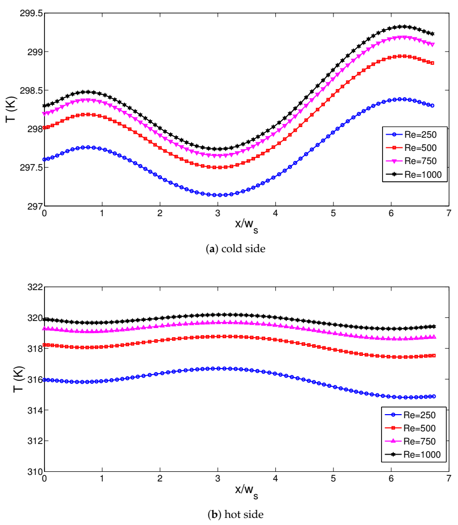
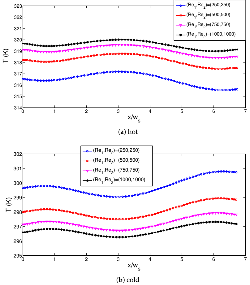
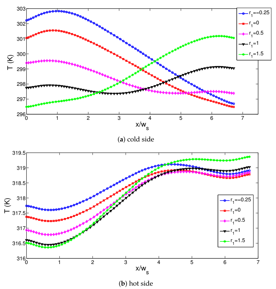
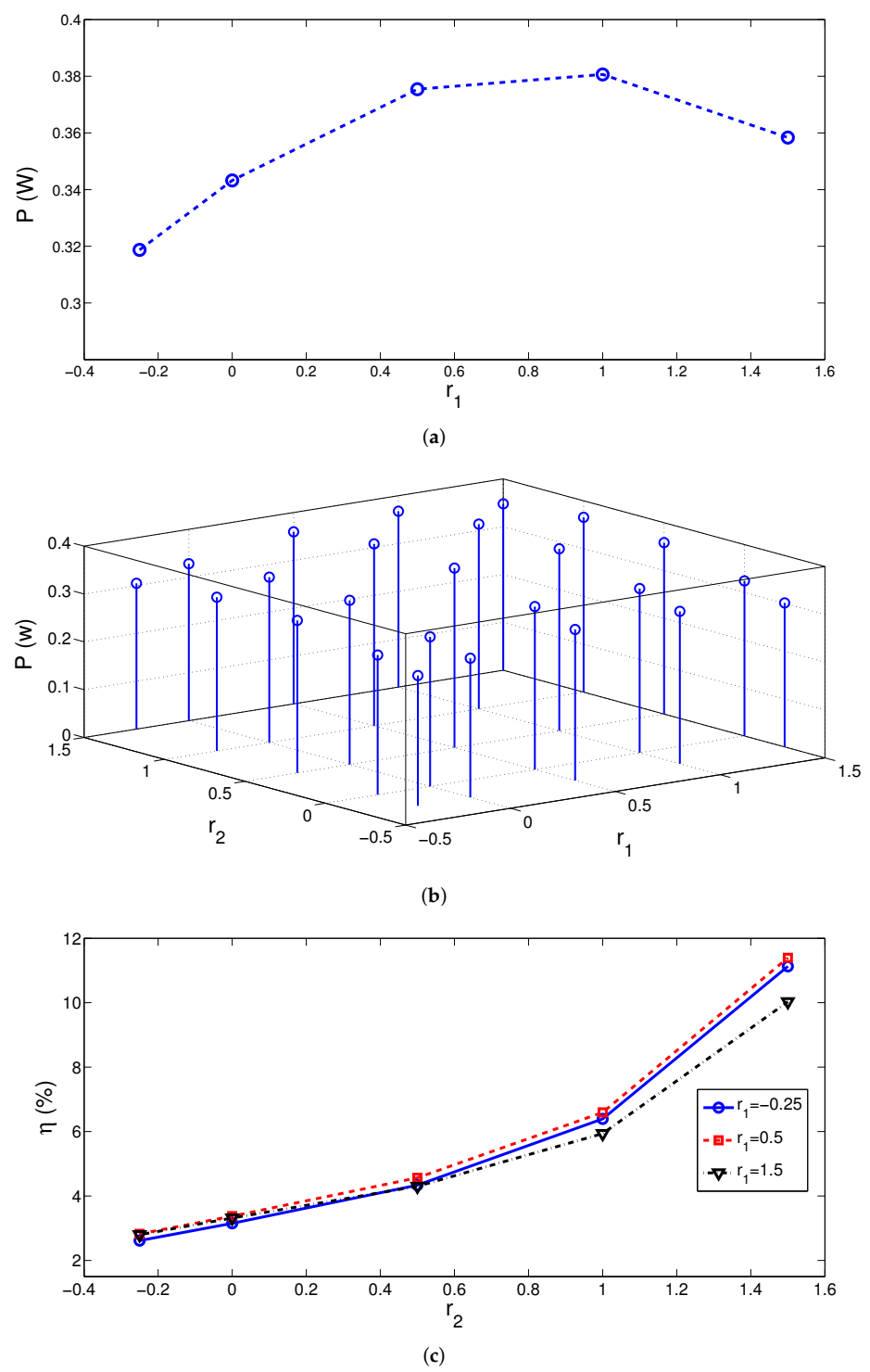
3. Results and Discussion
4. Conclusions
Author Contributions
Funding
Institutional Review Board Statement
Informed Consent Statement
Conflicts of Interest
Abbreviations
| A | pellet cross-sectional area, (m) |
| a | length of corrugation, (m) |
| E | electric field intensity vector, (V/m) |
| H | channel height, (m) |
| h | local heat transfer coefficient, (W/m·K) |
| h | height of corrugation, (m) |
| J | electric current density vector, (A/m) |
| k | thermal conductivity, (W/m·K) |
| L | channel length, (m) |
| L | module length, (m) |
| N | number of corrugated waves |
| n | unit normal vector |
| Nu | Nusselt number |
| p | pressure, (Pa) |
| P | power output, (W) |
| Pr | Prandtl number |
| R | internal resistance, () |
| R | load resistance, () |
| Re | Reynolds number |
| T | temperature, (K) |
| u, v, w | x-y,z velocity components, (m/s) |
| V | voltage, (V) |
| W | channel width, (m) |
| x, y, z | Cartesian coordinates, (m) |
| ZT | figure of merit |
| Greek Characters | |
| nanofluid thermal diffusivity, (m/s) | |
| Seeback coefficient, (V/K) | |
| dynamic viscosity, (Pa·s) | |
| kinematic viscosity, (m/s) | |
| density of the fluid, (kg/m) | |
| electrical conductivity, (S/m) | |
| solid volume fraction | |
| efficiency | |
| Subscripts | |
| c | cold wall |
| h | hot wall |
| m | average |
| nf | nanofluid |
References
- Pourkiaei, S.M.; Ahmadi, M.H.; Sadeghzadeh, M.; Moosavi, S.; Pourfayaz, F.; Chen, L.; Yazdi, M.A.P.; Kumar, R. Thermoelectric cooler and thermoelectric generator devices: A review of present and potential applications, modeling and materials. Energy 2019, 186, 115849. [Google Scholar] [CrossRef]
- Karthick, K.; Suresh, S.; Hussain, M.M.M.; Ali, H.M.; Kumar, C.S. Evaluation of solar thermal system configurations for thermoelectric generator applications: A critical review. Sol. Energy 2019, 188, 111–142. [Google Scholar] [CrossRef]
- Irshad, K.; Habib, K.; Saidur, R.; Kareem, M.; Saha, B.B. Study of thermoelectric and photovoltaic facade system for energy efficient building development: A review. J. Clean. Prod. 2019, 209, 1376–1395. [Google Scholar] [CrossRef]
- Weigand, B.; Spring, S. Multiple jet impingement—A review. Heat Transf. Res. 2011, 42, 101–142. [Google Scholar] [CrossRef]
- Krishan, G.; Aw, K.C.; Sharma, R.N. Synthetic jet impingement heat transfer enhancement—A review. Appl. Therm. Eng. 2019, 149, 1305–1323. [Google Scholar] [CrossRef]
- Nadda, R.; Kumar, A.; Maithani, R. Efficiency improvement of solar photovoltaic/solar air collectors by using impingement jets: A review. Renew. Sustain. Energy Rev. 2018, 93, 331–353. [Google Scholar] [CrossRef]
- Chen, Y.; Ma, C.; Qin, M.; Li, Y. Theoretical study on impingement heat transfer with single-phase free-surface slot jets. Int. J. Heat Mass Transf. 2005, 48, 3381–3386. [Google Scholar] [CrossRef]
- Tepe, A.Ü.; Yetişken, Y.; Uysal, Ü.; Arslan, K. Experimental and numerical investigation of jet impingement cooling using extended jet holes. Int. J. Heat Mass Transf. 2020, 158, 119945. [Google Scholar] [CrossRef]
- Aldabbagh, L.B.Y.; Mohamad, A.A. A three-dimensional numerical simulation of impinging jet arrays on a moving plate. Int. J. Heat Mass Transf. 2009, 52, 4894–4900. [Google Scholar] [CrossRef]
- Chattopadhyay, H.; Saha, S.K. Turbulent flow and heat transfer from a slot jet impinging on a moving plate. Int. J. Heat Fluid Flow 2003, 24, 685–697. [Google Scholar] [CrossRef]
- Chiriac, V.A.; Ortega, A. A numerical study of the unsteady flow and heat transfer in a transitional confined slot jet impinging on an isothermal surface. Int. J. Heat Mass Transf. 2002, 45, 1237–1248. [Google Scholar] [CrossRef]
- Koseoglu, M.F.; Baskaya, S. The role of jet inlet geometry in impinging jet heat transfer, modeling and experiments. Int. J. Therm. Sci. 2010, 49, 1417–1426. [Google Scholar] [CrossRef]
- Rehman, M.M.U.; Qu, Z.; Fu, R.; Xu, H. Numerical study on free-surface jet impingement cooling with nanoencapsulated phase-change material slurry and nanofluid. Int. J. Heat Mass Transf. 2017, 109, 312–325. [Google Scholar] [CrossRef]
- Nakharintr, L.; Naphon, P. Magnetic field effect on the enhancement of nanofluids heat transfer of a confined jet impingement in mini-channel heat sink. Int. J. Heat Mass Transf. 2017, 110, 753–759. [Google Scholar] [CrossRef]
- Selimefendigil, F.; Öztop, H.F. Pulsating nanofluids jet impingement cooling of a heated horizontal surface. Int. J. Heat Mass Transf. 2014, 69, 54–65. [Google Scholar] [CrossRef]
- Ahmadi, M.H.; Ghazvini, M.; Sadeghzadeh, M.; Nazari, M.A.; Ghalandari, M. Utilization of hybrid nanofluids in solar energy applications: A review. Nano-Struct. Nano-Objects 2019, 20, 100386. [Google Scholar] [CrossRef]
- Arshad, W.; Ali, H.M. Graphene nanoplatelets nanofluids thermal and hydrodynamic performance on integral fin heat sink. Int. J. Heat Mass Transf. 2017, 107, 995–1001. [Google Scholar] [CrossRef]
- Hamzah, M.H.; Sidik, N.A.C.; Ken, T.L.; Mamat, R.; Najafi, G. Factors affecting the performance of hybrid nanofluids: A comprehensive review. Int. J. Heat Mass Transf. 2017, 115, 630–646. [Google Scholar] [CrossRef]
- Kasaeian, A.; Daneshazarian, R.; Mahian, O.; Kolsi, L.; Chamkha, A.J.; Wongwises, S.; Pop, I. Nanofluid flow and heat transfer in porous media: A review of the latest developments. Int. J. Heat Mass Transf. 2017, 107, 778–791. [Google Scholar] [CrossRef]
- Mohammed, K.A.; Talib, A.A.; Nuraini, A.; Ahmed, K. Review of forced convection nanofluids through corrugated facing step. Renew. Sustain. Energy Rev. 2017, 75, 234–241. [Google Scholar] [CrossRef]
- Pordanjani, A.H.; Aghakhani, S.; Afrand, M.; Mahmoudi, B.; Mahian, O.; Wongwises, S. An updated review on application of nanofluids in heat exchangers for saving energy. Energy Convers. Manag. 2019, 198, 111886. [Google Scholar] [CrossRef]
- Sahin, A.Z.; Uddin, M.A.; Yilbas, B.S.; Al-Sharafi, A. Performance enhancement of solar energy systems using nanofluids: An updated review. Renew. Energy 2020, 145, 1126–1148. [Google Scholar] [CrossRef]
- Sajid, M.U.; Ali, H.M. Recent advances in application of nanofluids in heat transfer devices: A critical review. Renew. Sustain. Energy Rev. 2019, 103, 556–592. [Google Scholar] [CrossRef]
- Qiu, L.; Zhu, N.; Feng, Y.; Michaelides, E.E.; Żyła, G.; Jing, D.; Zhang, X.; Norris, P.M.; Markides, C.N.; Mahian, O. A review of recent advances in thermophysical properties at the nanoscale: From solid state to colloids. Phys. Rep. 2020, 843, 1–81. [Google Scholar] [CrossRef]
- Taherian, H.; Alvarado, J.L.; Languri, E.M. Enhanced thermophysical properties of multiwalled carbon nanotubes based nanofluids. Part 1: Critical review. Renew. Sustain. Energy Rev. 2018, 82, 4326–4336. [Google Scholar] [CrossRef]
- Yang, L.; Jiang, W.; Ji, W.; Mahian, O.; Bazri, S.; Sadri, R.; Badruddin, I.A.; Wongwises, S. A review of heating/cooling processes using nanomaterials suspended in refrigerants and lubricants. Int. J. Heat Mass Transf. 2020, 153, 119611. [Google Scholar] [CrossRef]
- Ambreen, T.; Kim, M.H. Influence of particle size on the effective thermal conductivity of nanofluids: A critical review. Appl. Energy 2020, 264, 114684. [Google Scholar] [CrossRef]
- Bahiraei, M.; Heshmatian, S. Graphene family nanofluids: A critical review and future research directions. Energy Convers. Manag. 2019, 196, 1222–1256. [Google Scholar] [CrossRef]
- Liang, G.; Mudawar, I. Review of single-phase and two-phase nanofluid heat transfer in macro-channels and micro-channels. Int. J. Heat Mass Transf. 2019, 136, 324–354. [Google Scholar] [CrossRef]
- Li, Q.; Xuan, Y.; Yu, F. Experimental investigation of submerged single jet impingement using Cu-water nanofluid. Appl. Therm. Eng. 2012, 36, 426–433. [Google Scholar] [CrossRef]
- Mahdavi, M.; Sharifpur, M.; Meyer, J.P.; Chen, L. Thermal analysis of a nanofluid free jet impingement on a rotating disk using volume of fluid in combination with discrete modelling. Int. J. Therm. Sci. 2020, 158, 106532. [Google Scholar] [CrossRef]
- Jajja, S.A.; Ali, W.; Ali, H.M.; Ali, A.M. Water cooled minichannel heat sinks for microprocessor cooling: Effect of fin spacing. Appl. Therm. Eng. 2014, 64, 76–82. [Google Scholar] [CrossRef]
- Manca, O.; Mesolella, P.; Nardini, S.; Ricci, D. Numerical study of a confined slot impinging jet with nanofluids. Nanoscale Res. Lett. 2011, 6, 188. [Google Scholar] [CrossRef] [PubMed] [Green Version]
- Arshad, W.; Ali, H.M. Experimental investigation of heat transfer and pressure drop in a straight minichannel heat sink using TiO2 nanofluid. Int. J. Heat Mass Transf. 2017, 110, 248–256. [Google Scholar] [CrossRef]
- Selimefendigil, F.; Oztop, H.F. Jet impingement cooling and optimization study for a partly curved isothermal surface with CuO-water nanofluid. Int. Commun. Heat Mass Transf. 2017, 89, 211–218. [Google Scholar] [CrossRef]
- Naphon, P.; Nakharintr, L.; Wiriyasart, S. Continuous nanofluids jet impingement heat transfer and flow in a micro-channel heat sink. Int. J. Heat Mass Transf. 2018, 126, 924–932. [Google Scholar] [CrossRef]
- Mohammadpour, J.; Lee, A. Investigation of nanoparticle effects on jet impingement heat transfer: A review. J. Mol. Liq. 2020, 316, 113819. [Google Scholar] [CrossRef]
- Kramer, L.R.; Mara, A.L.O.; Souza, S.S.; Ando, O.H. Analytical and numerical study for the determination of a thermoelectric generator’s internal resistance. Energies 2019, 12, 3053. [Google Scholar] [CrossRef] [Green Version]
- Kim, C.N. Development of a numerical method for the performance analysis of thermoelectric generators with thermal and electric contact resistance. Appl. Therm. Eng. 2018, 1305, 408–417. [Google Scholar] [CrossRef]
- Zuckerman, N.; Lior, N. Jet impingement heat transfer: Physics, correlations, and numerical modeling. Adv. Heat Transf. 2006, 39, 565–631. [Google Scholar]
- Sajjadi, H.; Delouei, A.A.; Izadi, M.; Mohebbi, R. Investigation of MHD natural convection in a porous media by double MRT lattice Boltzmann method utilizing MWCNT-Fe3O4/water hybrid nanofluid. Int. J. Heat Mass Transf. 2019, 132, 1087–1104. [Google Scholar] [CrossRef]
- Brinkman, H. The viscosity of concentrated suspensions and solutions. J. Chem. Phys. 1952, 20, 571–581. [Google Scholar] [CrossRef]
- Xue, Q. Model for thermal conductivity of carbon nanotube—Based composites. Physica B 2005, 368, 302–307. [Google Scholar] [CrossRef]
- COMSOL A.B. COMSOL Multiphysics v. 5.4; COMSOL: Stockholm, Sweden, 2018. [Google Scholar]
- Sharif, M.A. Heat transfer from an isothermally heated flat surface due to confined laminar twin oblique slot-jet impingement. J. Therm. Sci. Eng. Appl. 2015, 7. [Google Scholar] [CrossRef]
- Sahoo, D.; Sharif, M. Numerical modeling of slot-jet impingement cooling of a constant heat flux surface confined by a parallel wall. Int. J. Therm. Sci. 2004, 43, 877–887. [Google Scholar] [CrossRef]
- Chen, M.; Rosendahl, L.A.; Condra, T. A three-dimensional numerical model of thermoelectric generators in fluid power systems. Int. J. Heat Mass Transf. 2011, 54, 345–355. [Google Scholar] [CrossRef]


| Symbol | P Type Leg (BiTe) | N type leg (BiTe) | Electrode (Copper) | Ceramic (Alumina) | |
|---|---|---|---|---|---|
| Thermal conductivity | k (W/m K) | 1.6 | 1.6 | 400 | 27 |
| Electric conductivity | (S/m) | - | |||
| Seebeck coefficient | (V/K) | - | |||
| Heat capacity | C (J/kg K) | 154 | 154 | 385 | 900 |
| Density | (kg/m) | 7700 | 7700 | 8960 | 3900 |
| Property | Water | Single-Walled CNT |
|---|---|---|
| 997.1 | 2600 | |
| 4179 | 425 | |
| 0.61 | 6600 | |
| (kg/ms) | 8.55 | - |
| Coefficient | Value () | Value () |
|---|---|---|
| p00 | 0.3809 (0.3744, 0.3873) | 0.4233 (0.4172, 0.4293) |
| p10 | 0.04377 (0.0405, 0.04704) | 0.04445 (0.04136, 0.04754) |
| p01 | 0.04111 (0.03784, 0.04438) | 0.04174 (0.03866, 0.04483) |
| p20 | −0.01668 (−0.02091, −0.01246) | −0.01655 (−0.02054, −0.01256) |
| p11 | 0.007408 (0.00403, 0.01079) | 0.006836 (0.003646, 0.01003) |
| p02 | −0.0158 (−0.02002, −0.01157) | −0.01565 (−0.01963, −0.01166) |
| Coefficient | Value () | Value () |
|---|---|---|
| p00 | 4.814 (4.767, 4.861) | 4.981 (4.938, 5.025) |
| p10 | 0.09867 (0.07455, 0.1228) | 0.1542 (0.1323, 0.1762) |
| p01 | 0.2611 (0.237, 0.2852) | 0.2405 (0.2185, 0.2624) |
| p20 | −0.05066 (−0.0818, −0.01951) | −0.07421 (−0.1025, −0.04591) |
| p11 | 0.01082 (−0.01409, 0.03574) | 0.01314 (−0.009496, 0.03578) |
| p02 | −0.09839 (−0.1295, −0.06724) | −0.0921 (−0.1204, −0.0638) |
| Fit Name | Value-Power () | Value-Power () |
|---|---|---|
| SSE | 0.0003231 | 0.0002882 |
| R-square | 0.9946 | 0.9953 |
| RMSE | 0.005685 | 0.005368 |
| Fit Name | Value-Efficiency () | Value-Efficiency () |
| SSE | 0.01758 | 0.01452 |
| R-square | 0.9865 | 0.9894 |
| RMSE | 0.04193 | 0.0381 |
Publisher’s Note: MDPI stays neutral with regard to jurisdictional claims in published maps and institutional affiliations. |
© 2021 by the authors. Licensee MDPI, Basel, Switzerland. This article is an open access article distributed under the terms and conditions of the Creative Commons Attribution (CC BY) license (http://creativecommons.org/licenses/by/4.0/).
Share and Cite
Selimefendigil, F.; Oztop, H.F.; Sheremet, M.A. Thermoelectric Generation with Impinging Nano-Jets. Energies 2021, 14, 492. https://doi.org/10.3390/en14020492
Selimefendigil F, Oztop HF, Sheremet MA. Thermoelectric Generation with Impinging Nano-Jets. Energies. 2021; 14(2):492. https://doi.org/10.3390/en14020492
Chicago/Turabian StyleSelimefendigil, Fatih, Hakan F. Oztop, and Mikhail A. Sheremet. 2021. "Thermoelectric Generation with Impinging Nano-Jets" Energies 14, no. 2: 492. https://doi.org/10.3390/en14020492
APA StyleSelimefendigil, F., Oztop, H. F., & Sheremet, M. A. (2021). Thermoelectric Generation with Impinging Nano-Jets. Energies, 14(2), 492. https://doi.org/10.3390/en14020492