Intelligent Starting Current-Based Fault Identification of an Induction Motor Operating under Various Power Quality Issues

 ,
,  and
and
Abstract
1. Introduction
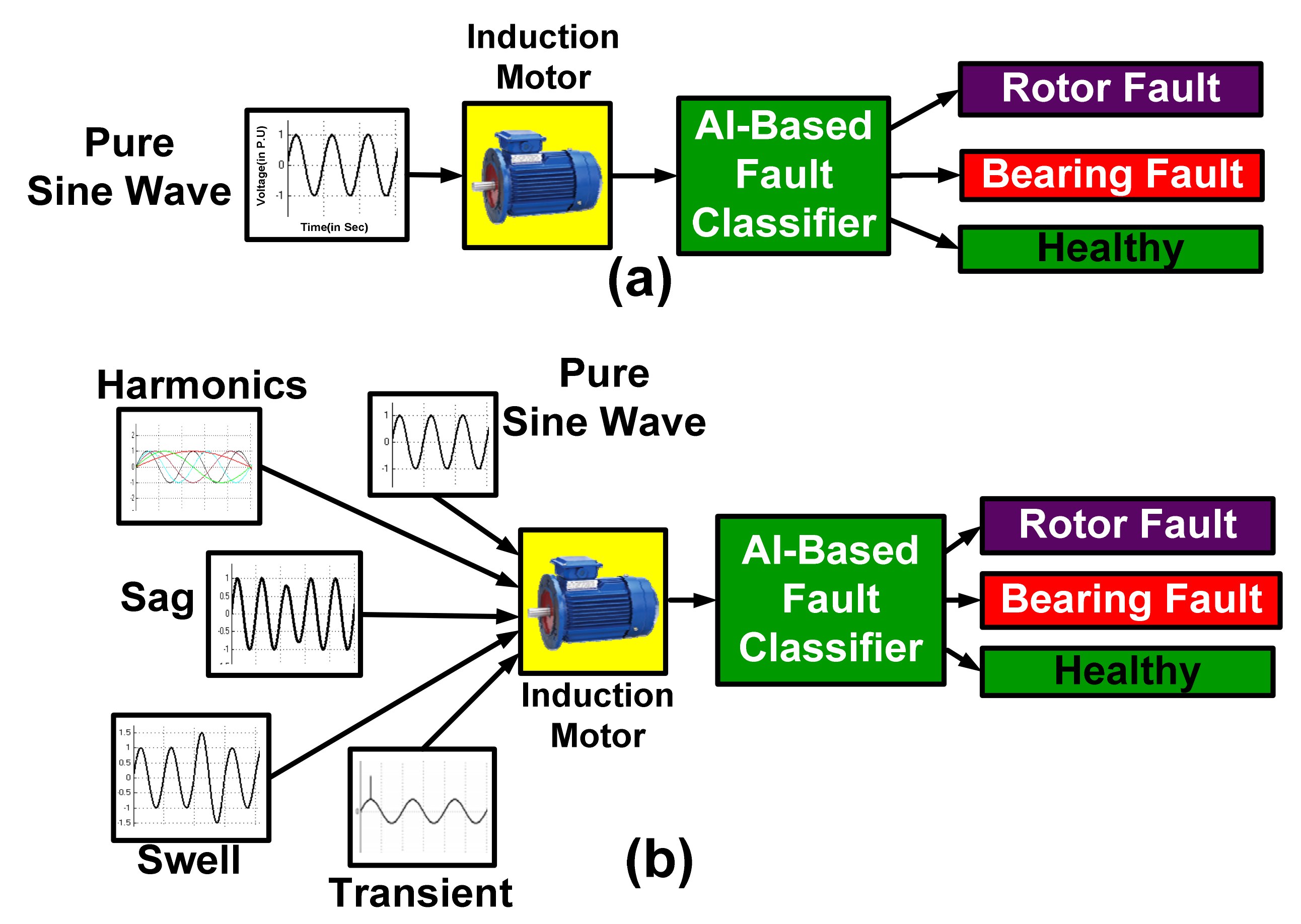
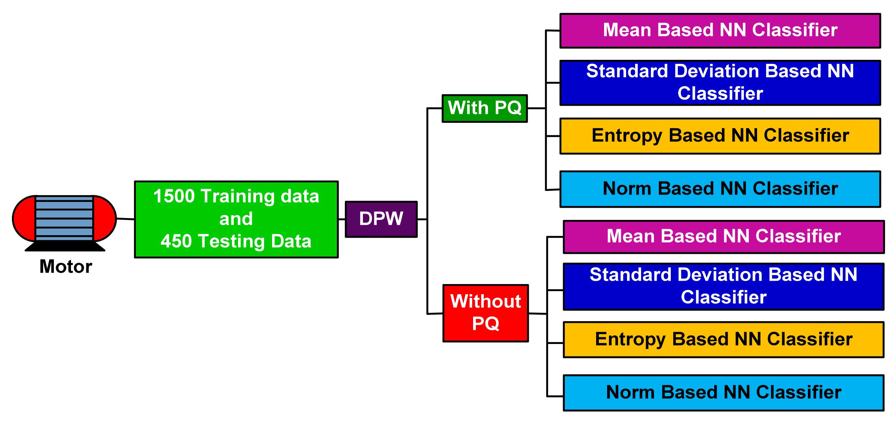
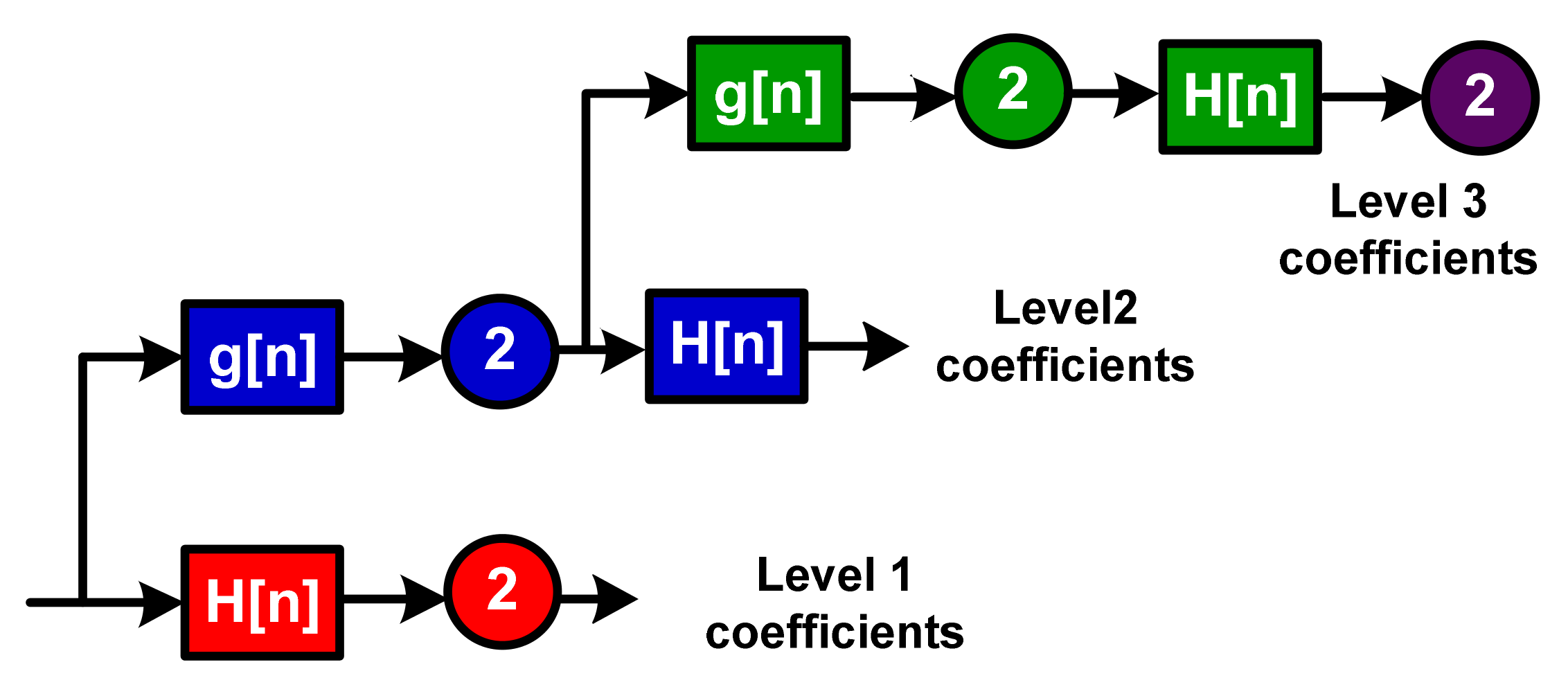
2. Theoretical Background, Materials and Methods
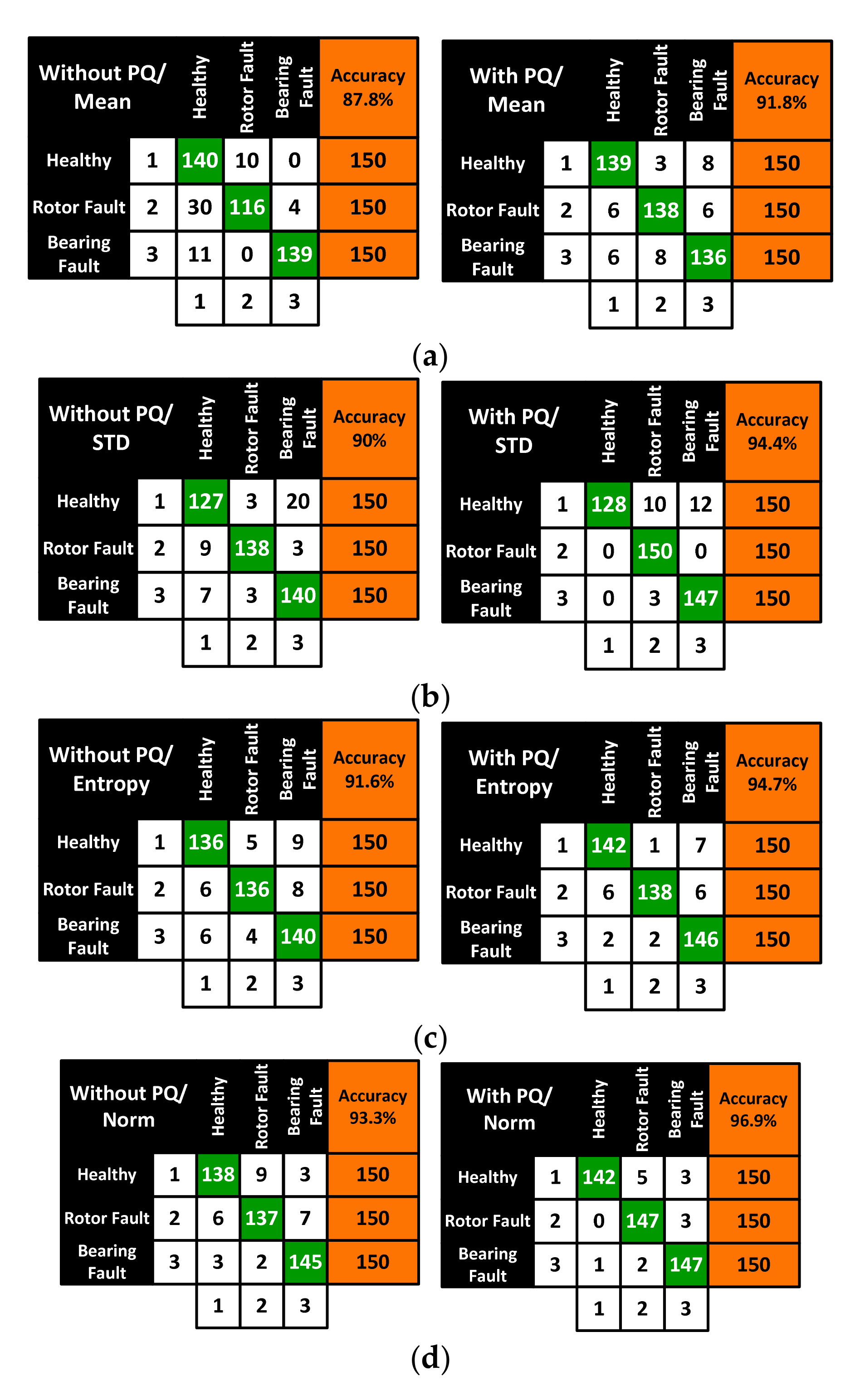
3. Results
4. Conclusions
Author Contributions
Funding
Conflicts of Interest
References
- Liang, X.; Ilochonwu, O. Induction Motor Starting in Practical Industrial Applications. Industry Applications. IEEE Trans. Ind. Appl. 2018, 47, 271–280. [Google Scholar] [CrossRef]
- Romero-Troncoso, R.J.; Saucedo-Gallaga, R.; Cabal-Yepez, E.; Garcia-Perez, A.; Osornio-Rios, R.A.; Alvarez-Salas, R.; Miranda-Vidales, H.; Huber, N. FPGA-based online detection of multiple combined faults in induction motors through information entropy and fuzzy inference. IEEE Trans. Ind. Electron. 2011, 58, 5263–5270. [Google Scholar] [CrossRef]
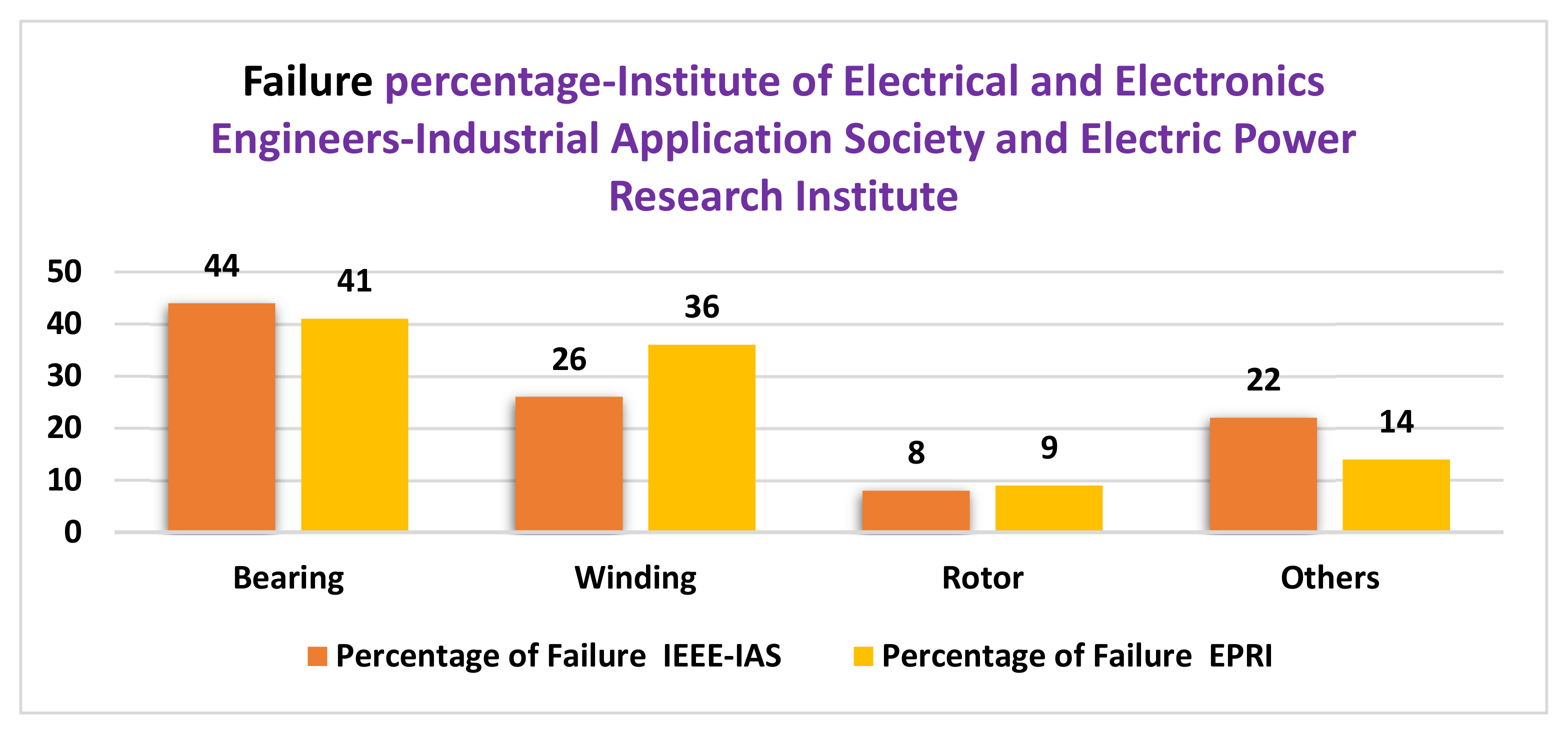
- Bonnett, A.H.; Soukup, G.C. Cause and analysis of stator and rotor failures in three-phase squirrel-cage induction motors. IEEE Trans. Ind. Appl. 1992, 28, 921–937. [Google Scholar] [CrossRef]
- Bonnett, A.H.; Soukup, G.C. Analysis of rotor failures in squirrel-cage induction motors. IEEE Trans. Ind. Appl. 1998, 24, 1124–1130. [Google Scholar] [CrossRef]
- Siyambalapitiya, D.J.T.; McLaren, P.G.; Acarnley, P.P. A rotor condition monitor for squirrel-cage induction machines. IEEE Trans. Ind. Appl. 1987, IA-23, 334–340. [Google Scholar] [CrossRef]
- Mehrjou, M.R.; Mariun, N.; Marhaban, M.H.; Misron, N. Rotor fault condition monitoring techniques for squirrel-cage inductionmachine—A. review. Mech. Syst. Signal Process. 2011, 25, 2827–2848. [Google Scholar] [CrossRef]
- Curcuru’, G.; Cocconcelli, M.; Immovilli, F.; Rubini, R. On thedetection of distributed roughness on ball bearings via stator currentenergy: Experimental results. Diagnostyka 2009, 51, 17–21. [Google Scholar]
- Ibrahim, A.; El Badaoui, M.; Guillet, F.; Youssef, W. Electrical signalsanalysis of an asynchronous motor for bearing fault detection. In Proceedings of the IECON 2006-32nd Annual Conference on IEEE Industrial Electronics, Paris, France, 6–10 November 2006; pp. 4975–4980. [Google Scholar]
- Sun, L.; Xu, B. An improvement of stator current based detectionof bearing fault in induction motors. In Proceedings of the 2007 IEEE Industry Applications Annual Meeting, New Orleans, LA, USA, 23–27 September 2007; pp. 2277–2281. [Google Scholar]
- Blodt, M.; Chabert, M.; Regnier, J.; Faucher, J. Mechanical load faultdetection in induction motors by stator current time–frequency analysis. IEEE Trans. Ind. Appl. 2006, 42, 1454–1463. [Google Scholar] [CrossRef]
- Seera, M.; Lim, C.P.; Nahavandi, S.; Loo, C.K. Condition monitoringof induction motors: A review and an application of an ensembleof hybrid intelligent models. Expert Syst. Appl. 2014, 41, 4891–4903. [Google Scholar] [CrossRef]
- Drif, M.; Cardoso, A.J.M. Stator fault diagnostics in squirrel cagethree-phase induction motor drives using the instantaneous active andreactive power signature analyses. IEEE Trans. Ind. Inf. 2014, 10, 1348–1360. [Google Scholar] [CrossRef]
- Sohani, A.; Shahverdian, M.H.; Sayyaadi, H.; Garcia, D.A. Impact of absolute and relative humidity on the performance of mono and poly crystalline silicon photovoltaics; applying artificial neural network. J. Clean. Prod. 2020, 276, 123016. [Google Scholar] [CrossRef]
- Majidi, N.M.; Heydari, A.; Groppi, D.; Cumo, F.; Garcia, D.A. Wind source potential assessment using Sentinel 1 satellite and a new forecasting model based on machine learning: A case study Sardinia islands. Renew. Energy 2020, 155, 212–224. [Google Scholar] [CrossRef]
- Antonino-Daviu, J.; Riera-Guasp, M.; Roger-Folch, J.; Martınez, G.F.; Peris, A. Application and optimization of the discrete wavelet transform for the detection of broken rotor bars in induction machines. Appl. Comput. Harmon. Anal. 2006, 21, 268–279. [Google Scholar] [CrossRef]
- Cho, H.C.; Knowles, J.; Fadali, M.S.; Lee, K.S. Fault Detection and Isolation of Induction Motors Using Recurrent Neural Networks and Dynamic Bayesian Modeling. IEEE Trans. Control Syst. Technol. 2010, 18, 430–437. [Google Scholar] [CrossRef]
- Su, H.; Chong, K.T. Induction machine condition monitoring using neural network modelling. IEEE Trans. Ind. Electron. 2007, 54, 241–249. [Google Scholar] [CrossRef]
- El Bouchikhi, E.H.; Choqueuse, V.; Benbouzid, M. Induction machine faults detection using stator current parametric spectral estimation. Mech. Syst. Signal Process. 2015, 52–53, 447–464. [Google Scholar] [CrossRef]
- He, Q. Vibration signal classification by wavelet packet energy flow manifold learning. J. Sound Vib. 2013, 332, 1881–1894. [Google Scholar] [CrossRef]
- Duraisamy, V.; Devarajan, N.; Somesundareswari, D.; Sivanandam, S.N. Modified back propagation algorithm for incipient fault detection in three phase induction motor. Model. Meas. Control 2006, 79, 15–25. [Google Scholar]
- Wang, Z.-X.; Chang, C.S.; German, X.; Tan, W.W. Online fault detection of induction motors using independent component analysis and fuzzy neural network. In Proceedings of the 8th International Conference on Advances in Power System Control, Operation and Management (APSCOM 2009), London, UK, 8–11 November 2009; p. 321. [Google Scholar]
- Chua, T.W.; Tan, W.W.; Wang, Z.-X.; Chang, C.S. Hybrid time-frequency domain analysis for inverter-fed induction motor fault detection. In Proceedings of the IEEE International Symposium on Industrial Electronics (ISIE), Bari, Italy, 4 July 2010; pp. 1633–1638. [Google Scholar]
- Garcia-Ramirez, A.G.; Osornio-Rios, R.A.; Garcia-Perez, A.; Romero-Troncoso, R.D.J. FPGA-based smart-sensor for fault detection in VSD-fed induction motors. In Proceedings of the 2013 9th IEEE International Symposium on Diagnostics for Electric Machines, Power Electronics and Drives (SDEMPED), Valencia, Spain, 27–30 August 2013; pp. 233–240. [Google Scholar]


| S. No | Name of the Parameters | Value |
|---|---|---|
| 1 | Rated power | 70 W |
| 2 | Rated current | 0.34 A |
| 3 | No of poles | 4 |
| 4 | No of slots | 36 |
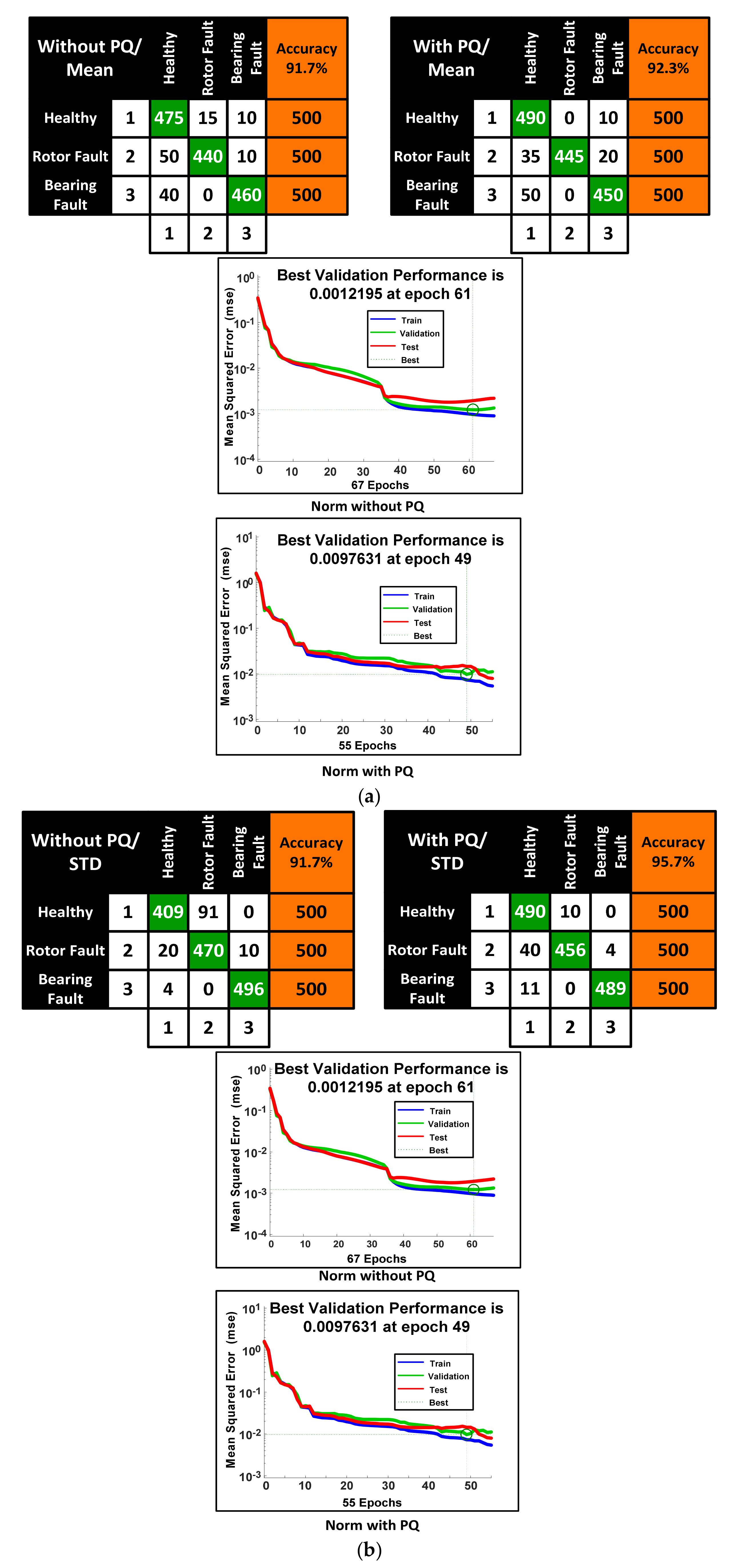
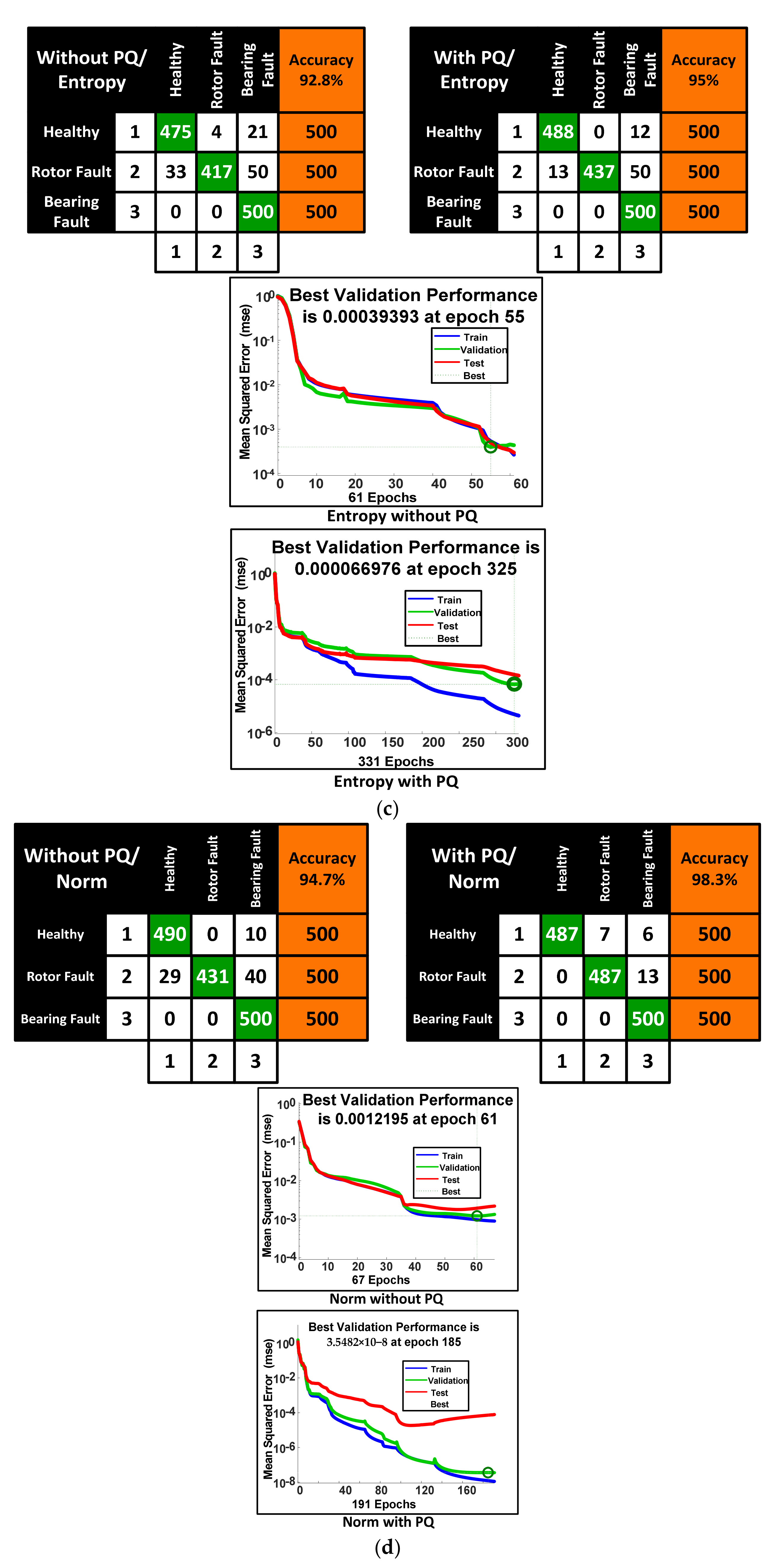
| Parameters | Without PQ | With PQ | ||||||
|---|---|---|---|---|---|---|---|---|
| Mean | Std | Entropy | Norm | Mean | Std | Entropy | Norm | |
| Total No of samples | 1500 | 1500 | 1500 | 1500 | 1500 | 1500 | 1500 | 1500 |
| Correctly Classified | 1375 | 1375 | 1392 | 1421 | 1385 | 1435 | 1425 | 1474 |
| Total No of 1 | 500 | 500 | 500 | 500 | 500 | 500 | 500 | 500 |
| Total no of 2 | 500 | 500 | 500 | 500 | 500 | 500 | 500 | 500 |
| Total no of 3 | 500 | 500 | 500 | 500 | 500 | 500 | 500 | 500 |
| Total No of 1 | 565 | 433 | 508 | 519 | 575 | 541 | 501 | 487 |
| Total no of 2 | 455 | 561 | 421 | 431 | 445 | 466 | 437 | 494 |
| Total no of 3 | 480 | 506 | 571 | 550 | 480 | 493 | 562 | 519 |
| Wrongly Classified | 125 | 125 | 108 | 79 | 115 | 65 | 75 | 26 |
| 1 as 2 | 15 | 91 | 4 | 0 | 0 | 10 | 0 | 7 |
| 1 as 3 | 10 | 0 | 21 | 10 | 10 | 0 | 12 | 6 |
| 2 as 1 | 50 | 20 | 33 | 29 | 35 | 40 | 13 | 0 |
| 2 as 3 | 10 | 10 | 50 | 40 | 20 | 4 | 50 | 13 |
| 3 as 1 | 40 | 4 | 0 | 0 | 50 | 11 | 0 | 0 |
| 3 as 2 | 0 | 0 | 0 | 0 | 0 | 0 | 0 | 0 |
| Total % Accuracy | 91.7% | 91.7% | 92.8% | 94.7% | 92.3% | 95.7% | 95.0% | 98.3% |
| Parameters | Without PQ | With PQ | ||||||
|---|---|---|---|---|---|---|---|---|
| Mean | Std | Entropy | Norm | Mean | Std | Entropy | Norm | |
| Total No of samples | 450 | 450 | 450 | 450 | 450 | 450 | 450 | 450 |
| Correctly Classified | 395 | 405 | 412 | 420 | 413 | 425 | 426 | 436 |
| Total No of 1 | 150 | 150 | 150 | 150 | 150 | 150 | 150 | 150 |
| Total no of 2 | 150 | 150 | 150 | 150 | 150 | 150 | 150 | 150 |
| Total no of 3 | 150 | 150 | 150 | 150 | 150 | 150 | 150 | 150 |
| Total No of 1 | 181 | 143 | 148 | 147 | 151 | 128 | 150 | 143 |
| Total no of 2 | 126 | 144 | 145 | 148 | 149 | 163 | 141 | 154 |
| Total no of 3 | 143 | 166 | 161 | 157 | 158 | 162 | 161 | 155 |
| Wrongly Classified | 55 | 45 | 38 | 30 | 37 | 25 | 24 | 14 |
| 1 as 2 | 10 | 3 | 5 | 9 | 3 | 10 | 1 | 5 |
| 1 as 3 | 0 | 20 | 9 | 3 | 8 | 12 | 7 | 3 |
| 2 as 1 | 30 | 9 | 6 | 6 | 6 | 0 | 6 | 0 |
| 2 as 3 | 4 | 3 | 8 | 7 | 6 | 0 | 6 | 3 |
| 3 as 1 | 11 | 7 | 6 | 3 | 6 | 0 | 2 | 1 |
| 3 as 2 | 0 | 3 | 4 | 2 | 8 | 3 | 2 | 2 |
| Total % Accuracy | 87.8% | 90.0% | 91.6% | 93.3% | 91.8% | 94.4% | 94.7% | 96.9% |
| S.No. | Techniques | Accuracy (%) | |
|---|---|---|---|
| Without PQ | With PQ | ||
| 1 | Proposed technique | 94.7 | 98.3 |
| 2 | Feed forward neural network (FNN) method [21] | 93.3 | 94 |
| 3 | Component analysis method [22] | 66.6 | - |
| 4 | Smart sensor method [23] | 85.8 | 88.8 |
| 5 | Field programmable gate array (FPGA)-based method | 89 | 90.4 |
Publisher’s Note: MDPI stays neutral with regard to jurisdictional claims in published maps and institutional affiliations. |
© 2021 by the authors. Licensee MDPI, Basel, Switzerland. This article is an open access article distributed under the terms and conditions of the Creative Commons Attribution (CC BY) license (http://creativecommons.org/licenses/by/4.0/).
Share and Cite
Ganesan, S.; David, P.W.; Balachandran, P.K.; Samithas, D. Intelligent Starting Current-Based Fault Identification of an Induction Motor Operating under Various Power Quality Issues. Energies 2021, 14, 304. https://doi.org/10.3390/en14020304
Ganesan S, David PW, Balachandran PK, Samithas D. Intelligent Starting Current-Based Fault Identification of an Induction Motor Operating under Various Power Quality Issues. Energies. 2021; 14(2):304. https://doi.org/10.3390/en14020304
Chicago/Turabian StyleGanesan, Sakthivel, Prince Winston David, Praveen Kumar Balachandran, and Devakirubakaran Samithas. 2021. "Intelligent Starting Current-Based Fault Identification of an Induction Motor Operating under Various Power Quality Issues" Energies 14, no. 2: 304. https://doi.org/10.3390/en14020304
APA StyleGanesan, S., David, P. W., Balachandran, P. K., & Samithas, D. (2021). Intelligent Starting Current-Based Fault Identification of an Induction Motor Operating under Various Power Quality Issues. Energies, 14(2), 304. https://doi.org/10.3390/en14020304