Article

Opposite Triangle Carrier with SVPWM for Common-Mode Voltage Reduction in Dual Three Phase Motor Drives

Department of Electrical Engineering, Pusan National University, Busan 46241, Korea
*
Author to whom correspondence should be addressed.
Energies 2021, 14(2), 282; https://doi.org/10.3390/en14020282
Submission received: 23 November 2020 / Revised: 29 December 2020 / Accepted: 4 January 2021 / Published: 6 January 2021
(This article belongs to the Special Issue Advances in Electric Drives and Power Electronics Fields)

Abstract

:
The common-mode voltage (CMV) generated by the switching operation of the pulse width modulation (PWM) inverter leads to bearing failure and electromagnetic interference (EMI) noises. To reduce the CMV, it is necessary to reduce the magnitude of dv/dt and change the frequency of the CMV. In this paper, the range of the CMV is reduced by using opposite triangle carrier for ABC and XYZ winding group, and the change in frequency in the CMV is reduced by equalizing the dwell time of the zero voltage vector on ABC and XYZ winding group of dual three phase motor.

1. Introduction

Dual three phase motors have advantages such as reduced phase current rating, reduced torque ripple, high torque density, and improved reliability during fault. In particular, the dual three phase motor can easily be operated with the three phase inverter module, and is applied to propulsion systems such as trains, and ship and air transportation [1,2,3,4,5,6,7,8].
For dual three phase motor, the two sets of stator winding are arranged as the symmetric (0° or 60°) or the asymmetric (30°) structure. Asymmetric dual three phase motors shown in Figure 1 are preferred over symmetric dual three phase motors, because they can cancel the 6th order component torque ripple [4,5,9].
Pulse width modulation (PWM) inverters are widely used to enhance the variable speed control performance and efficiency of motors. The PWM operation causes a change of potential difference between stator neutral point and midpoint of the dc-link voltage, which is called common-mode voltage (CMV). Since the CMV causes bearing failure and undesirable electromagnetic interference (EMI), the reduction of the CMV is essential for improving the stability and life span of the motor. The motor shaft voltage is similar to the CMV, and the dv/dt current flows through bearing when the shaft voltage changes. The key factors to reduce the CMV are reduction of the magnitude of dv/dt and change frequency [7,8,10,11,12].
The method for reducing CMV in the inverter system is classified into hardware- and software-based methods. The hardware method is to use passive and active common-mode filters [13,14]. However, this method increases both the size and cost of the system due to the additional common-mode filters installed at the inverter input side [13] or between the inverter and motor [14].
The software-based CMV reduction methods are implemented by manipulating the PWM pattern of the inverter system. In the three-phase two-level inverter system, CMV can be reduced by methods such as remote state PWM (RSPWM) [15], near state PWM (NSPWM) [16], active zero state PWM (AZSPWM) [17], and phase-shifted carrier PWM (PSC PWM) [18]. In three-phase multi-level inverter systems such as three-level NPC inverter [19], five-level ANPC inverter [20], and MMC system [21], CMV elimination methods were accomplished by using only the voltage vectors that do not generate CMV. Several studies have been conducted to reduce or remove CMV in multiphase two-level inverter systems [7,8,22,23,24,25,26]. The papers in [7,8,26] proposed an algorithm to reduce or remove CMV by using PWM method in dual three phase motor. The authors in [7] analyzed the characteristics of the CMV according to the carrier method in the dual three phase motor and reduced the change frequency of CMV using sawtooth carrier. In [8], CMV is eliminated by shifting the PWM signals within the cycle of the switching frequency. In [26], CMV is reduced without using zero voltage vector. However, the voltage utilization in [7,8] was low because the algorithm of these papers is based on sinusoidal PWM (SPWM) [27].
In this paper, a CMV reduction method is proposed using space vector PWM (SVPWM) with whole voltage vector in dual three phase motor, as in Figure 1. To reduce the range of the CMV, the opposite triangle carrier is applied to ABC and XYZ winding groups. The change frequency of the CMV is reduced by synchronizing the dwell time of the zero voltage vector on the ABC and XYZ winding groups. The validity of the proposed method is verified through experimental results.

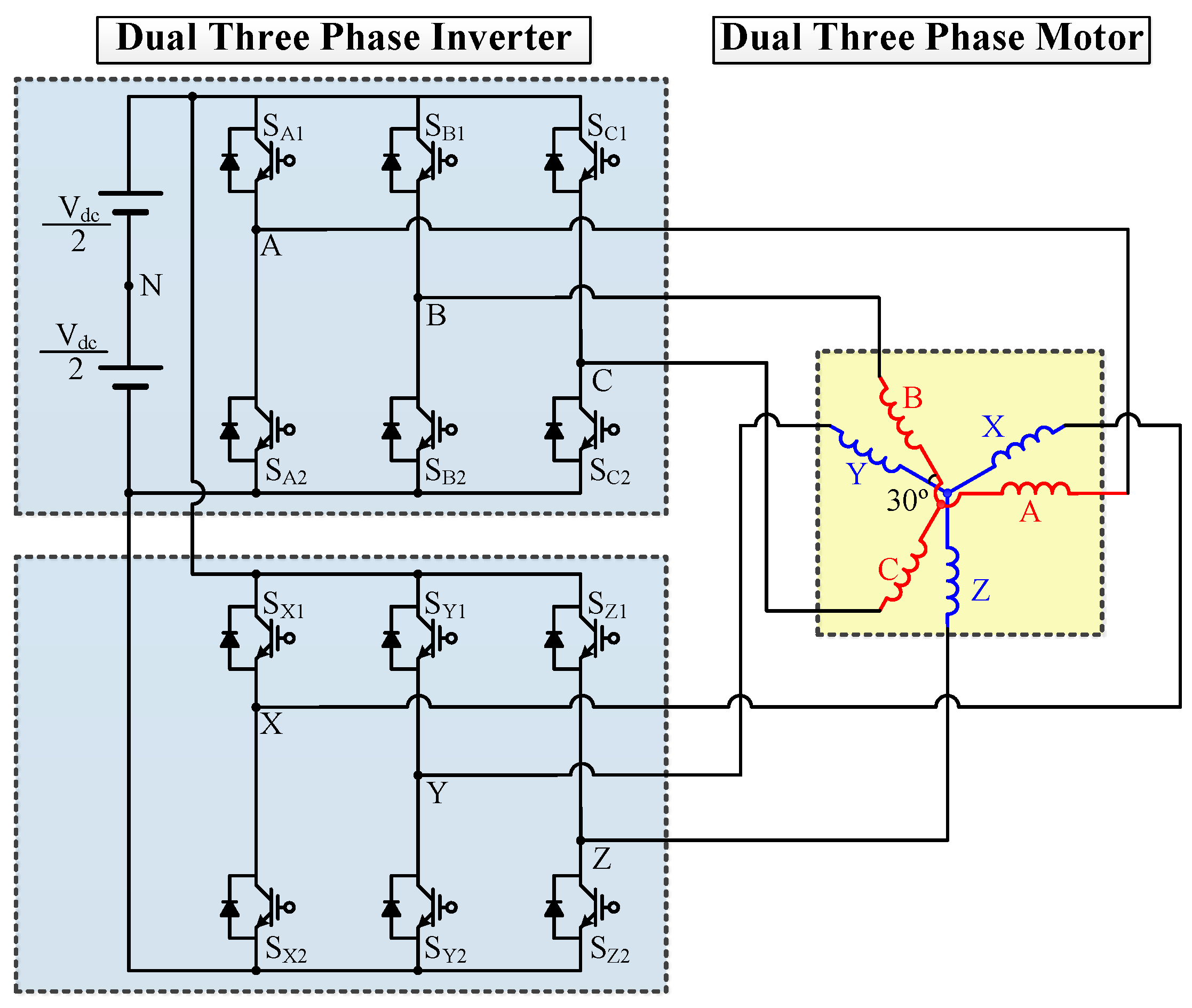
2. CMV in Dual Three Phase Motor

2.1. CMV in Dual Three Phase Motor

In three-phase two-level inverter, the pole voltage is Vdc/2 when the upper switch is On, and −Vdc/2 when the lower switch is On in each leg. The CMV of the three phase motor can be expressed as the average of the three phase pole voltages given by Equation (1).
Vcm_3ph = (VAN + VBN + VCN)/3
where VxN (x = A, B, C) is the pole voltage in each phase.
According to Equation (1) the CMV in the dual three-phase motor has a state of −Vdc/2, −Vdc/6, Vdc/6, and Vdc/2, based on the switching signals.
The CMV in each winding groups of the dual three phase motor has the same shape as a three-phase motor, and is expressed as Equation (2).
Vcm_ABC = (VAN + VBN + VCN)/3
Vcm_XYZ = (VXN + VYN + VZN)/3
where Vcm_ABC, Vcm_XYZ, and VxN (x = A, B, C, X, Y, and Z) are the CMV in ABC winding group, CMV in XYZ winding group, and pole voltage in phase x.
Similar to the three phase motor, the state of the CMV in each winding group of the dual three phase motor is −Vdc/2, −Vdc/6, Vdc/6, and Vdc/2. The CMV in dual three phase motor can be expressed as the average of the CMV in each winding group [8].
Vcm = (Vcm_ABC + Vcm_XYZ)/2
Hence, the state of the CMV in dual three phase motor is −Vdc/2, −Vdc/3, −Vdc/6, 0, Vdc/6, Vdc/3, and Vdc/2, as per Equation (3).

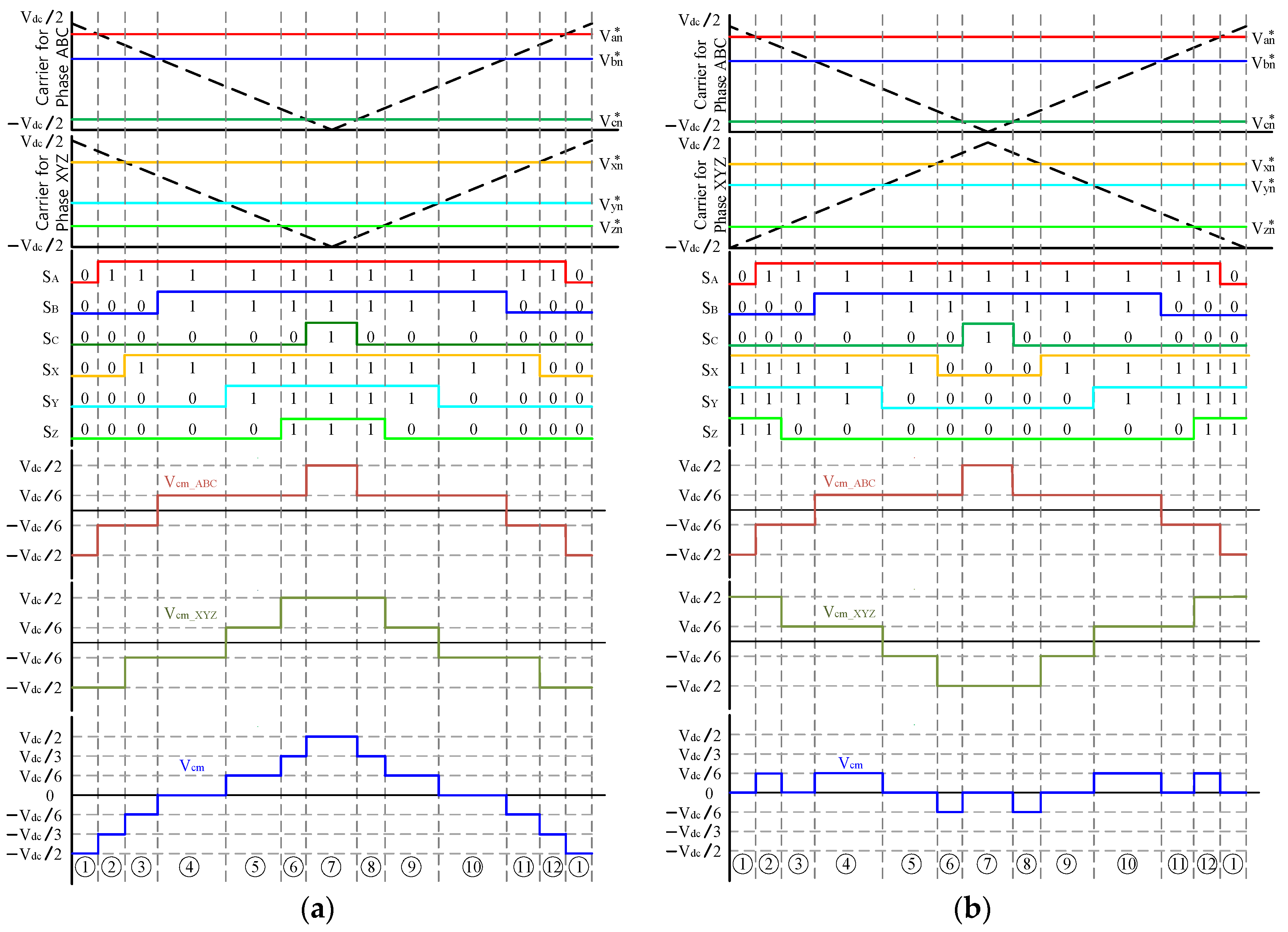
2.2. CMV According to the Carrier Method

Figure 2 shows the CMV characteristics according to the carrier method in the dual three phase motor. Figure 2a shows the CMV characteristics applied to the same triangle carrier waveforms on ABC and XYZ winding groups. Since the change of the CMV occurs at the intersection of the carrier and reference of pole voltage (Vxn*), the change frequency of the CMV during one switching cycle is 6 times in each winding group, and the state of the CMV in each winding group is −Vdc/2, −Vdc/6, Vdc/6, and Vdc/2. Therefore, the state of the CMV in the dual three phase motor is −Vdc/2, −Vdc/3, −Vdc/6, 0, Vdc/6, Vdc/3, and Vdc/2, and the change frequency of the CMV is 12 times according to Equation (3).
Figure 2b shows the CMV characteristics applied to the opposite triangle carrier waveforms on ABC and XYZ winding group. An explained above, the state of the CMV in each winding group is −Vdc/2, −Vdc/6, Vdc/6, and Vdc/2. However, since the CMV waveforms of ABC and XYZ has an opposite form, the state of the CMV in the dual three phase motor is −Vdc/6, 0, Vdc/6, because the magnitude of CMV in ABC and XYZ winding group offset each other. However, the change frequency of the CMV in dual three phase motor is 12 times, which is equal to the change frequency of the CMV when same triangle carrier is used.

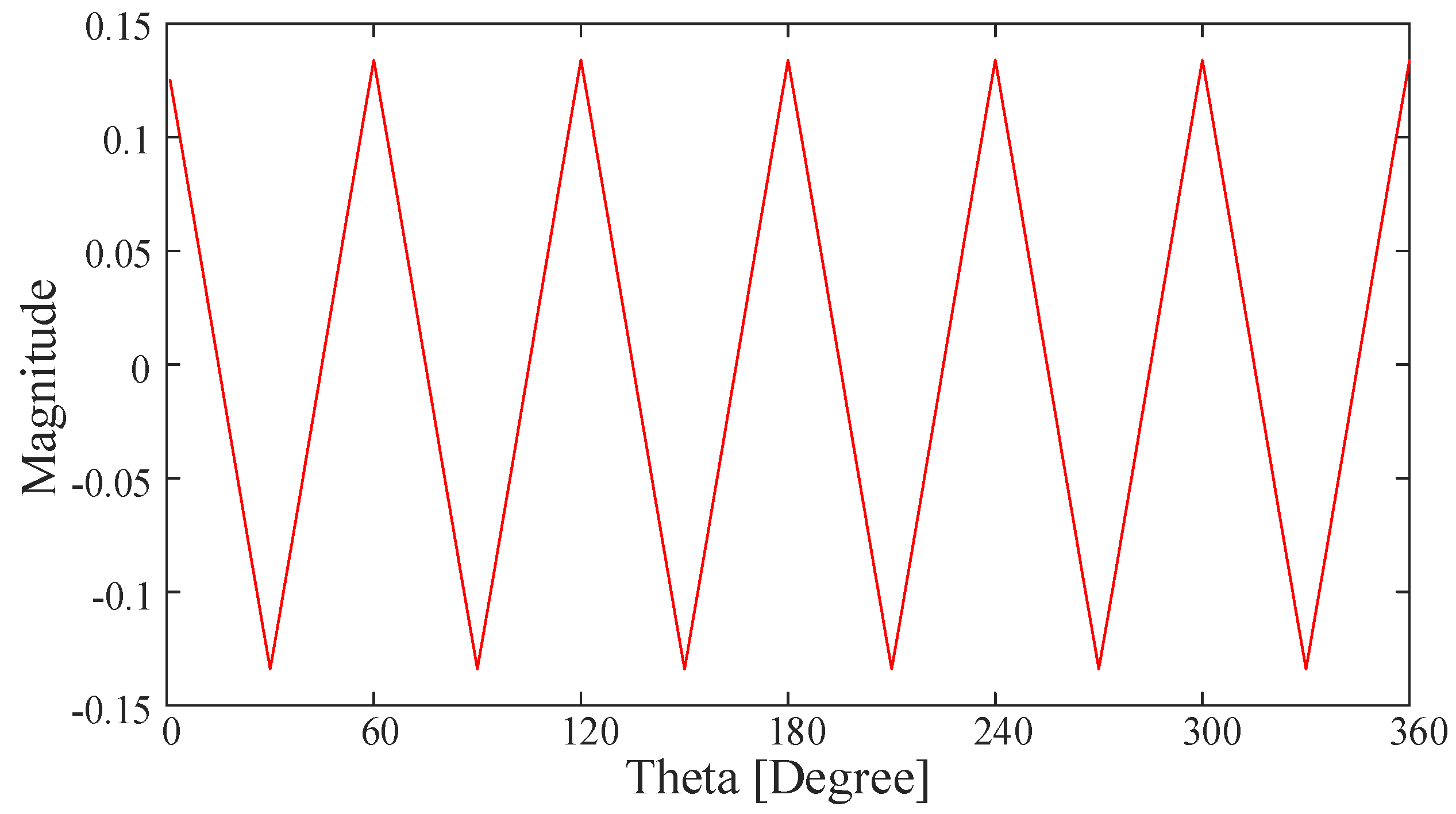
2.3. Relationship between Change Frequency of CMV and Dwell Time in Zero Voltage Vector

When using opposite triangular carrier, the CMV is Vdc/6 in region ②, ④, ⑩, and ⑫ of Figure 2b, –Vdc/6 in region ⑥, and ⑧ of Figure 2b, and 0 in the remaining area. Area ②, and ⑫ of Figure 2b consist of an active voltage vector (100) in ABC winding group and zero voltage vector (111) in XYZ winding group. Region ④, and ⑩ of Figure 2b consist of an active voltage (110) in ABC winding group and XYZ winding group. Region ⑥, and ⑧ of Figure 2b consist of an active voltage (110) in ABC winding group and zero voltage vector (000) on XYZ winding group. If the dwell time of the zero voltage vector in ABC and XYZ winding group is the same, the CMV in region ②, ⑥, ⑧, and ⑫ of Figure 2b can be removed, and the CMV occurs only in region ④, and ⑩. Therefore, the characteristics of the CMV is changed from Figure 2b to Figure 3, and the change frequency of CMV is reduced from 12 to 4 during one switching frequency. This paper proposes a control method that reduce the change frequency of CMV by using synchronization of dwell time in zero voltage vector of ABC and XYZ winding group.

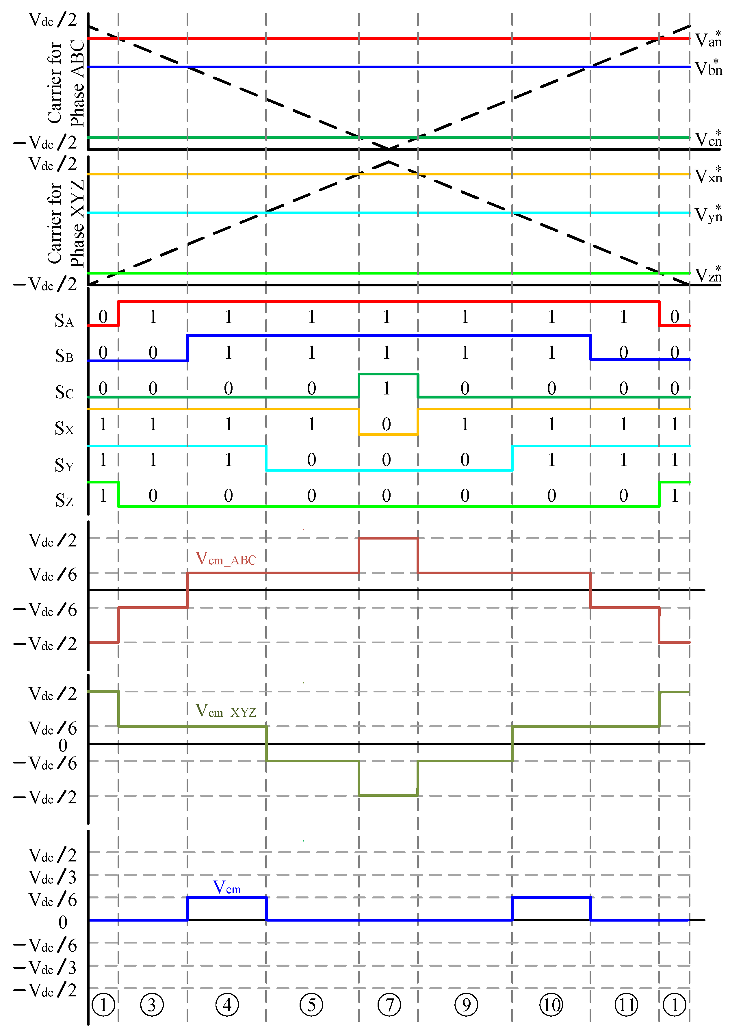
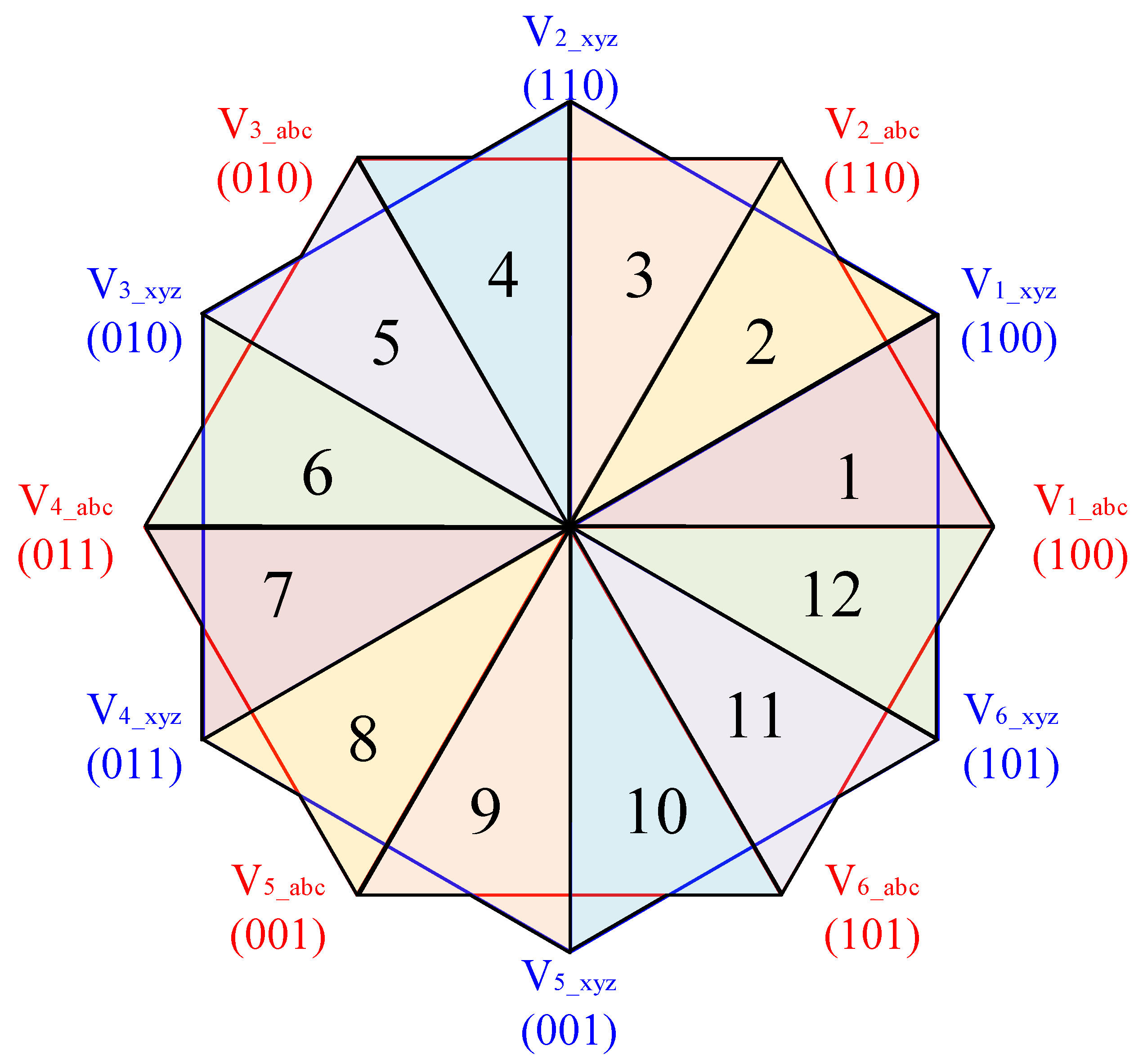
3. Reduction of Change Frequency of CMV by Synchronization of Dwell Time in Zero Voltage Vector

3.1. Analsis of the Dwell Time of Zero Voltage Vector

If the dwell time of the zero voltage vector in ABC and XYZ winding group is the same as shown in region ① and ⑦ of Figure 3, the CMV generated by the difference of the dwell time in zero voltage vector shown in region ②, ⑥, ⑧, and ⑫ of Figure 2b can be removed. The dwell time of the zero voltage vector in ABC and XYZ winding group is obtained from the space vector diagram of the dual three phase motor shown in Figure 4 which has a total of 12 regions classified 30°.
The dwell time of region ① in Figure 2b is determined by the relationship between maximum reference pole voltage in ABC winding group and Vdc/2, and the dwell time of region ⑦ in Figure 2b is determined by the minimum reference pole voltage in ABC winding group and −Vdc/2. The reference of the phase voltage for obtaining the reference of pole voltage on ABC winding group can be defined by Equation (4).
Vas* = Vmcosθ = Vabcs_max*
Vbs* = Vm cos(θ − 120°) = Vabcs_mid*
Vcs* = Vm cos(θ − 240°) = Vabcs_min*
The offset voltage of the ABC winding group in Figure 4 region 1 to apply SVPWM is equal to Equation (5).
Vabc_offset = −(Vabcs_max* + Vabcs_min*)/2 = −(Vas* + Vcs*)/2
The reference pole voltage in ABC winding group is obtained by adding the reference of the phase voltage and the offset voltage given by Equation (6).
Van* = (Vas* − Vcs*)/2 = Vabcn_max*
Vbn* = Vbs* − (Vas* + Vcs*)/2
Vcn* = (Vcs* − Vas*)/2 = Vabcn_min*
The magnitude of the maximum and minimum value of the reference of pole voltage is the same, but the sign is opposite as shown in Equation (6). Thus, the dwell time in zero voltage vector is twice as much as the region ① in Figure 2b. The dwell time in zero voltage vector in Figure 4 region 1 can be obtained using the maximum reference pole voltage in ABC winding group.
The dwell time of the zero voltage vector in dual three phase motor is twice the size of the dwell time of region ① in Figure 2b, which is larger than the maximum reference pole voltage and smaller than Vdc/2. Therefore, the dwell time in zero voltage vector can be obtained as Equation (7).
Vdc/2:(Vdc/2 − Vabcn_max) = TS/2:T0_abc/2
T0_abc = 2*Ts (Vdc/2 − Vabcn_max*)/Vdc
= Ts *   ( V dc     3 V m   cos ( θ     30 ° ) ) / V dc
where Ts, T0_abc, and Vm are the time of one switching frequency, dwell time in zero voltage vector in ABC winding group, and maximum value of the reference phase voltage, respectively.
In Figure 4 region 1, the dwell time of the zero voltage vector in XYZ winding group can be obtained using Equation (8), which is derived from Equations (4)–(7).
T 0 _ xyz   =   Ts *   ( V dc     3 V m   cos θ ) / V dc
The dwell time of the zero voltage vector in ABC and XYZ winding group in Figure 4 region 1 is Equations (7) and (8), which can be generalized as shown in the Equation (9).
T 0   =   Ts *   ( V dc     3 V m α ) / V dc
where α is the same as Table 1.

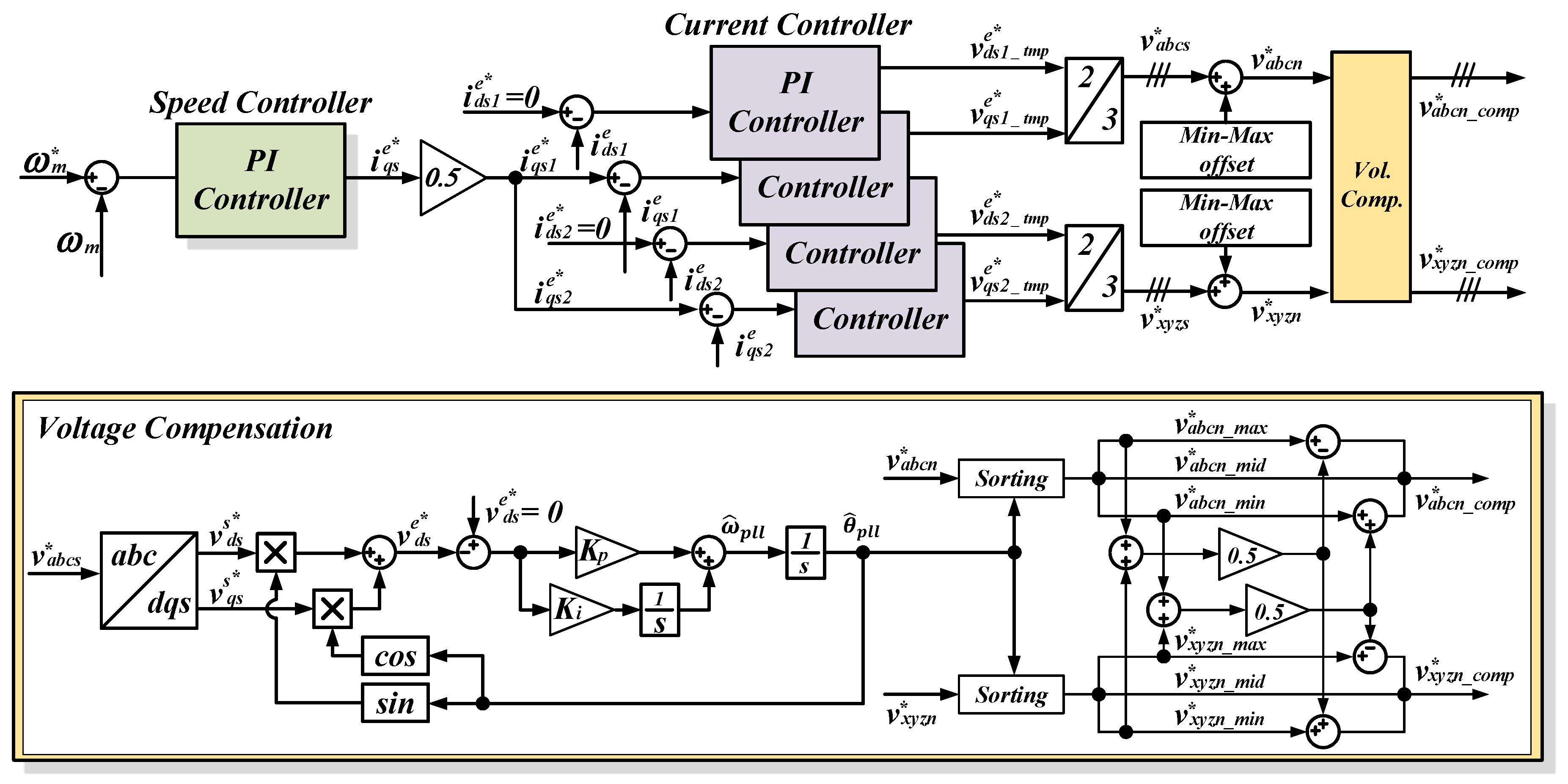
3.2. The Compensation Time in Zero Voltage Vector for CMV Reduction

As shown in Table 1, the dwell time of the zero voltage vector between ABC and XYZ winding group is different, so change frequency occurs 12 times in one switching period as shown in Figure 2b. If the dwell time of the zero voltage vector in ABC and XYZ winding group is the same as Figure 3, the change frequency of CMV can be reduced from 12 to 4 times during one switching frequency. However, the difference of the dwell time in zero voltage vector of ABC and XYZ winding group in Figure 4 region 1 is expressed by
T 0 _ gap 1   =   T 0 _ abc 1     T 0 _ xyz 1   =   Ts *   ( V dc     3 V m   cos ( θ     30 ° ) ) / V dc     Ts * ( V dc     3 V m   cos   ( θ     30 ° ) ) / V dc =   3 T S   V m { ( 1     3 / 2 )   cos θ     sin θ / 2 }
where T0_gap1, T0_abc1, and T0_xyz1 are difference of dwell time in zero voltage vector on ABC and XYZ winding group in Figure 4 region 1, dwell time in zero voltage vector on ABC and XYZ winding group, respectively.
Generalizing the difference of the dwell time in the zero voltage vector is the same as the Equation (11).
T 0 _ gap   =   T 0 _ abc   +   T 0 _ xyz   =   3 T S   V m   T 0 _ err / 2
where the magnitude of T0_err is the same as the one given in Table 2, and it can be expressed by Figure 5.
To reduce the change frequency of CMV, the dwell time of the zero voltage vector in ABC and XYZ winding group has to be identical. The difference of the dwell time in zero voltage vector of the ABC and XYZ winding group is equally distributed to the dwell time in zero voltage vector of ABC and XYZ winding group.
T0_abc_comp = T0_abc − T0_gap/2
T0_xyz_comp = T0_xyz − T0_gap/2
where T0_abc_comp, and T0_xyz_comp are dwell time in zero voltage vector of ABC and XYZ winding group in which the compensation voltage is included in order to reduce the CMV.
In order to reduce the range of CMV of the dual three phase motor, the opposite triangle carrier is used on ABC and XYZ winding group. When the opposite triangle carrier is applied, the change frequency of CMV occurs 8 times due to discordance of the dwell time in zero voltage of ABC and XYZ winding group. Using the analysis and compensation of the dwell time in zero voltage vector of ABC and XYZ winding group, change frequency is removed since it is generated by a mismatch of dwell time of zero voltage vector as shown in Figure 3.

3.3. Overall Configuration of the Proposed Method

The overall proposed control method is illustrated in Figure 6. The speed controller consisting of PI controller is located in the outer loop of the current controller. The speed controller outputs the q-axis reference current (ieqs*) to the input of the current controller in order to control the torque of the dual three phase motor [28]. The q-axis reference current is equally divided into q-axis reference current for ABC (ieqs1*) and XYZ (ieqs2*) winding group. The d-axis reference current (ieds*) that controls the magnetic flux of the ABC (ieds1*) and XYZ (ieds2*) winding group is 0. Each dq-axis current controller adopted a PI controller. The current controllers output the reference of dq-axis voltage. The electric angle for classification calculates angle by using PLL on reference of ABC phase voltage. The classification of the reference pole voltage in ABC and XYZ winding group uses an electric angle. The maximum and minimum values of the reference pole voltage are classified by using the electrical angle. The compensation voltage to reduce the CMV is calculated by using the maximum and minimum reference of pole voltage.

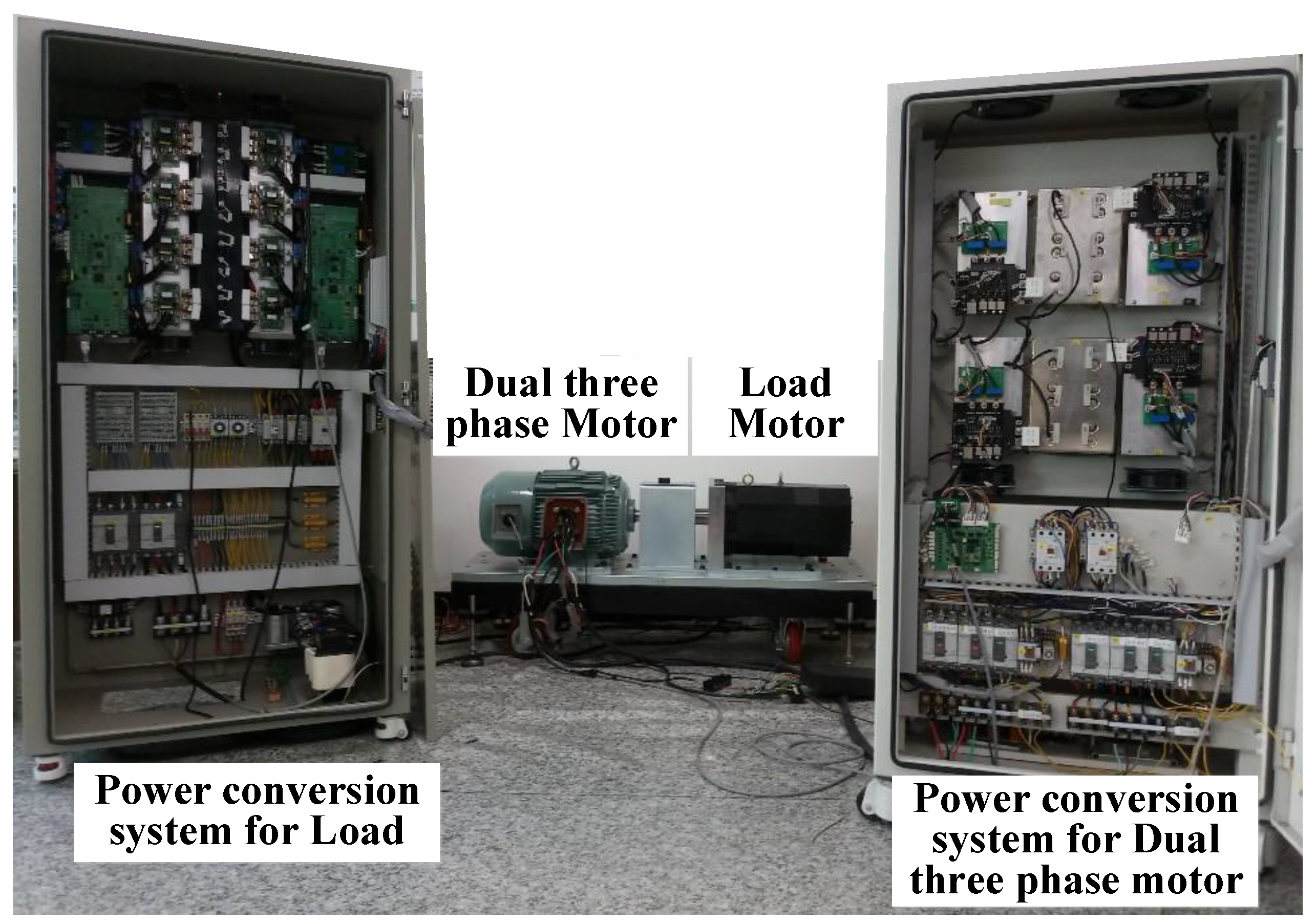
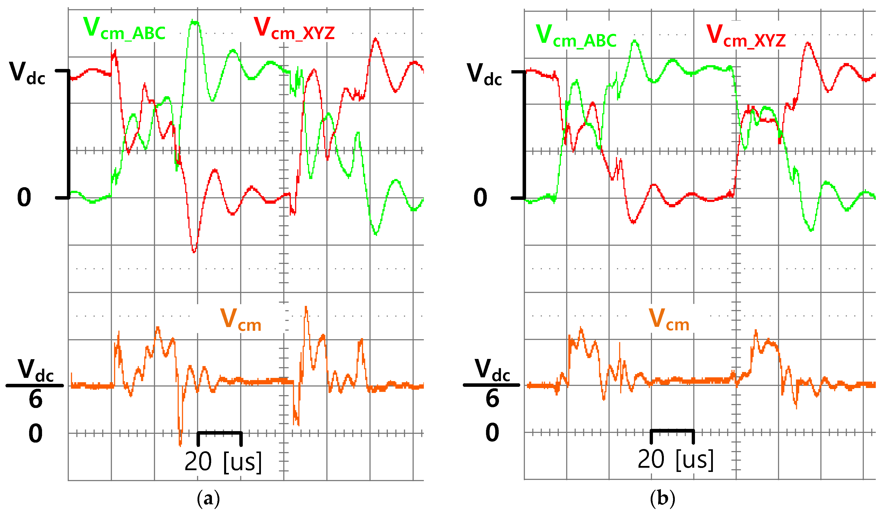
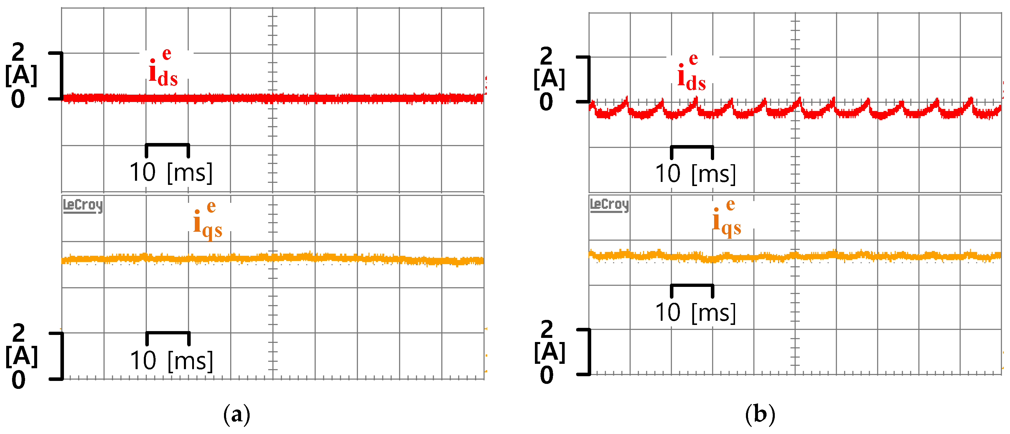
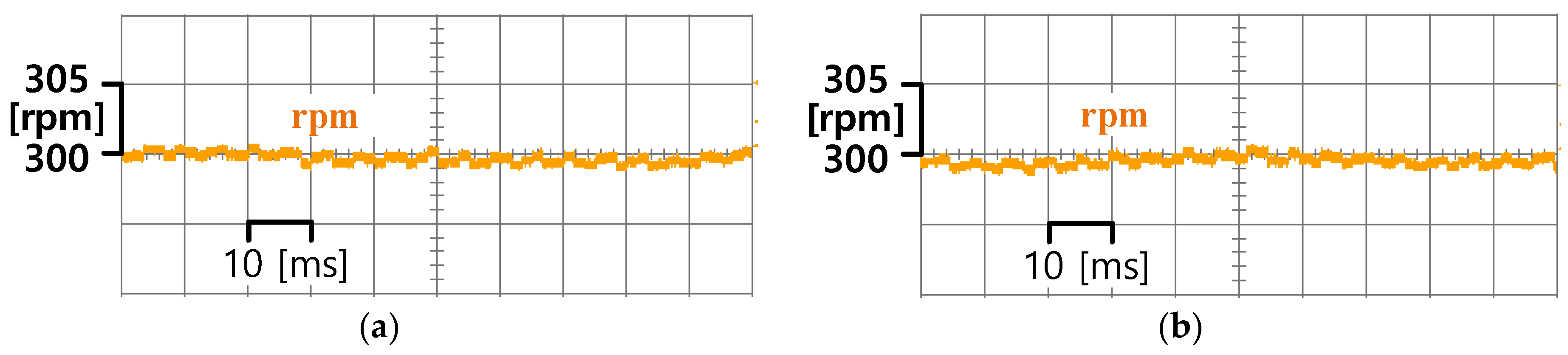
4. Experimental Set-Up and Results

Figure 7 is an MG experimental set used to verify the proposed method, and the main parameters of the dual three phase motor are given in Table 3. The dc link voltage for the PWM inverter is generated by a diode rectifier. The phase voltage is injected to the dual three phase motor by using each inverter module. The control board is based on the DSP TMS320c28346 manufactured by Texas Instruments located in Dallas, Texas, USA. In the three-phase motor for load, the dc link voltage is 700V produced by the PWM converter, the torque control of load motor is carried out using PWM inverter.
Figure 8 shows the CMV before and after applying the CMV reduction algorithm during one switching frequency. Vcm_ABC is the voltage between the ABC neutral point and the bottom of the DC link voltage, Vcm_XYZ is the voltage between the XYZ neutral point and the bottom of DC link voltage, and Vcm is the average of Vcm_ABC and Vcm_XYZ [7]. The range of the CMV in each winding group before applying the CMV reduction algorithm is Vdc as shown in Figure 8a, and remains the same after applying the CMV reduction algorithm as shown in Figure 8b. The change frequency of CMV after applying CMV reduction algorithm is reduced from 12 to 4.
Figure 9 is the dq-axis current waveform before and after applying the CMV reduction algorithm when the dual three phase motor is controlled to 1kW. In Figure 9, ieqs is the sum of ieqs1 and ieqs2, ieds is the sum of ieds1 and ieds2. Before applying the CMV reduction algorithm, ieds is controlled to 0, but after applying the CMV reduction algorithm, ieds has a current ripple of about 1A. The 12th harmonic ripple of ieds after applying proposed method is caused by compensation voltage. The torque component ieqs is controlled to 5.4A, and the control characteristics are similar before and after applying proposed algorithm.
After applying the CMV reduction algorithm, the d-axis current ripple is increased, but the speed of the dual three phase motor is the same before and after applying the algorithm as shown in Figure 10.
The efficiency of the dual three phase motor inverter system before and after applying the CMV reduction algorithm can be calculated through the relationship between inverter input and motor output. The input of the inverter is measured by using the DC side voltage and current with the help of the WT 3000 power analyzer manufactured by Yokogawa as shown in Figure 11. The input power of the inverter before applying the CMV reduction algorithm is 1.09 kW, and input power of the inverter after applying the CMV reduction algorithm is increased to 1.11 kW. The output power of the dual three phase motor is 1kW before and after applying the CMV reduction algorithm. The output power of the dual three phase motor is calculated through the Back-emf constant and speed. The efficiency of the dual three phase motor inverter system before and after applying the CMV reduction algorithm is 91.48% and 90.00%, respectively. The reason for the decrease in efficiency after applying the CMV reduction algorithm is that the distortion of current occurred due to the compensation voltage injected to the reference pole voltage.

5. Conclusions

This paper proposed the CMV reduction algorithm using SVPWM in a dual three phase motor. The opposite triangle carrier was used to reduce the range of the CMV. To reduce the change frequency in CMV, the dwell time of the zero voltage vector in ABC and XYZ winding group was equaled. The change frequency of CMV was decreased by 66% and verified through experiment. The d-axis current ripple was increased, but the characteristics of the q-axis current were similar before and after applying the algorithm. Therefore, the speed characteristic of the dual three phase motor was confirmed to be the same.

Author Contributions

Conceptualization, S.-I.H. and J.-M.K.; methodology, S.-I.H.; software, S.-I.H.; validation, J.-M.K.; data curation, S.-I.H.; writing—original draft preparation, S.-I.H.; writing—review and editing, J.-M.K.; visualization, J.-M.K. All authors have read and agreed to the published version of the manuscript.

Funding

This work was supported by BK21PLUS, Creative Human Resource Education and Research Programs for ICT Convergence in the 4th Industrial Revolution

Institutional Review Board Statement

Not applicable.

Informed Consent Statement

Not applicable.

Data Availability Statement

Accepted and complied with.

Conflicts of Interest

The authors declare no conflict of interest.

References

  1. Barrero, F.; Duran, M.J. Recent Advances in the Design, Modeling, and Control of Multiphase Machines-Part I. IEEE Trans. Ind. Electron. 2016, 63, 449–458. [Google Scholar] [CrossRef]
  2. Bojoi, R.; Cavagnino, A.; Tenconi, A.; Tessarolo, A.; Vaschetto, S. Multiphase Electrical Machines and Drives in the Transportation Electrification. In Proceedings of the 2016 International Conference and Exposition on Electrical and Power Engineering (EPE), Lasi, Romania, 20–22 October 2016. [Google Scholar]
  3. Wang, X.; Wang, Z.; Xu, Z.; He, J.; Zhao, W. Diagnosis and Tolerance of Common Electrical Faults T-Type Three-Level Inverters Fed Dual Three-Phase Drives. IEEE Trans. Power Electron. 2020, 35, 1753–1769. [Google Scholar] [CrossRef]
  4. Hu, Y.; Zhu, Z.; Liu, K. Current Control for Dual Three-Phase Permanent Magnet Synchronous Motors Accounting for Current Unbalance and Harmonics. IEEE J. Emerg. Sel. Top. Power Electron. 2014, 2, 272–284. [Google Scholar]
  5. Karttunen, J.; Kallio, S.; Peltoniemi, P.; Silventoinen, P.; Pyrhonen, O. Decoupled Vector Control Scheme for Dual Three-Phase Permanent Magnet Synchronous Machines. IEEE Trans. Ind. Electron. 2014, 61, 2185–2196. [Google Scholar] [CrossRef]
  6. Zheng, J.; Huang, S.; Rong, F.; Lye, M. Six-Phase Space Vector PWM under Stator One-Phase Open-Circuit Fault Condition. Energies 2018, 11, 1796. [Google Scholar] [CrossRef] [Green Version]
  7. Liu, Z.; Zheng, Z.; Peng, Z.; Li, Y.; Hao, L. A Sawtooth Carrier-Based PWM for Asymmetrical Six-Phase Inverters with Improved Common-Mode Voltage Performance. IEEE Trans. Power Electon. 2018, 33, 9444–9458. [Google Scholar] [CrossRef]
  8. Shen, Z.; Jiang, D.; Liu, Z.; Ye, D.; Li, J. Common-Mode Voltage Elimination for Dual Two-Level Inverter-Fed Asymmetrical Six-Phase PMSM. IEEE Trans. Power Electron. 2020, 35, 3828–3840. [Google Scholar] [CrossRef]
  9. Gopakumar, K.; Ranganthan, V.T.; Bhat, S.R. Split-phase Induction Motor Operation from PWM Voltage Source Inverter. IEEE Trans. Ind. Appl. 1993, 29, 927–932. [Google Scholar] [CrossRef]
  10. Ahmet, M.H.; Un, E. A High-Performance PWM Algorithm for Common-Mode Voltage Reduction in Three-Phase Voltage Source Inverters. IEEE Trans. Power Electron. 2011, 26, 1998–2008. [Google Scholar]
  11. Lee, S.; Jung, J.; Hwang, S.; Kim, J.; Cho, H. Common-mode Voltage Reduction Method for H7 Inverter Using DPWM Offset Based Modulation Technique. In Proceedings of the 2018 IEEE Energy Conversion Congress and Exposition (ECCE), Portland, OR, USA, 23–27 September 2018. [Google Scholar]
  12. Jung, J.; Park, J.; Kim, J.; Son, Y. DC-Link Voltage Balance Control Using Fourth-Phase for 3-Phase 3-Level NPC PWM Converters with Common-Mode Voltage Reduction Technique. J. Power Electron. 2019, 19, 108–118. [Google Scholar]
  13. Son, Y.; Sul, S. Generalization of Active Filters for EMI Reduction and Harmonics Compensation. IEEE Trans. Ind. Appl. 2006, 42, 545–551. [Google Scholar] [CrossRef]
  14. Akagi, H.; Hasegawa, H.; Doumoto, T. Design and Performance of a Passive EMI Filter for Use with a Voltage-source PWM Inverter. IEEE Trans. Power Electron. 2004, 19, 1069–1076. [Google Scholar] [CrossRef]
  15. Cacciato, M.; Consoli, A.; Scarcella, G.; Testa, A. Reduction of Common-Mode Currents in PWM Inverter Motor Drives. IEEE Trans. Ind. Appl. 1999, 35, 545–551. [Google Scholar] [CrossRef]
  16. Un, E.; Ahmet, M.H. A Near-State PWM Method with Reduced Switching Losses and Reduced Common-Mode Voltage for Three-Phase Voltage Source Inverters. IEEE Trans. Ind. Appl. 2009, 45, 782–793. [Google Scholar] [CrossRef]
  17. Oriti, G.; Julian, A.L.; Lipo, T.A. A new space vector modulation strategy for common mode voltage reduction. In Proceedings of the PESC97. Record 28th Annual IEEE Power Electronics Specialists Conference. Formerly Power Conditioning Specialists Conference 1970-71, Power Processing and Electronic Specialists Conference 1972, Saint Louis, MO, USA, 27 June 1997. [Google Scholar]
  18. Huang, J.; Shi, H. Reducing the Common-Mode Voltage through Carrier Peak Position Modulation in an SPWM Three-Phase Inverter. IEEE Trans. Power Electron. 2014, 29, 4490–4495. [Google Scholar] [CrossRef]
  19. Nguyen, T.T.; Nguyen, N. An Efficient Four-state Zero Common-Mode Voltage PWM Scheme with Reduced Current Distortion for a Three-Level Inverter. IEEE Trans. Ind. Electron. 2018, 65, 1021–1030. [Google Scholar] [CrossRef]
  20. Le, Q.A.; Lee, D.-C. Elimination of Common-Mode Voltages Based on Modified SVPWM in Five-Level ANPC Inverters. IEEE Trans. Power Electron. 2019, 34, 173–183. [Google Scholar] [CrossRef]
  21. Seo, I.; Belaynehn, N.B.; Park, C.; Kim, J. A Study of Common Mode Voltage Generation According to Modulation Methods and Reduction Strategies on MMC System. In Proceedings of the 2018 IEEE Energy Conversion Congress and Exposition (ECCE), Portland, OR, USA, 23–27 September 2018. [Google Scholar]
  22. Xiong, W.; Sun, Y.; Su, M.; Zhang, J.; Liu, Y.; Yang, J. Carrier-Based Modulation Strategies with Reduced Common-Mode Voltage for Five-Phase Voltage Source Inverters. IEEE Trans. Power Electron. 2018, 33, 2381–2394. [Google Scholar] [CrossRef]
  23. Payami, S.; Behera, R.K.; Iqbal, A.; Al-Ammari, R. Common-Mode Voltage and Vibration Mitigation of a Five-Phase Three-Level NPC Inverter-Fed Induction Motor Drive System. IEEE J. Emerg. Sel. Top. Power Electron. 2015, 3, 349–361. [Google Scholar] [CrossRef]
  24. Kim, D.; Ma, J.; Kim, J. Phase to Phase Interleaved Method to Reduce the Common Mode Voltage for Seven Phase BLDCM Drive. In Proceedings of the 2019 10th International Conference on Power Electronics and ECCE Asia (ICPE 2019-ECCE Asia), Busan, Korea, 27–30 May 2019. [Google Scholar]
  25. Liu, Z.; Wang, P.; Sun, W.; Shen, Z.; Jiang, D. Sawtooth Carrier-Based PWM Methods with Common-Mode Voltage Reduction for Symmetrical Multiphase Two-Level Inverters with Odd Phase Number. IEEE Trans. Power Electron. 2021, 36, 1171–1183. [Google Scholar] [CrossRef]
  26. Zhang, Z.; Jin, S.; Zhang, Z.; Zhang, F.; Li, B. Novel space vector PWM technology with lower common-mode voltage for dual three-phase PMSM. IET Power Electron. 2020, 7, 1426–1433. [Google Scholar] [CrossRef]
  27. Van der Broeck, H.W.; Skudelny, H.C. Analysis and realization of a pulse width modulator based on voltage space vectors. IEEE Trans. Ind. Appl. 1988, 24, 142–150. [Google Scholar] [CrossRef]
  28. Feng, G.; Lai, C.; Kelly, M.; Narayan, C.K. Dual Three-Phase PMSM Torque Modeling and Maximum Torque per Peak Current Control Through Optimized Harmonic Current Injection. IEEE Trans. Ind. Electron. 2019, 66, 3356–3368. [Google Scholar] [CrossRef]
Figure 1. Topology of the dual three phase two level inverter system.
Energies 14 00282 g001
Figure 2. Common-mode voltage (CMV) in dual three phase motor according to carrier applied SVPWM. (a) Same triangle carrier; (b) Opposite triangle carrier.
Energies 14 00282 g002
Figure 3. The switching method to reduce the change frequency of CMV.
Energies 14 00282 g003
Figure 4. The space vector diagram of dual three phase motor with division of region.
Energies 14 00282 g004
Figure 5. T0_err according to electric angle.
Energies 14 00282 g005
Figure 6. Proposed total control block diagram.
Energies 14 00282 g006
Figure 7. Experimental configuration for dual three phase motor.
Energies 14 00282 g007
Figure 8. Experimental results of CMV. (a) Before applying proposed algorithm; (b) After applying proposed algorithm.
Energies 14 00282 g008
Figure 9. Experimental results of dq-axis current. (a) Before applying proposed algorithm; (b) After applying proposed algorithm.
Energies 14 00282 g009
Figure 10. Experimental results of speed. (a) Before applying proposed algorithm; (b) After applying proposed algorithm.
Energies 14 00282 g010
Figure 11. Experimental results of input power in inverter system. (a) Before applying proposed algorithm; (b) After applying proposed algorithm.
Energies 14 00282 g011
Table 1. α according to the region.
RegionABC Winding GroupXYZ Winding Group
1cos(θ − 30°)cosθ
2cos(θ − 60°)
3cos(θ − 90°)
4cos(θ − 120°)
5cos(θ − 150°)
6cos(θ − 180°)
7cos(θ − 210°)
8cos(θ − 240°)
9cos(θ − 270°)
10cos(θ − 300°)
11cos(θ − 330°)
12cosθ
Table 2. T0_err according to the region.
RegionT0_errRegionT0_err
1(1 − 3 /2)cosθ − sinθ/27(−1 + 3 /2)cosθ + sinθ/2
2(1 − 3 /2)(cosθ − sinθ)8(1/2 + 3 /2)(cosθ − sinθ)
3cosθ/2 − (1 − 3 /2)sinθ9−cosθ/2 + (1 − 3 /2)sinθ
4−cosθ/2 − (1 − 3 /2)sinθ10cosθ/2 + (1 − 3 /2)sinθ
5(−1/2 − 3 /2)(cosθ − sinθ)11(1/2 − 3 /2)(cosθ + sinθ)
6(1 + 3 /2)cosθ − sinθ/212(1 − 3 /2)cosθ + sinθ/2
Table 3. Main parameters in dual three phase motor.
Rated speed300 rpmStator resistance0.434 Ω
Switching frequency6 kHzStator inductance0.0141 mH
DC link voltage540 VdcBack-emf constant0.393 V/rpm
Publisher’s Note: MDPI stays neutral with regard to jurisdictional claims in published maps and institutional affiliations.

