1. Introduction
A high level of solar radiation is experienced throughout most of Thailand throughout the year. The average daily value of solar radiation is around 18.2 MJ/m
2-day with the highest levels of solar radiation experienced in the months of April and May, between 20 and 24 MJ/m
2-day [
1,
2,
3]. These conditions cause significant thermal accumulation in buildings. Therefore, energy consumption in buildings is due mainly to the air conditioning system and lighting, which has been increasing due to the energy demands of modern society to improve the comfort of the occupants. Approximately 30% of total energy consumption in residential and commercial buildings is demand for artificial lighting. Nowadays, buildings are designed and constructed to provide their occupants with a better-quality environment and to improve energy conservation with optimal designs and functional practices [
4,
5].
Daylight is one solution to save energy consumption in buildings because it is free and a valuable light source for internal building areas throughout the day [
6,
7,
8]. Effective daylight utilization can result in energy savings. The use of natural daylight in buildings also significantly improves the visual and physical comfort of the building. Individuals spend most of their time inside [
9,
10,
11,
12,
13]. Windows permit daylight to illuminate interior building spaces, but parts of the deeper internal building areas do not obtain daylight, and heat transfers through windows as well [
14]. Effects of insufficient daylight within deeper building areas and thermal accumulation in buildings due to daylight illumination mean that the artificial lighting system can be an option for illumination and contributes to reducing approximately 30% of total building energy consumption [
15].
Reducing the artificial lighting energy consumption during the daytime is an issue for energy savings [
13,
16,
17]. The design of architectural structures that can carry adequate daylight into the internal building areas results in energy conservation for both illumination and the air conditioning system [
14,
15,
18,
19,
20,
21,
22,
23]. Light pipes are an alternative way to provide daylight into indoor spaces of buildings, which is useful for spaces with or without glazing opening [
24,
25]. Light pipe systems may be straight or have bends. Commercial light pipes can be defined as a hollow tube to allow the illumination into deeper parts of buildings that do not receive sufficient daylight. Light pipes can be responsible for reducing the electricity consumption of artificial lighting systems [
5].
Many studies have investigated various components of light pipe systems to improve the performance, such as integrating other functions such as ventilation. The integration of a light pipe system into a natural stack ventilation and solar heating was investigated by Shao and Riffat [
26]. A horizontal light pipe with a trapezoidal shape was designed by Canziani et al. who used an active reflector to track the solar rays and further improved illumination into deeper areas by increasing the uniformity [
27]. Light tubes with apertures attached have also been used to transmit daylight [
28]. Uniform lighting levels on different levels of buildings can be provided by vertical light pipes, lighting multiple areas [
29]. An illuminance proportion of 14% under cloudy sky and 7% for sunny conditions in winter and cloudy conditions was investigated using the light pipes [
30]. Mohelnikova evaluated the efficiency of light pipes to be between 0.2 and 0.5, when different diameters of light pipes were studied [
31]. Apart from these, the term “daylight penetration factor” (DPF) of light pipes was used to determine the performance of a daylight system, which describes the relation of the internal illuminance due to a light pipe against the total external illuminance [
32,
33,
34]. A good lighting system requires 1–2% daylight factor (DF) for activity in residence and 2–4% DF for activities in office buildings under International Commission on Illumination (CIE) standard for overcast conditions [
35]. The relationship of the average inside illuminance and different diameters of light pipes was investigated by Vasilakopoulou et al. [
36]. The performance of light pipes was experimentally investigated under subtropical climates in Instanbul [
25], Hong-Kong [
37], Korea [
38], Beijing [
39], and Jordan [
40] which demonstrated that good results and a uniform light distribution can be provided to buildings using light pipes.
In Thailand, aluminum and zinc alloy sheet metal were generally used as roofing and siding material of buildings because of its lightweight, superior corrosion resistance and higher chemical durability than steel sheets [
41,
42,
43]. Our previous presented work [
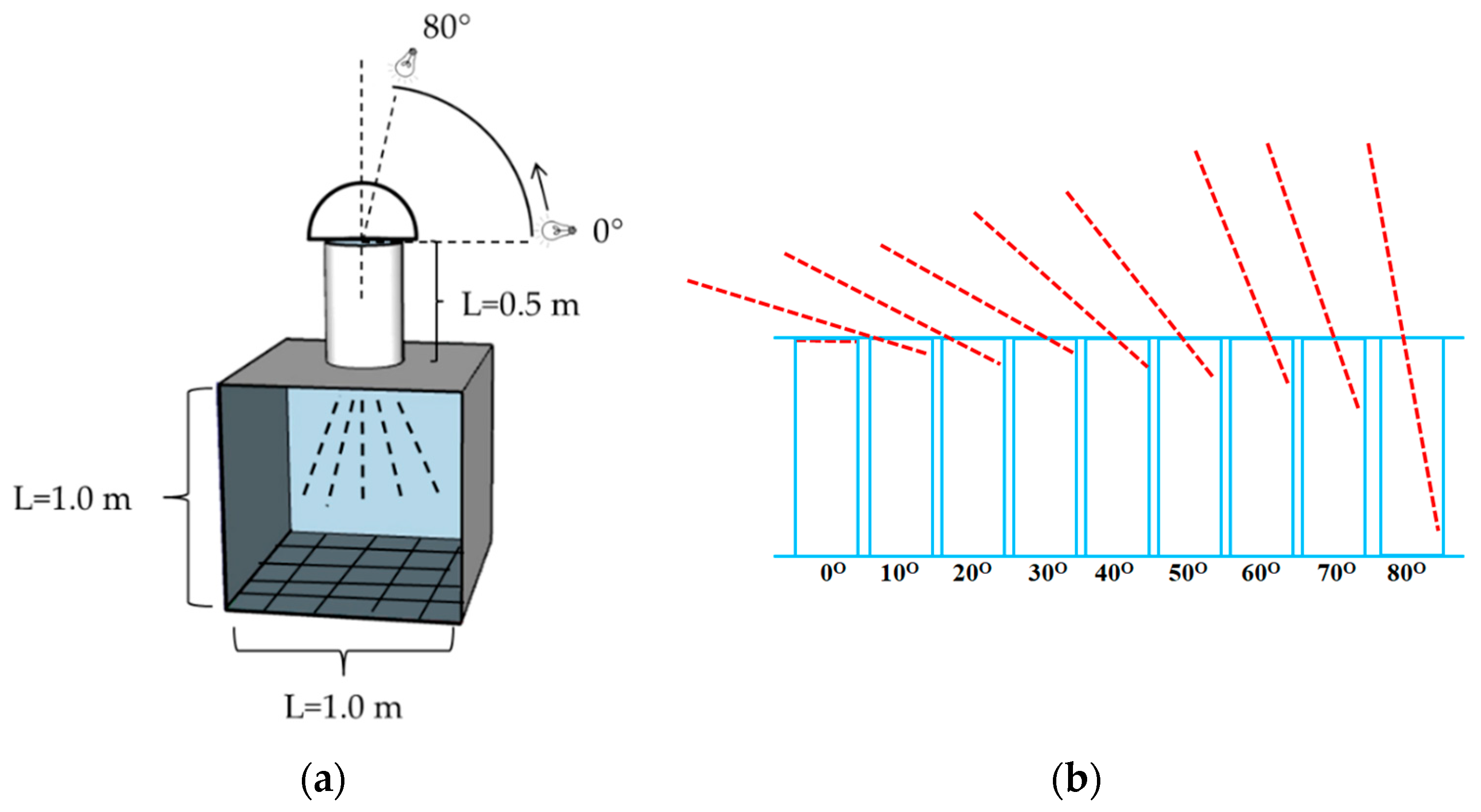
44] designed and constructed the light tubes with a fixed length of 0.5 m and the different diameters of 0.20, 0.25, and 0.30 m, which were made from commercial aluminum and zinc alloy sheets. That work demonstrated only the reflection performance of hollow light tubes at each condition. To appropriately consider and utilize the illumination of the vertical light hollow tubes for transmitting light into buildings, this current investigation was focused on examining the improved illumination distribution at the top and bottom ends, light transmission performance, the internal illuminance distribution on the floor plane, and the daylight factor at various incident angles of the light source. Furthermore, the correlation to these obtained experimental values of the vertical light hollow tubes in each material type at different diameters and incident elevation angle was also investigated and compared.
3. Results and Discussion
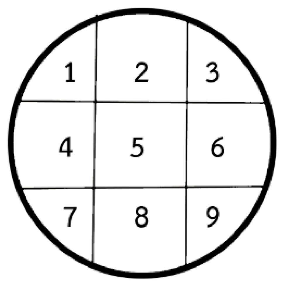
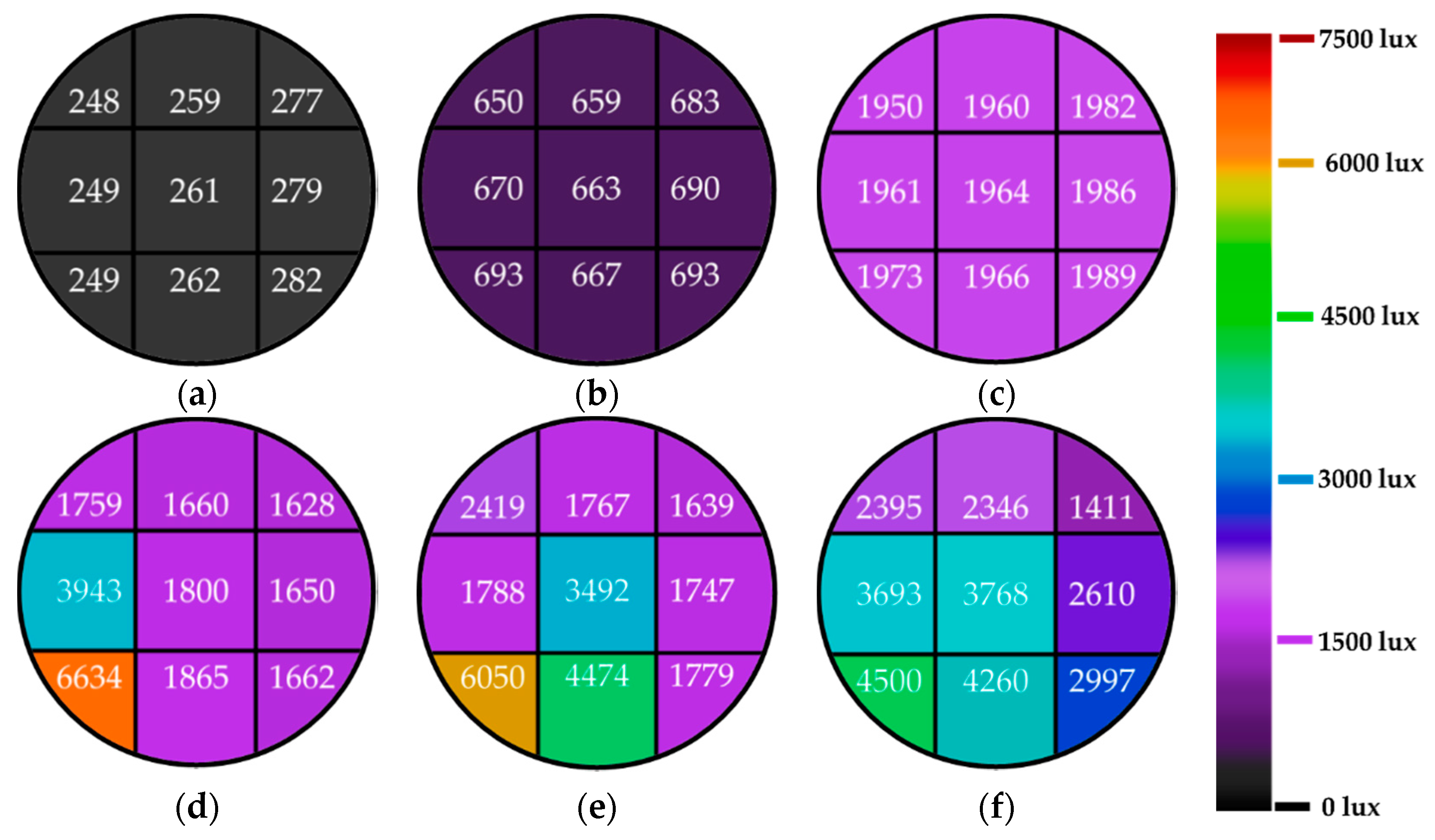
Figure 4 presents the internal illumination contours of the top positions of the aluminum alloy light tube, with a diameter of 0.25 m, at various incident light angles. A color map on the two-dimensional horizontal plane demonstrates the illuminance distribution at the top position of the hollow light pipe. The illumination of the top position was between 248 lux and 282 lux at the incident light angle of 0°, which was uniformly distributed. While increasing the incident light angle from 0° to 30°, the illuminance distribution at the top position was nearly uniform in value. When the incident light angle increased from 30° to 80°, the internal illuminance distribution became nonuniform in some positions, as exhibited in
Figure 4d–f. As the incident light angle increased from 0° to 80°, the internal illumination distribution at the top end changed in each condition. The illuminance value at each position on the top increased in value when the incident angle increased, as displayed in
Figure 4.
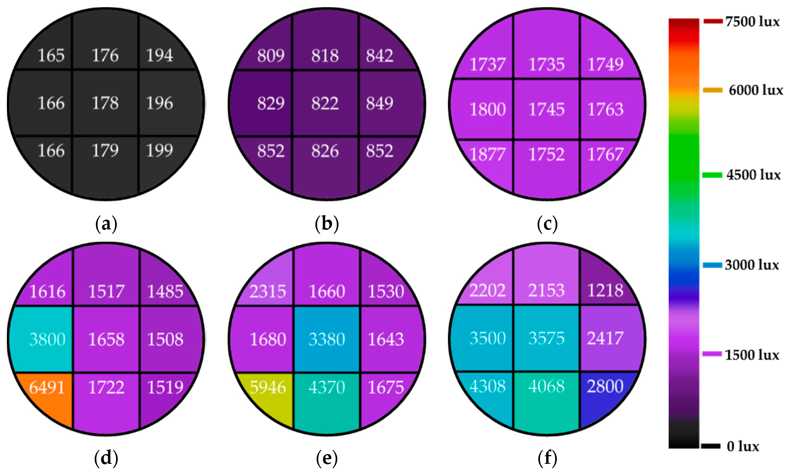
Figure 5 illustrates illumination distribution of the top end of the zinc alloy hollow light pipe with a diameter of 0.25 m with various angles of incidents. At the incident angle of 0°, the illumination of the end was between 165 lux and 199 lux, which uniformly illuminated the area, as shown in the color map. Increasing the incident angle from 0° to 30° led to nearly uniform illuminance for all angles. When the incident light angle increased from 30° to 80°, the illumination became nonuniformly distributed, as exhibited in
Figure 5d–f. When increasing the incident angle from 0° to 80°, the illumination distinctly increased.
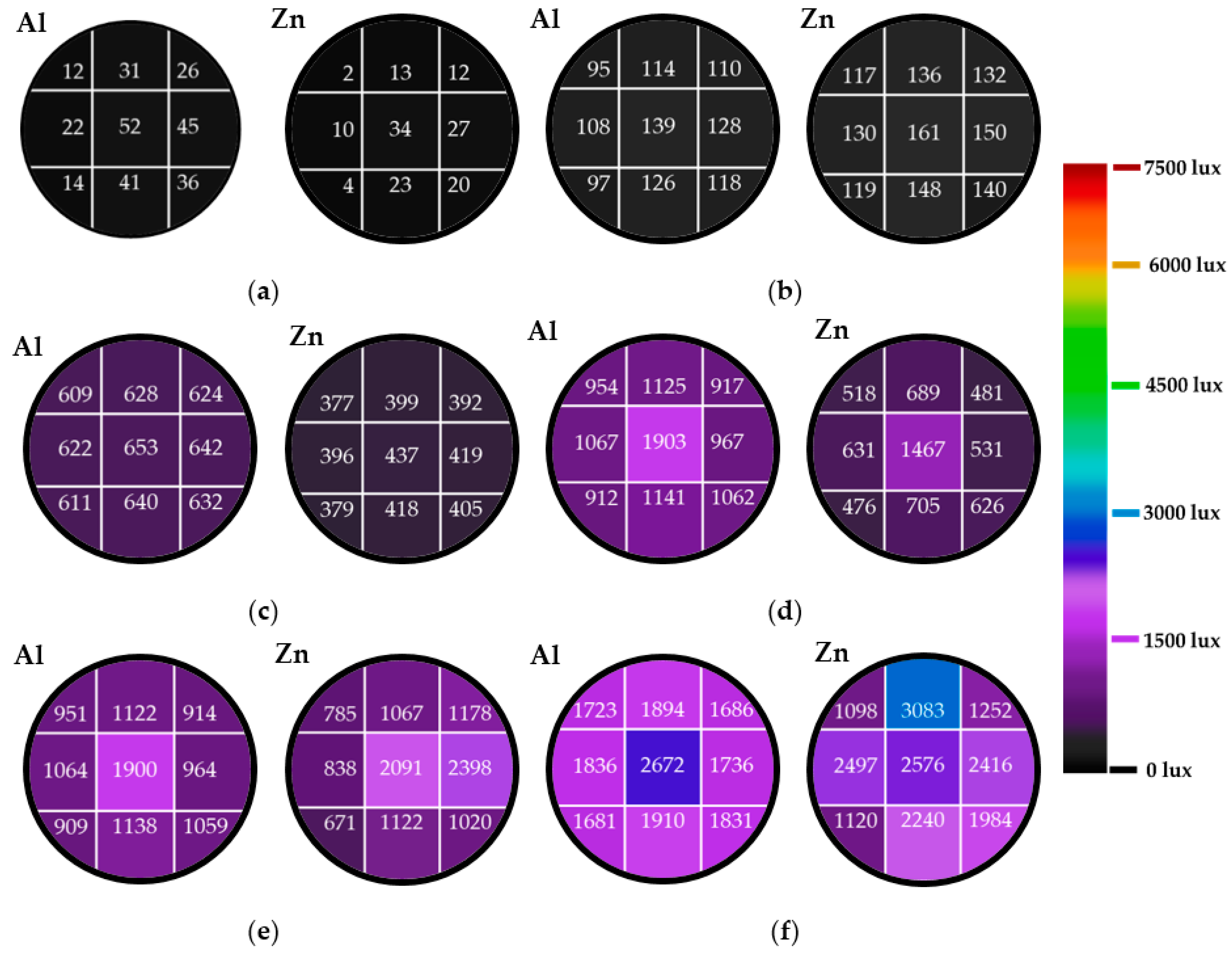
Figure 6 demonstrates the illumination levels on the bottom of both aluminum alloy and zinc alloy hollow light pipes, with the same diameter of 0.25 m and tube length of 0.5 m at different incident angles. When using the aluminum alloy hollow light pipe, the illumination was between 12 lux and 52 lux at the incident light angle of 0°, which was uniformly distributed. The zinc alloy tube had illumination values between 2 lux and 34 lux with a nonuniform illuminance distribution at the incident angle of 0°. When the incident angle was increased from 0° to 30°, the illuminance distribution at the bottom of both types was nearly uniform. When the incident light angle increased from 30° to 80°, the illuminance distribution became nonuniformly distributed, as exhibited in
Figure 6d–f. The illumination distribution for both aluminum alloy and zinc alloy tubes at the bottom varied when the incident light angle was changed from 0° to 80°. The illuminance at the bottom increased with the increase of the incident angle from 0° to 80°, as illustrated in
Figure 6.
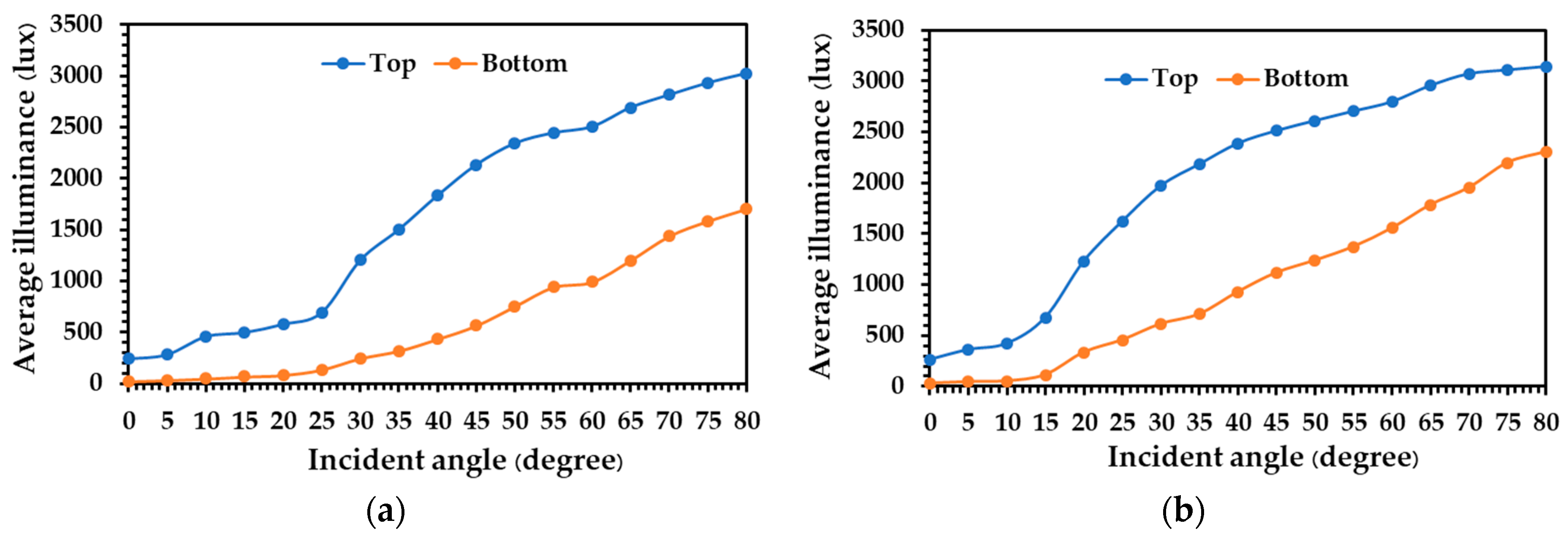
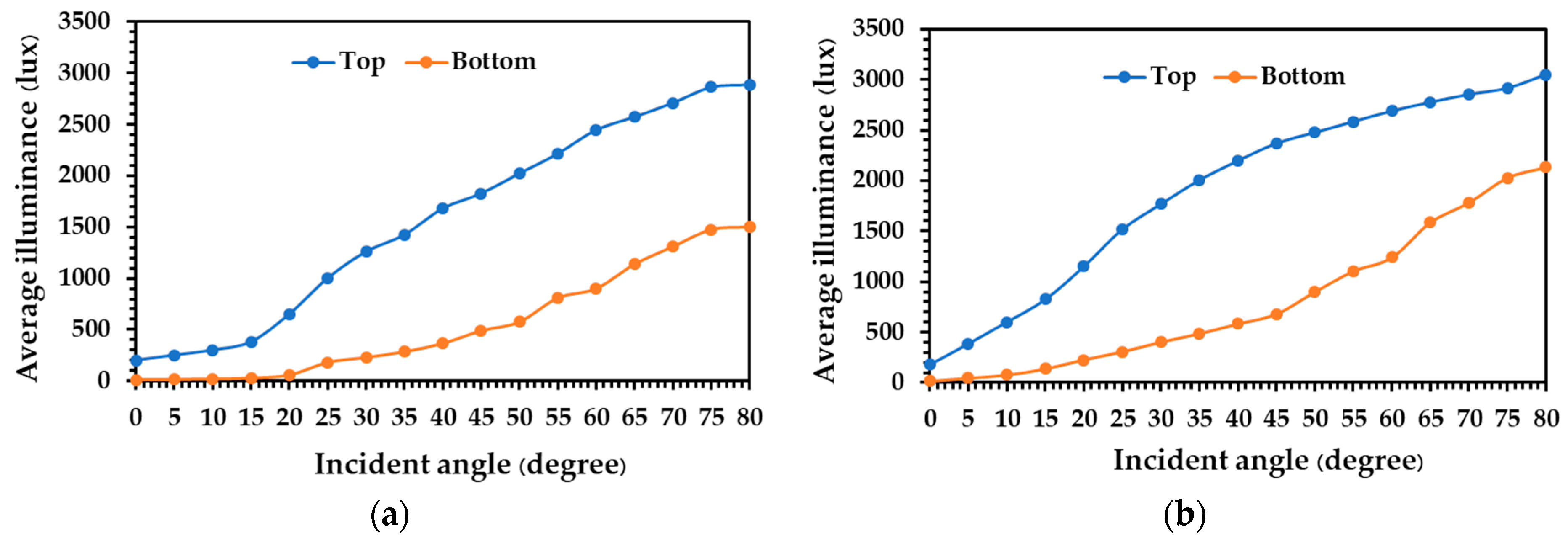
The nine measurements of illumination at the top and bottom were used to calculate the average illuminance for both aluminum alloy and zinc alloy hollow light pipes with a length of 0.5 m and different diameters of 0.20 m, 0.25 m, and 0.30 m. When using the aluminum alloy hollow light pipe with diameters of 0.20 m, 0.25 m, and 0.30 m, the average illuminance at different incident angles is shown in
Figure 7. When the incident angle was varied, a change of luminous intensity at the top and bottom of the tube was achieved. At the top position of the tube with the diameter of 0.20 m, the average luminous intensity increased from 243 lux to 3022 lux; at the bottom end of the tube with a diameter of 0.20 m, the average luminous intensity increased from 22 lux to 1702 lux, when the incident light angle to the tube increased from 0° and 80°, as displayed in
Figure 7a. For the diameters of 0.25 m and 0.30 m, the trend of the average illuminance at the top and bottom positions was similar to that of the tube with a 0.20 m diameter, as exhibited in
Figure 7b,c. For the tube with a diameter of 0.25 m, the average luminous intensity increased from 261 lux to 3142 lux at the top end and from 31 lux to 2304 lux at the bottom end position of the tube with an increase in the incident light angle to the light tube between 0° and 80°, as illustrated in
Figure 7b. For the diameter of 0.30 m, the average luminous intensity increased from 220 lux to 3549 lux at the top end and from 40 lux to 2591 lux at the bottom end when there was an increase of the incident angle to the light tube from 0° to 80°, as illustrated in
Figure 7c.
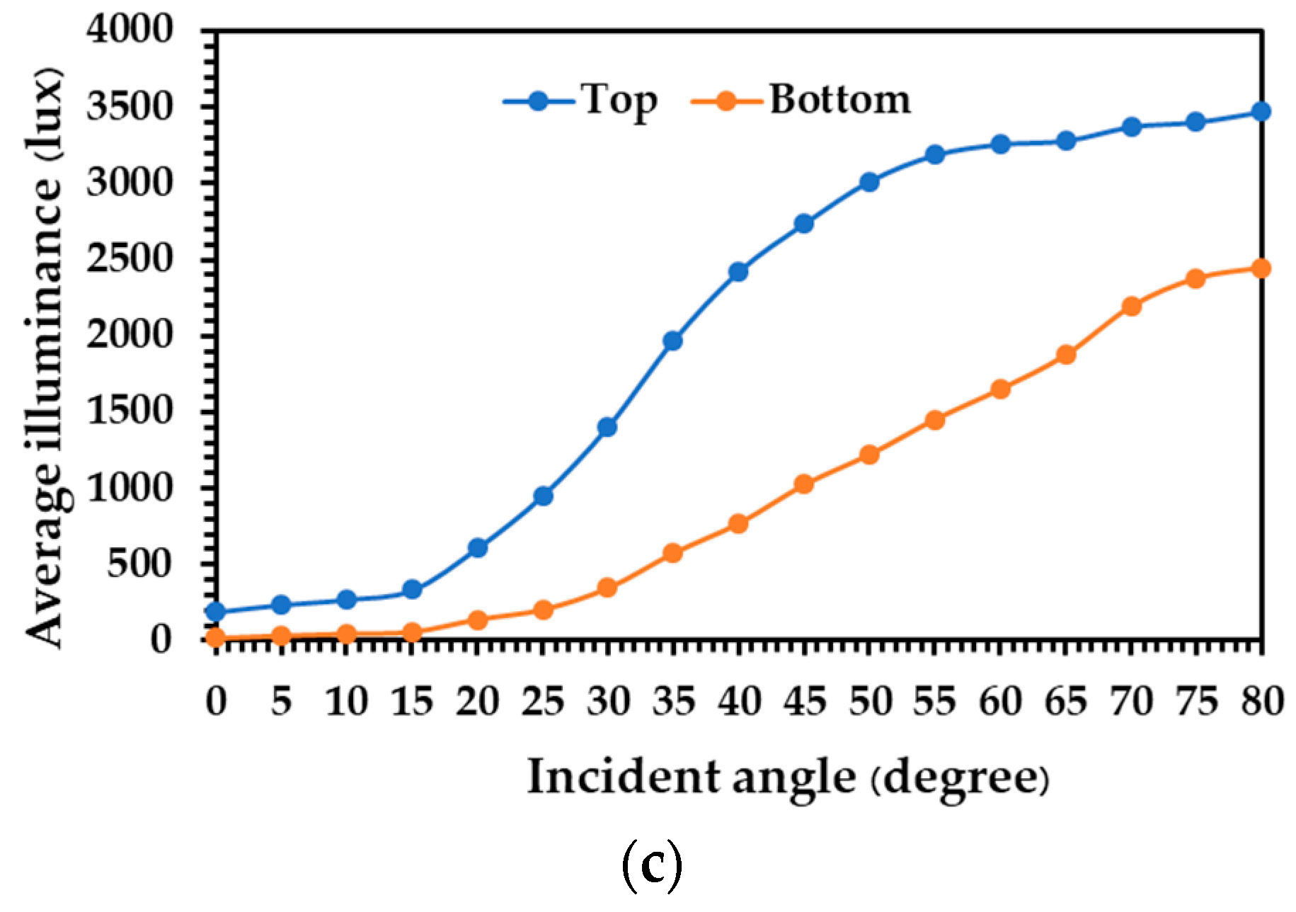
The illuminance of zinc alloy tubes with different diameters of 0.20 m, 0.25 m, and 0.30 m, and height of 0.5 m, at various incident angles are shown in
Figure 8. A variation in the incident light angle to the tube led to the changes in luminous intensity at the top and bottom of the zinc alloy tube. The trend of the illuminance of zinc alloy tubes with the diameters of 0.20 m, 0.25 m, and 0.30 m the at the top and bottom was similar to that of the aluminum alloy tube, as illustrated in
Figure 8. At the top end of zinc alloy light tubes, the illuminance intensity increased from 200 lux to 2889 lux for 0.20 m, from 180 lux to 3052 lux for 0.25 m, and from 190 lux to 3469 lux for the 0.30 m diameter pipes, respectively, with an increase in the incident light angle to the light tube between 0° and 80°. At the bottom of the zinc alloy light tubes, the illuminance intensity increased from 12 lux to 1502 lux for 0.20 m, from 16 lux to 2133 lux for 0.25 m, and from 17 lux to 2448 lux for 0.30 m, respectively, when there was an increase of the incident light angle to the light tube from 0° to 80°. It was observed that the luminous intensity increased at the top and bottom of both aluminum alloy and zinc alloy vertical light tube with an increase of the incident angle to the light source. When considering the low incident angles into the light tube, a major part of the light beam was reflected and little was directly transmitted through the vertical tube, which could lead to the lower illuminance intensity at the top and bottom end positions at the low incident angles of the light source. While the higher incident angles of light source into the light tube was examined, an increase of the illuminance intensity at the top and bottom of the light tubes was achieved, which was a result of more direct light penetration and less incidental light reflection.
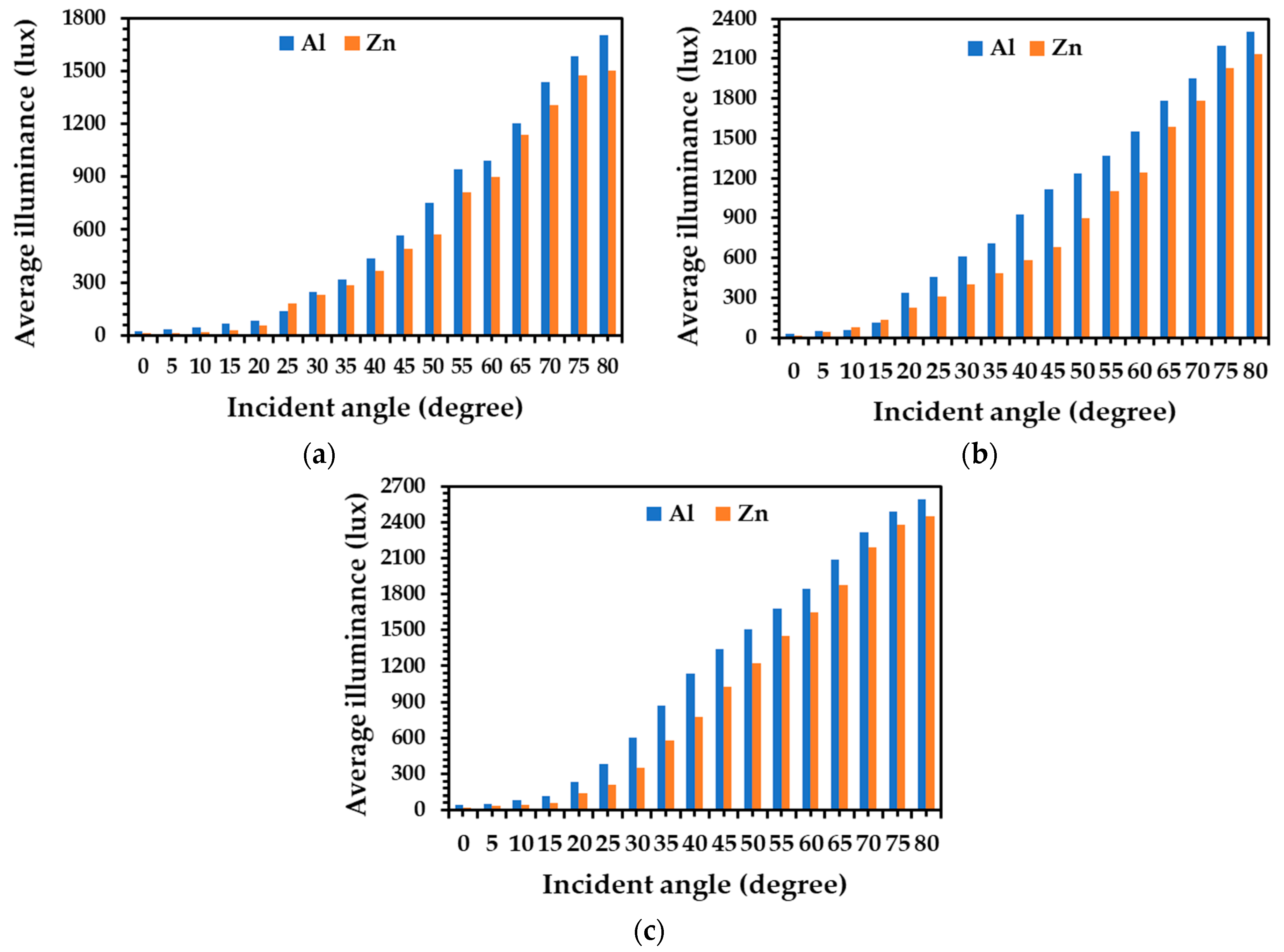
When considering the different types of tube materials, it was observed that the average luminous intensity at the bottom end of the aluminum alloy tubes having a diameter 0.20 m was higher than that of the zinc alloy tube for each incident light angle, as demonstrated in
Figure 9a. For the diameters of 0.25 m and 0.30 m, the average illuminance of the aluminum alloy tube and zinc alloy tube was similar to that of the light tube with a diameter of 0.20 m, as shown in
Figure 9b,c. This indicates that the internal surface of the aluminum alloy tube light showed better reflection, leading to an improvement in the light transmission performance within the tube.
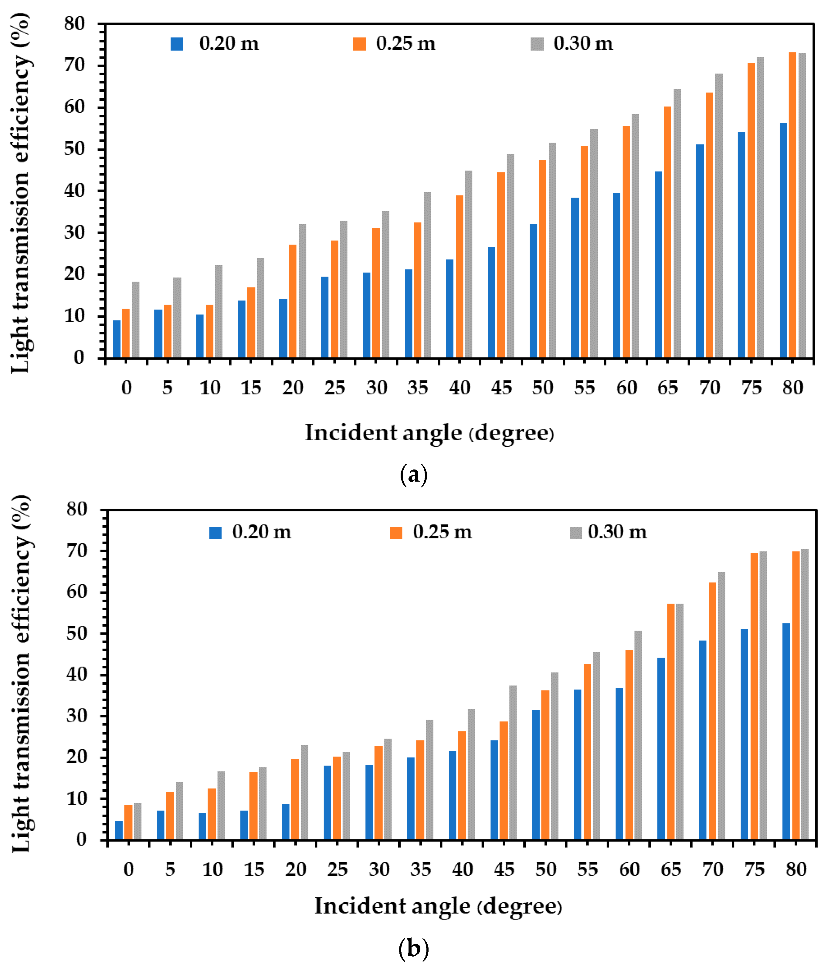
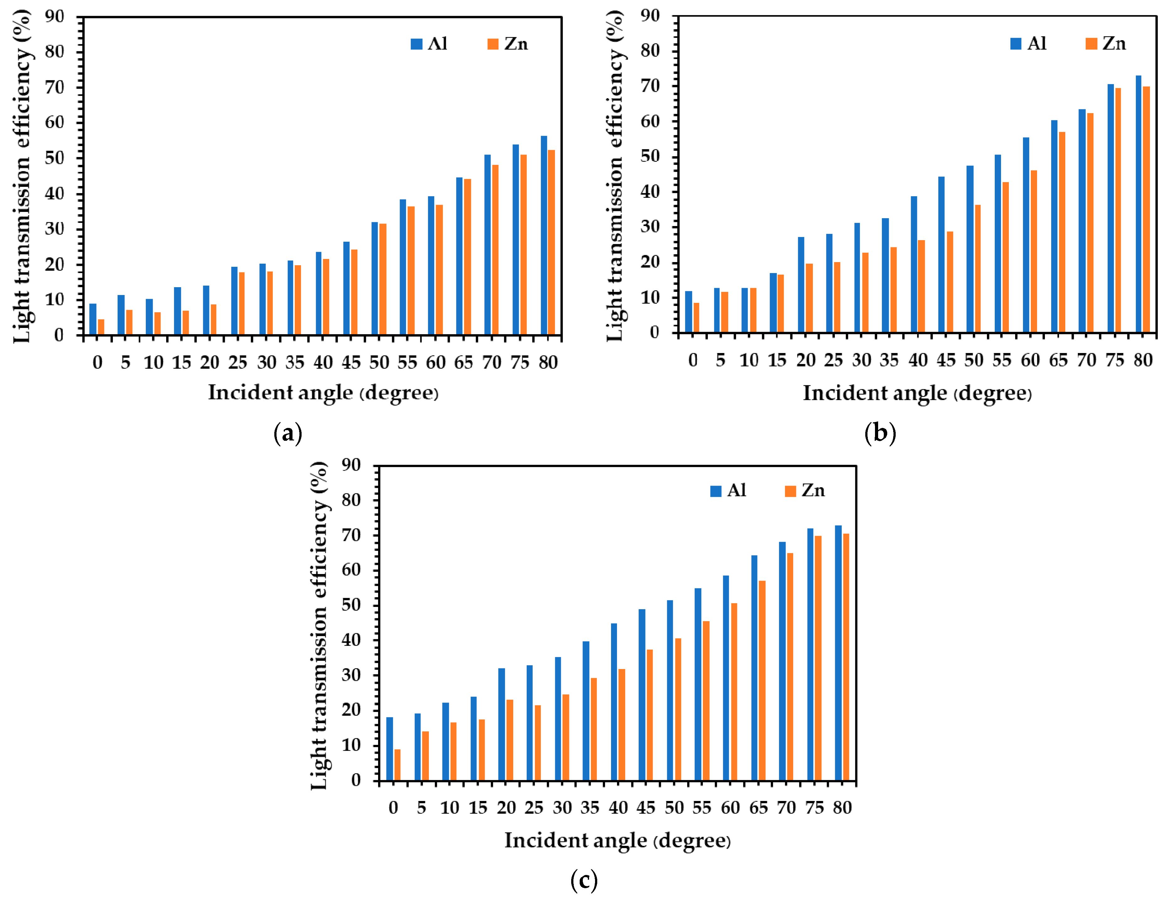
All of the luminous intensity values at the top and bottom ends of both aluminum alloy and zinc alloy tubes were considered to calculate the light transmission performance of the tubes, as exhibited in
Figure 10. Light transmission of the vertical aluminum alloy tube with a diameter of 0.20 m increased from 9.1% to 56.3% when the incident light angle to the tube increased from 0° to 80°, as shown in
Figure 10a. When considering the diameters of 0.25 m and 0.30 m, the light transmission performance was similar to those of the 0.20 m diameter tube, as illustrated in
Figure 10a. Light transmission performance of the aluminum alloy tubes with a diameter of 0.25 m increased between 11.8% and 73.3%, and that of the 0.30 m tube increased from 18.3% to 73.1% when the incident light angle increased from 0° to 80°.
When using the zinc alloy tube with a diameter 0.20 m and a height of 0.50 m, light transmission increased from 4.7% to 52.5% when the incident light angle increased from 0° to 80°. For the diameters of 0.25 m and 0.30 m, the light transmission performance was similar to those of the 0.20 m diameter tube, as illustrated in
Figure 10b. Light transmission performance of the zinc alloy tube with a diameter of 0.25 m increased between 8.7% and 69.9%, and that of 0.30 m tube increased between 9.1% and 70.6% with an increase of the incident light angle from 0° to 80°. This increase of light transmission performance is achieved from an increase of the incident light angle, demonstrating the reduced number of reflections within the light tube surfaces, which leads to minimal losses of luminous intensity.
Additionally, when using the aluminum alloy tube with a height of 0.5 m and diameters of 0.20 m, 0.25 m, and 0.30 m, the light transmission increased from 9.1% to 18.3% with an increase of the tube diameter from 0.20 m to 0.30 m at the incident light angle of 0°. The light transmission performance at the incident light angles of 5°, 10°, 15°, 20°, 25°, 30°, 35°, 40°, 45°, 50°, 55°, 60°, 65°, 70°, and 80° were similar to those of the incident angle of 0°, as illustrated in
Figure 10a. For the case of the zinc alloy tube, the light transmission performance also increased from 4.7% to 9.1% when the tube diameter increased from 0.20 m to 0.30 m at the incident angle of 0°. At the incident light angles of 5°, 10°, 15°, 20°, 25°, 30°, 35°, 40°, 45°, 50°, 55°, 60°, 65°, 70°, and 80°, the light transmission performance also increased from 7.3% to 14.2%, 6.7% to 16.8%, 7.1% to 17.7%, 8.8% to 23.1%, 18.0% to 21.5%, 18.2% to 24.7%, 20.0% to 29.2%, 21.7% to 31.8%, 24.2% to 37.4%, 31.5% to 40.6%, 36.5% to 45.6%, 36.8% to 50.7%, 44.2% to 57.2%, 48.3% to 65.1%, 51.1% to 69.9%, and 52.5% to 70.6%, respectively, as exhibited in
Figure 10b. This demonstrates that higher diameters of aluminum alloy and zinc alloy light tubes lead to an increase in light transmission performance, relating to less losses of luminous intensity that occur from the decrease in the number of reflections in the inner tube surfaces.
With comparing the aluminum alloy tube and zinc alloy tube of the same diameter, average light transmission performance of the aluminum alloy tube was higher than that of zinc alloy tube in each incident light angle and diameter of light tube, as shown in
Figure 11. It was observed that the average light transmission performance of the aluminum alloy tube can transmit the luminous intensity more than 4% when compared with that of zinc alloy tube in all conditions. This demonstrates that the aluminum alloy tube shows more reflectivity than zinc alloy tubes. This indicates that this technology could be considered as an alternative daylight system in deeper rooms or could substitute artificial lighting in windowless spaces, leading to greater energy conservation in buildings.
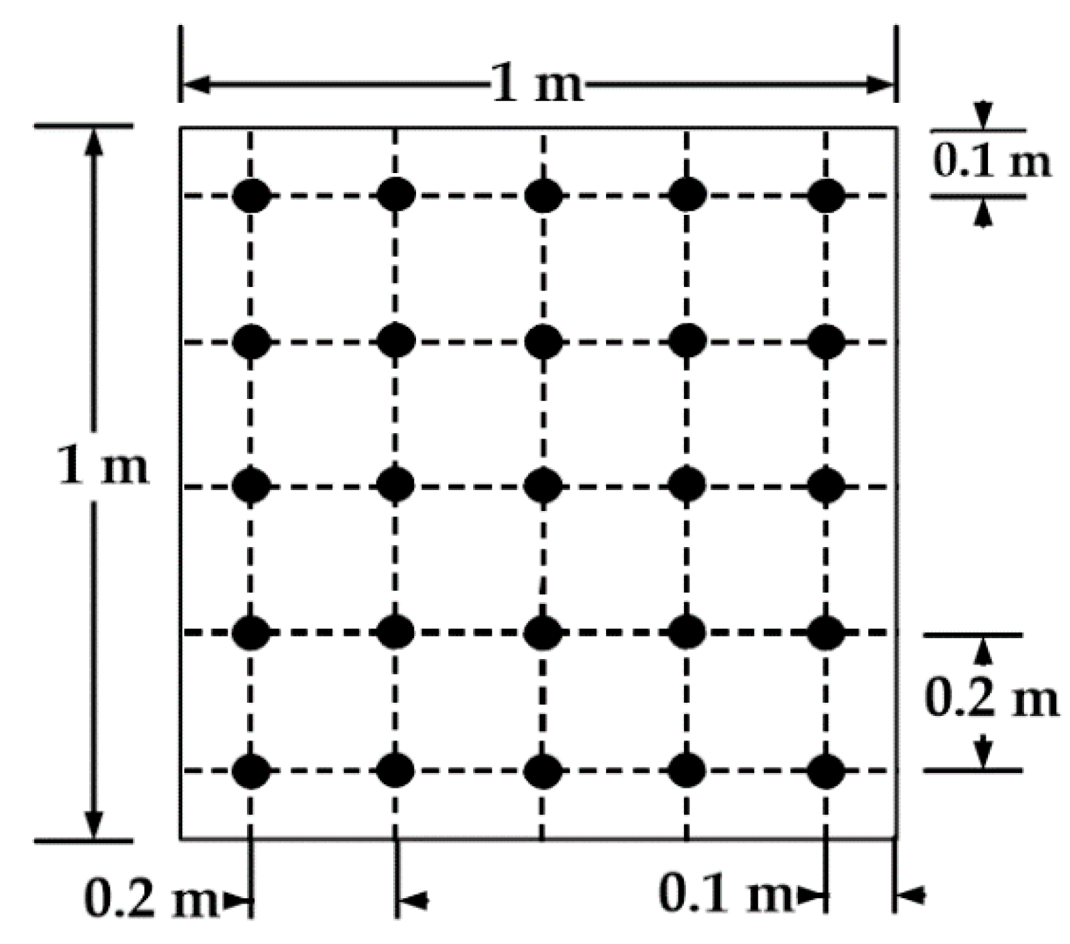
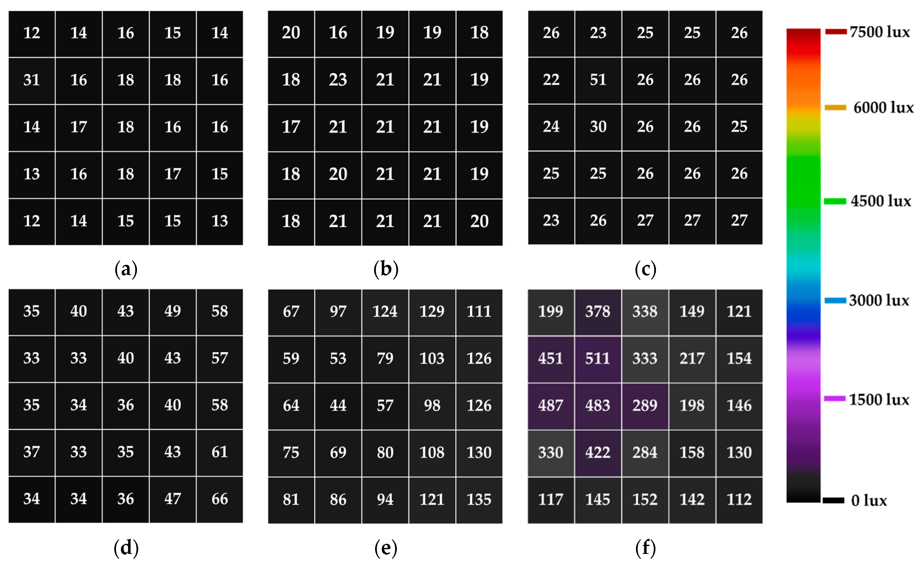
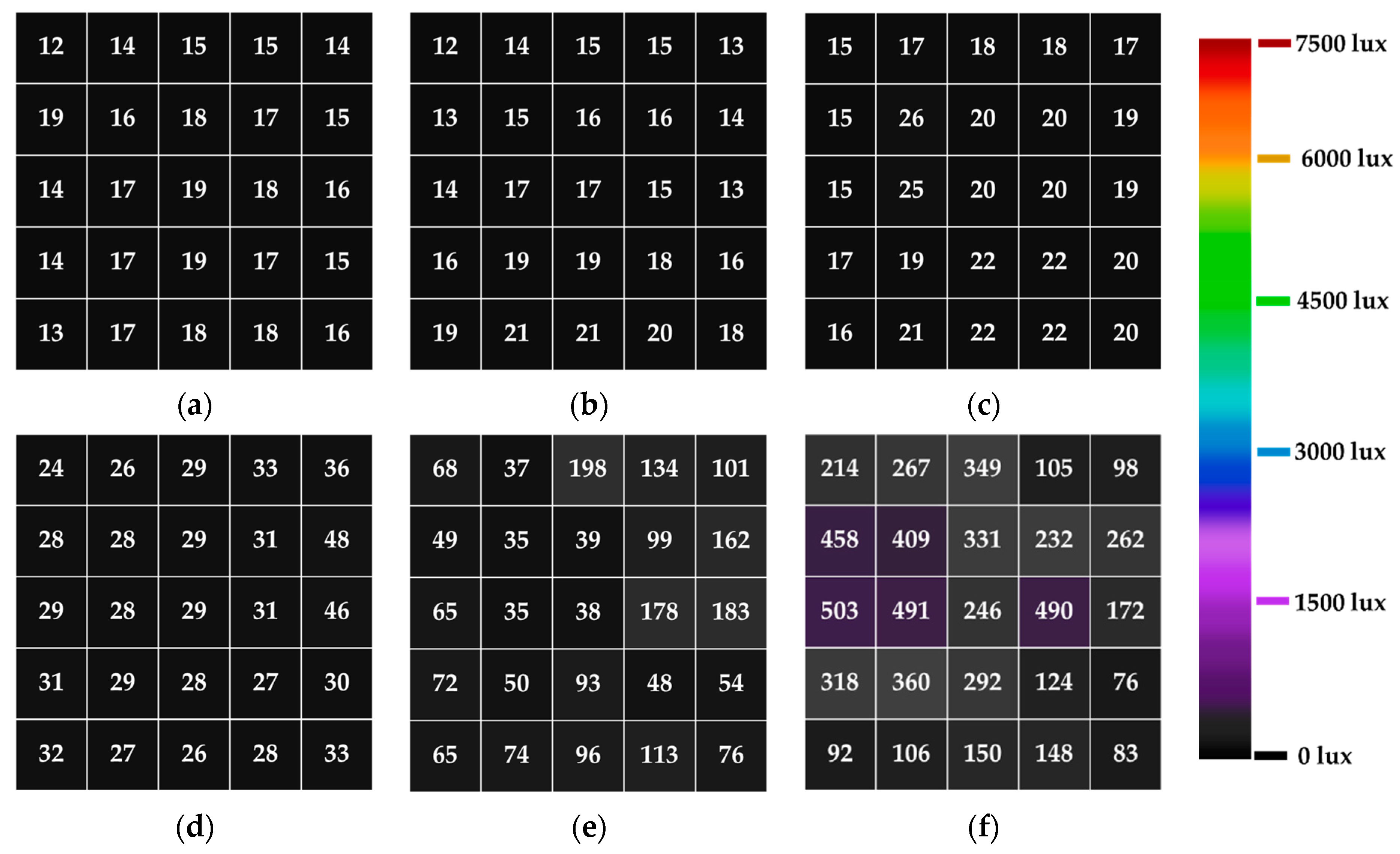
The illumination distribution on the floor of the model room from the aluminum alloy and zinc alloy light tubes, with a diameter of 0.25 m and a tube height of 0.5 m, are presented in a 2-D color map as exhibited in
Figure 12 and
Figure 13. The illuminance distribution from the aluminum alloy was between 12 lux and 31 lux, and the zinc alloy light tube was between 12 lux and 19 lux, at the incident light angle of 0°. When the incident angle increased from 0° to 45°, the illuminance distribution on the floor from both types was uniformly distributed at the same value throughout. When the incident light angle increased from 45° to 80°, the internal illuminance distribution was nonuniformly distributed, as shown in
Figure 12d–f and
Figure 13d–f. When the incident angle increased from 0° to 80°, a higher illuminance in each position was achieved, as shown in
Figure 12 and
Figure 13.
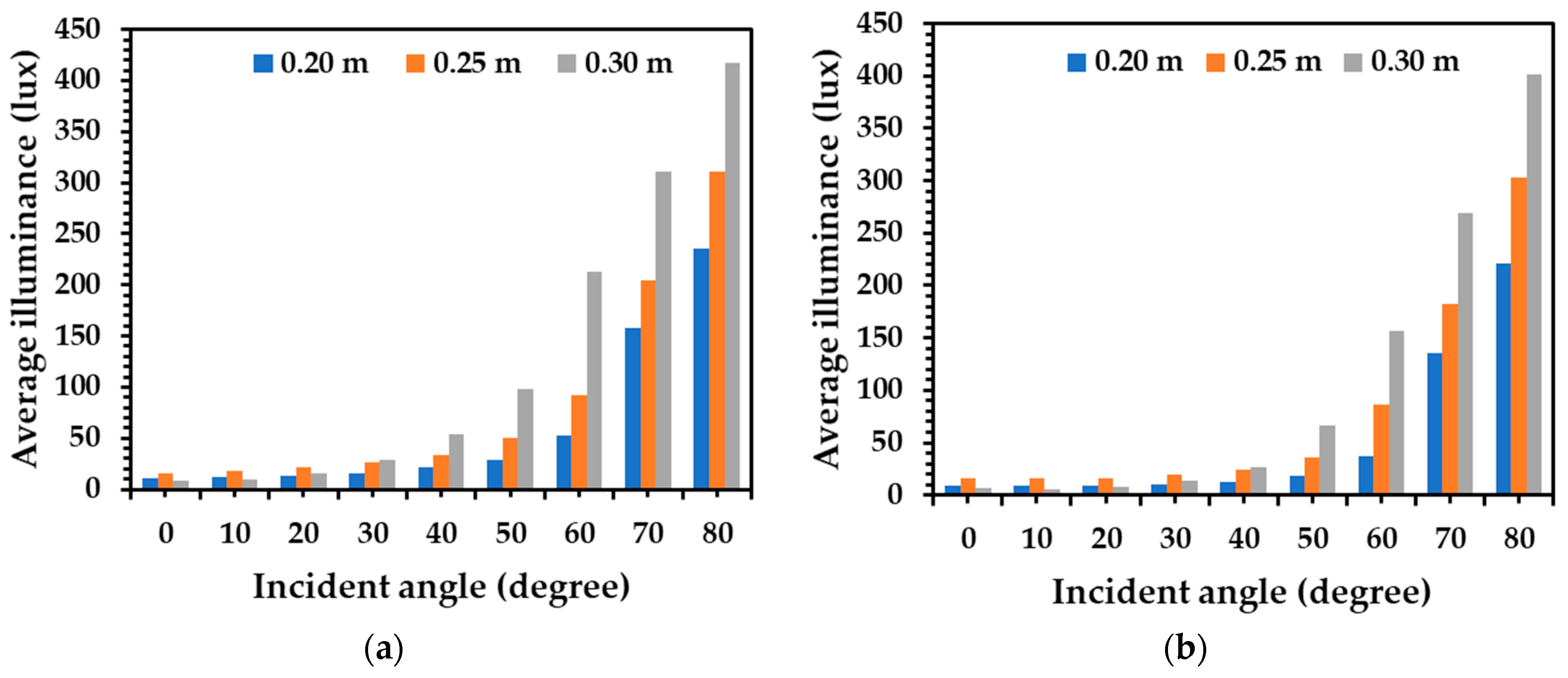
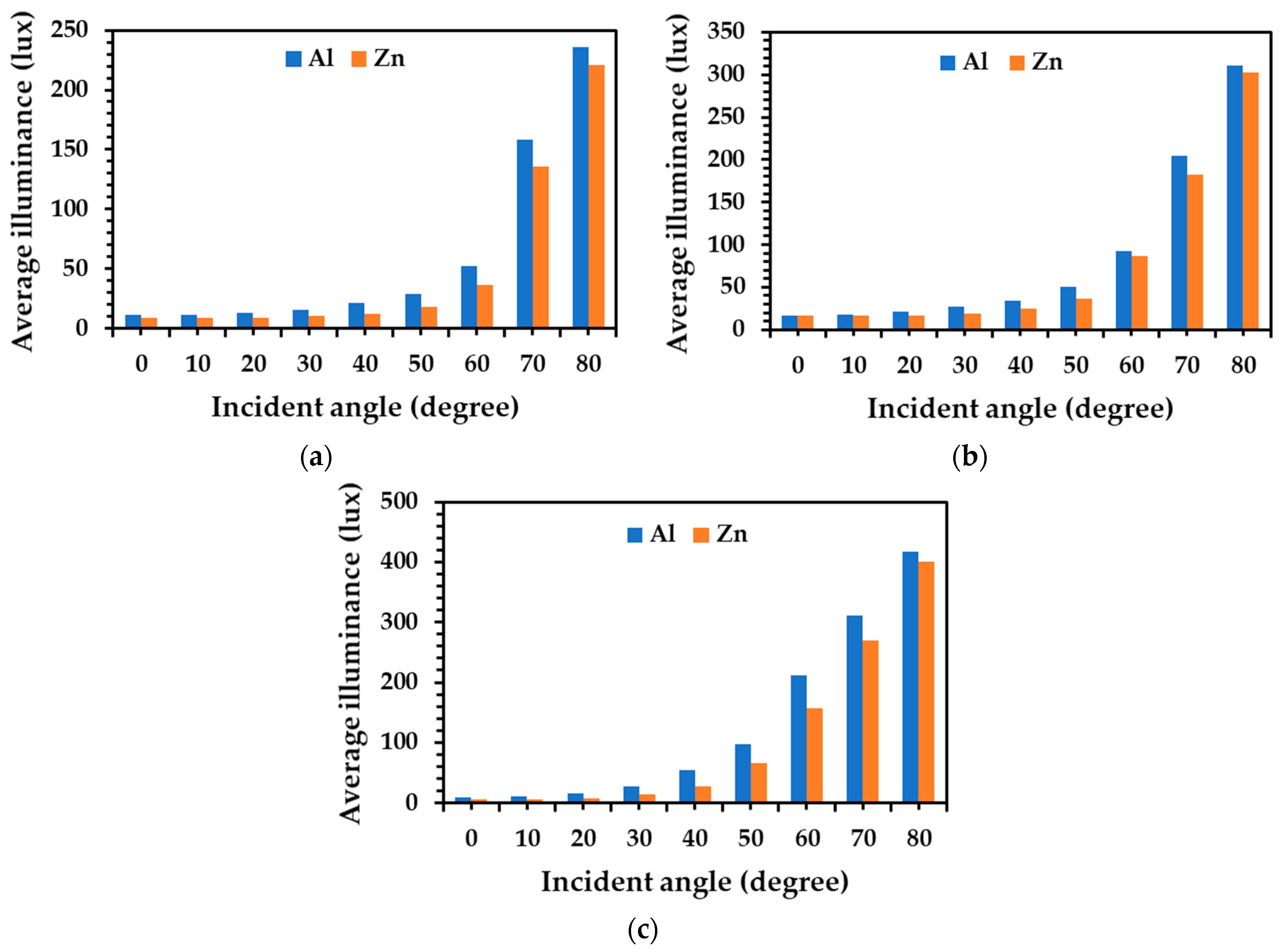
The 25 positions of illumination measurements on the floor were averaged for both aluminum and zinc alloy light tube with a length of 0.5 m and different diameters (0.20 m, 0.25 m, and 0.30 m) as exhibited in
Figure 14 and
Figure 15. When considering the aluminum alloy tube, with a diameter of 0.20 m, the average illuminance on the floor increased from 11 lux to 236 lux when the incident angle increased from 0° to 80°. For the cases of the diameters of 0.25 m and 0.30 m, the average illuminance values on the floor were similar to those of the 0.20 m diameter tube, as illustrated in
Figure 14a. The average illuminance on the floor with the aluminum alloy tube with a diameter of 0.25 m increased between 16 lux and 311 lux, and that of 0.30 m increased between 9 lux and 418 lux when there was an increase in the incident light angle from 0° to 80°.
When considering the zinc alloy tube with a diameter of 0.20 m, the average illuminance on the floor increased from 9 lux to 20 lux when the incident light angle increased from 0° to 80°. For the cases of the diameters of 0.25 m and 0.30 m, the average illuminance values on the floor were similar to those of the 0.20 m diameter tube, as illustrated in
Figure 14b. The average illuminance on the floor with the zinc alloy tube with a diameter of 0.25 m increased between 16 lux and 302 lux, and that of the 0.30 m diameter tube increased between 6 lux and 400 lux when there was an increase in the incident angle from 0° to 80°.
Comparing the diameter of both aluminum alloy tubes and zinc alloy tubes, the average illuminance on the floor was between 9 lux to 28 lux when the tube diameter increased from 0.20 m to 0.30 m at the incident light angles of 0°, 5°, 10°, 15°, 20°, 25°, and 30°. For the incident light angles of 35°, 40°, 45°, 50°, 55°, 60°, 65°, 70°, and 80°, the average illuminance on the floor of both aluminum alloy tube and zinc alloy tube increased with an increase in diameter from 0.20 m to 0.30 m, as illustrated in
Figure 14.
Comparing the aluminum and zinc alloy tubes at the same diameter of 0.20 m, the average illuminance on the floor from the aluminum alloy tube was higher than that of zinc alloy tube at all incident light angles, as shown in
Figure 15a. The aluminum alloy tube was more than 7% brighter when compared with zinc alloy tubes at incident light angles between 0° and 80°. For the diameters of 0.25 m and 0.30 m, an increase of the average illuminance on the floor from the aluminum alloy tube was more than 3% when compared with that of zinc alloy tube at all incident light angles, as shown in
Figure 15b,c. This indicates that the aluminum alloy tube has more illuminance efficiency than zinc alloy tubes at each diameter size and incident light angle.
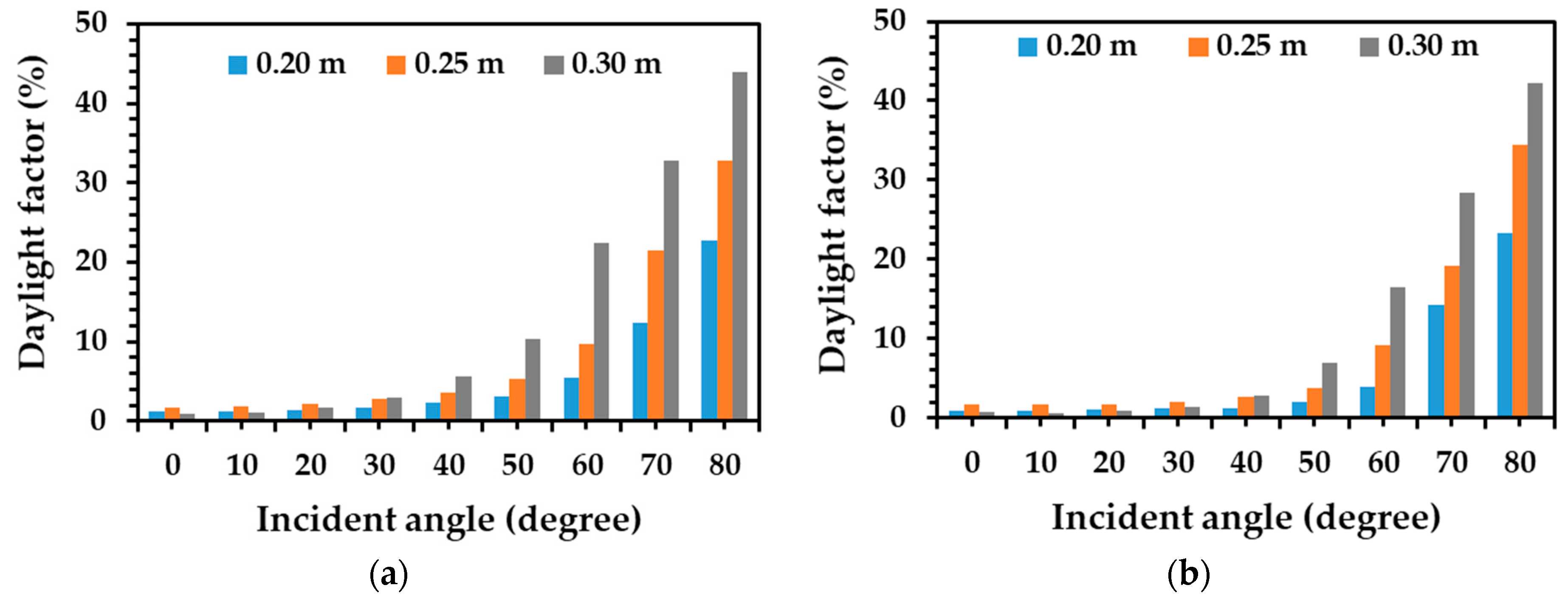
The daylight factor is defined as the average internal illumination on the floor plane and illuminance on the external testing model in an unshaded area. The exterior illuminance was measured to be between 890 lux and 1140 lux and obtained an average luminous intensity of 950 lux. The daylight factor for both aluminum alloy and zinc alloy light tubes in all patterns is demonstrated in
Figure 16. When considering the aluminum alloy tube with a diameter of 0.20 m, the average daylight factor increased from 1.2% to 22.7% when the incident light angle increased from 0° to 80°. For the cases of the diameters of 0.25 m and 0.30 m, the average daylight factor was similar to those of the diameter of 0.20 m as displayed in
Figure 16a. The average daylight factor from the aluminum alloy tube with a diameter of 0.25 m increased between 1.6% and 32.7%, and that of 0.30 m increased between 0.9% and 43.9% when there was an increase of incident light angle from 0° to 80°.
Considering the case of the zinc alloy tube with a diameter 0.20 m, the average daylight factor increased from 0.9% to 23.2% with an increase in the incident light angle from 0° to 80°. For the cases of the diameters of 0.25 m and 0.30 m, the trend of average daylight factor was similar to those of the diameter of 0.20 m, as exhibited in
Figure 16b. The average daylight factor from zinc alloy tube with a diameter of 0.25 m increased between 1.7% and 34.5%, and that of 0.30 m increased between 0.7% and 42.2% when there was an increase of incident light angle from 0° to 80°. When comparing the incident light angle to the tube of both aluminum alloy tube and zinc alloy tube, the average maximum daylight factor was found at the incident light angle of 80° from both aluminum alloy tubes and zinc alloy tubes.
Comparing the diameter variation of both aluminum alloy tubes and zinc alloy tubes, the daylight factor was similar and between 0.7% and 2.9% when the tube diameter increased from 0.20 m to 0.30 m at the incident light angles of 0°, 5°, 10°, 15°, 20°, 25°, and 30°. For the incident light angles to the tube of 35°, 40°, 45°, 50°, 55°, 60°, 65°, 70°, and 80°, the daylight factor of both aluminum alloy tube and zinc alloy tube increased with an increase in diameter from 0.20 m to 0.30 m, as illustrated in
Figure 16. This observation demonstrated that the aluminum alloy tubes can provide a better daylight factor compared with zinc alloy tubes for each condition.
This daylight factor obtained from the aluminum alloy tubes and zinc alloy tubes in this work corresponded to those of previous works [
29,
31], which demonstrated the daylight contribution in areas with 1–2% of daylight factor for activities in residence and 2–4% of daylight factor for activities in office buildings [
29,
31]. For the case of window, the occupants visualize the outdoor environment and use natural ventilation, while the shading from adjacent obstacles and barriers appeared in many cases and insufficient daylight within deeper building areas was achieved. Skylights can provide high light intensity, natural ventilation, and uniform daylighting, but immoderate solar gains and overheating in the internal spaces of rooms was obtained. The distant areas in buildings achieved insufficient light transmission. Hollow light tubes in this work can transport daylight into some deeper or windowless areas of buildings and uniformly distribute light. Importantly, the investment price of this system was cheap for inventing the aluminum alloy tubes and zinc alloy tubes. Although an investigation of thermal behavior and inside illuminance of the models under natural weather conditions, and an analysis of the reduction of energy consumption using systems on a full scale could be led to more sound scientific knowledge for integrating the vertical light tubes into buildings; a more widespread context will be studied and analyzed under natural weather conditions in the future work. In view of the benefits, the invented light tubes can use commercial aluminum alloy sheets and commercial zinc alloy sheets to provide illumination for activities in residences and offices for some incident light angles for each diameter of light tube, which leads to an alternative inexpensive material for producing a lighting system. This investigation could be considered as an alternative daylight system in deeper parts of buildings or the windowless spaces to conserve the energy consumption for lighting buildings.


