Article

A DCM Single-Controlled Three-Phase SEPIC-Type Rectifier

Power Electronics and Drives Laboratory, Department of Electrical Engineering, Federal University of Espírito Santo, Vitória, ES 29075-910, Brazil
*
Author to whom correspondence should be addressed.
Energies 2021, 14(2), 256; https://doi.org/10.3390/en14020256
Submission received: 14 October 2020 / Revised: 2 December 2020 / Accepted: 15 December 2020 / Published: 6 January 2021
(This article belongs to the Section A1: Smart Grids and Microgrids)

Abstract

:
A discontinuous conduction mode (DCM) three-phase single-ended primary-inductor converter (SEPIC) is presented in this article. The analyzed converter operates as a high-power factor stage in AC–DC conversion systems. As its main features, it presents three controlled switches and a single control signal with simple implementation and low-current harmonic distortion. The converter topology, its design equations, and its operation modes are presented as well as a simulation analysis considering a 3 kW–220 V three-phase input to 400 V DC output converter. The experimental results are included, considering as an application the rectifier stage in low-power wind energy conversion systems (WECS) based on a 1 kW permanent magnet synchronous generator (PMSG) with variable voltage frequencies. From the analysis performed in the paper and the simulation and experimental results revealed, it is concluded that the converter is indicated to be employed in any AC–DC low-power conversion system, such as DC distribution systems, and distributed generation or hybrid systems containing variable-frequency generation.

1. Introduction

AC–DC conversion is present in much modern electronic equipment. Widespread distribution systems are AC, and consumer goods are increasingly employing DC sources to feed even AC loads, such as washing machines and air conditioners.
In order to not disturb grid voltage, the current waveform should present restricted harmonic content. The behavior of an AC–DC stage must approach a perfect linear load. High-power-factor rectifiers are AC–DC converters that present low total harmonic distortion (THD).
Even for a DC microgrid, which has received great attention in recent years [1,2,3,4,5,6], AC–DC conversion can perform important tasks. A typical configuration of such an approach is shown in Figure 1. It is noticed that it encompasses some renewable electrical and conventional resources as well as an AC grid connection. Microturbines and wind turbines also require AC–DC conversion.
For a three-phase source, many topologies are presented in the literature. Six controlled switch converters are effective for high power levels, but when it comes to systems with lower power levels, where only unidirectional power flow is required, rectifiers with a reduced number of active elements (single or three controlled switches) operating in the DCM are usually preferred, and the three-phase boost is the most used [7,8,9,10,11,12]. A variety of solutions has recently arisen [13,14,15,16,17,18,19,20,21,22]. In the analysis of the power conversion from the grid to DC bus, the input RMS voltage is almost constant, maintained in the range given by standards. The design of the control loop focuses on the DC bus voltage.
On the other hand, in wind power generation systems, the output power is related to wind speed. Variable-speed PMSG-based microwind turbines at the sub-kW level have been employed for residential and small commercial buildings, where for battery charging, an isolated converter is required for grid interfacing [23].
A simple, cost-effective, and higher-power-density solution applied to low power with uncontrolled devices is presented in the literature, such as [24], where discontinuous conduction mode (DCM) rectification is performed by a bridge rectifier diode. A configuration where a rectifier diode plus a DC–DC boost converter is used in the DCM is presented by the authors of [25,26], and the author of [27] presents a configuration operating in the continuous conduction mode (CCM). This solution, however, presents a typical distorted generator current waveform that leads to a pulsating generator active power. An advantage of this structure reported by the authors of [28] is to control the power provided by the PMSG through a single PWM signal, which negatively does not allow a separated id and iq control and extraction of the maximum power of the generator. Some drawbacks have been reported [29], mainly due to high harmonic current distortions in the generator windings, such as: increasing heating, reduction in machine efficiency, and the production of high-torque ripples due to the use of a diode-bridge rectifier [30].
To alleviate these problems, DCM boost rectifiers have been considered [7,25,31,32,33]. For operation in DCM, an input filter is required for smoothing the high-frequency input current. These solutions still present an important level of low-order harmonics flowing into the generator, resulting in a pulsating power of low frequency, causing power fluctuations, as shown in Figure 2a,b, which show one phase input voltage and current after filtering and electric power drained from the source, respectively. To effectively use available wind energy, the current drawn from the generator should be an image of the generated voltage.
This work presents a high-power-factor DCM rectifier topology able to be used in the grid-connected rectification stage as well as the interface topology of low-power AC generators. The converter employs three controlled switches but only one single gate signal and has as a great advantage the ability to drain a current from the AC source that is an image of the voltage despite the input voltage value, with no current control loop and low-current ripple, absorbing almost constant electric power from the AC source. A differential achievement is that the converter can operate with an output voltage value near the input voltage (peak line value), bringing low-torque oscillations to the machine and almost constant output power.

2. Proposed Converter

The proposed converter is shown in Figure 3. The generator inductance is incorporated as its input inductor, represented with the same inductance L1 for each phase since the converter is a symmetrical three-phase topology. It uses three IGBTs plus reverse diodes (or three MOSFETs). Thus, conduction losses, proportional to the voltage drop in the current path, are reduced. This is an important improvement during this stage, especially at low power.
The topology operates with an output voltage greater than the peak of the line input voltage. The three controlled switches (IGBTs with antiparallel diodes or MOSFETs) are connected to a common point and driven by the same signal. One single gate control is required, reducing its complexity and providing greater robustness to the conversion system. The three-phase SEPIC-type rectifier is indicated for applications where the output voltage is higher but close to the peak voltage in the condition that maximum voltage is generated.
A remarkable feature of this converter is that it provides an input current in phase with the voltage, presenting a high power factor and low harmonic content, as will be detailed further. A notable advantage in this regard is that in order to operate with a high-power factor, there is no need to control the input currents once they naturally remain in phase with the input voltage.
From the point of view of the AC source, the SEPIC-type topology acts as a three-phase loss-free resistor [34]. Compared with commonly used topologies, such as the six controlled switches topology mentioned before, which, in order to operate with a power factor close to the unit value, the converter requires a closed-loop current control, the proposed converter presents an excellent benefit. Another advantage of the proposed converter is the reduction in cost since the number of active elements is smaller (compared with topologies with a similar power level using six controlled switches).

2.1. SEPIC-Type Rectifier Operation Principle

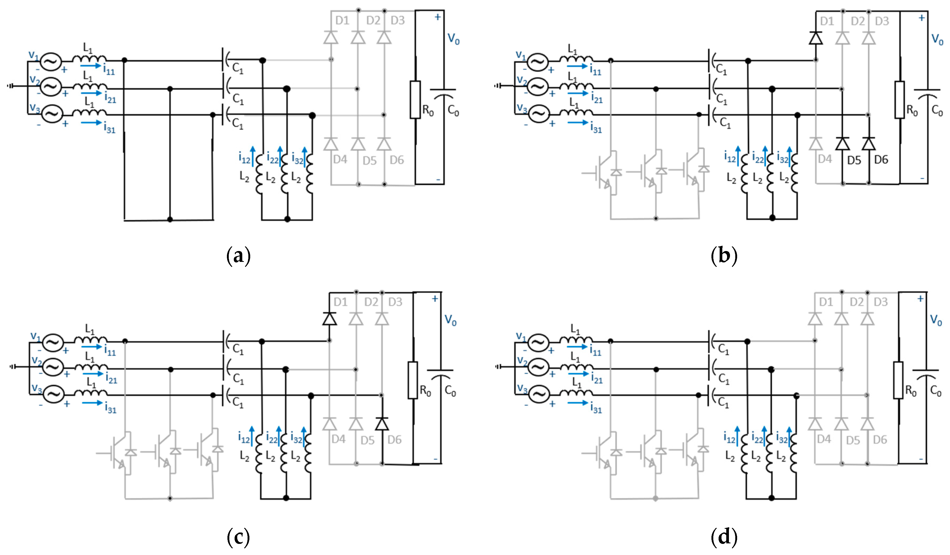
In the following analysis, the AC source is considered, generating three symmetrical voltages: v1, v2, and v3 (positive sequence with v1 as reference). Input voltages as well as the voltages in series capacitors (three capacitors with the same capacitance C1 because of the symmetrical three-phase topology) are considered constant in a switching period, and the voltages in these capacitors follow the respective phase voltages over a period. The operation of this converter can be understood by dividing its operation into three stages: connected switches, disconnected switches, and freewheeling operation. Each of these steps is qualitatively described below in the interval from 0° to 30° (v1 > 0, v2 < 0, v3 < 0).

2.1.1. First Stage—Switches Turned on (ton)

During turned-on time (ton), the same trigger signal is applied to all three switches. The resulting circuit is shown in Figure 4a. The phase voltages are applied to the inductors since the voltages in the capacitors follow the input voltages. For positive voltages, the currents in the inductors increase in value from the freewheeling values, whereas for negative voltages, the currents in the inductors grow negatively. In this step, as the inductor voltages are the input voltages, diodes are reverse-polarized and do not conduct. From the analysis of this stage, an operating condition is defined: the output voltage V o must be greater than V e 3 , where V e is the peak value of the phase voltage at the input. If this condition, which must be guaranteed in the design of the converter, is not satisfied, some output diodes are directly polarized and a short circuit, involving the output voltage and capacitors C1, will occur. An output voltage lower than V e 3 is possible by using coupled inductors such as L2 (the same three-phase inductance L2). This stage lasts for ton = dTs, where d is the duty cycle and Ts is the switching period.

2.1.2. Second Stage (tdon1)

When the switches are turned off, the output diodes are directly polarized, and the energy stored in L1 is transferred to series capacitors C1 and C0 (output capacitor). The energy stored in L2 is transferred to the output (C0). The equivalent circuit is shown in Figure 4b. Currents decrease linearly (in absolute value) until the smallest current reaches the value of the freewheel.

2.1.3. Third Stage (tdon2)

The remaining inductor currents decrease until all currents reach freewheeling, as shown in Figure 4c.

2.1.4. Fourth Stage—Freewheeling (toff)

At this stage (Figure 4d), the currents do not pass through any semiconductor. The existence of this stage characterizes the DCM operation, and it ends when the controlled devices are reconnected.
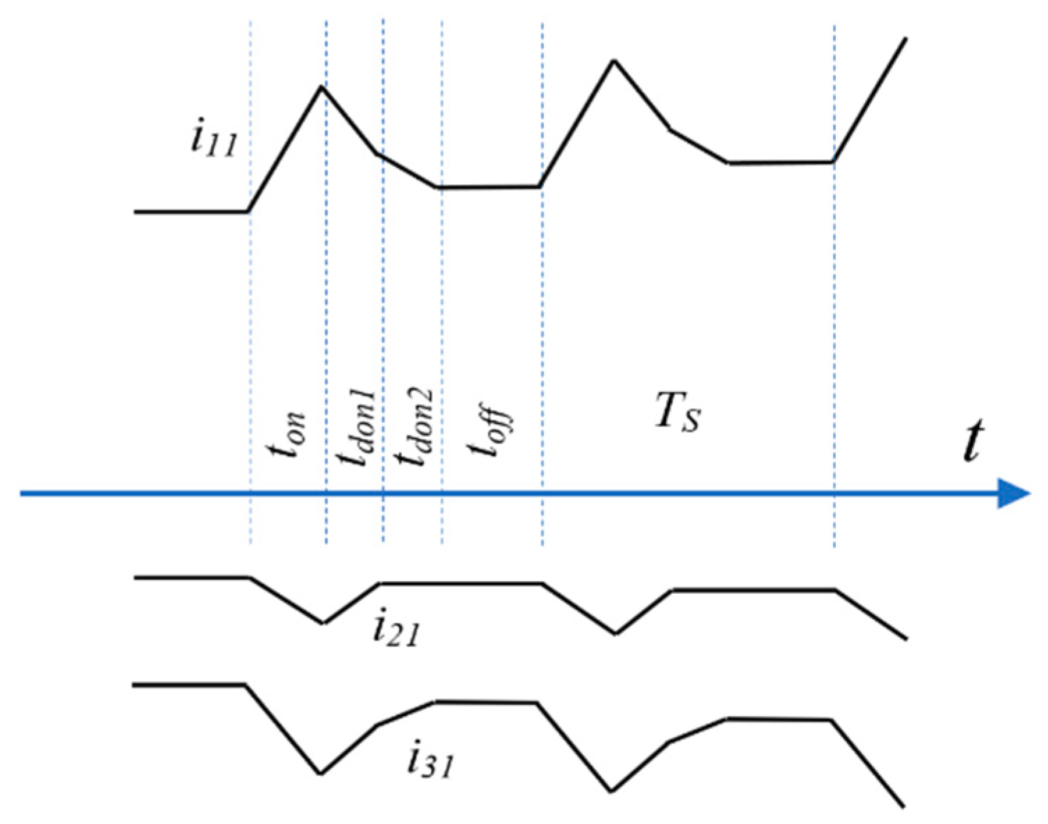
Input currents in a few switching periods and respective time intervals are shown in Figure 5, where i11, i21, and i31 are the currents in the inductors L1 of Phases 1, 2, and 3, respectively.

2.2. Theoretical Converter Analysis

The equations describing the converter behavior are presented below. In the following equations, as a balanced three-phase converter, input inductors have the same value and are presented as L1; coupled inductors for each phase are presented as L2, and series capacitors are presented as C1. Additionally, i11, i21, and i31 are the currents in the inductors L1 of Phases 1, 2, and 3, respectively, and i12, i22, and i32 are the currents in the L2 inductors of Phases 1, 2, and 3, respectively. Freewheeling currents are represented as i 1 , rl , i 2 , rl , i 3 , rl for each phase. As presented before, the three symmetrical voltages are v1, v2, and v3 and the output voltage is Vo.
It is important to notice that the voltage at the common point of the IGBT connection, although not physically connected to the ground, presents the same potential (usually considered zero). This can be explained by applying Kirchhoff’s current law to that point (currents sum is zero) and due to the fact that the source voltages are symmetrical (their sum is also zero).
The first stage lasts for ton = dTs, where d is the duty cycle and Ts is the switching period. Through the application of Kirchhoff’s laws along the equivalent circuits in this stage, for Phase 1, it can be seen that:
v 1 + L 1 di 11 dt = 0 v 1 + L 2 di 12 dt =   0
i 11   =   v 1 L 1 t   + i 1 , rl i 12   =   v 1 L 2 t   i 1 , rl  
Similarly to Phases 2 and 3:
i 21   =   v 2 L 1 t + i 2 , rl i 22   =   v 2 L 2 t     i 2 , rl
i 31   =   v 3 L 1 t + i 3 , rl   i 32 =   v 3 L 2 t   i 3 , rl
Analysis for the second stage on inductors L1 is shown from (5) to (10).
v 2   +   L 1 di 21 dt   +   v 2   v 3   L 1 di 31 dt + v 3   =   0
di 31 dt   =   di 21 dt
v 1 + L 1 di 11 dt + v 1 +   V o + v 3 L 1 di 31 dt   v 3   =   0  
di 31 dt     di 11 dt = V o L 1  
It is a fact that:
i 11 + i 21 + i 31 =   0  
It is important to note that this step lasts until the current of the lowest absolute value, in this case i21, reaches the freewheel value. Then:
i 21   = V o 3 L 1 t   + v 2 dT s L 1 + i 2 , rl = i 2 , rl
The duration of the second stage (tdon1) is shown in (11), where M is the ratio between the output voltage (Vo) and Ve.
t don 1   = 3 dT s cos ( ω t   +   60 ) M
For the third stage, the current i21 is already freewheeling, lasting until the others reach the freewheeling value. Analyzing the L1 inductors, the following equations can be written.
i 21 = i 2 , rl     di 21 dt =   0
di 11 dt + di 31 dt =   0  
Substituting previous equations:
di 11 dt =   V o 2 L 1 i 11 =   V o 2 L 1 t   +   ( V o 3 L 1 t don 1   + v 1 dT s L 1 + i 1 , rl )
i 21 = i 2 , rl
di 31 dt = V o 2 L 1 i 31   = V o 2 L 1 t   +   ( 2 V o 3 L 1 t don 1   + v 3 dT s L 1 + i 3 , rl )
To inductors L2, a similar analysis is performed.
i 22 = i 2 , rl     di 22 dt =   0  
di 12 dt + di 32 dt =   0  
Substituting previous equations:
di 12 dt =   V o 2 L 2       i 12 =   V o 2 L 2 t   +   ( V o   3 L 2 t don 1 + v 1 dT s L 2     i 1 , rl )  
  i 22 = i 2 , rl  
di 32 dt   =   V o 2 L 2       i 32   = V o 2 L 2 t   +   ( 2 V o 3 L 2 t don 1   +   v 3 dT s L 2   i 3 , rl )  
The third stage lasts (tdon2), which is the time for i31 (along with i11) to become freewheeling.
i 31   = V o 2 L 1 t   +   ( V o 3 L 1 t don   +   v 3 dT s L 1   +   i 3 , rl )   =   i 3 , rl
t don 2   = 2 3 dT s M sin ( ω t )
In the last stage, all currents have reached the freewheeling value.
i 11 = i 12 = i 1 , rl
i 21 = i 22 = i 2 , rl
i 31 = i 32 = i 3 , rl
To ensure DCM operation, the switching period must be greater than the sum of the time of the first three intervals. Thus,
T s   dT s + 3 dT s   cos ( ω t + 60 ) M + 2 3 dT s M sin ( ω t )
Consequently, the maximum value that the duty cycle can assume is:
d   M M   +   3
The output current (I0) in the analyzed range is supplied by the converter during times tdon1, and tdon2 and corresponds to the sum of currents i11 + i12. Its mean value (I0) is provided by (29):
I 0   = 3 d 2 T s V e 2 4 VL eq
where Leq is the parallel equivalent of inductors L1 and L2 (30):
L eq = L 1 L 2 L 1 + L 2
The averaged output current (29) is a constant value for constant d and Ts. By doing this, the current injected at the output is guaranteed to be constant for all switching periods, meaning that the current at the input does not have low-frequency harmonic components.
From (4), a duty cycle for the proposed SEPIC-type converter can be selected in order to present DCM operation. Using (29), and considering rated power P, the equivalent converter inductance can be derived (31):
L eq = 3 d 2 T s V e 2 4 P
Considering the first stage (ton), the ripple current is dependent on power (P) and can be written as (32).
ripple ( % )   =   100 3 dT s V e 2 2 PL 1
Now, the L1 value is obtained by (32) and, using (30) and (31), L2 is derived.
The value of the capacitor of the converter must be calculated considering that the voltage at its terminals remains constant in the switching period; on the other hand, the voltage of the capacitor must follow the input voltage.
Analyzing the first step of operation, it is observed that the voltage in the capacitor varies little if the period of the resonance frequency between C1 and L2 is smaller than the ton interval. This prevents the capacitor from overdischarge. Thus, the first design criterion of the capacitor is given by (33):
C 1 > ( dT s ) 2 4 π 2 L 2
In addition, the smaller the value of C1, the greater the voltage ripple at its terminals and, consequently, the higher the voltage in the controlled switches and diodes.
On the other hand, the resonance frequency of the equivalent impedance seen by the grid must be significantly higher than the frequency of the grid so that there are no low-frequency oscillations. This requirement is satisfied according to (34):
C 1 < 1 ω 2 L eq
where ω is the grid frequency. Using the presented equations and performing the calculations, the values of the components are known.

3. Simulation Results

The proposed converter was designed and simulated considering a 3 kW–220 Vac/400 Vdc rectifier. The grid frequency is 60 Hz, whereas the switching frequency is 25 kHz. Using (28), the duty cycle is chosen as 0.4 (35). Through this value applied on (31), Leq can be calculated (36).
d = 0.4 0.56
L eq =   52   μ H
Assuming 20% of ripple in (32), inductors are calculated as L1 = 1.29 mH and L2 = 54 μH. Considering (33) and (34), 120 nF < C1 < 0.1 F. After some simulations, C1 = 10 μF was chosen.
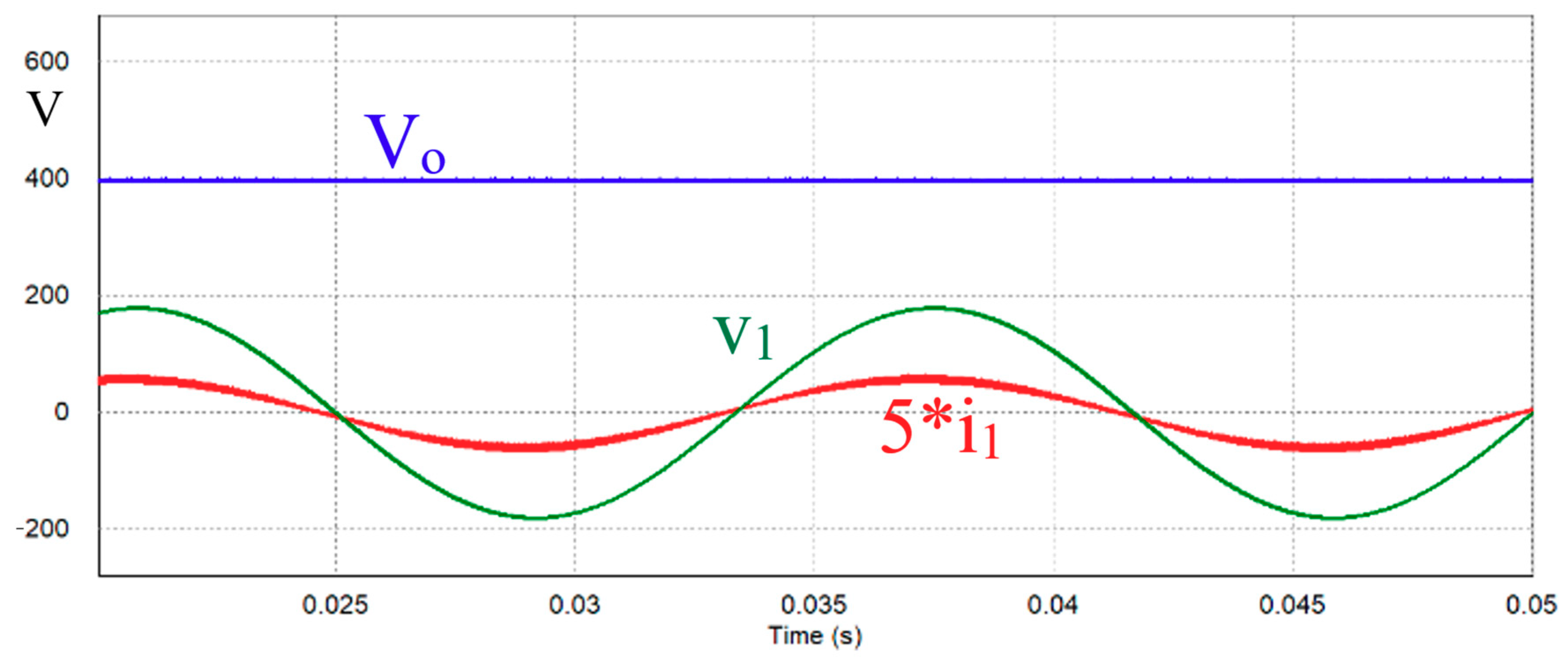
Figure 6 shows the output voltage Vo as well as input voltage (v1) and current (i1). The input current waveform is a mirror of the input voltage, except for the switching frequency ripple.
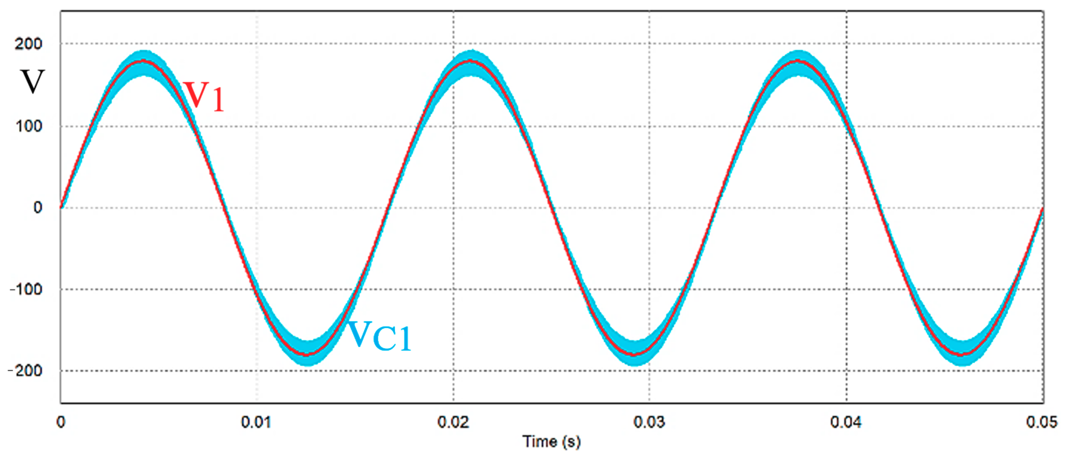
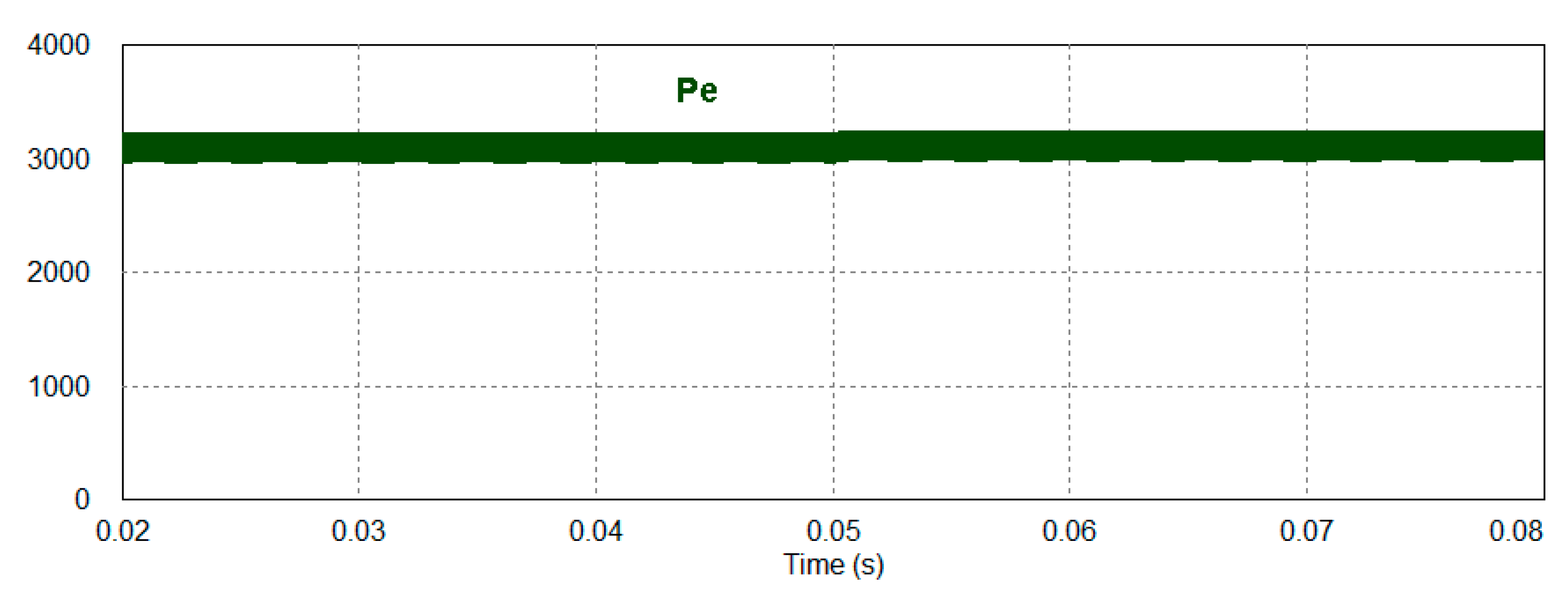
In Figure 7, the phase voltage (v1) and its respective capacitor voltage (vC1) are shown, which follow the input phase voltage. This is a characteristic of a SEPIC converter. The electric power absorbed from the source is shown in Figure 8. Opposite to the typical power absorbed from a single-switch three-phase boost rectifier (Figure 2), the absorbed power of this converter is constant without low-order harmonic oscillation.
A transfer function (TF) can be derived by applying small-signal perturbations into the average output current I0 (29). Cancelation of the steady-state terms results in a first-order TF, as given by (37). A comparison between the simulation result and TF estimation by applying a small step change into the duty cycle is performed. Figure 9a shows, for nominal conditions, the simulated output voltage (red) and the estimated output voltage by the transfer function (blue) when, at t = 0.05 s, the duty cycle is increased by 10%. Figure 9b shows a similar result for half load and a 10% duty cycle decrease. It can be concluded that the TF appropriately represents the dynamic converter behavior.
V o ^ d ^ = 3 D T s V e 2 2 V o L eq × R o R o C o s 2 + 1

4. Experimental Results

The rectifier topology presented was analyzed predicting an application to a low-power wind energy conversion system (WECS) based on a permanent magnet synchronous generator (PMSG) with variable wind speed. The SEPIC-type converter can operate for a wide wind speed range, keeping the DC bus voltage constant despite wind variations and consequent voltage and power variations at the input. For this analysis, the reduction in actual wind speed (vwind,actual) is considered compared to the nominal value (vwind,nominal) as nr, defined in (38),
n r = v wind , nominal v wind , actual
For a wind variation in a turbine whose nominal operating value is 12 m/s and a typical cut-in wind speed operation of 3 m/s, the variation between these values is ηr = 4. For this reduction, the generated voltage (which is proportional to the wind, according to Faraday’s law) is reduced by ¼ between the maximum and minimum values. The power, in turn, proportional to the cube of wind speed reduces by 1/64. Considering the output voltage constant, the M ratio increases as wind speed decreases. Considering (28), the duty cycle limit between the conduction–discontinuous operation increases. Thus, the limit of d, given by the nominal condition, is more restrictive than the condition for lower wind speed. Assuming an operation with d below the maximum for nominal condition, the DCM is maintained throughout the complete operating range. The relation between the duty cycle for rated wind speed (d) and any wind speed in the range (d′) can be obtained, as given by (39):
d =   d n r
A MPPT algorithm is usually employed to track the duty cycle according to wind variations.
The 3ϕ SEPIC-type converter was implemented considering a 1 kW power conversion system. The value used for L1 is a typical PMSG inductance value for this power, presenting a RMS line voltage of 220 V/40 Hz at 12 m/s nominal wind speed. The converter operates at a switching frequency of fs = 20 kHz, a DC bus of 400 V, and typical wind speeds (low and high speed) of 6 m/s and 12 m/s, resulting in voltage frequencies of 20 Hz and 40 Hz, respectively. The nominal duty cycle was chosen as 0.28. Table 1 shows the system specifications, and Table 2 presents the values of the specified components.
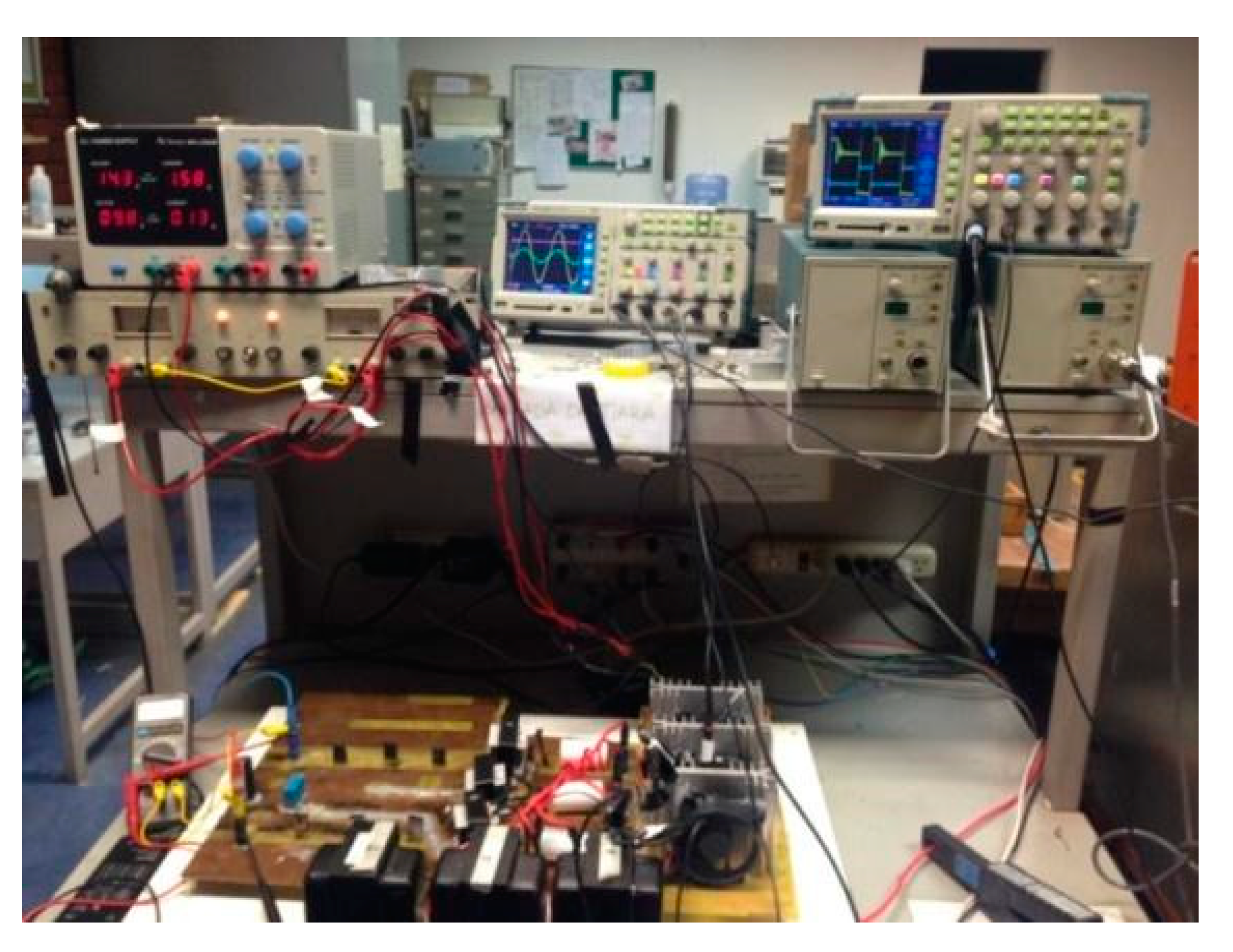
In order to emulate the output voltages of a wind generator, the programmable three-phase voltage source Pacific Power Source AMX-360 was used. The nominal power of the source is 6 kVA and allows effective voltages up to 338 V and frequency from 20 Hz to 5 kHz. The assembled workbench is shown in Figure 10. Table 3 presents the commercial components used.
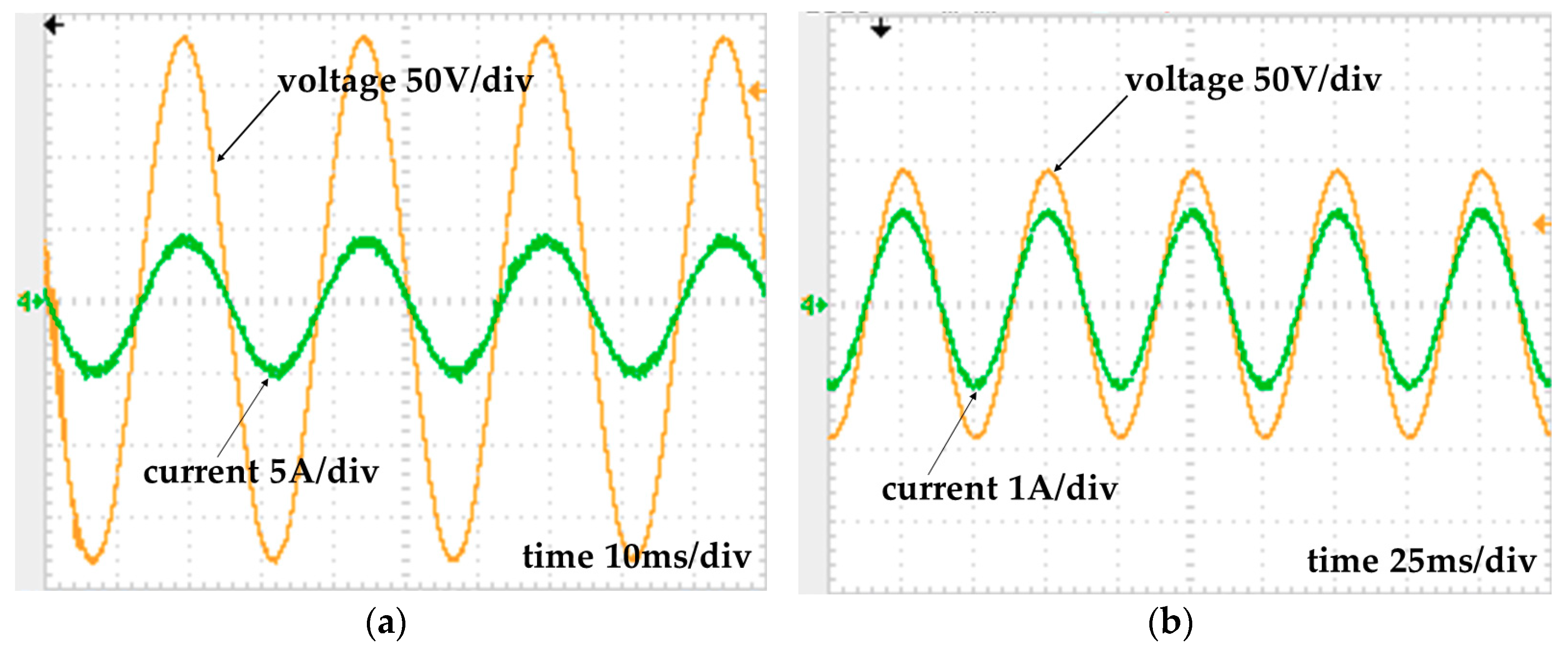
The results for the possible 12 m/s (40 Hz) and 6 m/s (20 Hz) wind operating points are presented. Figure 11a,b shows the current and voltage at the generator with operation at 40 Hz and 20 Hz, respectively.
One can observe the sine waveform of the current in phase with the voltage in both cases. For 40 Hz, the power factor value for Phase 1 provided in the Pacific Power source display was 0.998. The current THD supplied by the source (considering the odd-order harmonics) was 4.8%. For 20 Hz, the power factor value for Phase 1 provided in the Pacific Power source display was 0.993. The current THD supplied by the source (considering the odd-order harmonics) was 5.7%. Table 4 presents a summary of the converter operation with the data presented previously.
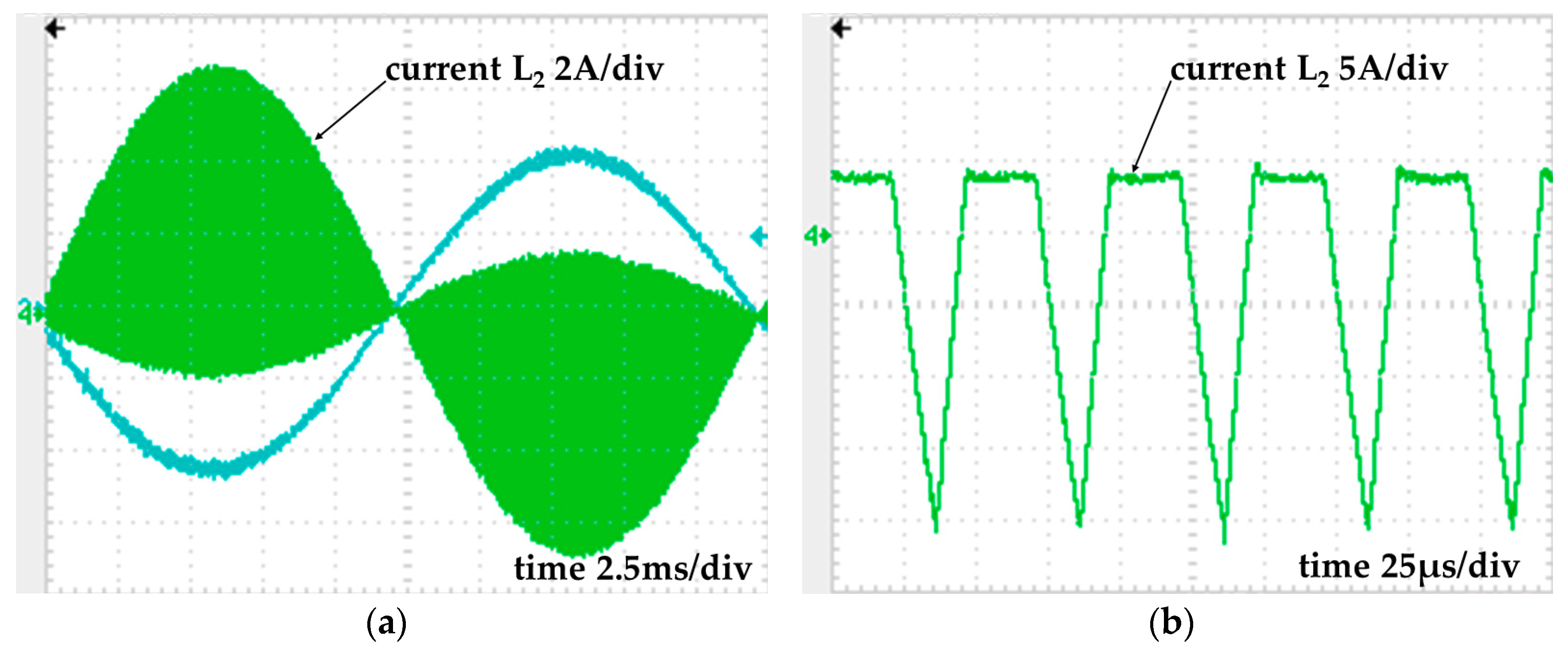
Figure 12a shows the image of current in L2 inductors for a 1/(40 Hz) period, and Figure 12b shows a zoom of the same current for some switching periods. The discontinuous conduction mode can be observed, characterized here as the time interval the current is constant (freewheeling).
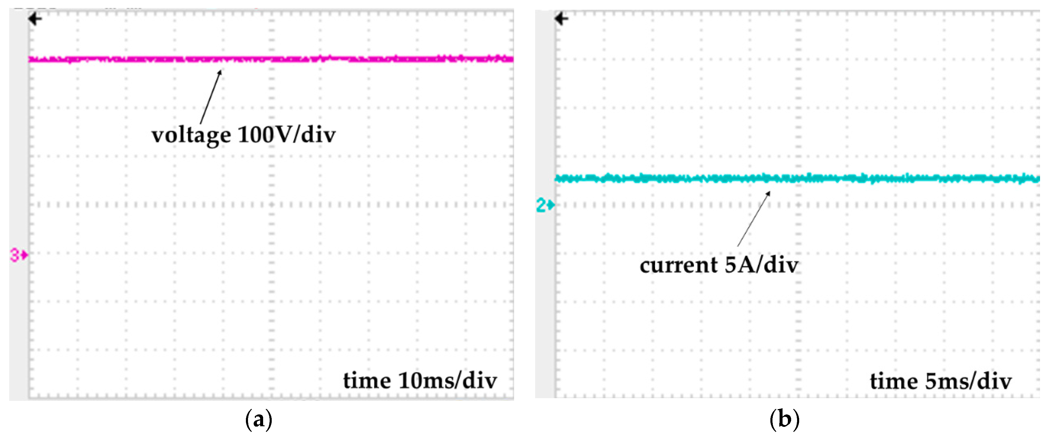
The output voltage (Figure 13a) and output current (Figure 13b) are shown for f = 40 Hz (vwind = 12 m/s). It can be noticed that the voltage ripple is negligible. For the connected load, the voltage reaches around 400 V, and the current reaches an average value of 2.67 A.
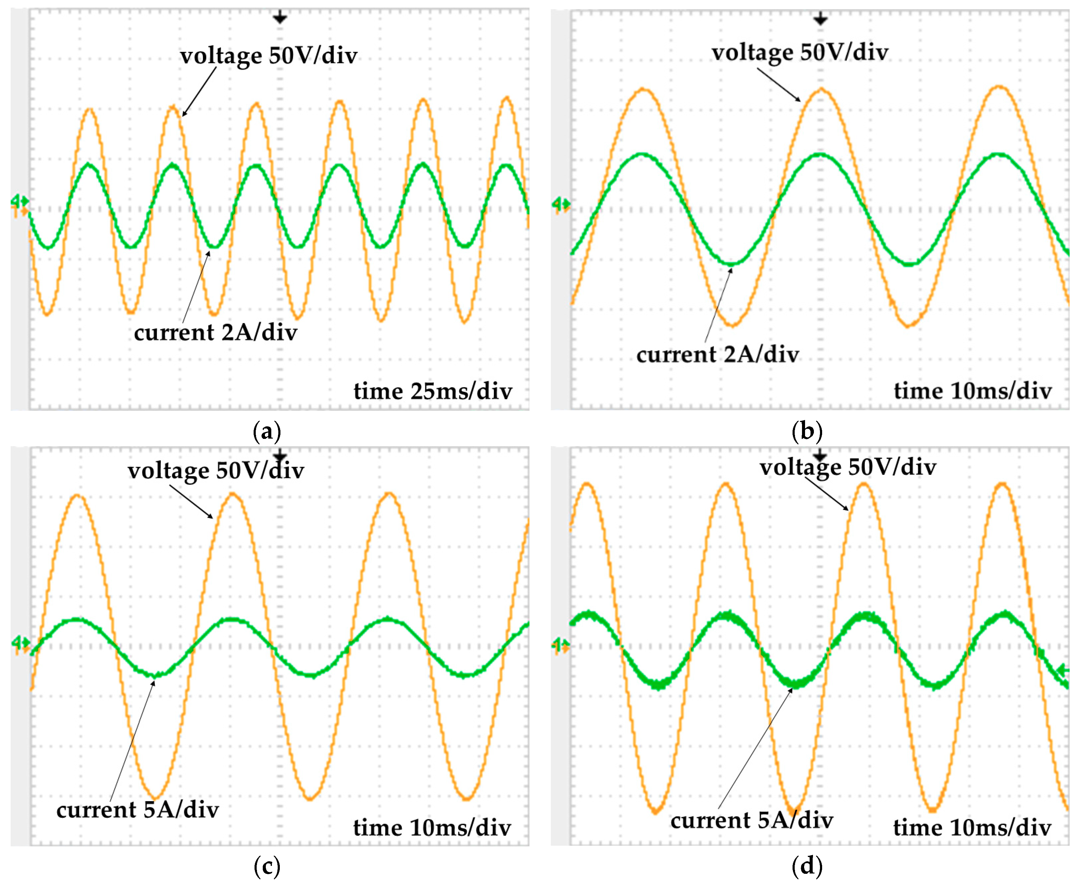
It was possible to check the proper operation of the SEPIC-type rectifier in a wide range of wind speed with a high power factor and low harmonic content, presenting the output voltage according to the designed value. Figure 14 presents results of input voltage and current for equivalent frequencies of f = 24 Hz (vwind = 7.2 m/s), f = 28 Hz (vwind = 8.4 m/s), f = 32 Hz (vwind = 9.6 m/s), and f = 36 Hz (vwind = 10.8 m/s). An almost perfect sinusoidal input current, following input voltage is obtained only by applying an appropriate duty cycle, corroborating that an unity power factor is achieved.

5. Conclusions

It has been shown that a three-phase SEPIC-type DCM rectifier can be implemented using three active switches controlled by the same gate drive signal. The choice of three switches allows fewer semiconductor devices in the current path during switches turned-on. Equal found in a single-phase SEPIC converter, this one presents an input inductor, an intermedium capacitor, and a second inductor in each phase. With an appropriate element design and DCM operation, as pointed out in the text, the input current will be in phase to the input voltage, resulting in a high-power-factor rectifier.
The simulation (Figure 6) as well experimental results (Figure 11 and Figure 14) validated that the proposed topology naturally presents the input currents in the AC source as an image of the generated voltage, without any control of the current at the converter input. It was possible to achieve a reduced harmonic content, which is a better solution than the equivalent low-power boost topology found in the literature (which provides extremely deformed currents in relation to the voltage). It is relevant to observe that no input filter is required to achieve high-quality input currents in this proposed converter. Again, the SEPIC-type converter is attested to verify that the capacitor voltage is equal to the input voltage along with the line period.
Even though no control loop was performed in the presented results, the output voltage/duty cycle transfer function was presented. It is useful for a control loop to control the output voltage. As the converter operated in the discontinuous conduction mode, the output voltage to duty cycle ratio varied with load variation. The DCM operation ensures the input current waveform without making use of a current loop. The simulation results for small step changes in the duty cycle, shown in Figure 9, validated the developed TF representative of the dynamic converter behavior and adequate as an effective control loop design.
In relation to the generated power, a significant improvement is obtained. Having low THD of the current implies reduced low-frequency oscillations. The output voltage and average output current obtained by the simulation as well as experimentally were continuous, with negligible oscillations, leading to a constant power delivered to the load.
The experimental results were satisfactory for the equivalent wind speed conditions at a nominal value of 12 m/s and for reduced values, keeping a high power factor and reduced harmonic current content, validating the proposal of the SEPIC-type converter to be employed in grid AC–DC conversion as well as PMSG or microturbines for high-power-factor rectification.
It is meaningful that the electric power absorbed from the line or generator is almost constant, only presenting a high-frequency ripple. For a low-power PMSG, it is relevant.
The results obtained have proved the efficacy of the converter for the presented purpose. However, some important points must be considered: the active switches must be able to withstand a maximum voltage equal to the peak line voltage plus the rectified output voltage. This can increase switching losses, especially when the topology is operating as an elevator.
Coupling capacitors, as in a conventional SEPIC converter, are subjected to currents with considerable RMS values. Thus, the use of capacitors that support a high current and have low internal resistance is highly recommended. Although the losses have not been evaluated, the use of semiconductor components (IGBT/MOSFET/diodes) of the Sic or Gan type will certainly contribute to their decrease, making the topology even more competitive.

Author Contributions

Conceptualization, T.F. and D.S.; formal analysis, T.F., D.S., and J.C.; funding acquisition, D.S.; methodology, project administration, software, supervision, validation, writing—original draft preparation, T.F. and D.S.; writing—review and editing, W.d.S. and P.M. All authors have read and agreed to the published version of the manuscript.

Funding

This work was partially supported by FAPES/CNPq with PRONEX and by the Coordenação de Aperfeiçoamento de Pessoal de Nível Superior—Brasil (CAPES)—Finance Code 001″.

Conflicts of Interest

The authors declare no conflict of interest.

References

  1. Ghareeb, A.T.; Mohamed, A.A.; Mohammed, O.A. DC microgrids and distribution systems: An overview. In Proceedings of the IEEE Power and Energy Society General Meeting, Vancouver, BC, Canada, 21–25 July 2013. [Google Scholar]
  2. Han, Y.; Ning, X.; Yang, P.; Xu, L. Review of Power Sharing, Voltage Restoration and Stabilization Techniques in Hierarchical Controlled DC Microgrids. IEEE Access 2019, 7, 149202–149223. [Google Scholar] [CrossRef]
  3. Mackay, L.; van der Blij, N.H.; Ramirez-Elizondo, L.; Bauer, P. Toward the Universal DC Distribution System. Electr. Power Compon. Syst. 2017, 45, 1032–1042. [Google Scholar] [CrossRef] [Green Version]
  4. Noroozian, R.; Abedi, M.; Gharehpetian, G.B.; Hosseini, S.H. Distributed resources and DC distribution system combination for high power quality. Int. J. Electr. Power Energy Syst. 2010, 32, 769–781. [Google Scholar] [CrossRef]
  5. Patrao, I.; Figueres, E.; Garcerá, G.; González-Medina, R. Microgrid architectures for low voltage distributed generation. Renew. Sustain. Energy Rev. 2015, 43, 415–424. [Google Scholar] [CrossRef]
  6. Lee, J.-Y.; Heo, K.-W.; Kim, K.-T.; Jung, J.-H. Analysis and Design of Three-Phase Buck Rectifier Employing UPS to Supply High Reliable DC Power. Energies 2020, 13, 1704. [Google Scholar] [CrossRef] [Green Version]
  7. Yao, K.; Meng, Q.; Bo, Y.; Hu, W. Three-Phase Single-Switch DCM Boost PFC Converter with Optimum Utilization Control of Switching Cycles. IEEE Trans. Ind. Electron. 2016, 63, 60–70. [Google Scholar] [CrossRef]
  8. Foroozeshfar, R.; Adib, E. Three-phase ripple free DCM boost converter with low THD. IET Power Electron. 2019, 12, 120–128. [Google Scholar] [CrossRef]
  9. Granza, M.H.; Gules, R.; Font, C.H.I. Hybrid and Three-Level Three-Phase Rectifiers Using Interleaved DCM Boost Converters. IEEE Access 2019, 7, 160168–160176. [Google Scholar] [CrossRef]
  10. Yao, K.; Meng, Q.; Yang, F.; Yang, S. A Novel Control Scheme of Three-Phase Single-Switch Quasi-CRM Boost Rectifier. IEEE Trans. Power Electron. 2017, 32, 6236–6244. [Google Scholar] [CrossRef]
  11. Azazi, H.Z.; Ahmed, S.M.; Lashine, A.E. Single-stage three-phase boost power factor correction circuit for AC–DC converter. Int. J. Electron. 2018, 105, 30–41. [Google Scholar] [CrossRef]
  12. Liu, J.; Xu, W.; Chan, K.W.; Liu, M.; Zhang, X.; Chan, N.H.L. A Three-Phase Single-Stage AC-DC Wireless-Power-Transfer Converter with Power Factor Correction and Bus Voltage Control. IEEE J. Emerg. Sel. Top. Power Electron. 2020, 8, 1782–1800. [Google Scholar] [CrossRef]
  13. Foroozeshfar, R.; Adib, E. Unity power factor three-phase AC-DC converter applying two switch DCM SEPIC converter with coupled inductors. IET Power Electron. 2018, 11, 945–951. [Google Scholar] [CrossRef]
  14. Gangavarapu, S.; Rathore Gae, A.K. A Three-Phase Single-Stage Isolated Flyback-Based PFC Converter with Leakage Energy Recovery Clamping Circuit. IEEE Trans. Transp. Electrif. 2019, 5, 1155–1168. [Google Scholar] [CrossRef]
  15. Gangavarapu, S.; Rathore, A.K.; Fulwani, D.M. Three-Phase Single-Stage-Isolated Cuk-Based PFC Converter. IEEE Trans. Power Electron. 2019, 34, 1798–1808. [Google Scholar] [CrossRef]
  16. Metwaly, M.K.; Azazi, H.Z.; Deraz, S.A.; Dessouki, M.E.; Zaky, M.S. Power Factor Correction of Three-Phase PWM AC Chopper Fed Induction Motor Drive System Using HBCC Technique. IEEE Access 2019, 7, 43438–43452. [Google Scholar] [CrossRef]
  17. Lan, D.; Das, P.; Ye, C.; Sahoo, S.K.; Srinivasan, D. High Frequency Link Matrix Rectifier in Discontinuous Conduction Mode with Reduced Input Current Distortion. IEEE Trans. Ind. Electron. 2020. [Google Scholar] [CrossRef]
  18. Miniböck, J.; Mauerer, M.; Huber, J.E.; Kolar, J.W. Three-phase buck–boost PFC rectifier with common-mode free output voltage and low semiconductor blocking voltage stress. IET Power Electron. 2019, 12, 2022–2030. [Google Scholar] [CrossRef] [Green Version]
  19. Zhang, Q.; Na, T.; Song, L.; Dong, S. A Novel Modulation for Soft-Switching Three-Phase Quasi-Z-Source Rectifier without Auxiliary Circuit. IEEE Trans. Ind. Electron. 2018, 65, 5157–5166. [Google Scholar] [CrossRef]
  20. Aiello, G.; Cacciato, M.; Scarcella, G.; Scelba, G.; Gennaro, F.; Aiello, N. Real-time emulation of a three-phase Vienna rectifier with DC voltage control and power factor correction. Electr. Eng. 2020, 102, 97–106. [Google Scholar] [CrossRef]
  21. Prakash, P.S.; Kalpana, R.; Singh, B. Third Harmonic Current Injection Based Front-End AC-DC Converter for Power Quality Improvement in DC Distribution Systems. In Proceedings of the 2020 IEEE International Conference on Power Electronics, Smart Grid and Renewable Energy (PESGRE2020), Cochin, India, 2–4 January 2020; pp. 1–6. [Google Scholar]
  22. Abdelsalam, I.; Alajmi, B.N.; Marei, M.I.; Alhajri, M.F. Wind energy conversion system based on open-end winding three-phase PMSG coupled with ac−dc buck-boost converter. J. Eng. 2019, 2019, 4336–4340. [Google Scholar] [CrossRef]
  23. Chub, A.; Husev, O.; Blinov, A.; Vinnikov, D. Novel Isolated Power Conditioning Unit for Micro Wind Turbine Applications. IEEE Trans. Ind. Electron. 2017, 64, 5984–5993. [Google Scholar] [CrossRef]
  24. Chen, Z.; Guerrero, J.M.; Blaabjerg, F. A review of the state of the art of power electronics for wind turbines. IEEE Trans. Power Electron. 2009, 24, 1859–1875. [Google Scholar] [CrossRef]
  25. Tofoli, F.L.; de Oliveira, D.S.; Barreto, L.H.S.C.; Oliveira, E.F.; Praça, P.P.; Antunes, F.M. Low cost wind energy conversion system based on the discontinuous conduction mode three-phase semi-controlled rectifier. IET Power Electron. 2015, 8, 851–859. [Google Scholar] [CrossRef] [Green Version]
  26. Jenisha, C.M.; Ammasaigounden, N.; Kumaresan, N.; BhagyaSri, K. Power electronic interface with de-coupled control for wind-driven PMSG feeding utility grid and DC load. IET Power Electron. 2018, 11, 329–338. [Google Scholar] [CrossRef]
  27. Rahimi, M. Modeling, control and stability analysis of grid connected PMSG based wind turbine assisted with diode rectifier and boost converter. Int. J. Electr. Power Energy Syst. 2017, 93, 84–96. [Google Scholar] [CrossRef]
  28. Aubrée, R.; Auger, F.; Macé, M.; Loron, L. Design of an efficient small wind-energy conversion system with an adaptive sensorless MPPT strategy. Renew. Energy 2016, 86, 280–291. [Google Scholar] [CrossRef]
  29. Zhang, S.; Tseng, K.-J.; Vilathgamuwa, D.M.; Nguyen, T.D.; Wang, X.-Y. Design of a Robust Grid Interface System for PMSG-Based Wind Turbine Generators. IEEE Trans. Ind. Electron. 2011, 58, 316–328. [Google Scholar] [CrossRef]
  30. Yaramasu, V.; Dekka, A.; Durán, M.J.; Kouro, S.; Wu, B. PMSG-based wind energy conversion systems: Survey on power converters and controls. IET Electr. Power Appl. 2017, 11, 956–968. [Google Scholar] [CrossRef]
  31. Carranza, O.; Figueres, E.; Garcerá, G.; González, L.G. A Control Circuit Small Wind Turbines with Low Harmonic Distortion and Improved Power Factor. In Proceedings of the International Conference on Renewable Energies and Power Quality (ICREPQ’09), Valencia, Spain, 15–17 April 2009; pp. 447–452. [Google Scholar]
  32. Tonkoski, R.; Lopes, L.A.C.; Dos Reis, F. A single-switch three-phase boost rectifier to reduce the generator losses in wind energy conversion systems. In Proceedings of the 2009 IEEE Electrical Power & Energy Conference (EPEC), Montreal, QC, Canada, 22–23 October 2009; pp. 1–8. [Google Scholar]
  33. Dos Reis, F.S.; Tan, K.; Islam, S. Using PFC for harmonic mitigation in wind turbine energy conversion systems. In Proceedings of the IECON Proceedings (Industrial Electronics Conference), Busan, Korea, 2–6 November 2004; Volume 3, pp. 3100–3105. [Google Scholar]
  34. Singer, S. Realization of Loss-Free Resistive Elements. IEEE Trans. Circuits Syst. 1990, 37, 54–60. [Google Scholar] [CrossRef]
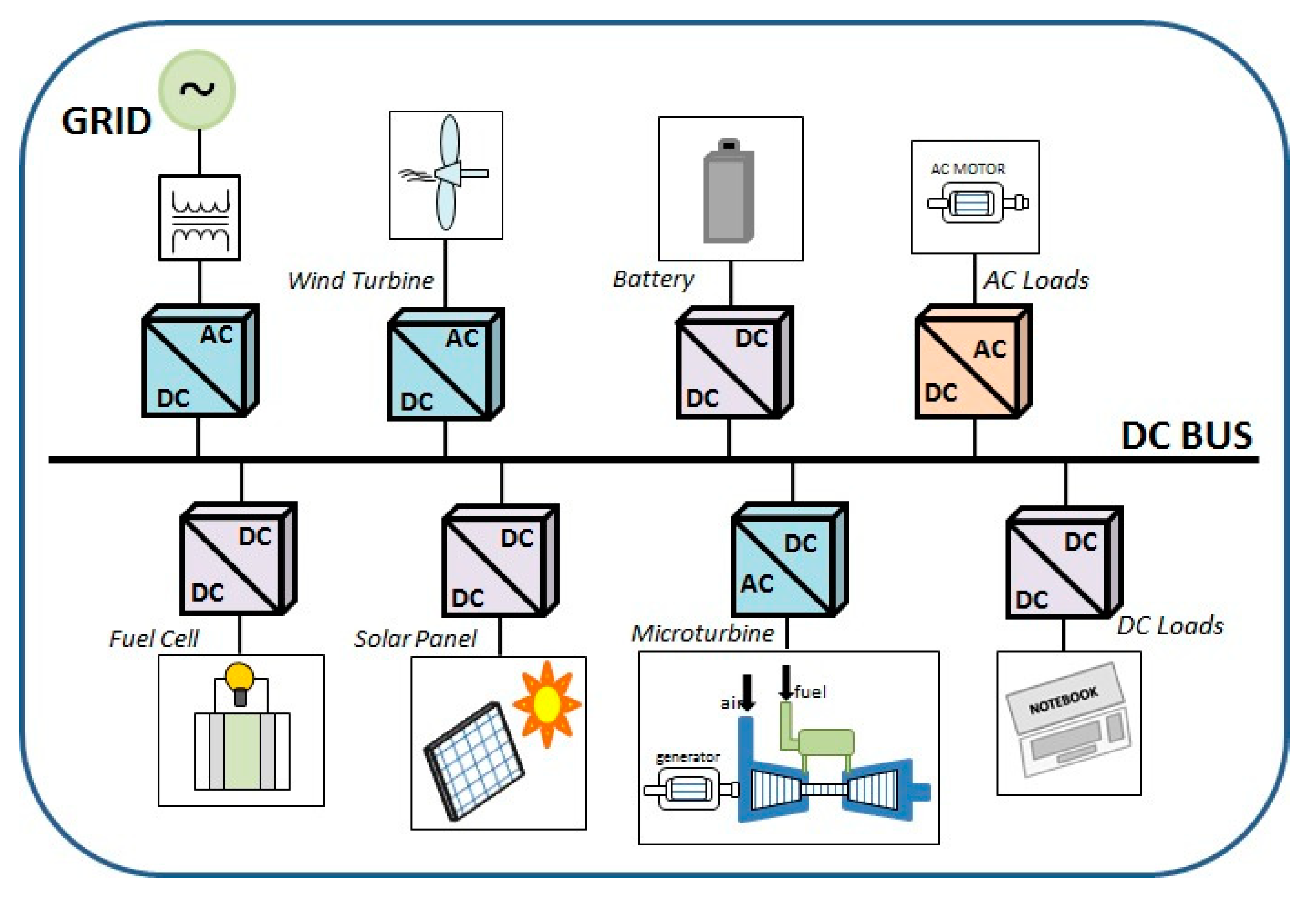
Figure 1. Typical configuration of a DC microgrid.
Energies 14 00256 g001
Figure 2. Single-switch three-phase discontinuous conduction mode (DCM) boost converter: (a) typical input voltage and filtered current; (b) electric power absorbed from the source.
Energies 14 00256 g002
Figure 3. The proposed three-phase rectifier topology.
Energies 14 00256 g003
Figure 4. 3ϕ SEPIC-type equivalent circuit during stages: (a) first stage (ton); (b) second stage (tdon1); (c) third stage (tdon2); (d) fourth stage (freewheeling).
Energies 14 00256 g004
Figure 5. Input currents on L1 in a few switching periods.
Energies 14 00256 g005
Figure 6. Output voltage Vo, input voltage (v1), and current (i1).
Energies 14 00256 g006
Figure 7. Phase voltage (v1) and the respective capacitor voltage (vC1).
Energies 14 00256 g007
Figure 8. Electric power absorbed by the converter from AC source.
Energies 14 00256 g008
Figure 9. Simulated output voltage (Vo) and estimated output voltage ( V ^ ): (a) duty cycle increased by 10% at rated power; (b) duty cycle decreased by 10% at 50% of rated power.
Energies 14 00256 g009
Figure 10. SEPIC-type 1 kW workbench.
Energies 14 00256 g010
Figure 11. Experimental input voltage and current: (a) 40 Hz (vwind = 12 m/s); (b) 20 Hz (vwind = 6 m/s).
Energies 14 00256 g011
Figure 12. Operational point of f = 40 Hz: (a) L2 current (2 A/div), L2 current (5 A/div) and (b) L2 current (5 A/div).
Energies 14 00256 g012
Figure 13. Operation at f = 40 Hz (vwind = 12 m/s): (a) output voltage; (b) load current.
Energies 14 00256 g013
Figure 14. Experimental input voltage and current: (a) f = 24 Hz (vwind = 7.2 m/s); (b) f = 28 Hz (vwind = 8.4 m/s); (c) f = 32 Hz (vwind = 9.6 m/s); (d) f = 36 Hz (vwind = 10.8 m/s).
Energies 14 00256 g014
Table 1. System specification.
Ve (V)P (kW)Vo(V)
2201400
Table 2. Project of a 1 kW 3ϕ SEPIC-type rectifier.
fs (kHz)d 40 Hz(%)d 20 Hz(%)L1 (mH)L2 (µH)C1 (µF)C0 (µF)
20282012954.7100
Table 3. Commercial components used on the workbench.
IGBTDiodeCapacitor 4.7 µFL1 (12 mH)L2 (95 µH)Capacitor C0 (100 µF)
HGTG11N120CND (FAIRCHILD)HFA50PA60C (International Rectifier)940C12P47K-F (Cornell Dubilier)Made of silicon steelBuilt with ferrite core450 V Eletrolytic (Epcos)
Table 4. SEPIC summary operation: experimental results.
Wind SpeedPower FactorCurrent TDH
12 m/s0.9985.7%
6 m/s0.9934.8%
Publisher’s Note: MDPI stays neutral with regard to jurisdictional claims in published maps and institutional affiliations.