Article

Numerical Investigation on a Axial Slot Casing Treatment of a Large Circumferential Interval and Small Opening Area

College of Energy and Power Engineering, Nanjing University of Aeronautics and Astronautics, Nanjing 210016, China
*
Author to whom correspondence should be addressed.
Energies 2021, 14(19), 6181; https://doi.org/10.3390/en14196181
Submission received: 22 July 2021 / Revised: 31 August 2021 / Accepted: 15 September 2021 / Published: 28 September 2021
(This article belongs to the Special Issue Advances in Gas Turbine Performance, Heat Transfer and Aerodynamics)

Abstract

:
Axial slot casing treatment is a common method to extend the stall margin of a compressor. Based on the mechanism of unsteady flow control, this paper redesigns axial slots with large circumferential interval and small opening area. To test the effect of this axial slot structure, unsteady numerical simulations were carried out with different slot areas and circumferential intervals. The results show that this novel axial slot casing treatment can significantly improve compressor stall margin. Meanwhile, compared with the traditional axial slot, the efficiency loss is greatly reduced. The flow field analysis shows that the new axial slot structure proposed in this paper can suppress the development of tip leakage vortex and unsteadiness in the tip region at the near stall condition through decreasing the tip loading periodically. Moreover, we find that the slot area is proportional to the improvement of stability margin. Under the same slot area, an excessive number of slots is not conducive to the improvement of the stability margin.

1. Introduction

As the loading of the compressor/fan increases, the stability problem becomes more and more prominent, which seriously restricts the development of high-performance aeroengines [1]. Therefore, some flow control methods are needed to enhance the stability margin of the compressor to meet the requirements of high-performance engines [2].
Since most instability phenomena firstly occur at the tip of the blade, some casing treatment structures can improve the stability margin effectively through influencing the tip flow field. Among those casing treatment methods, axial slot structures are widely used because of their remarkable effect of extending the stall margin of the compressor. Many researchers have explored the stability enhancement mechanism and structure optimization of axial slots. Wilke and Kau [3] conducted numerical simulations on a transonic compressor for a mechanism that improved the stall margin by using axial slots. The results revealed that axial slots use the pressure difference between the upstream and downstream to enhance the momentum exchange and suppress the tip leakage vortex to improve the flow field. Smith and Cumpsty [4] conducted an experiment to measure the flow field in the slots and blade tip. They demonstrated that the axial slots suck the relatively low momentum fluid downstream and inject the high momentum fluid into the upstream to suppress the development of tip leakage flow, and they pointed out that this might be the main reason why the stall margin is improved. From the perspective of flow control, these researches all deem the axial slots as a steady method which is inclined to promote the momentum exchange between low momentum flow and high momentum flow to delay separation. Therefore, in order to enhance the momentum exchange intensity, the traditional axial slot casing treatment tends to use a large opening area and intensive slots, and the optimization of the slot structure is devoted to guaranteeing that the channel of momentum exchange is smooth [5,6]. However, large-scale momentum exchange also brings obvious efficiency loss and total pressure ratio loss. For example, according to the experiment conducted by Moore [7], the stability margin extension effect and efficiency loss are inversely related. They measured the parameters at the inlet and outlet of compressor and found that, when axial slots improve stall margin by 15.8%, they also bring about 6% efficiency loss.
In fact, due to the relative motion between static axial slots and the rotating blades, the effect of axial slots is indeed the unsteady excitation on the tip flow field of the compressor. The research showed that the unsteady flow method can delay the flow separation with less momentum exchange compared with a steady flow control method through the unsteady coupling effect between separated flow and excitation [8,9]. Some researchers have already proposed the novel casing treatment structure based on this mechanism. Dakun Sun and Xiaofeng Sun [10,11] proposed a novel casing treatment to realize the stall margin enhancement by suppressing the stall precursor. The open area ratio of this casing treatment is only 4–12%, much less than the traditional casing treatment of over 50%. It proves that the stall margin can be extended with a small momentum exchange. The mechanism of this casing treatment relies on the unsteady interaction between the shedding vortex and stall cells in the tip region, which can suppress the nonlinear amplification of the stall precursor. In this paper, we redesigned the traditional axial slot casing treatment based on the unsteady excitation mechanism. The opening area and number of slots proposed in this paper obviously decreases compared with traditional axial slots casing treatment structure. For unsteady excitation of axial slots casing treatment, the opening area ratio influence the excitation intensity and the number of slots influences excitation frequency. In addition, this paper conducted unsteady numerical simulations to study the influence of excitation frequency and excitation intensity on compressor performances.

2. Numerical Simulation Methods and Validation
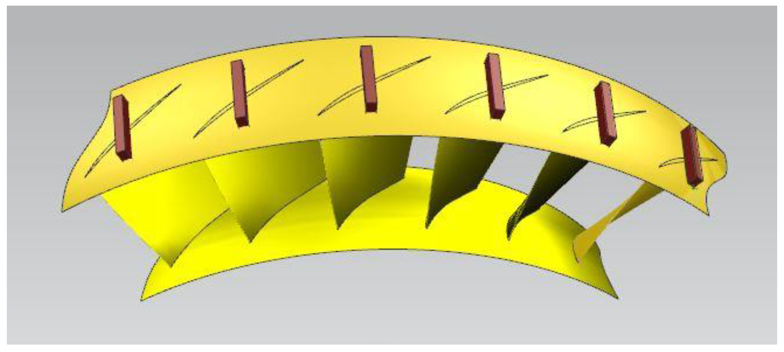
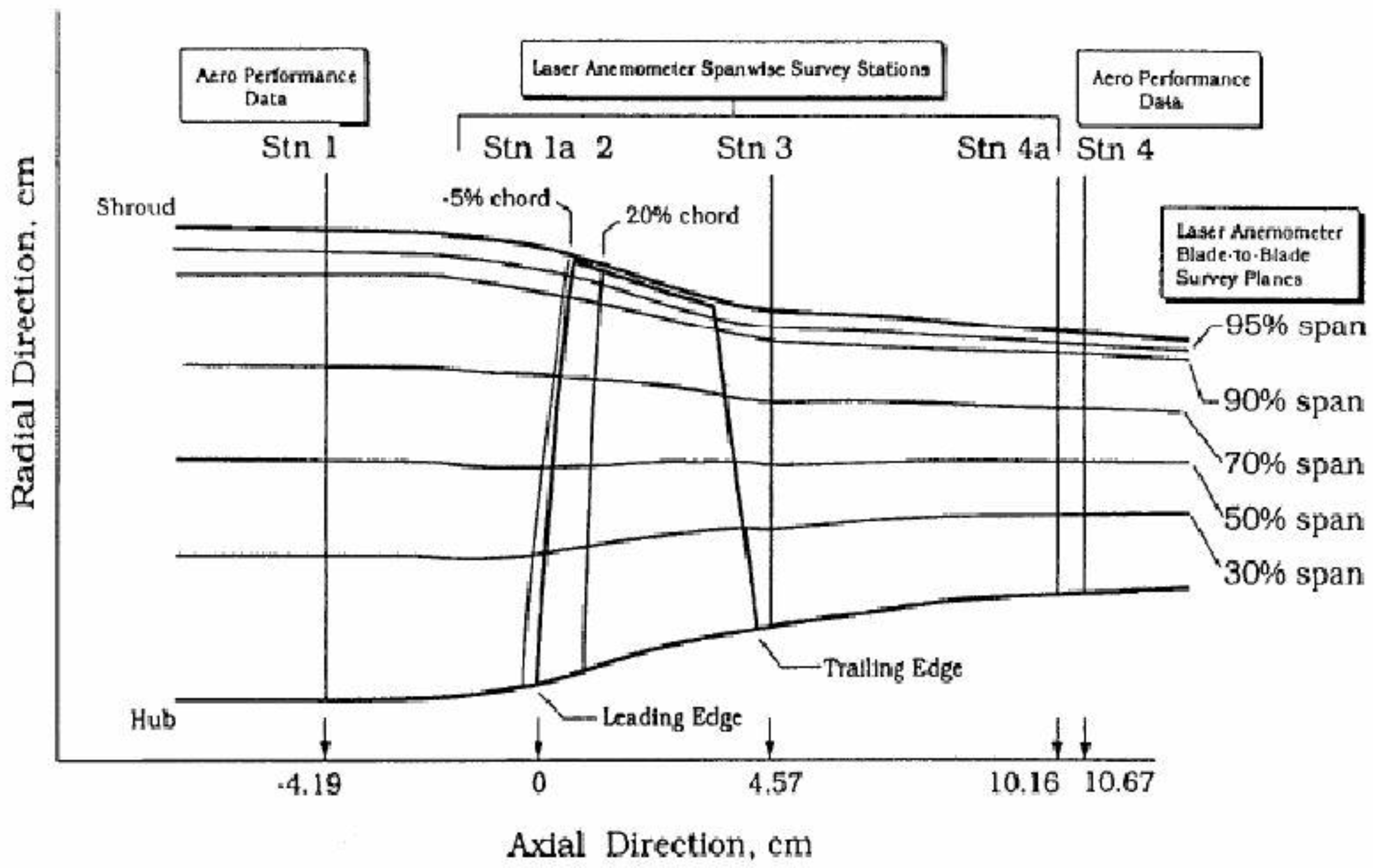
2.1. Test Model

Rotor 37 is selected as the test rotor in this paper because there is a detailed measurement report available to check the reliability of numerical simulations [12]. Experimental measurement positions are shown in Figure 1. The probes are fixed at positions 1 and 4, which measure total pressure, total temperature and flow angle at inlet and outlet. The detailed flow field between positions 2 and position 3 is measured by LDV. Table 1 shows some basic geometric and aerodynamic parameters. In 1994, ASME published its results as a basis for evaluating the reliability and accuracy of CFD programs.
In order to study the influence of excitation frequency and excitation intensity on compressor performance and explore the mechanism for stall margin improvement, we designed a variety of axial slot structures, shown in Table 2. Slot area rate ε is defined as the ratio of contacting area between slots and casing in the same axial range. All axial slots have the same depth and axial range. The depth is 10% of the axial chord length of the tip, and the axial range is from leading edge to tailing edge. Figure 2 depicts the novel axial slots of 10% area rate and a large circumferential interval.

2.2. Simulation Methods

Numerical simulations were performed on commercial software CFX. The SST model was used in this simulation. We used a high-resolution scheme to solve N-S equations in the steady simulation, and a second order backward scheme was used in the unsteady simulation. The multi-reference system model was adopted. The rotor model was in a rotating reference coordinate system, and the slots model connected with a thin layer was in a stationary coordinate system. The thin layer here was used to conveniently set the interface between the rotating model and stationary model. The thickness of the thin layer accounted for about 1/10 of the blade tip gap. In the steady calculation, the frozen rotor method was used to transfer the data between the rotating and stationary model, and the unsteady calculation used the sliding mesh method to continuously change the relative position of rotor and axial slots to transfer data. The physical time step for the unsteady simulation was set as 2.5 × 10 6 s, which ensured 40 steps in a blade passing period. Additionally, inner time steps in a physical time step were 20. In order to speed up the convergence speed of the unsteady calculation, we used the result of steady calculation as the initial field of unsteady calculation. The computational grid is shown in Figure 3. Single passage is simulated in this paper. To ensure mesh orthogonality, O-type grids were used around the blades, and the number of nodes around the blades in a layer as 271. The upstream and downstream domains used H-type grids, with 57 nodes in the circumferential direction and 73 nodes in the radial direction. The grid in tip clearance was separately meshed using O-shaped grids; the number of radial nodes was 17. The number of grids for the entire blade channel was 760,000. The axial slots used an H-type grid structure, containing 57 grid points in the axial direction and 17 grid points in the radial direction. The number of circumferential grid points depends on the slots area. The grid height of the first layer was 0.003 mm to ensure Y+ < 1. In order to verify the grid independence, we also increased the grid number to 1.23 million and 1.76 million without changing the grid topology. The specific comparison results are described below.
Total temperature 288 K, total pressure Pa and flow angle of axial direction are given at the inlet boundary condition. Static pressure with radial equilibrium was set at outlet. No-slip and adiabatic conditions were imposed on solid walls. Periodic boundary conditions are given at both sides of the channel. In the calculation process, we obtained the entire characteristic curve of the compressor through increasing the outlet pressure gradually and took the last operating condition before the stall as the near-stall point. Each point on the compressor characteristic curves is the average value of the unsteady calculation results. When the monitored quantity presented regular periodic changes in the unsteady calculation process and the RMS residual value was below 1 × 10 6 s, we considered the calculation to be convergent.

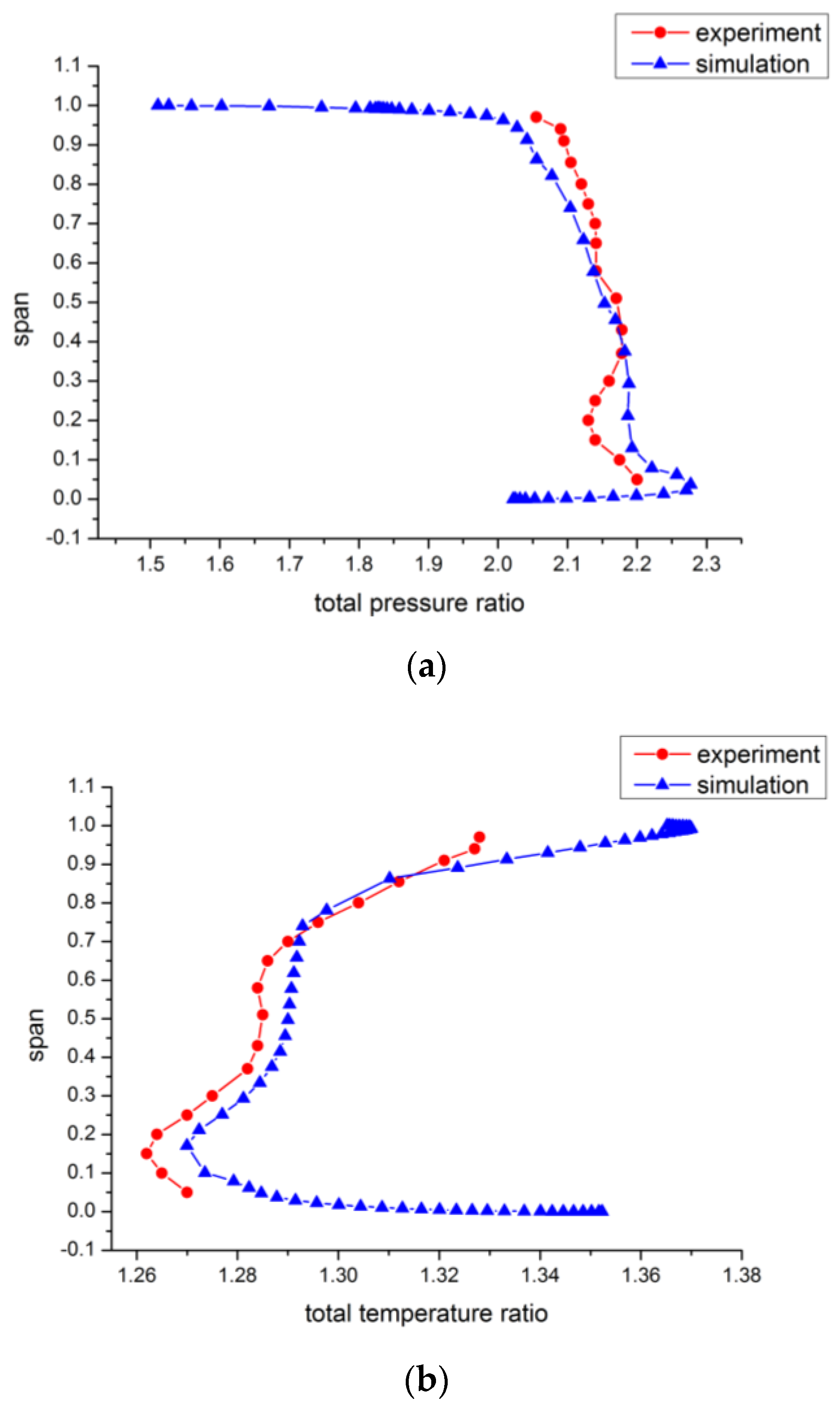
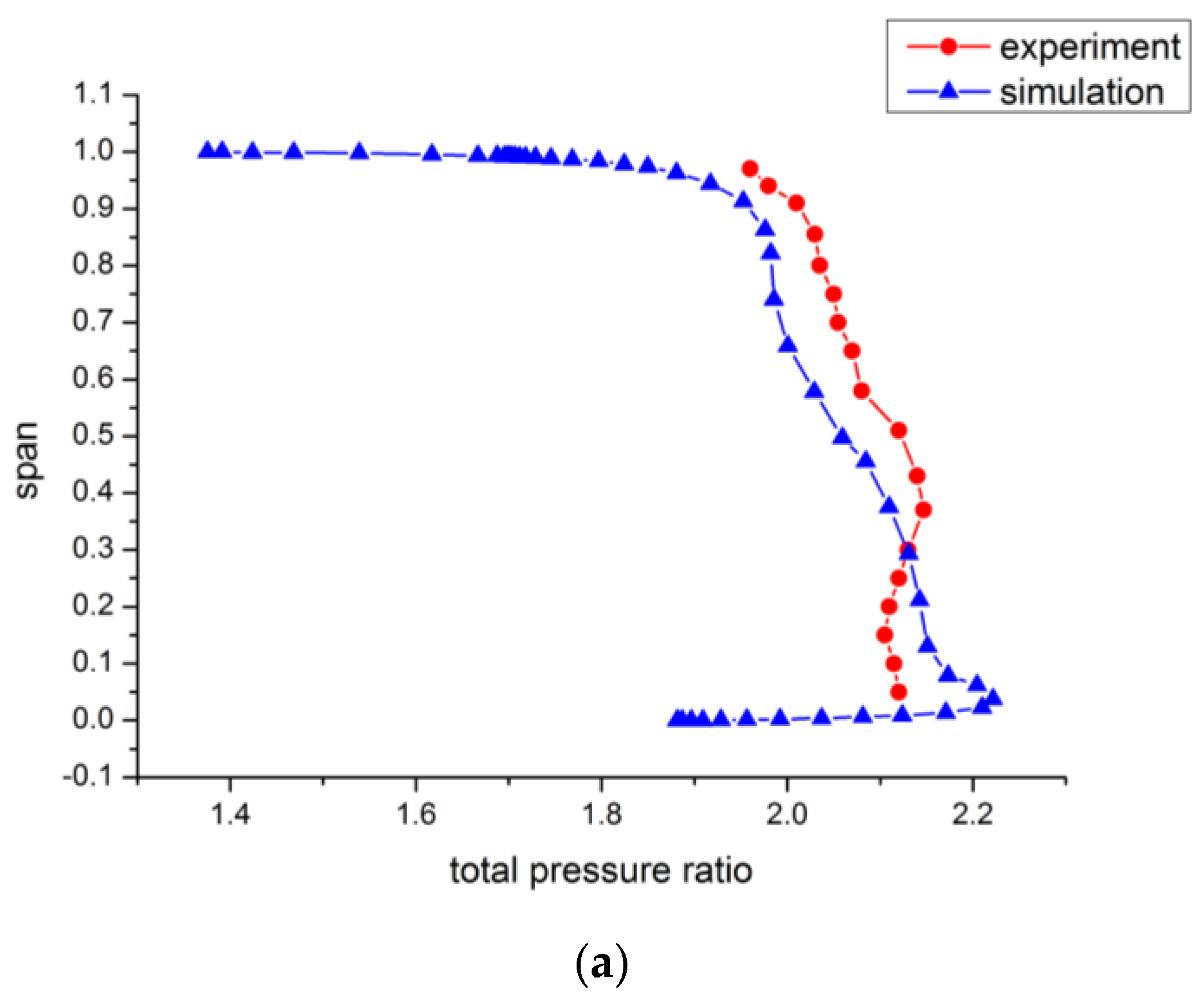
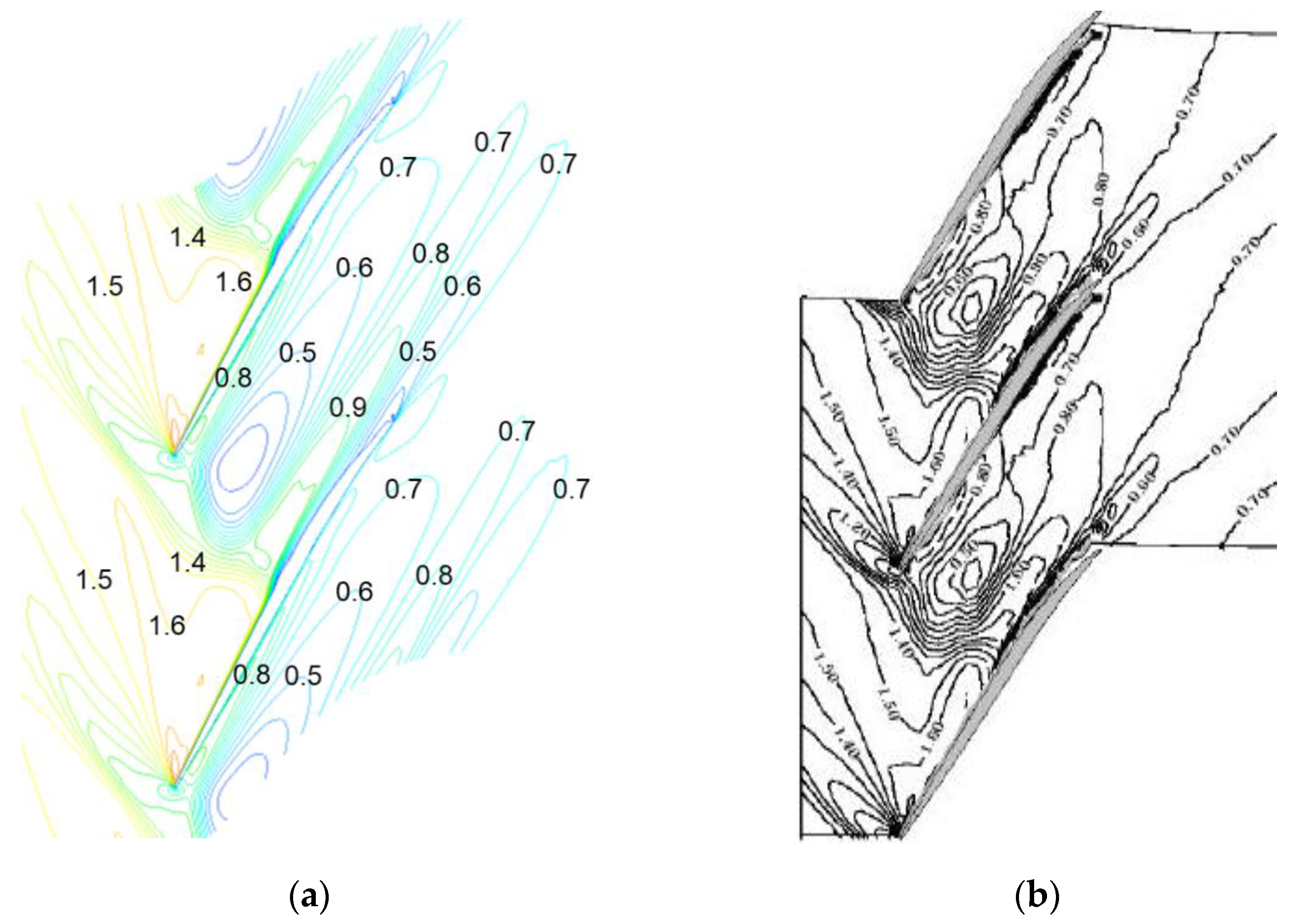
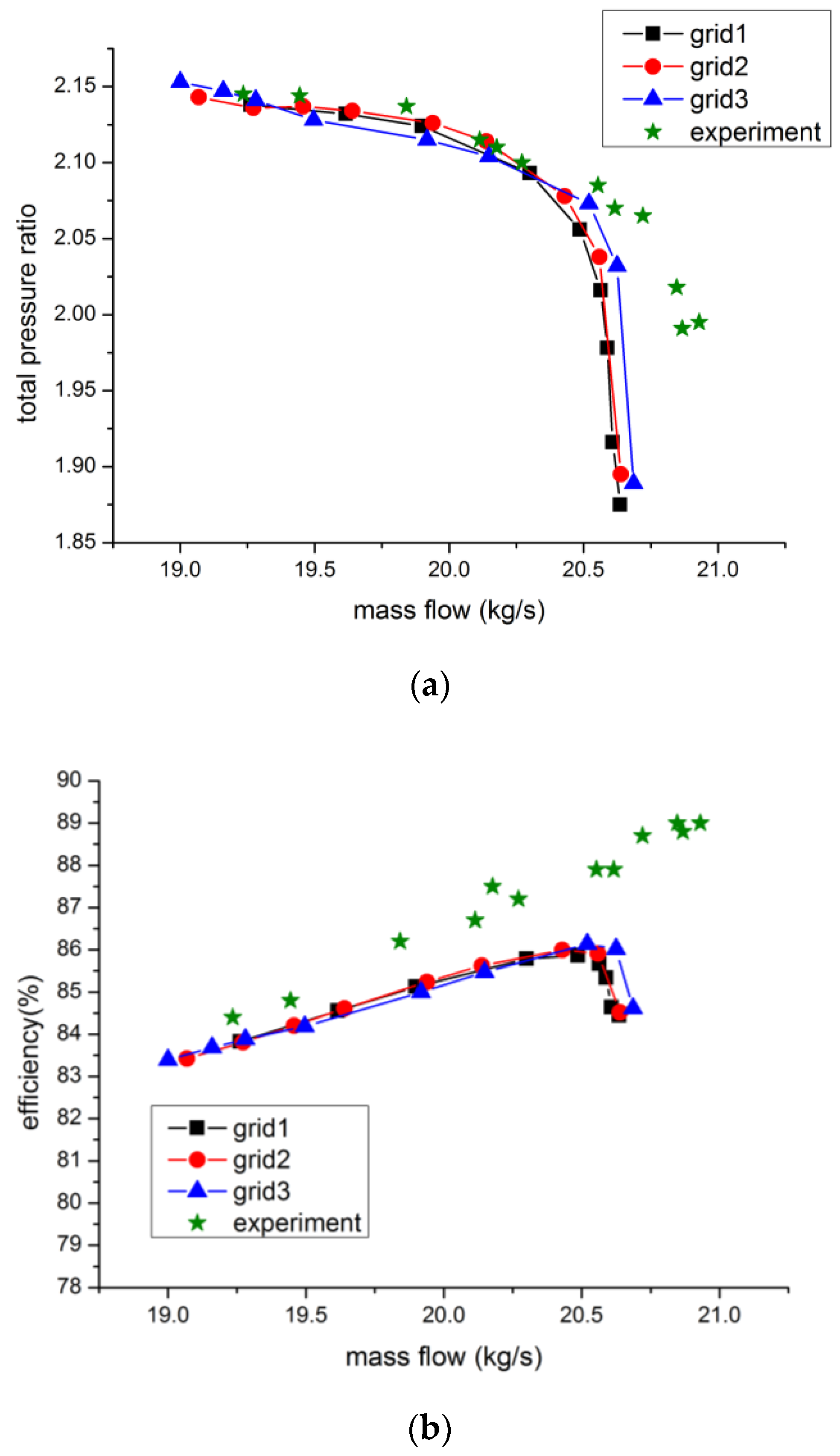
2.3. Validation of Simulation Results

Figure 4a,b depicts the comparison between the experimental results and numerical results of different grids. Among them, grid 1, grid 2 and grid 3, respectively, correspond to 0.76 million, 1.23 million and 1.76 million node points. For grid 1, the discrepancy between mass flow near the stall point predicted by the numerical simulation and the experimental result is about 0.4%, and the mass flow near the blocking point is about 1.5%. The results of grid 1 and grid 2 show little difference, except that the near stall mass flow predicted by grid 2 is less than that predicted by grid 1 by 1.03%. However, the mass flow near the stall point in the grid 1 case is closer to the experimental results. For grid 3, the discrepancy at the mass flow near the stall point is 0.8%, and the mass flow near the chocking point is about 1.2%. All simulation results obviously underestimate the efficiency value compared with experiment results, which is related with underestimation of efficiency in experiments and can also be found in other researchers’ simulation results [13]. However, all the numerical results follow the same trend as the experiment results except the points near the chocking point, and the difference between grids of different density is small. The discrepancy near the chocking point is not the main concern because the target in this paper is to study the stall margin. Therefore, we chose the grid 1 (0.76 million) for the sake of decreasing the calculation time of the unsteady simulation.
Figure 5a,b shows the span distribution of the total pressure ratio and total temperature ratio at the near stall point, and Figure 6a,b shows the span distribution at the peak efficiency point. At the near stall point, the numerical results overestimate the total pressure ratio in the hub region and underestimate the total pressure ratio in the tip region. The total temperature ratio is underestimated by the numerical simulation along the whole span at the near stall point. At the peak efficiency point, the discrepancy between the numerical and experimental results is obvious. It is also reflected in the characteristic curves, which underestimate the peak efficiency by 3%. Overall, we can find that the radial distribution of the total pressure ratio and total temperature ratio obtained by the numerical results is consistent with the experimental results trend.
The flow field at the near stall point is essential to this research, so the relative Mach number distribution of the 95% B2B surface at the near stall point is compared in Figure 7. The location of shock wave and the low Mach number region are predicted well by the CFD simulation. Therefore, we can assume that the numerical simulation method used in this paper can predict the characteristic curve and flow field details of the compressor accurately.

3. Results and Discussions

In order to improve the flow field and the stability margin effectively, traditional axial slot casing treatments often use a large number of slots and then a very large slot area slot to achieve a large amount of momentum exchange between high-energy fluid and low-energy fluid. Therefore, the stability margin improvement is accompanied by a non-negligible efficiency loss. Based on the relative movement between the stationary axial slots and rotating blades, the excitation of the axial slots on the blade tip flow field is essentially a periodic excitation. Looking at the design of the axial slot casing treatment structure from the perspective of periodic excitation, the slots area represents the excitation intensity, and the circumferential interval between slots affects the excitation frequency. Therefore, this article focuses on the influence of the slot area and the circumferential interval between the slots on the stall margin, so that the new type of axial slot proposed in this article can be applied more effectively.

3.1. The Influence of Axial Slots Area

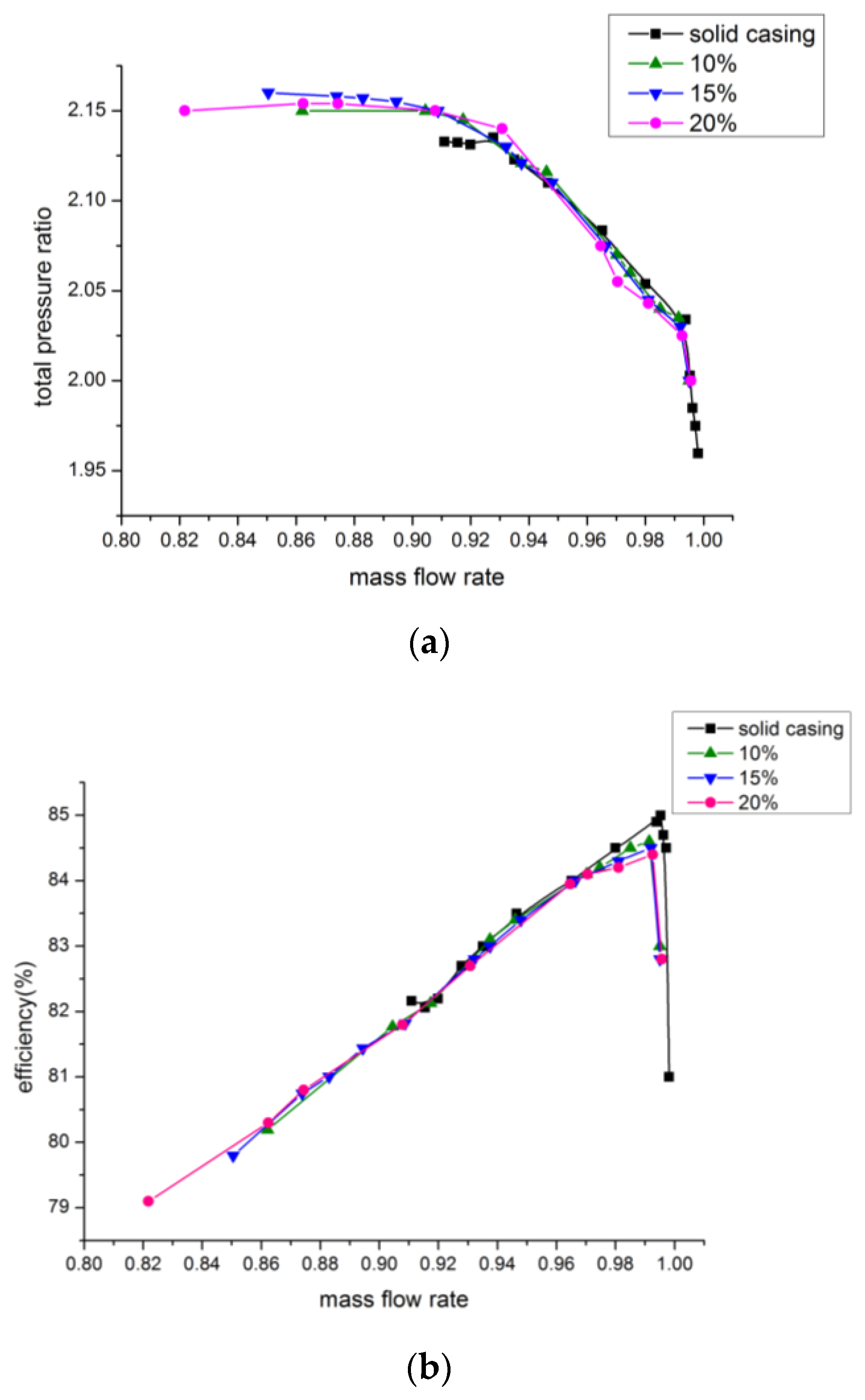
3.1.1. The Influence on Compressor Characteristic Curve

Figure 8 displays total pressure ratio and efficiency curves of the compressor of the solid casing and axial slots of different areas. It can be seen from the figure that the axial slots of different areas all reduce the near-stall mass flow. The larger the slots area is, the lower the near-stall mass flow is. At the same time, the peak efficiency under the axial slots casing treatment is lower than that of the solid casing. In the condition of large mass flow, the axial slots reduce the compressor pressure ratio and, in the condition of small mass flow, the pressure ratio increases slightly.
Table 3 shows the stability margin improvement (SMI) and peak efficiency loss values of axial slots of different areas. The SMI is defined as:
SMI = [ ( CT SW ) × ( m S W ˙ m C T ˙ ) 1 ] × 100 %
Π in the above equation represents total pressure ratio, and m · represents mass flow. SW means solid wall without casing treatment, and CT means casing treatment.
The analysis of the table shows that the axial slots with different slot opening areas have improved the stability margin of the compressor, and also caused a certain efficiency loss. Among them, 20% of the slot opening area extends the stability margin by 11.1%, and the peak efficiency loss is 0.719%. However, traditional axial slots extend the stall margin by the same level, and the efficiency loss reaches more than 1.5%.

3.1.2. Analysis of Frequency Characteristics of Blade Tip Flow Field

Figure 9a demonstrates the static pressure spectrum diagram of the monitoring points near the stall point of the solid casing. The location of the monitoring points is set at 99% span near the pressure surface side, as is shown in Figure 10. It can be seen from the spectrum diagram that the pressure of the point near front edge fluctuates greatly at the near-stall condition, and the dominant frequency is about 5600 hz, which is about a 0.56 blade passing frequency. Many other researchers have obtained a similar conclusion [14,15]. Previous studies have shown that this unsteadiness is caused by the interaction between the low momentum region caused by the tip leakage vortex and adjacent blades. This unsteady characteristic is closely related to the compressor stall signal, and it would initiate spike waves. Therefore, suppressing the development of the tip self-induced unsteadiness is an important means to delay the stall.
Figure 9b,c illustrate the static pressure spectrum of monitoring points at 99% span under the influence of the 10% and 20% opening area ratio axial slots (the near-stall condition of the solid casing). Compared with Figure 9a, we can conclude that the unsteady fluctuation amplitude of pressure with solid casing is obviously suppressed, and the suppression effect is positively related to the slot’s area. Meanwhile, the dominant frequency of the blade tip pressure fluctuation changes from 0.56 BPF to about 1 BPF, indicating that the unsteady flow field at the tip is not dominated by the original self-induced unsteadiness, but by the axial slots.

3.1.3. Analysis of Frequency Characteristics of the Blade Tip Flow Field

Figure 11 illustrates the Mach number contour in an unsteady period of 99% span of the solid casing. Figure 12 shows the corresponding tip loading curves. The mass flow is the near-stall condition of the solid casing, and T is the period determined by the main frequency of the respective unsteady pressure fluctuation. At time 1/4 T, there is a low-velocity zone near the adjacent leading edge of the pressure side due to the interaction between the tip leakage vortex and the shock wave. At time 2/4 T, the strength of the leakage vortex is weakened, and the tip loading declines. The low-velocity zone begins to shed off downstream, and the blockage near the leading edge is reduced. Meanwhile, a new low-velocity zone starts to appear after the shock wave and the tip loading appears to rise. At time 3/4 T, the original low-velocity zone gradually blends with the main flow and accelerates to shed off downstream. The new low-velocity zone grows up continuously, but tip loading is still rising. At time 4/4 T, a new low-velocity zone replaces the original low-velocity zone to block the passage, then the tip loading starts to decline. This phenomenon is similar to the research of Du [15,16]. It belongs to self-induced unsteadiness.
Figure 13 and Figure 14 show the Mach number contour in an unsteady period at 99% span under the influence of the 10% and 20% opening area ratio axial slots (red boxes represent the axial slots). The mass flow is the near-stall condition of the solid casing, and T is the period determined by the main frequency of the respective unsteady pressure fluctuation. It can be seen that the leakage vortex still produces a low-velocity zone after passing through the shock wave under the influence of axial slots, and this zone undergoes the process of shedding off and growing up. However, the position and size of the low-velocity zone have undergone significant changes. The low-velocity zone tends to be in the middle of the blade passage and its magnitude is significantly reduced. It indicates that the low-velocity zone no longer interacts with the leading edge at the pressure surface side and self-induced unsteadiness also no longer determines the unsteady pressure fluctuations of the tip flow field. Figure 15 shows the lambda 2 iso-surface contour of pressure with the average statistics in an unsteady period of solid casing, 10% axial slots and 20% axial slots. We can find that the angle between the tip leakage vortex and the blade obviously decreased under the influence of axial slots. The strength and size of the tip leakage vortex is also reduced. It indicates that axial slots with small opening areas and large circumferential intervals can suppress the development of the tip leakage vortex effectively.
Combined with the unsteady curve of the blade tip load under the influence of axial slots in Figure 16 and Figure 17, we can roughly infer the reason why the unsteady characteristics of the blade tip flow field change significantly and the intensity of the unsteady fluctuation is also obviously suppressed. Driven by the pressure difference between the front and back of the slots, the suction and injection effect of the axial slots greatly reduces the load of the blade tip at the position intersecting the axial slots. At time 1/4 T, the high-momentum fluid in the axial slots exchanges with the low-momentum fluid at the leading edge, which balances the pressure difference between the pressure side and suction side and reduces the leading edge load. The region with the most severe load drop is indicated by red circles. Similarly, at time 2/4 T, and 3/4 T, the load of the middle and the trial of the blade decreases significantly. Therefore, the tip load is periodically decreased and restored with the change of the axial slots’ position. The influence of axial slots replaces the periodic interaction between the tip leakage vortex and the leading edge at the pressure side surface, forming an unsteady characteristic dominated by axial slots. As the tip load is reduced, the strength of the leakage vortex is reduced. The position of the low-velocity zone after the shock wave is closer to the middle of the passage, and the strength and size are obviously suppressed.

3.2. The Influence of Axial Slots Circumferential Interval

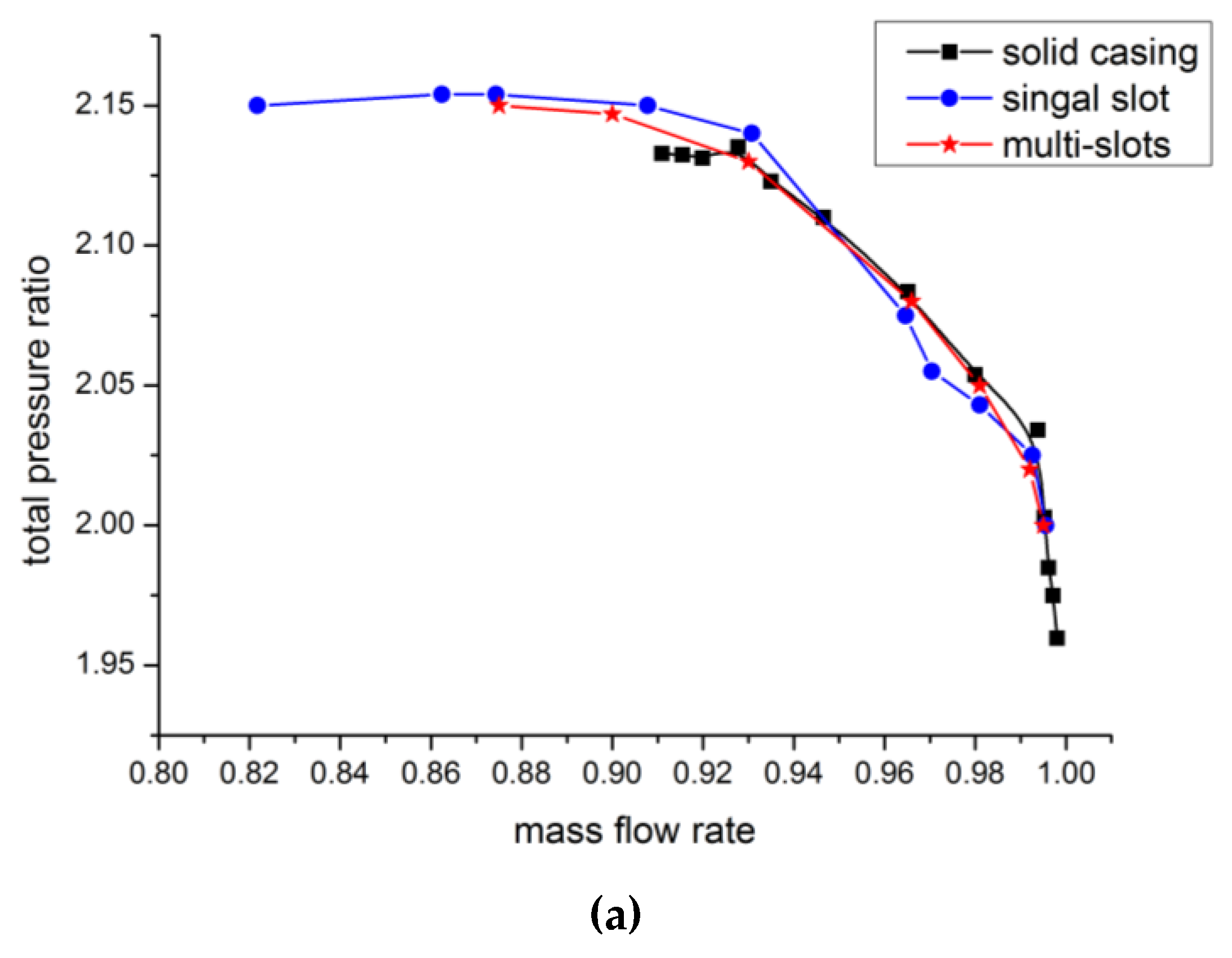
3.2.1. The Influence on Compressor Characteristic Curves

The above analysis shows that the slots area has an important influence on the stall margin. Therefore, the following content will study the influence of the slot circumferential interval on compressor performance while keeping the total slot area constant. This paper compares a single slot and three slots in a signal passage under a 20% total slots area ratio.
Figure 18 depicts the total pressure ratio and efficiency curves of the compressor of the solid casing, single slot and multi-slots. It can be seen from the figure that the stall margin under the influence of a single slot is larger than that of multi-slots with a similar efficiency loss.

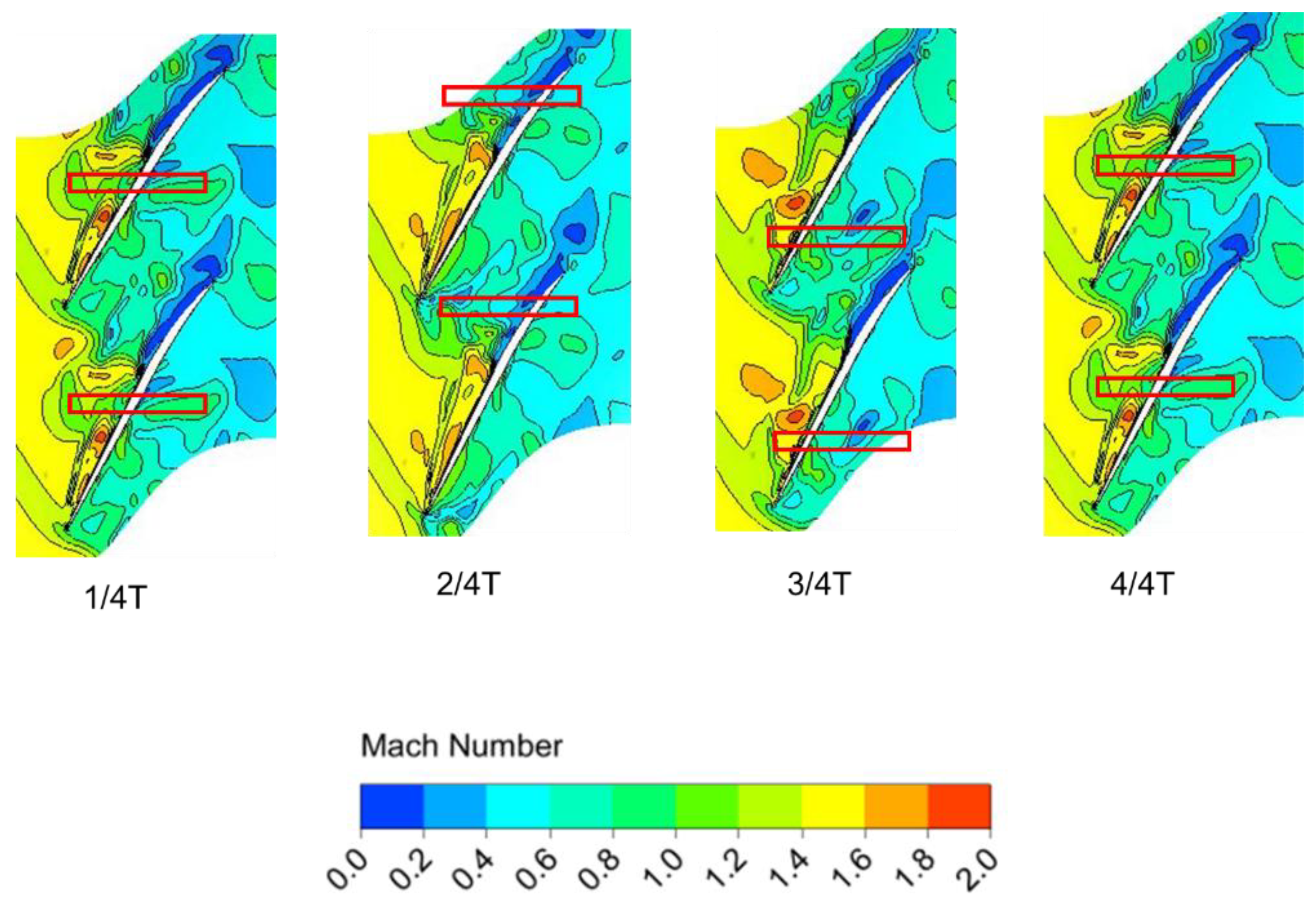
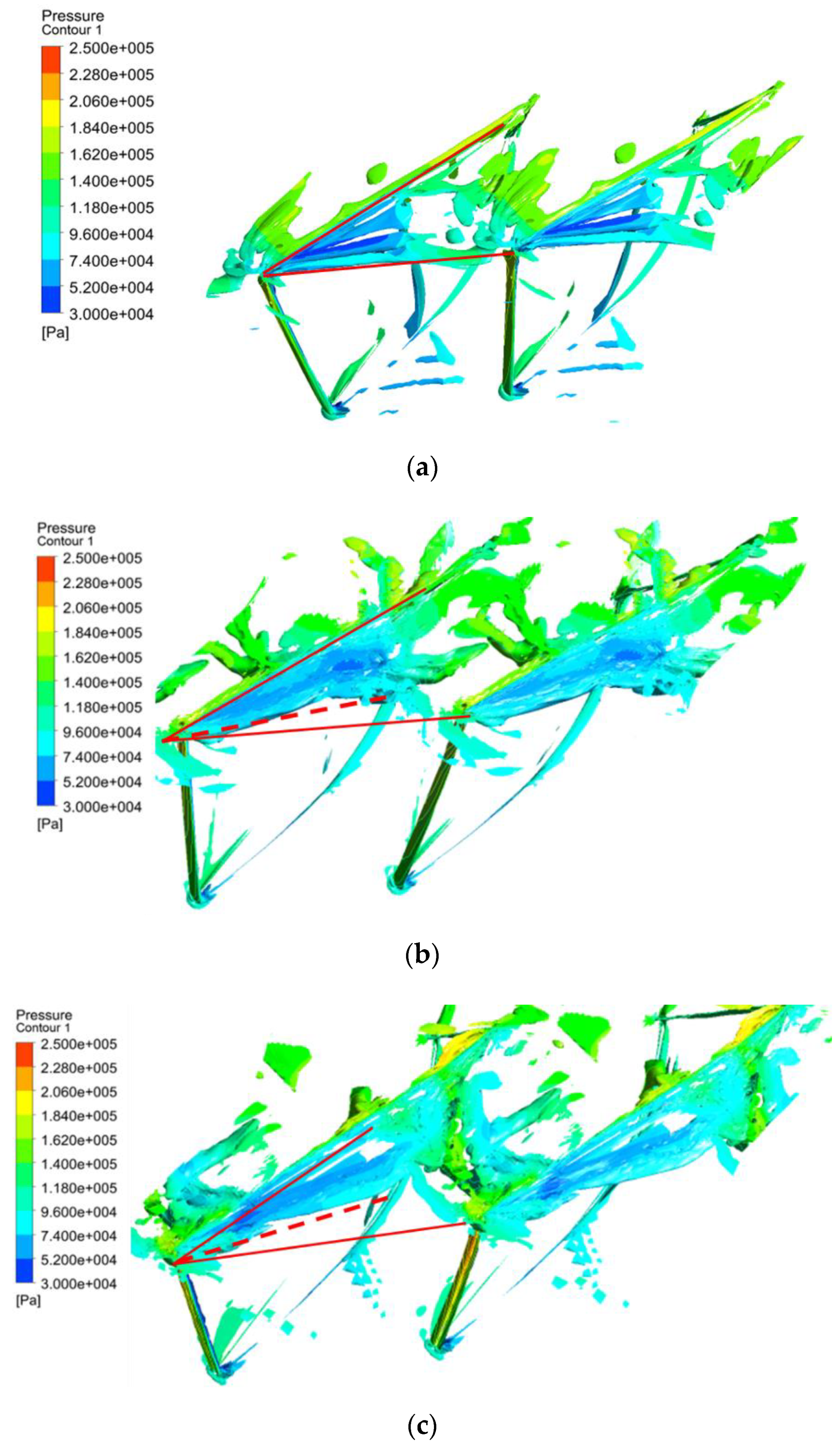
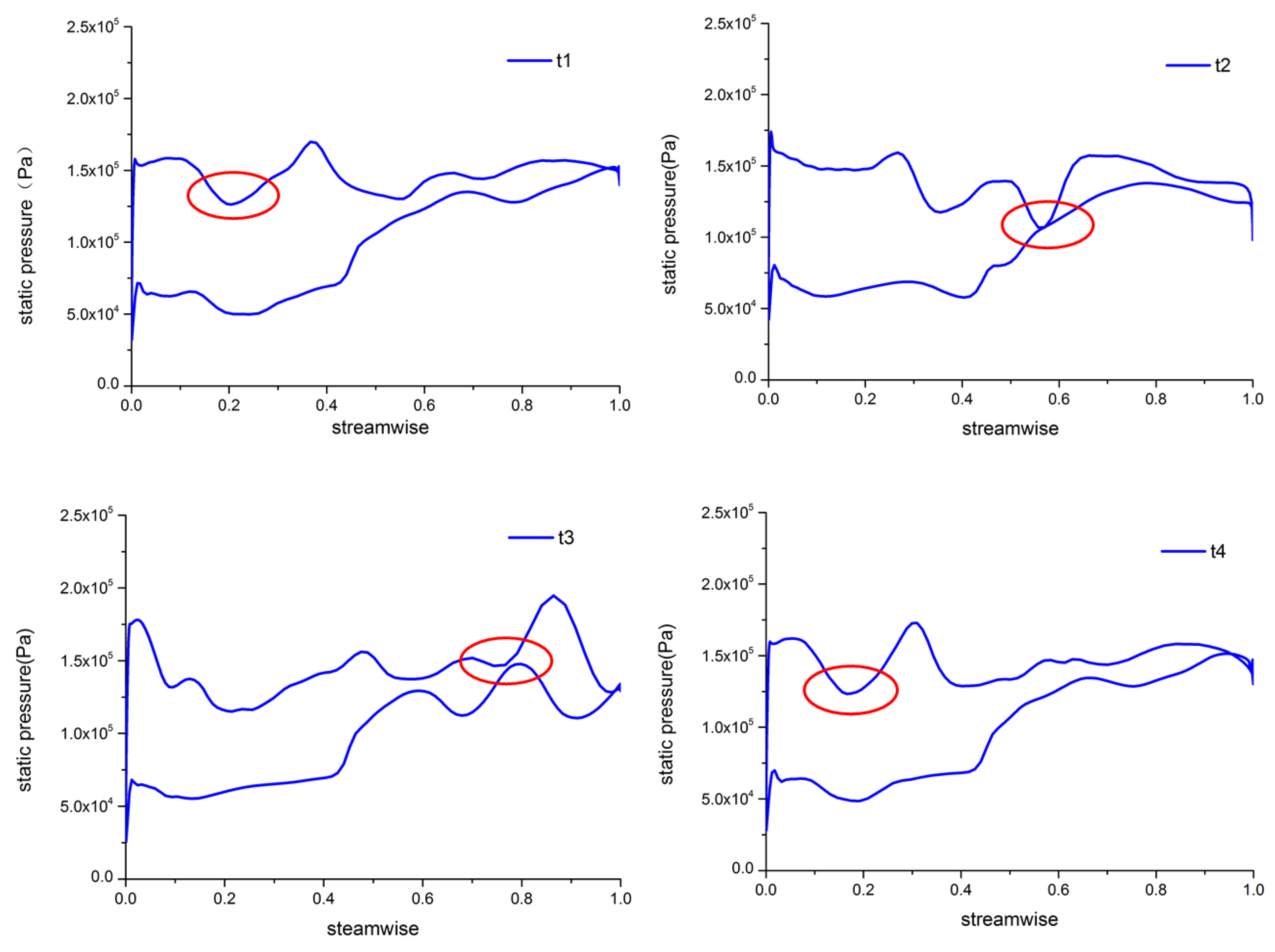
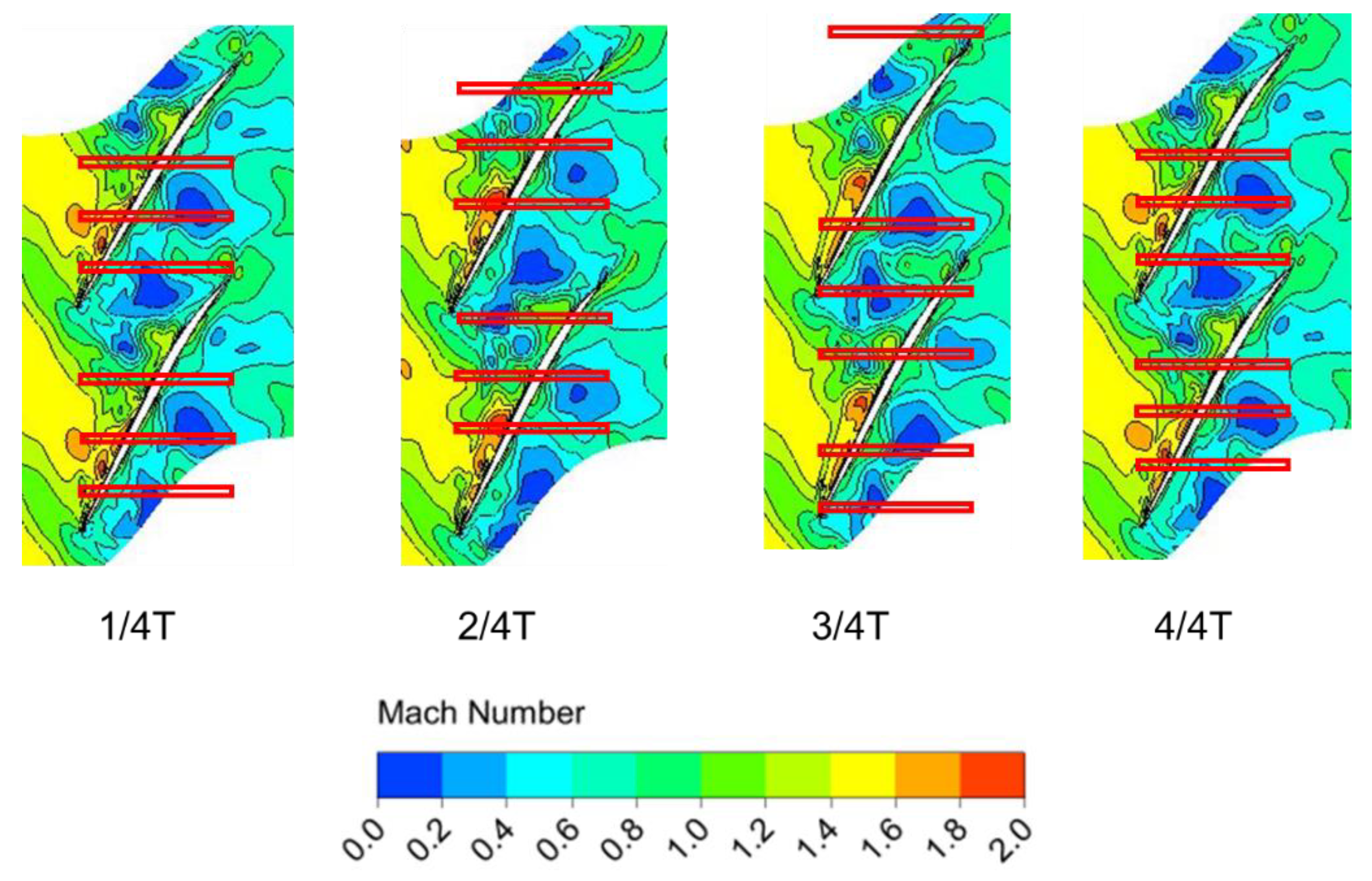
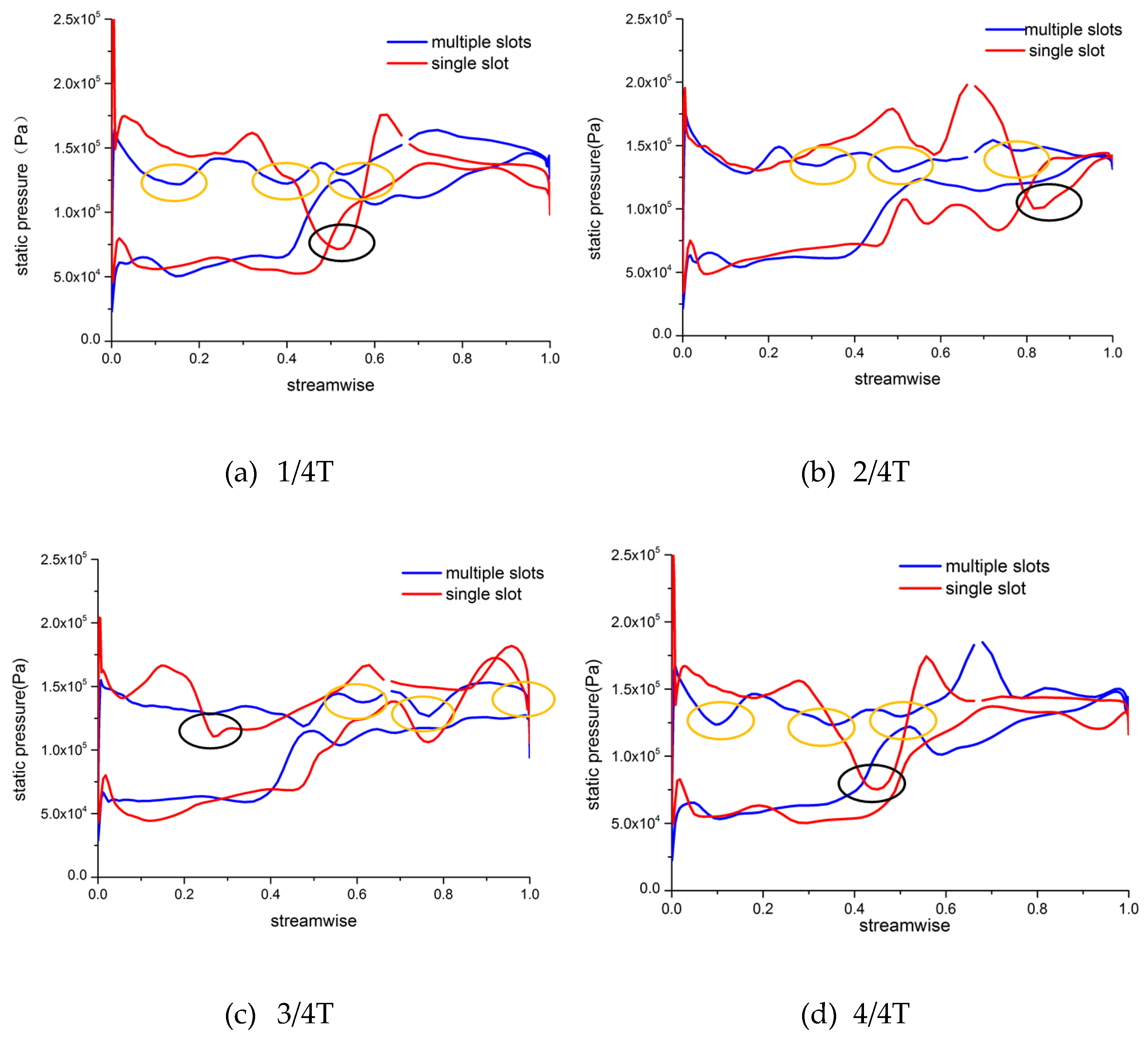
3.2.2. Analysis of Unsteady Tip Flow Field Details

Figure 19 shows Mach number contours in an unsteady period at 99% span of three slots in a passage; T is the period determined by the main frequency of the respective unsteady pressure fluctuation. It can be seen from the figure that the tip leakage vortex forms large-scale low-velocity zones in the middle of the passage after passing through the shock wave, and the size of low-velocity zones is not obviously reduced. Hence, its stall margin extension effect is small.
Figure 20 depicts the unsteady load curves at 99% span under three slots vs. a single slot in a passage. We can conclude that the tip load has a certain drop in many positions under the influence of slots, which are marked by red or yellow circles. However, the magnitude of drop of load is less than that of a single slot in a passage. Due to the arrangement of multiple axial slots in a single passage, the area of each axial slot is greatly reduced, resulting in the momentum exchange in each being weak and the leakage vortex cannot be effectively suppressed.
Therefore, under the premise of a small slot area, in order to achieve a better stall margin improvement, it is necessary to increase the slots’ circumferential interval and reduce the number of slots to enhance the unloading effect of each axial slot and suppress the unsteadiness in the tip region effectively.

4. Conclusions

This paper proposes a novel axial slots casing treatment structure with a large circumferential interval and small opening area. Unsteady numerical simulations are conducted on transonic compressor rotor 37 to study the effect of different axial slots on compressor performance and its mechanism. We can reach the following conclusions:
(1)
The axial slots with a large circumferential interval and small opening area proposed in this paper have a significant stall margin improvement effect. Compared with the traditional axial slots casing treatment, the efficiency loss is greatly reduced;
(2)
The axial slot proposed in this paper can destroy the formation condition of tip’s self-induced unsteadiness and suppress the development of the tip leakage vortex at the near stall condition through decreasing the tip loading periodically. Moreover, this periodical effect plays a dominant role, as opposed to a large-scale momentum exchange, in suppressing the tip leakage vortex compared with the traditional axial slot structure;
(3)
The slot area is proportional to the improvement of the stability margin. Under the same slot area, an excessive number of slots is not conducive to the improvement of the stability margin.

Author Contributions

Z.L. performed the numerical simulation work and wrote the manuscript; G.H. proposed the ideas and research route; O.M. helped the manuscript revision work. All authors have read and agreed to the published version of the manuscript.

Funding

This research was funded by the National Basic Research Program of China (HKCX2020-02-023, J2019-II-0007-0027).

Institutional Review Board Statement

Not applicable.

Informed Consent Statement

Not applicable.

Data Availability Statement

Not applicable.

Acknowledgments

The authors would like to thank the institute of microturbine engine of Nanjing University of Aeronautics and Astronautics for their devotion to this research.

Conflicts of Interest

The authors declared that they have no conflicts of interest regarding this work. We declare that we do not have any commercial or associative interest that represents a conflict of interest in connection with the work submitted.

References

  1. Day, I. Stall, Surge and 75 Years of Research. J. Turbomach. 2015, 138, 011001. [Google Scholar] [CrossRef]
  2. Christensen, D.; Cantin, P.; Gutz, D.; Szucs, P.N.; Wadia, A.R.; Armor, J.; Dhingra, M.; Neumeier, Y.; Prasad, J.V.R. Development and Demonstration of a Stability Management System for Gas Turbine Engines. J. Turbomach. 2008, 130, 99–107. [Google Scholar] [CrossRef]
  3. Wilke, I.; Kau, H.P. A Numerical Investigation of the Flow Mechanisms in a HPC Front Stage with Axial Slots. In Proceedings of the ASME Turbo Expo, Collocated with the International Joint Power Generation Conference, Atlanta, GA, USA, 16–19 June 2003. [Google Scholar]
  4. Smith, G.D.J.; Cumpsty, N.A. Flow Phenomena in Compressor Casing Treatment. J. Eng. Gas Turbines Power 1984, 106, 532–541. [Google Scholar] [CrossRef]
  5. Danner, F.C.T.; Kau, H.P.; Müller, M.M.; Schiffer, H.-P.; Brignole, G.A. Experimental and Numerical Analysis of Axial Skewed Slot Casing Treatments for a Transonic Compressor Stage. In Proceedings of the ASME Turbo Expo: Power for Land, Sea, & Air, Orlando, FL, USA, 8–12 June 2009. [Google Scholar]
  6. Takata, H.; Tsukuda, Y. Stall Margin Improvement by Casing Treatment—Its Mechanism and Effectiveness. J. Eng. Power. 1977, 99, 121–133. [Google Scholar] [CrossRef]
  7. Moore, R.D.; Kovich, G.; Blade, R.J. Effect of Casing Treatment on Overall and Blade-Element Performance of a Compressor Rotor; NASA: Washington, DC, USA, 1971.
  8. Huang, G.; Lu, W.; Zhu, J.; Fu, X.; Wang, J. A nonlinear dynamic model for unsteady separated flow control and its mechanism analysis. J. Fluid Mech. 2017, 826, 942–974. [Google Scholar] [CrossRef]
  9. Jie, C.; Lu, W.; Huang, G.; Zhu, J.; Wang, J. Research on Pulsed Jet Flow Control without External Energy in a Blade Cascade. Energies 2017, 10, 2004. [Google Scholar]
  10. Sun, D.; Sun, X.; Liu, X.; Lin, F.; Qun, N.C. Effect of Novel Casing Treatment on the Suppression of Stall Precursor in a Transonic Compressor. In Proceedings of the ASME Turbo Expo 2014: Turbine Technical Conference and Exposition, Volume 2D: Turbomachinery, Düsseldorf, Germany, 16–20 June 2014. [Google Scholar]
  11. Dong, X.; Sun, D.; Li, F.; Sun, X. Stall Margin Enhancement of a Novel Casing Treatment Subjected to Circumferential Pressure Distortion. Aerosp. Sci. Technol. 2018, 73, 239–255. [Google Scholar] [CrossRef]
  12. Suder, K.L. Experiment and Computational Investigation of the Tip Clearance Flow in a Transonic Axial Compressor Rotor. ASME J. Turbomach. 1996, 118, 218–229. [Google Scholar] [CrossRef] [Green Version]
  13. Zhang, H.; Chu, W.; Wu, Y. Numerical Investigation of the Circumferential Grooved Casing Treatment and Analysis of the Mechanism of Improving Stall Margin. Mech. Sci. Technol. Aerosp. Eng. 2010, 25, 5815–5822. [Google Scholar]
  14. Yamada, K.; Furukawa, M.; Nakano, T. Unsteady Three-Dimensional Flow Phenomena Due to Breakdown of Tip Leakage Vortex in a Transonic Axial Compressor Rotor. In Proceedings of the ASME Turbo Expo: Power for Land, Sea, & Air, Vienna, Austria, 14–17 June 2004. [Google Scholar]
  15. Du, J.; Lin, F.; Zhang, H.; Chen, J. Numerical Investigation on the Self-Induced Unsteadiness in Tip Leakage Flow for a Transonic Fan Rotor. J. Turbomach. 2010, 132, 021017.1–021017.9. [Google Scholar] [CrossRef]
  16. Juan, D.U.; Jichao, L.I.; Kai, W.; Lin, F.; Nie, C. The Self-induced Unsteadiness of Tip Leakage Flow in an Axial Low-Speed Compressor with Single Circumferential Casing Groove. J. Therm. 2013, 22, 565–572. [Google Scholar]
Figure 1. Measurement positions of the experiment (from NASA).
Energies 14 06181 g001
Figure 2. The model of the novel axial slot casing treatment.
Energies 14 06181 g002
Figure 3. Computational domain mesh.
Energies 14 06181 g003
Figure 4. Characteristic curves for calculation and experiment. (a) Total pressure ratio characteristic curves; (b) efficiency characteristic curves.
Energies 14 06181 g004
Figure 5. Span distribution of total pressure ratio and total temperature ratio near the stall point. (a) Span distribution of the total pressure ratio near the stall point; (b) span distribution of the total temperature ratio near the stall point.
Energies 14 06181 g005
Figure 6. Span distribution of the total pressure ratio and total temperature ratio at the peak efficiency point (a) span distribution of the total pressure ratio at the peak efficiency point; (b) span distribution of the total temperature ratio at the peak efficiency point.
Energies 14 06181 g006aEnergies 14 06181 g006b
Figure 7. The relative Mach number distribution of the 95% B2B surface at the near stall point (a) numerical result; (b) experimental result from NASA.
Energies 14 06181 g007
Figure 8. Characteristic curves for solid wall casing and axial slots of different areas (a) total pressure ratio characteristic curves; (b) efficiency characteristic curves.
Energies 14 06181 g008
Figure 9. Frequency characteristic of the solid wall casing and axial slots of 10% and 20% area ratios. (a) Solid wall casing; (b) 10% slot area rate; (c) 20% slot area rate.
Energies 14 06181 g009
Figure 10. The positions of monitor points.
Energies 14 06181 g010
Figure 11. Mach number contours at 99% span in an unsteady period for the solid wall casing.
Energies 14 06181 g011
Figure 12. The tip load curves at 99% span in an unsteady period for the solid wall casing.
Energies 14 06181 g012
Figure 13. Mach number contours at 99% span in an unsteady period for 10% axial slots.
Energies 14 06181 g013
Figure 14. Mach number contours at 99% span in an unsteady period for 20% axial slots.
Energies 14 06181 g014
Figure 15. The lambda 2 iso-surface contour of the average pressure in an unsteady period. (a) Solid casing; (b) 10% axial slots; (c) 20% axial slots.
Energies 14 06181 g015
Figure 16. The tip load curves at 99% span in an unsteady period for 10% axial slots.
Energies 14 06181 g016
Figure 17. The tip load curves at 99% span in an unsteady period for 20% axial slots.
Energies 14 06181 g017aEnergies 14 06181 g017b
Figure 18. Characteristic curve for the solid wall casing and axial slots of different circumferential intervals. (a) Total pressure ratio characteristic curves; (b) efficiency characteristic curves.
Energies 14 06181 g018aEnergies 14 06181 g018b
Figure 19. Mach number contours at 99% span in an unsteady period for the casing treatment case of 3 slots per passage.
Energies 14 06181 g019
Figure 20. The tip load curves at 99% span for the casing treatment case of 3 slots per passage.
Energies 14 06181 g020
Table 1. The basic parameters of rotor 37.
ParameterValue
Number of blades36
Design speed (r/min)17188.7
Design tip speed(m/s)454.14
Hub/tip radius ratio0.7
Tip solidity1.288
Design mass flow(kg/s)20.188
Design total pressure ratio2.106
Design adiabatic efficiency0.877
Table 2. The parameters of axial slots.
Slots Area Rate εDepth of Slots (mm)Number of Slots Per Passage
10%5.61
15%5.61
20%5.61 and 3
Table 3. SMI and peak efficiency loss value under the influence of different slot area ratios.
Slots Area Rate εStall Margin Increasement (%)Peak Efficiency Loss (%)
10%6.50.47
15%8.460.588
20%11.80.719
Publisher’s Note: MDPI stays neutral with regard to jurisdictional claims in published maps and institutional affiliations.

