Article

Multi-Port and -Functional Power Conditioner and Its Control Strategy with Renewable Energy Access for a Railway Traction System

1
College of Electrical and Information Engineering, Hunan University, Changsha 410000, China
2
State Grid Changde Electric Power Company, Changde 415000, China
*
Author to whom correspondence should be addressed.
Energies 2021, 14(19), 6146; https://doi.org/10.3390/en14196146
Submission received: 2 August 2021 / Revised: 17 September 2021 / Accepted: 22 September 2021 / Published: 27 September 2021
(This article belongs to the Special Issue Frontier in Special Power Conversion Systems and Control)

Abstract

:
To relieve the contradiction between supply and demand, a multi-port power conditioner (MP-PC) and control strategy with renewable energy access for a railway traction system is presented, which is mainly composed of full-bridge-based MMC and isolated DC/DC converters. As for the full-bridge-based MMC, the equivalent model is established and its novel voltage control method is proposed, which can provide a medium/low-voltage DC-link. A renewable energy system is connected to the system through the DC-link, so the MP-PC can achieve on-site consumption and balance between the load power and output power of RESs. Meanwhile, with the proposed control strategy, MP-PC can achieve three-phase power balance control and improve the operation performance of the railway traction system. Finally, the traction power platform and simulation model are established in the lab, and the topology and control strategy of MP-PC are verified effectively.

Graphical Abstract

1. Introduction

Recently, distributed renewable energy systems (RESs), due to their pollution-free and flexible features, have been extensively applied in the various practical fields, such as dc microgrids and electric vehicles [1,2,3,4]. Naturally, wide dissemination of these new power supply modes integrated with RESs has also resulted in re-thinking and reformation in other industries, typically including railway traction power supply systems (TPSSs) [5,6,7]. Moreover, the contradiction between dramatic development and distressed power supply capacity has exacerbated the dilemma of the current high-speed railway TPSS, which urgently needs new methods to achieve balance between the supply and demand. Hence, in order to ease the tension in TPSSs, the conventional TPSS should be transformed to provide access for RESs, eventually realizing the coexistence of them. As for power quality improvement, some railway power conditioners were proposed [8]. A perspective on power quality issues through railway electrification development and investigation of the system requirements for appropriate power quality is presented, and a railway power conditioner integrated with RES access was proposed to achieve the comprehensive management of power quality and RES access [9]. In [10], a hybrid traction power supply system integrated with photovoltaic sources was proposed. Some scholars have attempted to apply energy storage to railway traction systems, which is used to relieve the power pressure of a railway system [11,12].
A typical configuration of a TPSS that facilitates access to RESs, called a VSC-based medium-voltage dc (MVDC) TPSS, was proposed in [6], comprising numerous ac-dc and dc-dc converters. The VSC-based MVDC TPSS, where the existing single-phase 25-kV ac catenary gives way to a 24-kV dc catenary, combines the utility grid and RESs via the dc line to feed the mobile loads. Furthermore, the topology of the converters for traction also makes the corresponding adjustments according to the change of the catenary voltage. Compared to the traditional 25-kV ac system, the advantages of the VSC-based MVDC TPSS can be summarized as follows [7]:
(a)
Improvement of the power quality;
(b)
Catenary network without neutral sections;
(c)
Coexistence of distributed RESs and TPSS;
(d)
Connectivity among railway systems with heterogeneous RESs.
Although the DC traction power supply system has many advantages, achieving the replacement of the railway power supply system in a short time is not realistic. More precisely, the 25-kV AC traction system has become the standard for high-speed railway TPSSs, and the resulting equipment related to the AC 25-kV is almost rigid. Therefore, the 24-kV dc voltage replacing the original electrification principle will lead to a thorough change for TPSS, for instance, the devices of the traction substation, the topology of converters for traction, and settings of the protection equipment. Consequently, it is significant and urgent to propose a new access configuration, embedded into the current TPSS and facilitating the connectivity of heterogeneous RESs without dumping the ac catenary. Therefore, it can alleviate the contradiction of the supply and demand of the energy and manage the inherent power quality problems in high-speed railway TPSSs, including negative-sequence currents and reactive power [13,14,15].
As for the interface topology of RESs and the layout for multi-energy systems, a great deal of investigation has been devoted to achieving the interconnection of multiple voltage-class distribution networks and coexistence of different subsystems [16,17,18,19,20,21]. Later, a new energy delivery and management system based on power electronic transformers (PETs), also called solid state transformers (SSTs), has gradually formed [22,23,24,25,26]. Note that PETs can obtain excellent performance, such as galvanic isolation, reduced space requirement, and full-range control via medium- to high-frequency transformers and power converters. Furthermore, with the development of PETs, a number of topologies have appeared, like three-stage PETs composed of a front end, isolation end, and back end [22,26]. Considering the limitations of traditional PETs, the topology should be connected in series or parallel to promote high-voltage and large-capacity applications of PETs [26]. In [27,28], a cascaded multilevel converter, enlarging the range of the input voltage, was adopted in the front-end stage with several dc/dc converters as the isolation stage. Similarly, a cascaded diode-clamped multilevel converter has been applied for the front-end stage and isolation dc/dc stage [29]. Later, with the proposal of MMC, this topology has been used in PETs to realize modular expansion and high efficiency [30,31]. Besides theoretical research, various meritorious projects based on a multi-level topology have proceeded, such as FREEDM, UNIFLEX, and HEART, which are dedicated to coordinating and optimizing the delivery and management of RESs [17,32,33,34].
Based on the analysis above, a multi-port and -functional power conditioner, applying the PET with a full-bridge MMC topology, for the interconnection of RESs and current AC TPSS is proposed. This conditioner, where the ac ports (similar to the high-voltage ac ports of PET) are connected to the AC traction power arms, and the dc ports (similar to the low-voltage dc links of PET) are connected to RESs, can directly accelerate the energy exchange between RESs and TPSS without abandoning the original power supply mode. In addition, the full-bridge MMC can arbitrarily adjust the voltage on the DC side to facilitate the access of new energy sources. On the one hand, the proposed design can realize the balance between the supply and demand in TPSS by means of an interface of RESs while, on the other hand, the conditioner can regulate the power quality of the railway power system according to the corresponding methods [35,36].
This paper is organized as follows. In Section 2, the basic topology as well as the energy control strategy of the conditioner is briefly introduced. In Section 3, the control method of the isolated dc-dc converter is analyzed in detail. Then, the control method of the full-bridge based MMC for the high-voltage stage is described in Section 4. In Section 5, the experimental process is designed, then the experiment is carried out and finally the experimental conclusion is drawn, which verifies the effectiveness of the topology and its control strategy proposed in this article. The work done in this article and its significance is summarized in Section 6.

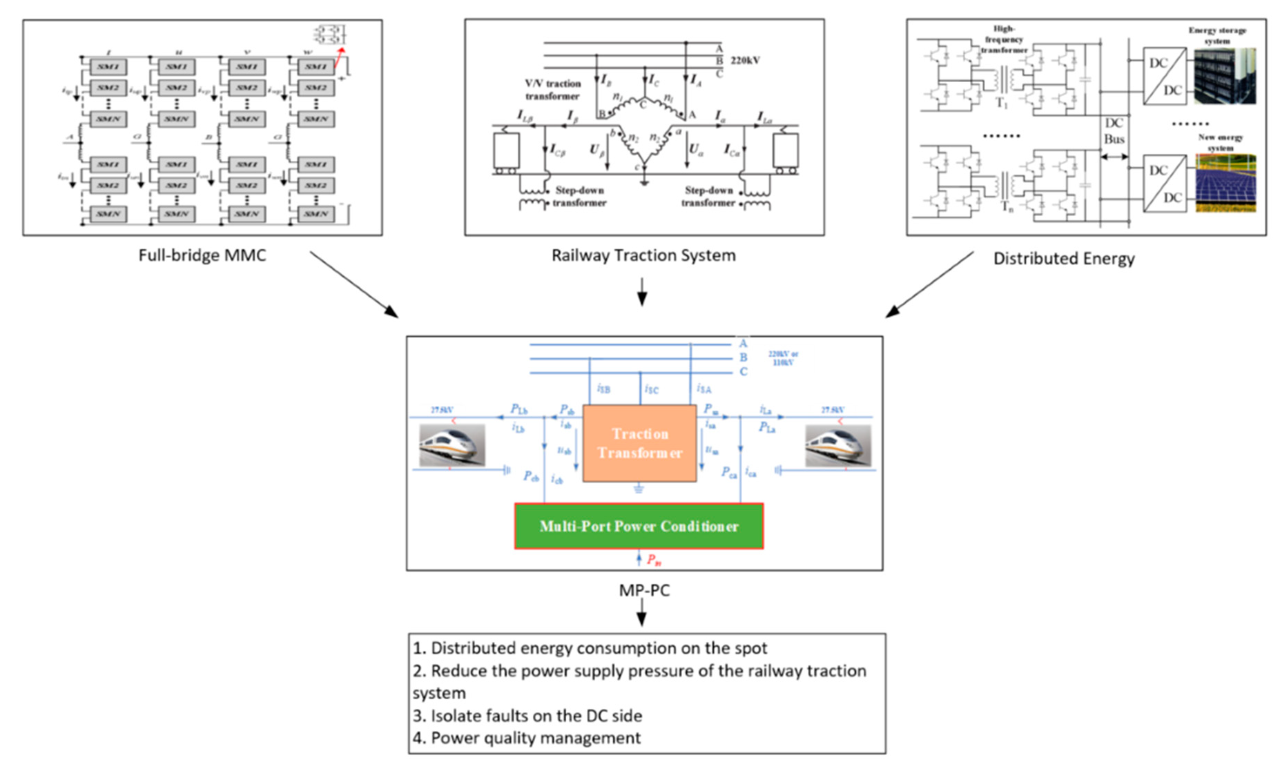
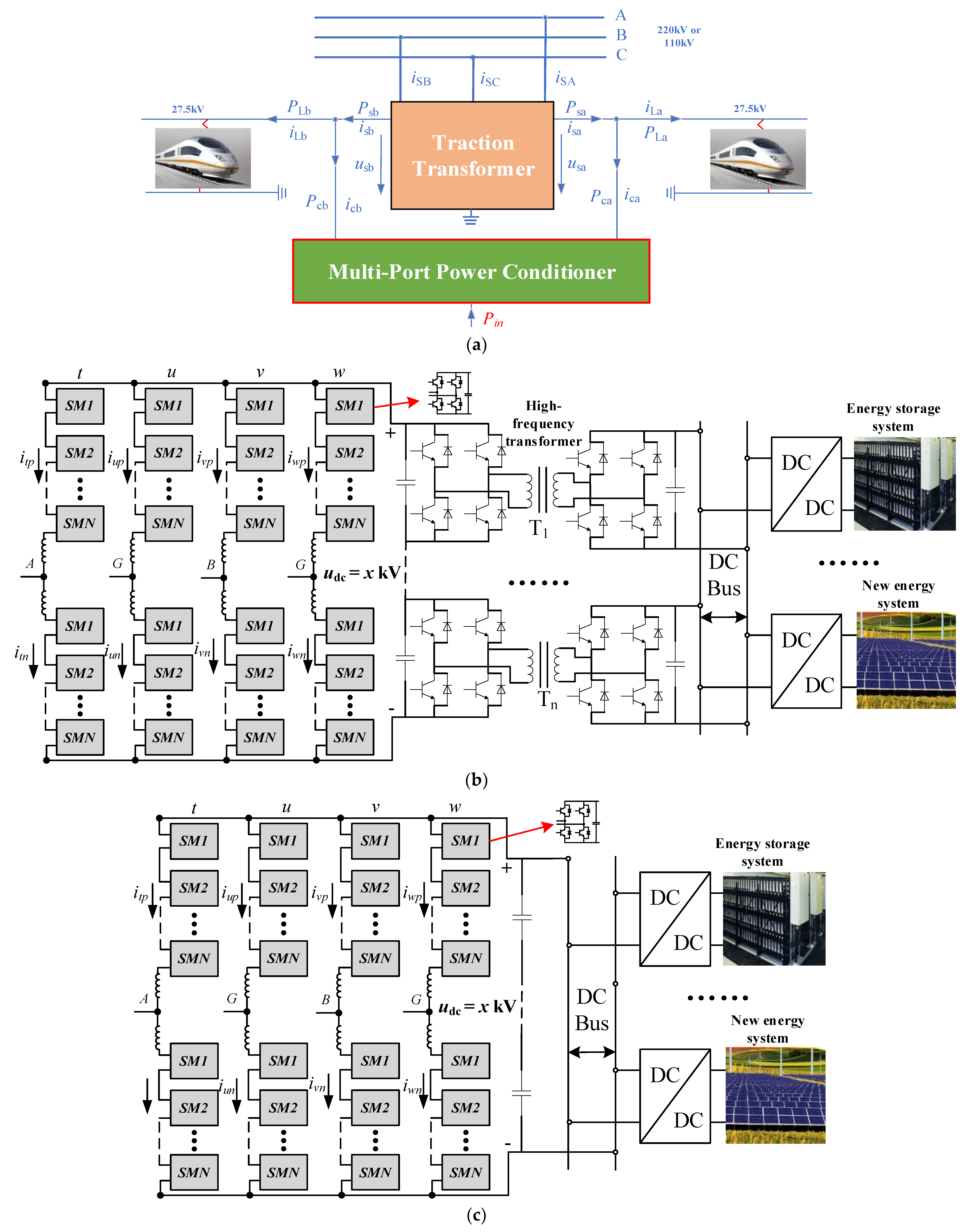
2. Topology and Power Management Strategy of MPPC

In [9], a multi-port railway power conditioner (MP-RPC) with renewable energy access was proposed to realize on-site power consumption and negative-sequence compensation. In this paper, the topology of the multi-port power conditioner (MP-PC) is proposed for better performance, such as a fault isolation capability due to the full bridge MMC. The topology is shown in Figure 1a. The topology consists mainly of a full-bridge-based MMC and an intermediate-stage dc/dc converter. The sub-module of MMC adopts the full-bridge module, and the output port of MMC can generate a lower/medium-voltage DC, which can reduce the input-series number of DC-DC converters. As is known to us, the half-bridge-based MMC cannot output a negative level; therefore, under the same AC-side voltage level, sub-module voltage level, and the same modulation degree, the half-bridge-based MMC cannot output the medium/lower-voltage DC like the full-bridge-based MMC. In addition, the full-bridge-based MMC can also realize the self-blocking function in the DC short-circuit fault. It only needs to block all the switches of the full-bridge sub-module, and then gain re-access after the fault is cleared [37,38]. So, the full-bridge-based MMC can effectively ride through the fault and improve the reliability of MP-PC. The isolated-stage DC-DC converter mainly converts the output medium-voltage DC of MMC into low-voltage DC, and at the same time realizes electrical isolation. The input sides of the DC-DC converters are in series; meanwhile, the other sides of the DAB converters are in parallel, which can form low-voltage DC-Bus for the access of RESs and energy storage systems (ESSs) in the latter stage.
In theory, the DC-link voltage of the full-bridge-based MMC can be stably operated at any set value [0, +∞], so the DC-side voltage of MMC can be controlled at a suitable value to form a common DC-link, which can be directly connected to the PV and ESS. It will not only reduce the intermediate conversion, greatly reducing the cost and volume, but also enhance the operating efficiency of the system, as shown in Figure 1b. However, the disadvantage of Figure 1b is that there is no intermediate isolation. Additionally, if the DC-side voltage is set too low, the DC current will be large at the same power level, which will increase the current stress of the power switches of MMC. In summary, compared with the traditional compensation systems, these proposed MP-PCs have many advantages, such as:
MP-PC can achieve on-site access for RESs along the railway line effectively, and the on-site consumption of RESs’ power, which can mitigate the conflict between the supply of and demand for energy. Meanwhile, through the proper power-conditioning strategy, MP-PC can achieve the active-power transferring and reactive-power compensation of two traction power arms for the three-phase power balance.
Assuming that Pin is the total input power of RESs, PLa and PLb represent the load power of two traction power arms, as shown in Figure 1a. In order to realize the power balance of the three-phase traction grid, the power management strategy of MP-PC is as follows:
When Pin < PLa + PLb, it means that the total power generated by RESs is less than the total power of the locomotive loads. At this time, it is necessary to absorb part of the power from the three-phase traction grid to power the loads and realize the balance of the active power. Similarly, when Pin > PLa + PLb, it means that the total power generated by RESs is greater than the total power of the locomotive loads. At this time, the system can not only supply the locomotive loads, but also deliver part of the active power into the three-phase traction grid. So, generally, the max input power Pin should be lower than the capacity of the traction transformer.
For the purpose of realizing the power balance and power quality control [39] on the three-phase side of the railway traction grid, the expected output power of the two traction arms can be derived as:
P sa = P sb = P La + P Lb P in 2
where Psa and Psb are positive values, indicating that the traction grid will release active power for the loads; meanwhile, Psa and Psb are negative values, indicating that the traction grid will absorb active power. Then, the reference values of the phase-a and -b output power (Pca, Pcb) of MP-PC can be obtained:
{ P ca ref = P sa P La = P La + P Lb P in 2 - P La P cb ref = P sb P Lb = P La + P Lb P in 2 P Lb ,
From the equations above, there is:
P ca ref + P cb ref + P in = 0 ,

3. Topology and Power Management Strategy of MPPC

From the structure above, it can be seen that the full-bridge-based MMC is the core component of MP-PC, responsible for connecting the two-phase traction power arms and adjunct system, managing the power-flow distribution of the system. Here, the equivalent model of the full-bridge-based MMC is established, and a novel voltage balance control method is proposed for MMC, which can provide a stable medium/low-voltage DC-link.

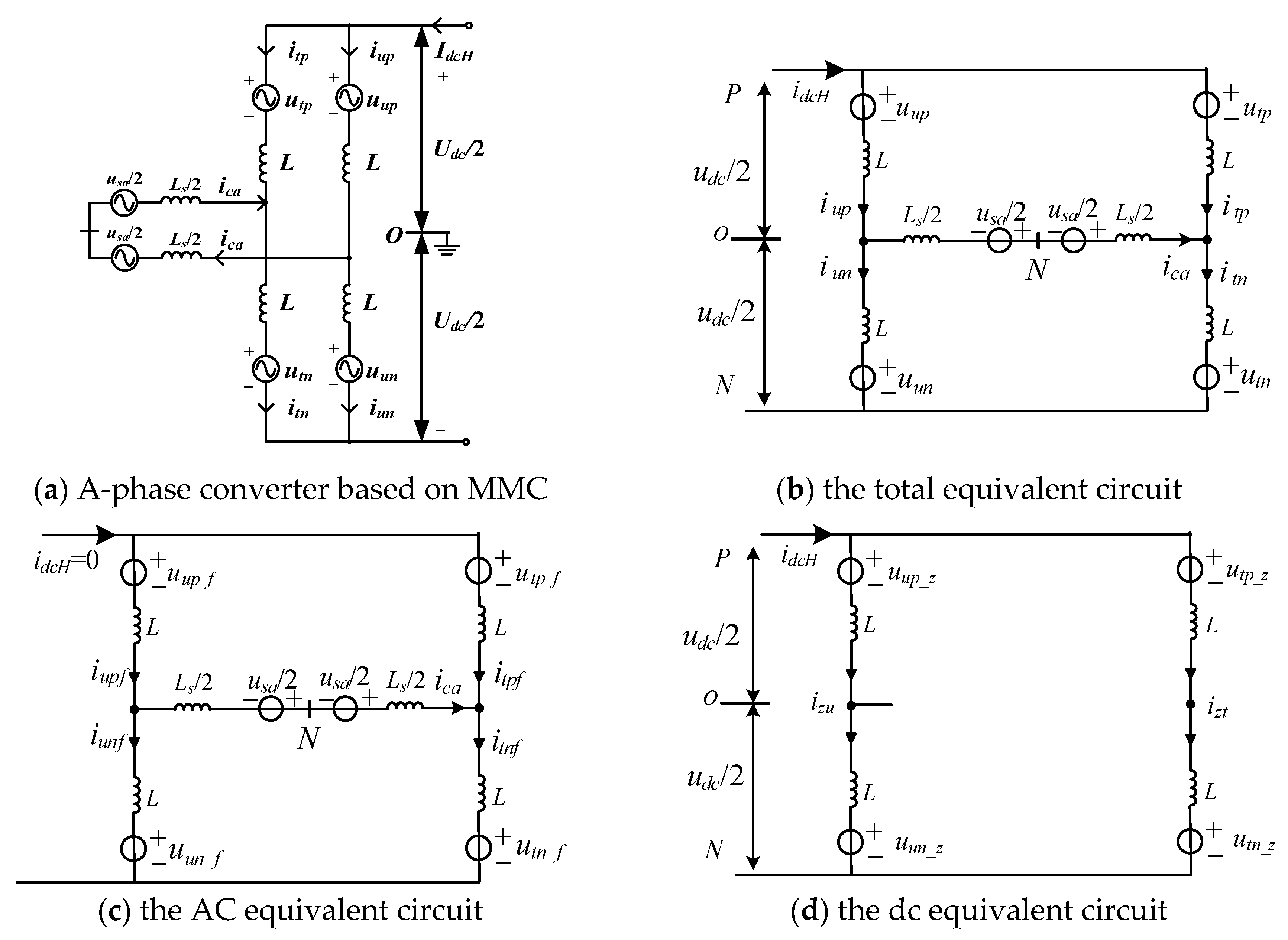
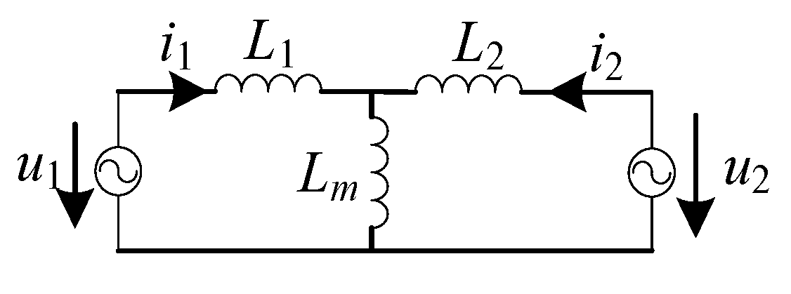
3.1. Equivalent Model of the Full-Bridge-Based MMC Rectifier

Taking the A-phase of MMC as an example, the equivalent circuit of the full-bridge-based MMC is constructed as shown in Figure 2, where usa and ica are the A-phase traction voltage and current, respectively; L is the bridge arm inductor; and Ls is the filter inductor. ukp and ukn (k = t, u) represent the upper and lower bridge arm voltages of the t and u phases of MMC; ikp and ikn represent the upper and lower bridge arm currents of the two phases of MMC; and udc is the output DC voltage of MMC. The full-bridge cell-based bridge arm of MMC can be equivalent to one voltage source. Therefore, the neutral point N of the AC grid can be considered as the reference point, and according to Kirchhoff’s law and Figure 2b, the equations for the upper arm and the lower arm can be respectively obtained as:
{ u s a 2 L s 2 d i c a d t + L d i t p d t + u t p = u d c 2 u n O u s a 2 L s 2 d i c a d t L d i t n d t u t n = u d c 2 u n O { u s a 2 L s 2 d i c a d t L d i u p d t u u p = u d c 2 u n O u s a 2 L s 2 d i c a d t + L d i u n d t + u u n = u d c 2 u n O
In order to maintain the balance between the DC voltage, the neutral point N or the midpoint O of MMC’s dc-link is grounded [40], and if the system is in the symmetric operation: U n O 0 . According to the ac and dc equivalent circuits of the system shown as Figure 2c,d, the voltage and current can be obtained as:
{ u t p = u t p _ z + u t p _ f u t n = u t n _ z + u t n _ f u u p = u u p _ z + u u p _ f u u n = u u n _ z + u u n _ f , { i t p _ f = i u n _ f = i c a / 2 i t n _ f = i u p _ f = i c a / 2 i z t = t z u = I d c H / 2 ,
where u X _ z , u X _ f are the dc and ac components of uX, respectively; i X _ f is the ac components of iX; i z t , i z u are the dc circulating currents of the t, u two-phase bridge arms; and i d c H is the current flowing through dc-link. Ignoring the voltage on the bridge arm inductor and the filter inductor, in the steady state, the total voltage and current of the upper and lower bridge arms of the t, u phases can be obtained as:
{ u t p = u u n = U d c _ r e f 2 u s a 2 u t n = u u p = U d c _ r e f 2 + u s a 2 , { i t p , t n = i d c H 2 i c a 2 i u p , u n = i d c H 2 ± i c a 2 i z t = i t p + i t n 2 ; i z u = i u p + i u n 2 ,
where U dc_ref is the reference value of u d c , and the AC modulation degree M of each cell can be calculated as:
M = U m / 2 N × U S M _ r e f U d c _ r e f / 2 ,
Among them, Um is the peak value of the grid voltage; USM_ref is the voltage reference of the sub-module capacitor; and N is the number of bridge arm sub-modules. According to (6), there is:
N = N d c + N a c = U d c _ r e f / 2 U S M _ r e f + U m / 2 M U S M _ r e f ,
Among them, Ndc is used to generate the output DC component of the medium voltage for MMC, and Nac is used to generate the AC component of the medium voltage, realizing power exchange with the grid voltage. The reference voltage of each bridge arm of MMC contains the DC component Udc_ref/2. Therefore, the output voltages of the upper/lower arms are added together to obtain the medium-voltage DC output Udc_ref.
In the paper, the AC port of MMC is a 27.5 kV AC grid. It is assumed that the capacitor voltage of each sub-module is 750 V, and the MMC is used to output 3 kV medium-voltage DC Bus, i.e., Udc_ref = 3 kV. According to (8), Ndc = 2 is selected. If the AC modulation degree is M = 0.9, then Nac = 29 is selected according to (8). So, 31 full-bridge cells are used for each upper and lower bridge arm of the MMC.
Assuming the grid voltage and current of A phase traction arm are:
{ u s a = U m sin ω t i c a = I m sin ( ω t φ ) ,
Assuming that the two-phase bridge arms are symmetrical, and the parameters are the same, the current will be evenly distributed in each bridge arm in the steady state. The currents of the t-phase upper/lower bridge arm can be expressed as:
{ i t p = I d c H / 2 I m sin ( ω t φ ) / 2 i t n = I d c H / 2 + I m sin ( ω t φ ) / 2 ,
Then, the output power of the AC grid is:
P a c = u s a i c a = U m I m cos φ 2 U m I m cos ( 2 ω t φ ) 2 ,
The power flowing through the MMC DC port can be expressed as:
P d c = u d c i d c H = u d c C d u d c d t ,
where C is the DC-link equivalent capacitance. According to the power balance, if the loss of the MMC is neglected, the steady-state dc power can be expressed as: U d c I d c H = U m I m cos φ / 2 . Meanwhile, secondary fluctuation power is also contained in the DC-link, which will cause a secondary frequency ripple of the DC-link voltage.
Taking the t-phase upper arm as an example, according to (6) and (10), the instantaneous value of the bridge arm power of the t-phase can be obtained as:
P t p = u t p i t p = ( U d c 2 U m sin ω t 2 ) × ( I d c H 2 I m sin ( ω t φ ) 2 ) = U d c I d c H 4 + U m I m cos φ 8 U d c I m sin ( ω t φ ) 4 I d c H U m sin ω t 4 U m I m cos ( 2 ω t φ ) 8 ,
The DC power components can cancel each other out, so the instantaneous value of the bridge arm power can be expressed as:
P t p = U d c I m cos ( ω t φ ) 4 I d c H U m cos ω t 4 U m I m cos ( 2 ω t φ ) 8
From the formula above, Ptp has no DC component, only the AC component, and the energy fluctuation of the t-phase upper arm in one fundamental cycle is zero, indicating the energy and capacitance voltages of the t-phase upper arm are controllable. It is also conceivable that the energy and capacitance voltages of the other bridge arms are controllable, so that the entire MMC converter is controllable. At the same time, it can be seen that the DC-side capacitor voltage of each H-bridge cell not only has a fundamental frequency ripple, but also has a secondary frequency ripple.

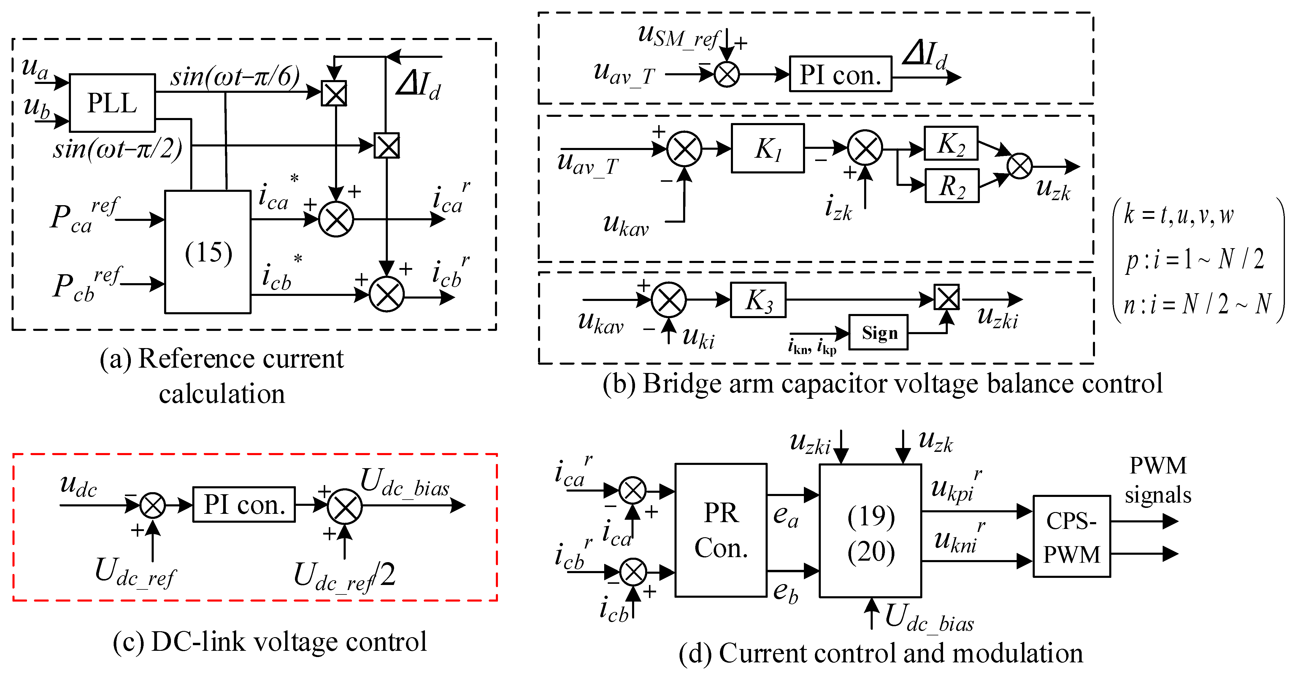
3.2. Control Method of the Full-Bridge-Based MMC Rectifier

The overall control block diagram of MP-PC is shown in Figure 3. Among them, the current command of the traction power supply arm is generated by the control part shown in Figure 3a. The control part shown in Figure 3b is responsible for sub-module voltage balance. The control part shown in Figure 3c is responsible for generating the overall DC voltage command value, and the control part shown in Figure 3d is responsible for generating the PWM command signal.

3.2.1. Reference Current Calculation

According to the power management strategy of MP-RPC, the reference current signals of the a, b-phase of MMC under the v/v traction system [9] can be obtained as follows:
{ i c a * = P ca ref sin ( ω t π / 6 ) / 2 U m + ( P La + P Lb P in ) sin ( ω t + π / 3 ) / 4 U m i c b * = P cb ref sin ( ω t π / 2 ) / 2 U m + ( P La + P Lb P in ) sin ( ω t π ) / 4 U m
where ica* and icb* are the reference currents of phase a and b respectively. Based on these current references, the output active current adjustment signals of the total voltage outer-loop control are obtained (ΔId is multiplied by the synchronization signals of two traction power arms respectively to obtain the active current adjustment signals), and finally the two-phase output current references of MMC icar, icbr can be gained as:
{ i c a r = i c a * + Δ I d sin ( ω t π / 6 ) i c b r = i c b * + Δ I d sin ( ω t π / 2 )

3.2.2. Bridge Arm Capacitor Voltage Balance Control

From the previous analysis, the bridge arm capacitor voltage balance control mainly includes three levels. One is the total voltage balance control of the bridge arm, which is used to absorb AC-side power and balance the power loss of MMC. The second level is the capacitor voltage balance control between the different bridge arms, that is, the energy balance control of each bridge arm of MMC in the horizontal direction. The third level is the capacitor voltage balance control inside the bridge arm, that is, the voltage balance control of the individual sub-module in each arm in the vertical direction, and the control diagram is shown in Figure 3b. First, detecting the capacitor voltage uC_ki of the H-bridge Cell of each bridge arm [k indicates the kth bridge arm (k = t, u, v, w), i indicates the ith sub-module (i = 1~2 N)], the capacitor voltage average value of each bridge arm and the total voltage average value can be obtained as follows:
{ u k a v = 1 2 N u C _ k i / 2 N u a v _ T = k = t , u u k a v / 2
The total voltage balance control: the module voltage reference USM_ref is used to subtract from the total voltage average value uav_T, and the active adjustment signal ΔId for adjusting the total capacitor voltage balance can be obtained by PI control. The output is sent to the reference signal calculation link to obtain two-phase active current adjustment signals.
Horizontal voltage balance control: as shown in the Figure 3b, the error between the capacitor voltage average value of the k-phase bridge arm and uav_T is processed by a regulator K1, which can obtain the circulating current reference of the k-phase bridge arm. The inner-loop current control also adopts a regulator K2 to realize the closed-loop control of the DC signal. At the same time, a second resonant controller R2 is adopted to suppress the second harmonic circulating current, and finally to obtain the circulating voltage control component uzk of the k-phase bridge arm, which is used to achieve the power balance between the bridge arms.
Vertical voltage balance control: the error between the capacitor voltage of each cell and the average voltage value of each bridge arm passes through a regulator K3, and then correction of the symbol function [sign(ikp, ikn)] is used to obtain the voltage balance control component uzki of each sub-module, which is used to control the voltage balance of the individual sub-modules inside the bridge arm.

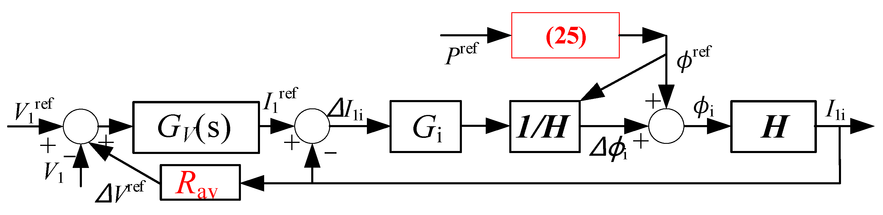
3.2.3. DC-Link Voltage Closed-Loop Control

Since the active power of the latter-stage RESs is injected into the medium/low-voltage DC-link of the pre-stage MMC by the converters, closed-loop control of the medium/low-voltage dc-link is required to maintain a stable voltage. Here, the voltage of the medium-voltage DC-bus is controlled the MMC as shown in Figure 3b. The error of the DC-link voltage reference Udc_ref and the detected value udc is handled with a PI regulator, and then the output is superimposed with half of Udc_ref (as the DC voltage feedforward signal), and the DC offset adjustment signal Udc_bias of the upper and lower bridge arms of each-phase cluster can be obtained. This signal is superimposed on the AC modulation signal of the H-bridge cell of each bridge arm. Through the PWM modulation link, each H-bridge cell can output a stable and equal DC offset, achieving the closed-loop control of the DC-link voltage.

3.2.4. Current Closed-Loop Control and Modulation

In order to make the output AC currents ica and icb of the a and b phases of MMC accurately track the current references, quasi-PR control is used here as follows:
{ e a = G P R ( i ca r i c a ) e b = G P R ( i cb r i c b )
where GPR is the transfer function of the PR controller. According to the above analysis, the output ea, Udc_bias, kth-phase (k = t, u, v, w) voltage balance control command uzk and the ith submodule voltage balance control command uzki are added together, and then divided by NUSM_ref to achieve normalization. Finally, the modulation signal of each H-bridge cell of each bridge arm can be obtained and sent to the CPS-PWM link, and then the corresponding AC and DC signals can be output. Totally, the sub-module modulation waves of the a-phase of MMC can be obtained as (19). Similarly, the modulation wave of each sub-module of the b-phase can be obtained as (20):
{ u tpi r = 1 N U S M _ r e f ( U d c _ b i a s e a 2 u s a 2 + u z t + u z t i )   ( i = 1 ~ N / 2 ) u tni r = 1 N U S M _ r e f ( U d c _ b i a s + e a 2 + u s a 2 + u z t + u z t i )   ( i = N / 2 + 1 ~ N ) u upi r = 1 N U S M _ r e f ( U d c _ b i a s + e a 2 + u s a 2 + u z u + u z u i )   ( i = 1 ~ N / 2 ) u uni r = 1 N U S M _ r e f ( U d c _ b i a s e a 2 u s a 2 + u z u + u z u i )   ( i = N / 2 + 1 ~ N )
{ u vpi r = 1 N U S M _ r e f ( U d c _ b i a s e b 2 u s b 2 + u z v + u z v i )   ( i = 1 ~ N / 2 ) u vni r = 1 N U S M _ r e f ( U d c _ b i a s + e b 2 + u s b 2 + u z v + u z v i )   ( i = N / 2 + 1 ~ N ) u wpi r = 1 N U S M _ r e f ( U d c _ b i a s + e b 2 + u s b 2 + u z w + u z w i )   ( i = 1 ~ N / 2 ) u wni r = 1 N U S M _ r e f ( U d c _ b i a s e b 2 u s b 2 + u z w + u z w i )   ( i = N / 2 + 1 ~ N )

4. Operation Principle and Control of DC/DC Converters

From the structure above, it can be seen that the intermediate isolated DC/DC converter is another key component of MP-PC, responsible for connecting the pre- and post-stage subsystems. According to [41], the equivalent model of the dual active bridge (DAB) converter is shown in Figure 4.
The power is delivered between two ports:
P 12 = ϕ ( π ϕ ) V 1 V 2 A
where A = 2π2fs(L1 + L2); I1 and I2 are the equivalent DC current of two ports; V1 and V2 are the equivalent DC voltage; L1 and L2 are leakage inductors; P12 is the active power transferred between two ports; and ϕ is the phase-shift angle. According to the equation above, assuming that the delivered power is fixed, there is a unique solution for the unknown variable (ϕ). Since the phase-shift range of ϕ is between (−π/2, π/2), according to the solution principle of the quadratic equation, it can be found using:
ϕ = { π π 2 4 A P 12 V 1 V 2 } / 2
According to (22), P12 < V1V2/8fs(L1 + L2) must be met. That is to say, the maximum power transferred between two ports should be less than V1V2/8fs(L1 + L2). In this way, if the rated transmission power has been set, the phase-shift angle ϕ of the output AC voltage of the port can be calculated, thus a rapid power response can be achieved.
In order to establish the small-signal model of the DC/DC converter, it is assumed that the system is stable at the operating point D, where ΔI1 denotes the current deviation and Δϕ denotes the deviation of the phase-shift angle. According to the power transmission model, the expressions of the steady component and the deviation component can be derived respectively. If the quadratic terms of the deviation are ignored:
( I 1 D + Δ I 1 ) V 1 = ϕ D ( π ϕ D ) V 1 V 2 A + Δ ϕ ( π 2 ϕ D ) V 1 V 2 A
The following equation can be obtained:
{ I 1 D = ϕ D ( π ϕ D ) V 2 A Δ I 1 = ( π 2 ϕ D ) V 2 A Δ ϕ = H Δ ϕ H = ( π 2 ϕ D ) V 2 A
From the equation above, the small-signal transfer function H of the DC/DC converter can be obtained. On this basis, the control block diagram of the DC/DC converter can be constructed as shown in Figure 5. The voltage and current dual-loop control is adopted. The voltage outer-loop is used to control and maintain the low-voltage DC-bus, where the intermediate DC-bus of the DC/DC converters is controlled by the MMC-based PWM rectifier. The current inner-loop is adopted to realize closed-loop control of the current and power. In order to improve the dynamic performance of the system and the adaptability of the control parameters, the control system adopts the feed-forward link 1/H on the basis of the small-signal model as shown in Figure 5.
At the same time, in order to achieve the current and power sharing for the N-parallel system, a virtual impedance Rav-based current-sharing control is adopted here. The output current of each unit is multiplied by the virtual impedance to obtain a correction value ΔVref of the voltage reference signal, which can achieve a fine adjustment of the output current and power of each unit. Meanwhile, according to the rated delivered power Pref, the reference value ϕref of the phase-shift angle can be calculated as follows:
{ ϕ ref = π 2 { 1 1 4 A I ref π 2 V 2 } I ref = P ref / V 1 ref / M
where M represents the number of DC/DC modules. According to ϕref and the output signal Δϕi of the current closed-loop controller, the phase-shift angle ϕi of the DC/DC converter i can be obtained. Since both ϕref and the feed-forward link 1/H are determined by the delivered power in different operating stages, the control parameters will vary with the delivered power, which can enhance the dynamic performance of the system and improve the adaptability of the control parameters.

5. Experiments

To verify the feasibility of the proposed topology and method of MP-PC in the paper, the 1 kV-level v/v TPSS and MP-RPC are established via hardware-in-the-loop (CHIL) experiments. As shown in Figure 6, the main circuit is simulated by the RT-LAB real-time system, and the control system is composed of a digital signal processor (DSP, TMS320F2812). The H-bridge-based MMC rectifier adopts 2 cells for each upper/lower bridge leg. The diode rectifier source is adopted to simulate the photovoltaic (PV) generation system, and the power is injected into the lower-voltage dc-bus through a boost converter. In the middle stage, a dc/dc isolated converter is used, where the ratio of the isolation transformer is 1:1. The dc-link voltage of a single DC/DC converter is set as 200 V at each port, and the switching frequency is set as 10 kHz. The detailed circuit and control parameters are shown in Table 1.

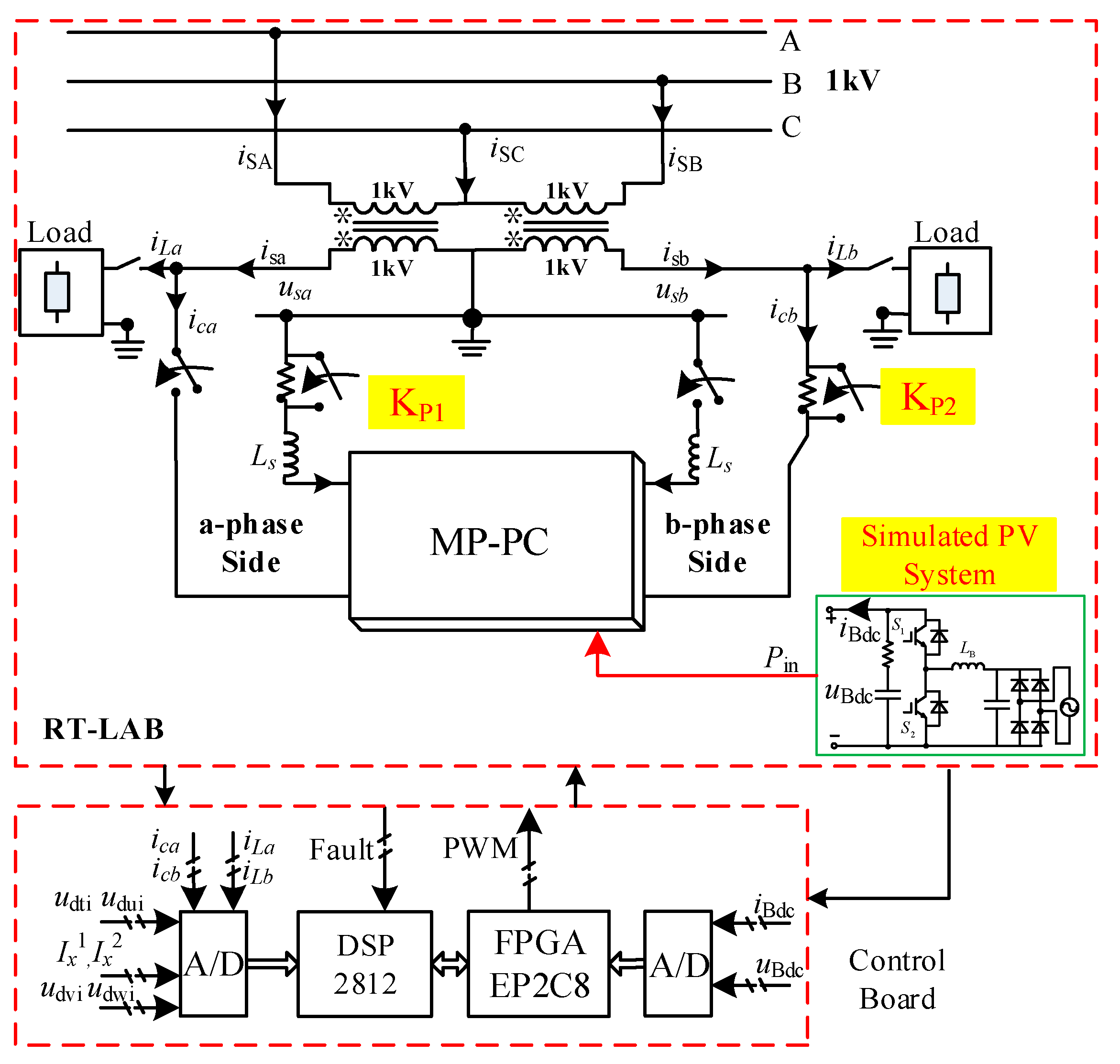
5.1. The Experimental Procedures

(1)
To clarify the purpose of the experiment, the proposed MP-PC aims to balance the power of the railway traction system while absorbing new energy on the spot.
(2)
Corresponding models are built in RT-LAB based on the MP-PC structure in this article, including dual active bridge modules and full-bridge MMC modules.
(3)
The control system is designed based on the model, including the MMC sub-module control part, railway power control part, new energy management part, and design, and the control parameters are debugged.
(4)
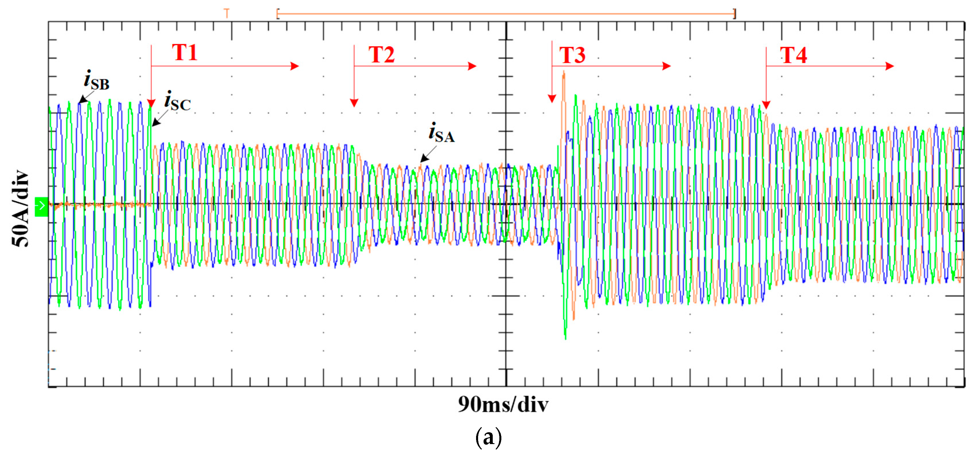
According to the operation situations of the railway traction system, disturbances in the load and new energy modules are set up.
(5)
The operation performance of MP-PC is analyzed according to the experimental waveforms and data, and experimental conclusions are drawn.
In order to verify the topology and control method proposed in this paper, the experiments were performed. First, a 40 kW load is installed on the phase-b traction arm. Before the compensation, the three-phase grid currents are asymmetric as shown in Figure 7a, and there is a large amount of negative sequence current. At the time T1, the conditioning function of MP-PC is enabled. According to the power management strategy of the traction system, some active power and reactive power are transferred and compensated for rapidly by the MMC rectifier. The dc currents idca and idcb flowing through dc-link of MMC are almost opposite, and there is approximately 20 kW of active power transferred from the b-phase traction arm to the other arm. After the compensation, the negative sequence current is greatly reduced, and the two-phase traction currents and three-phase grid currents are basically symmetrical. It can be seen that the dc-link voltage can be controlled at 400 V as shown in Figure 7i, and there is almost no ripple, which is suppressed by the 2nd resonant controller R2. Meanwhile, the submodule capacitor voltages of MMC are maintained at 500 V as shown in Figure 7h, but there are some 1st and 2nd harmonic frequency ripples. The upper/lower arm currents and arm circuiting currents of MMC can be controlled well as shown in Figure 7e,f.
At the time T2, the input power of the simulated PV system jumps from 0 to 15 kW. At this point, the active power injected by RESs is almost absorbed by the intermediate DC/DC converters, delivered to the DC-link of the full-bridge-based MMC, and then the MMC will absorb the power and transfer it to the respective traction arms. The voltage and current waveforms of the two ports of the DC/DC converters are shown in Figure 7i–k. According to the power cooperative strategy of the system, the active power released by the a-phase and b-phase MMC rectifiers are 26.83 and −12.03 kW, respectively, so basically it can track to the power reference of each port. After the power conditioning, the two-phase traction currents and three-phase grid currents are reduced, and the three-phase grid currents are basically symmetrical as shown in Figure 7a,b. Therefore, the injected active power of RESs is effectively absorbed by the MP-PC system, which can reduce the supplied power of the traction network and achieve on-site consumption and balance between the load and RESs. The DC-link voltage of MMC is basically stable at about 400 V.

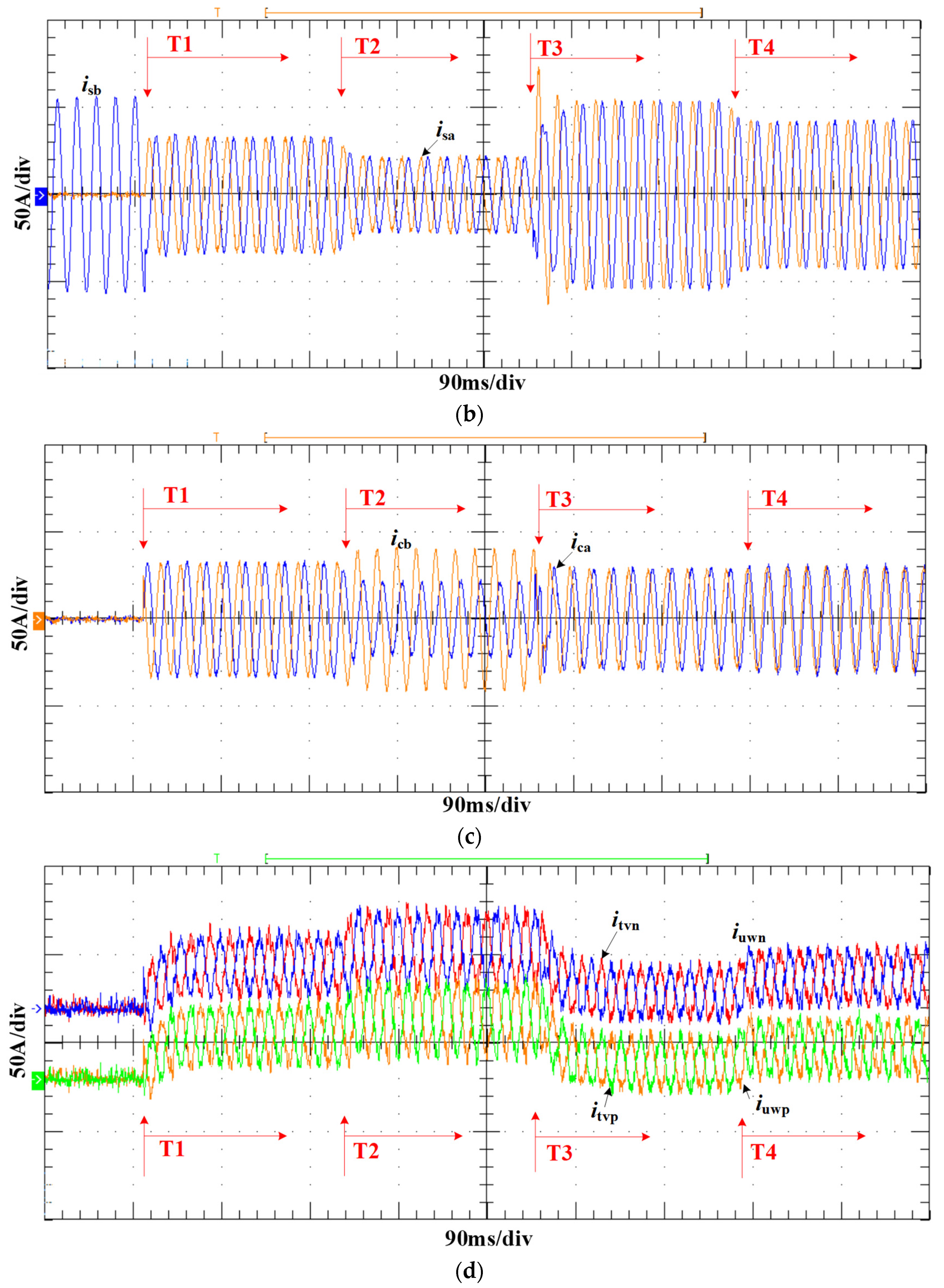
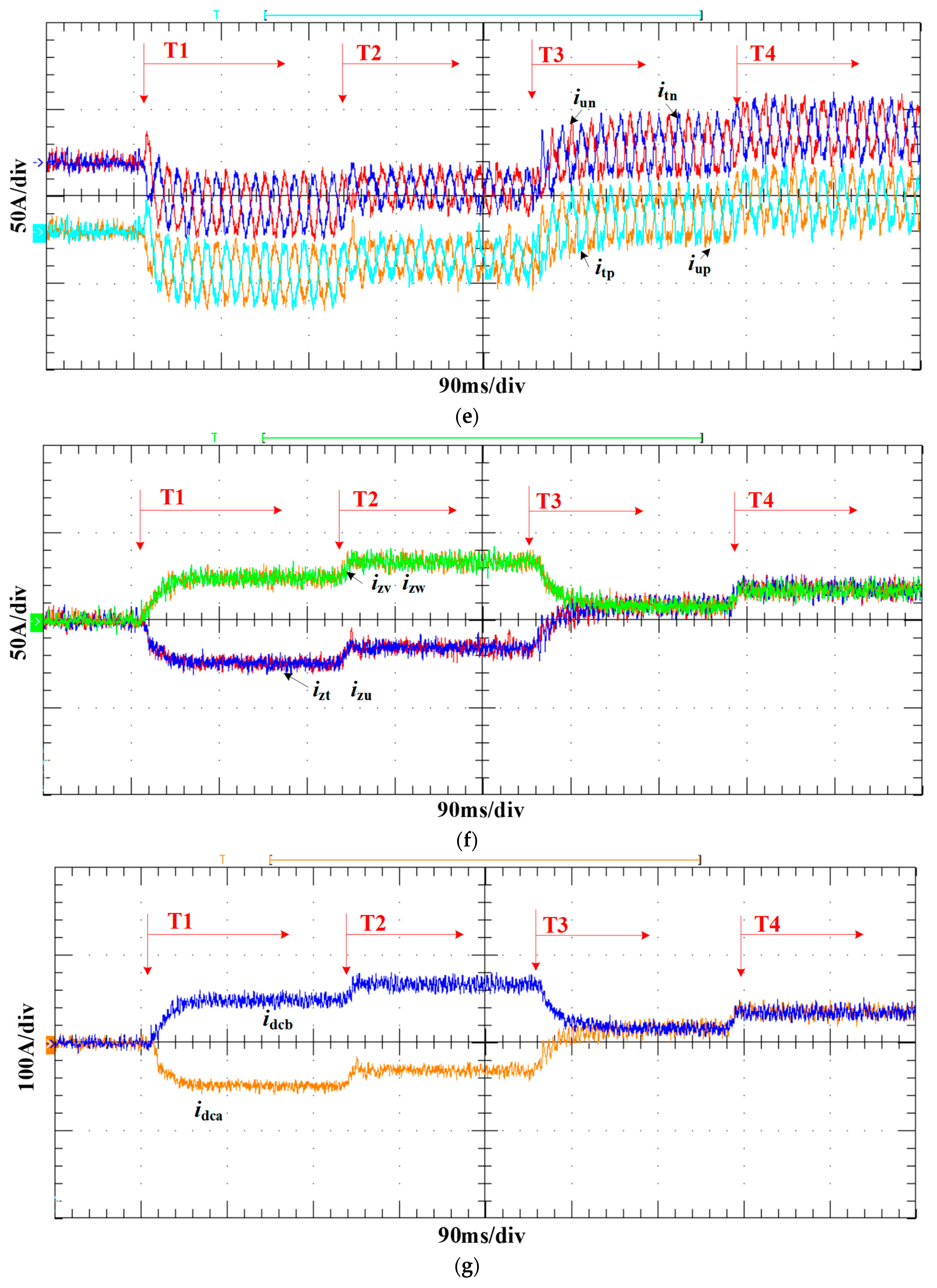
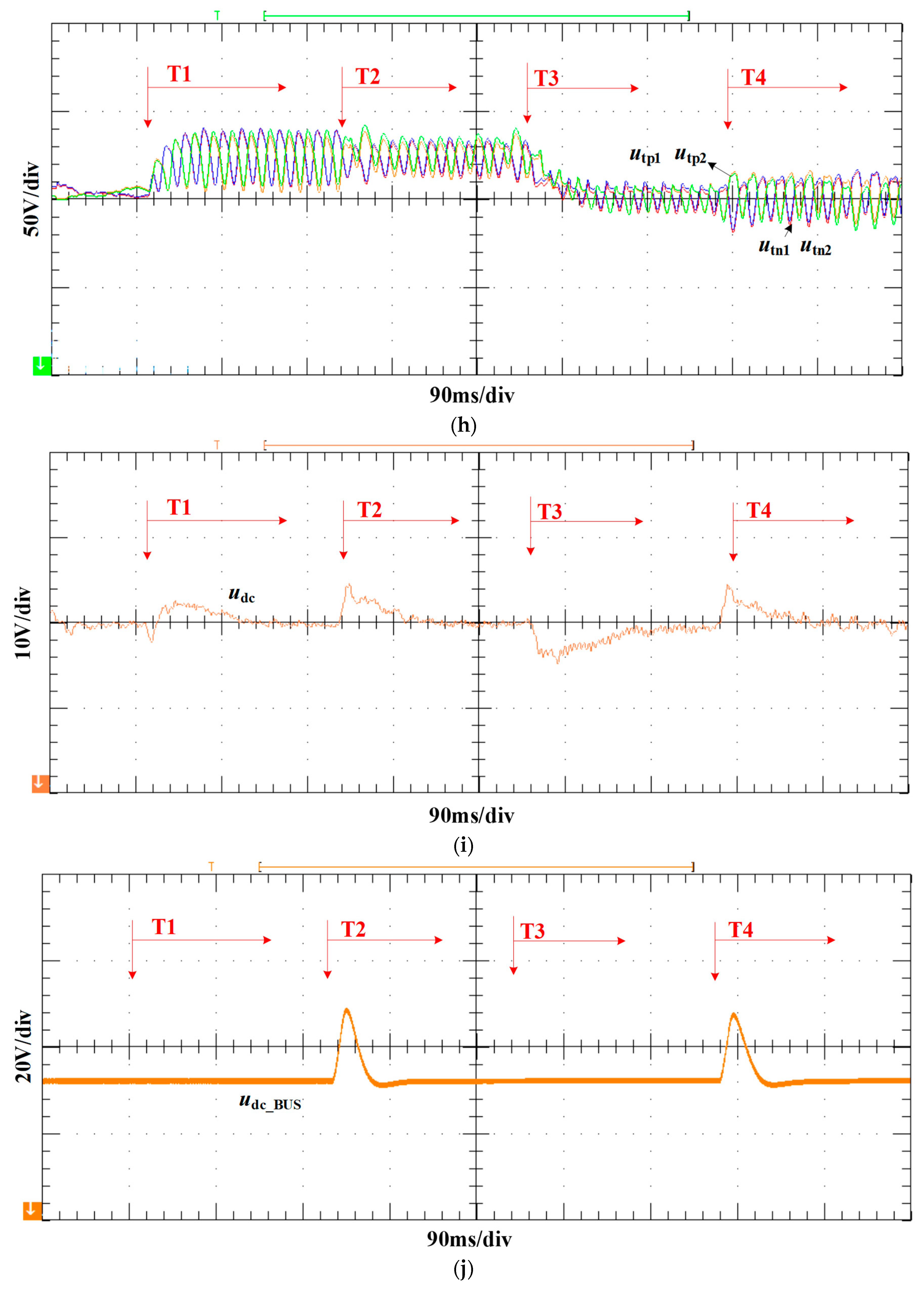
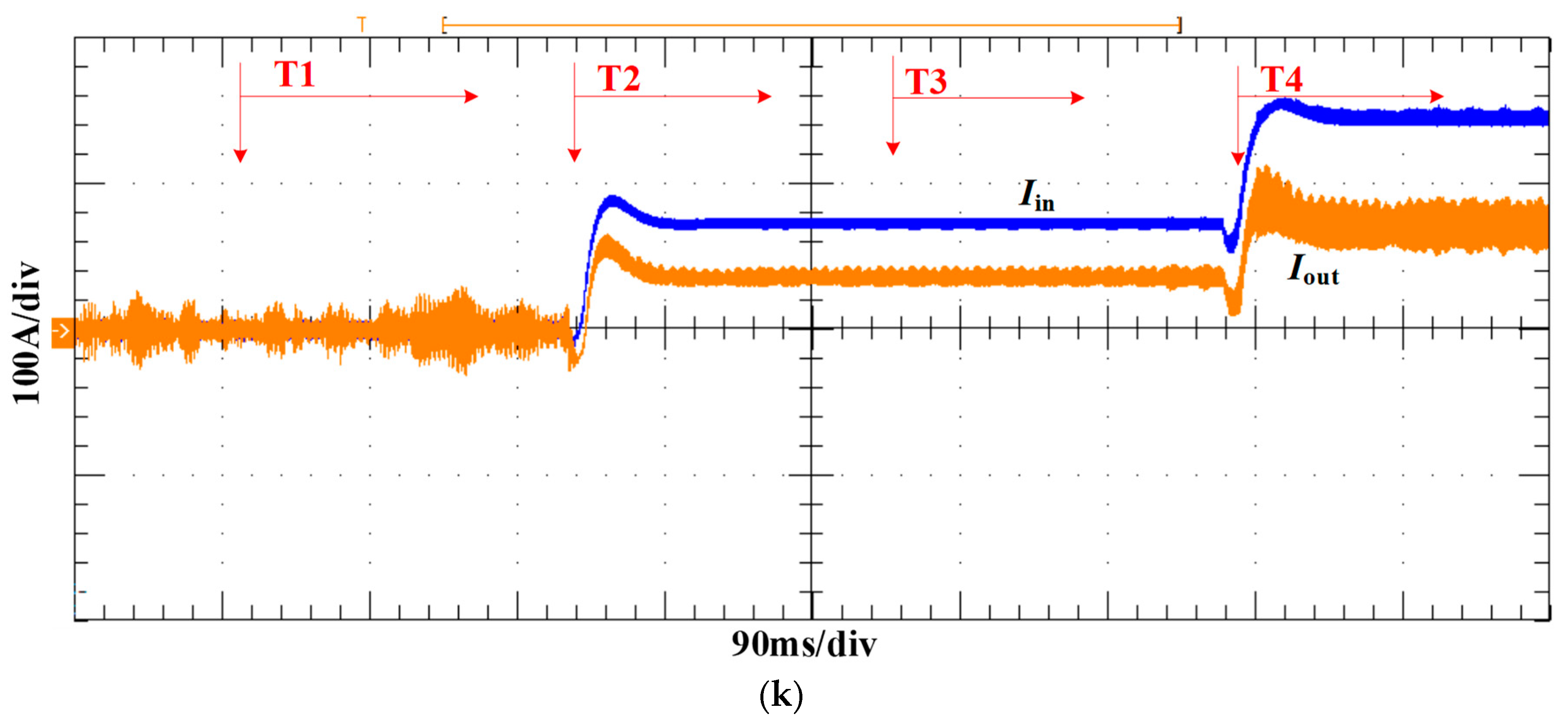
5.2. Case 1: Power Change of Simulated Loads

In order to verify the dynamic control ability of MP-PC for power quality, a 40 kW load is switched into the a-phase traction arm at T3. The experimental waveforms of the system are shown in Figure 7. After T3, according to the power management strategy of the system, the output powers of the MMC are quickly adjusted. The two-phase output powers released by MMC are 7.28 and 7.21 kW, respectively (the references are +7.5 and +7.5 kW). Nearly, it can track the power references of each port, while there are some power losses caused by converters. As seen in Figure 7a,b, the two-phase traction currents and three-phase grid currents greatly increase, indicating that the system needs to absorb more active power from the traction grid to supply the loads. After power conditioning, the two-phase traction currents and three-phase grid currents are symmetrical. In this case, the voltage and currents of the two ports of the intermediate DC/DC converters almost remain the same, as shown in Figure 7j,k. The DC-link voltage and submodule capacitor voltage of MMC can be maintained to be stable.

5.3. Case 2: The Power Change of PV System

In order to verify the power dynamic adjustment ability of MP-PC, the input power of the simulated PV system is increased from 15 kW to 30 kW at T4. The experimental waveforms of the system are shown in Figure 7. After T4, the input power of the simulated PV system is increased, and then the input and output currents of the intermediate DC/DC converters jump. The output power of the DC/DC converters is 28.58 kW, so the output power of the PV system is basically absorbed. The output voltage and current waveforms are shown in Figure 7j,k. At this time, according to the power management strategy of the system, the two-phase output power of MMC is quickly adjusted, and the two-phase released power of MMC is 14.22 and 14.44 kW, respectively. After the power conditioning, the three-phase grid currents are reduced; that is, the injected active power of RESs is effectively absorbed by the MP-PC system, which can reduce the supplied power of the traction network and achieve on-site power consumption and balance as shown in Figure 7a,b. The currents and voltages of MP-PC can be controlled well, so the proposed topology and control method are effective, which can achieve stable operation of the system.

5.4. Experimental Result

From the above two experiments, it can be seen that the MP-PC proposed in this paper can not only effectively transfer the unbalanced power, but also control and balance the fluctuations caused by railway loads. In addition, the output power of the new energy system can be absorbed effectively and directly supplied to the railway loads, improving the utilization rate of the new energy. Furthermore, it can also reduce the pressure put on the power grid by the railway loads.

6. Conclusions

In this paper, a multi-port and -functional power conditioner with renewable energy access for a railway power system was proposed to achieve the goal of on-site consumption and balance between the load power and output power of RESs. According to the traction characteristics of the railway system, the power control strategy for MP-PC was proposed. A novel voltage control strategy of a full-bridge-based MMC rectifier was pro-posed, which can generate a proper medium/low-voltage DC-link for easy access of RESs. Experiments were carried out using RT-Lab platform. Through load fluctuations and photovoltaic output fluctuations, the dynamic control performance of MP-PC was verified through experiments. Finally, from the experimental results, MP-PC can achieve on-site consumption of new energy and three-phase power balance control, obtaining complementarity and benefits between the railway traction system and RESs.

Author Contributions

Conceptualization, F.M. and Y.K.; validation, F.M.; writing—original draft preparation F.M. and Y.K.; writing—review and editing, Y.K., G.H., D.K., C.Z. and Z.W.; funding acquisition, F.M. All authors have read and agreed to the published version of the manuscript.

Funding

National Science Foundation of China under grant 51977067.

Institutional Review Board Statement

Not applicable.

Informed Consent Statement

Not applicable.

Data Availability Statement

Not applicable.

Conflicts of Interest

The authors declare no conflict of interest.

References

  1. Wu, D.; Tang, F.; Dragicevic, T.; Vasquez, J.C.; Guerrero, J. A Control Architecture to Coordinate Renewable Energy Sources and Energy Storage Systems in Islanded Microgrids. IEEE Trans. Smart Grid 2014, 6, 1156–1166. [Google Scholar] [CrossRef] [Green Version]
  2. Fernandez, L.P.; Roman, T.G.S.; Cossent, R.; Domingo, C.M.; Frias, P. Assessment of the Impact of Plug-in Electric Vehicles on Distribution Networks. IEEE Trans. Power Syst. 2011, 26, 206–213. [Google Scholar] [CrossRef]
  3. Guerrero, J.; Blaabjerg, F.; Zhelev, T.; Hemmes, K.; Monmasson, E.; Jemei, S.; Comech, M.P.; Granadino, R.; Frau, J.I. Distributed Generation: Toward a New Energy Paradigm. IEEE Ind. Electron. Mag. 2010, 4, 52–64. [Google Scholar] [CrossRef]
  4. Liu, X.; Loh, P.C.; Wang, P.; Blaabjerg, F.; Tang, Y.; Al-Ammar, E. Distributed Generation Using Indirect Matrix Converter in Reverse Power Mode. IEEE Trans. Power Electron. 2012, 28, 1072–1082. [Google Scholar] [CrossRef]
  5. Leander, P.; Ostlund, S. A Concept for an HVDC Traction System. In Proceedings of the International Conference on Main Line Railway Electrification, London, UK, 25–28 September 1989; pp. 169–173. [Google Scholar]
  6. Gomez-Exposito, A.; Mauricio, J.M.; Maza-Ortega, J.M. VSC-Based MVDC Railway Electrification System. IEEE Trans. Power Deliv. 2013, 29, 422–431. [Google Scholar] [CrossRef]
  7. Yang, X.; Hu, H.; Ge, Y.; Aatif, S.; He, Z.; Gao, S.; Salman, A. An Improved Droop Control Strategy for VSC-Based MVDC Traction Power Supply System. IEEE Trans. Ind. Appl. 2018, 54, 5173–5186. [Google Scholar] [CrossRef]
  8. Xu, Q.; Ma, F.; He, Z.; Chen, Y.; Guerrero, J.M.; Luo, A.; Li, Y.; Yue, Y. Analysis and Comparison of Modular Railway Power Conditioner for High-Speed Railway Traction System. IEEE Trans. Power Electron. 2017, 32, 6031–6048. [Google Scholar] [CrossRef] [Green Version]
  9. Ma, F.; Wang, X.; Deng, L.; Zhu, Z.; Xu, Q.; Xie, N. Multiport Railway Power Conditioner and Its Management Control Strategy with Renewable Energy Access. IEEE J. Emerg. Sel. Top. Power Electron. 2019, 8, 1405–1418. [Google Scholar] [CrossRef]
  10. Deng, W.; Dai, C.; Chen, W.; Gao, S. Experimental Investigation and Adaptability Analysis of Hybrid Traction Power Supply System Integrated with Photovoltaic Sources in AC-Fed Railways. IEEE Trans. Transp. Electrif. 2021, 7, 1750–1764. [Google Scholar] [CrossRef]
  11. Chen, J.; Hu, H.; Ge, Y.; Wang, K.; Huang, W.; He, Z. An Energy Storage System for Recycling Regenerative Braking Energy in High-Speed Railway. IEEE Trans. Power Deliv. 2021, 36, 320–330. [Google Scholar] [CrossRef]
  12. Torkzadeh, R.; Eliassi, M.; Mazidi, P.; Rodriguez, P.; Brnobić, D.; Krommydas, K.F.; Stratigakos, A.C.; Dikeakos, C.; Michael, M.; Tapakis, R.; et al. Synchrophasor Based Monitoring System for Grid Interactive Energy Storage System Control. In Flexitranstore; Németh, B., Ekonomou, L., Eds.; Lecture Notes in Electrical Engineering; Springer International Publishing: Cham, Switzerland, 2020; Volume 610, pp. 95–106. ISBN 978-3-030-37817-2. [Google Scholar]
  13. Zhang, Z.; Wu, B.; Kang, J.; Luo, L. A Multi-Purpose Balanced Transformer for Railway Traction Applications. IEEE Trans. Power Deliv. 2009, 24, 711–718. [Google Scholar] [CrossRef]
  14. Gazafrudi, S.M.M.; Langeroudi, A.T.; Fuchs, E.F.; Al-Haddad, K. Power Quality Issues in Railway Electrification: A Comprehensive Perspective. IEEE Trans. Ind. Electron. 2014, 62, 3081–3090. [Google Scholar] [CrossRef]
  15. Hu, H.; He, Z.; Li, X.; Wang, K.; Gao, S. Power-Quality Impact Assessment for High-Speed Railway Associated with High-Speed Trains Using Train Timetable—Part I: Methodology and Modeling. IEEE Trans. Power Deliv. 2015, 31, 693–703. [Google Scholar] [CrossRef]
  16. Luo, S. A review of distributed power systems part I: DC distributed power system. IEEE Aerosp. Electron. Syst. Mag. 2005, 20, 5–16. [Google Scholar] [CrossRef]
  17. Dragicevic, T.; Lu, X.; Vasquez, J.C.; Guerrero, J. DC Microgrids—Part II: A Review of Power Architectures, Applications, and Standardization Issues. IEEE Trans. Power Electron. 2016, 31, 3528–3549. [Google Scholar] [CrossRef] [Green Version]
  18. Liu, X.; Wang, P.; Loh, P.C. A Hybrid AC/DC Microgrid and Its Coordination Control. IEEE Trans. Smart Grid 2011, 2, 278–286. [Google Scholar] [CrossRef] [Green Version]
  19. Shamsi, P.; Fahimi, B. Dynamic Behavior of Multiport Power Electronic Interface Under Source/Load Disturbances. IEEE Trans. Ind. Electron. 2013, 60, 4500–4511. [Google Scholar] [CrossRef]
  20. Guerrero, J.; Matas, J.; de Vicuña, L.G.; Castilla, M.; Miret, J. Decentralized Control for Parallel Operation of Distributed Generation Inverters Using Resistive Output Impedance. IEEE Trans. Ind. Electron. 2007, 54, 994–1004. [Google Scholar] [CrossRef]
  21. Zhao, C.; Round, S.D.; Kolar, J.W. An Isolated Three-Port Bidirectional DC-DC Converter with Decoupled Power Flow Management. IEEE Trans. Power Electron. 2008, 23, 2443–2453. [Google Scholar] [CrossRef]
  22. Pena-Alzola, R.; Gohil, G.; Mathe, L.; Liserre, M.; Blaabjerg, F. Review of modular power converters solutions for smart transformer in distribution system. In Proceedings of the 2013 IEEE Energy Conversion Congress and Exposition, Denver, CO, USA, 15–19 September 2013; pp. 380–387. [Google Scholar]
  23. Liserre, M.; Buticchi, G.; Andresen, M.; De Carne, G.; Costa, L.; Zou, Z.-X. The Smart Transformer: Impact on the Electric Grid and Technology Challenges. IEEE Ind. Electron. Mag. 2016, 10, 46–58. [Google Scholar] [CrossRef] [Green Version]
  24. Huber, J.E.; Kolar, J.W. Solid-State Transformers: On the Origins and Evolution of Key Concepts. IEEE Ind. Electron. Mag. 2016, 10, 19–28. [Google Scholar] [CrossRef]
  25. Kolar, J.W.; Ortiz, G. Solid-State-Transformers: Key Components of Future Traction and Smart Grid Systems. In Proceedings of the International Power Electronics Conference—ECCE Asia (IPEC 2014), Hiroshima, Japan, 18–21 May 2014. [Google Scholar]
  26. She, X.; Huang, A.Q.; Burgos, R. Review of Solid-State Transformer Technologies and Their Application in Power Distribution Systems. IEEE J. Emerg. Sel. Top. Power Electron. 2013, 1, 186–198. [Google Scholar] [CrossRef]
  27. Drabek, P.; Peroutka, Z.; Pittermann, M.; Cedl, M. New Configuration of Traction Converter with Medium-Frequency Transformer Using Matrix Converters. IEEE Trans. Ind. Electron. 2011, 58, 5041–5048. [Google Scholar] [CrossRef]
  28. Hafez, B.; Krishnamoorthy, H.S.; Enjeti, P.; Ahmed, S.; Pitel, I.J. Medium voltage power distribution architecture with medium frequency isolation transformer for data centers. In Proceedings of the 2014 IEEE Applied Power Electronics Conference and Exposition—APEC 2014, Fort Worth, TX, USA, 16–20 March 2014; pp. 3485–3489. [Google Scholar]
  29. Tolbert, L.; Habetler, T. Novel multilevel inverter carrier-based PWM method. IEEE Trans. Ind. Appl. 1999, 35, 1098–1107. [Google Scholar] [CrossRef]
  30. Glinka, M. Prototype of multiphase modular-multilevel-converter with 2 MW power rating and 17-level-output-voltage. In Proceedings of the 2004 IEEE 35th Annual Power Electronics Specialists Conference (IEEE Cat. No.04CH37551), Aachen, Germany, 20–25 June 2004; pp. 2572–2576. [Google Scholar]
  31. Andresen, M.; Ma, K.; De Carne, G.; Buticchi, G.; Blaabjerg, F.; Liserre, M. Thermal Stress Analysis of Medium-Voltage Converters for Smart Transformers. IEEE Trans. Power Electron. 2017, 32, 4753–4765. [Google Scholar] [CrossRef] [Green Version]
  32. Wang, J.; Huang, A.Q.; Sung, W.; Liu, Y.; Baliga, B.J. Smart grid technologies. IEEE Ind. Electron. Mag. 2009, 3, 16–23. [Google Scholar] [CrossRef]
  33. Bifaretti, S.; Zanchetta, P.; Watson, A.; Tarisciotti, L.; Clare, J. Advanced Power Electronic Conversion and Control System for Universal and Flexible Power Management. IEEE Trans. Smart Grid 2011, 2, 231–243. [Google Scholar] [CrossRef]
  34. Lai, J.; Maitra, A.; Mansoor, A.; Goodman, F.R. Multilevel intelligent universal transformer for medium voltage applications. In Proceedings of the Fourtieth IAS Annual Meeting. Conference Record of the 2005 Industry Applications Conference, Hong Kong, China, 2–6 October 2005; Volume 3, p. 1893. [Google Scholar]
  35. Zhao, Y.; Dai, N.; An, B. Application of Three-Phase Modular Multilevel Converter (MMC) in Co-Phase Traction Power Supply System. In Proceedings of the 2014 IEEE Conference and Expo Transportation Electrification Asia-Pacific (ITEC Asia-Pacific), Beijing, China, 31 August–3 September 2014; pp. 1–6. [Google Scholar]
  36. Song, S.; Liu, J.; Ouyang, S.; Chen, X. A Modular Multilevel Converter Based Railway Power Conditioner for Power Balance and Harmonic Compensation in Scott Railway Traction System. In Proceedings of the 2016 IEEE 8th International Power Electronics and Motion Control Conference (IPEMC-ECCE Asia), Hefei, China, 22–26 May 2016; pp. 2412–2416. [Google Scholar]
  37. Fan, B.; Wang, K.; Zheng, Z.; Xu, L.; Li, Y. Optimized Branch Current Control of Modular Multilevel Matrix Converters Under Branch Fault Conditions. IEEE Trans. Power Electron. 2018, 33, 4578–4583. [Google Scholar] [CrossRef]
  38. Ma, D.; Chen, W.; Xue, C.; Fu, X.; Wei, X.; Zhu, W. AC-DC Power Electronic Transformer with Low-voltage DC Bus and Strategy of Short-circuit Fault Ride-through. Automation of electric power systems. 2019, 34, 158–166. [Google Scholar]
  39. Tanta, M.; Cunha, J.; Barros, L.A.M.; Monteiro, V.; Pinto, J.G.O.; Martins, A.P.; Afonso, J.L. Experimental Validation of a Reduced-Scale Rail Power Conditioner Based on Modular Multilevel Converter for AC Railway Power Grids. Energies 2021, 14, 484. [Google Scholar] [CrossRef]
  40. Yang, X. Research on Modular Multilevel Converter (MMC). Ph.D. Thesis, Beijing Jiaotong University, Beijing, China, 2012. [Google Scholar]
  41. Zhao, B.; Song, Q.; Li, J.; Liu, W.; Liu, G.; Zhao, Y. High-Frequency-Link DC Transformer Based on Switched Capacitor for Medium-Voltage DC Power Distribution Application. IEEE Trans. Power Electron. 2015, 31, 1. [Google Scholar] [CrossRef]
Figure 1. System structure. (a) Structure of traction system. (b) Topology of MP-PC. (c) Topology of MP-PC without the intermediate stage.
Energies 14 06146 g001
Figure 2. The A-phase equivalent circuit of the full-bridge-based MMC.
Energies 14 06146 g002
Figure 3. System control block diagram of MMC-PWM rectifiers.
Energies 14 06146 g003
Figure 4. The equivalent circuit model of a two-port converter.
Energies 14 06146 g004
Figure 5. Control system block diagram of the DC/DC converter i.
Energies 14 06146 g005
Figure 6. Physical implementation of the system.
Energies 14 06146 g006
Figure 7. Voltage and current output waveforms. (a) Three-phase grid currents. (b) Two-phase traction currents. (c) Two-phase output currents of MP-PC. (d) The t/u-phase arm currents of MMC. (e) The v/w-phase arm currents of MMC. (f) The circuiting currents of the four bridge arm of MMC. (g) The dc currents flowing through the dc-link of MMC. (h) The capacitor voltages of the t-phase bridge arm of MMC. (i) The dc-link voltage of MMC. (j) The dc-bus voltage of dc/dc converters. (k) Input and output currents of dc/dc converters.
Energies 14 06146 g007aEnergies 14 06146 g007bEnergies 14 06146 g007cEnergies 14 06146 g007dEnergies 14 06146 g007e
Table 1. Circuit parameters for the system.
SymbolParameterValue
SLocomotive capacity40/kW
UrmsTraction grid voltage1000/V
foGrid frequency50/Hz
Full-bridge-based MMC
NModule number of per upper/lower arm2
Larm inductance2/mH
Lsfilter inductance2/mF
CcellSubmodule capacitance5/mF
fcCarrier frequency for MMC2/kHz
USM_refCapacitor voltage of each cell 500/V
Udc_refDc-link voltage of MMC400 V
CDc-link Capacitance of MMC10/mF
DC/DC converters
n1:n2Transformation Ratio of DAB1: 1
MModule number of DAB2
LrLeaking inductance0.03/mH
V1,V2Port voltage for DAB converters200 V
fsCarrier frequency for dc/dc converters10/kHz
CpPort capacitance for dc/dc converters5/mF
Publisher’s Note: MDPI stays neutral with regard to jurisdictional claims in published maps and institutional affiliations.

