Review

A Review on the Thermal-Hydraulic Performance and Optimization of Compact Heat Exchangers

1
College of Mechanical and Vehicle Engineering, Hunan University, Changsha 410082, China
2
College of Civil Engineering, Hunan University, Changsha 410082, China
*
Author to whom correspondence should be addressed.
Energies 2021, 14(19), 6056; https://doi.org/10.3390/en14196056
Submission received: 13 August 2021 / Revised: 15 September 2021 / Accepted: 17 September 2021 / Published: 23 September 2021

Abstract

:
Heat exchangers play an important role in power, the chemical industry, petroleum, food and many other industrial productions, while compact heat exchangers are more favored in industrial applications due to their high thermal efficiency and small size. This paper summarizes the research status of different types of compact heat exchangers, especially the research results of heat transfer and pressure drop of printed circuit heat exchangers, so that researchers can have an overall understanding of the development of compact heat exchangers and get the required information quickly. In addition, this paper summarizes and analyzes several main working fluids selected in compact heat exchangers, and puts forward some discussions and suggestions on the selection of working fluids. Finally, according to the existing published literature, the performance evaluation indexes of compact heat exchangers are summarized and compared, which is convenient for developers and researchers to better grasp the design direction.

Graphical Abstract

1. Introduction

It is expected that the limitation of available resources and the environmental problems in the process of energy conversion and utilization have always been the constraints of the rapid development of human society. Therefore, under the current energy mode, the high efficiency of energy conversion has been continuously explored by researchers. Taking power systems as an example, many researchers have continuously followed up the supercritical carbon dioxide (S-CO2) Brayton cycle technology for years, which is due to its advantages of high efficiency and small occupied space. In addition, its layout is relatively simple. An advanced energy conversion technology has an important impact on improving the overall efficiency and reducing the cost of power systems [1,2]. Studies have shown that the thermal efficiency of steam Rankine cycle is lower than that of S-CO2 Brayton cycle, which is about 5% [3], and in terms of economy, S-CO2 Brayton cycle saves 15% compared with helium cycle [4]. The S-CO2 Brayton cycle owns merits of both the steam Rankine cycle and the gas turbine system [5]. In addition, it must be mentioned that the application of compact heat exchangers is an important reason why the supercritical carbon dioxide Brayton cycle can obtain the above advantages.
Heat exchangers are widely used in electric power, the chemical industry and other industrial fields. The surface area density of the heat exchanger has an important influence on its thermal and hydraulic performance. Generally speaking, the higher the surface area density, the better the heat exchange effect of the heat exchanger. At present, the surface area density of ordinary heat exchangers is generally less than 100 m2/m3 [6], while the surface area density of compact heat exchangers is ten times or more than that of ordinary heat exchangers. Shah et al. [7] proposed in the article that surface area density and hydraulic diameter are the two basic elements that define compact heat exchangers. The surface area density of compact heat exchangers with liquid and gas selected as working fluids should exceed 400 m2/m3 and 700 m2/m3, respectively. Printed Circuit Heat Exchangers (PCHE) has shown great potential in thermal and hydraulic performance, and can withstand a pressure of more than 4 × 10⁴ Pa, a temperature of 1000 °C, and a surface area density of nearly 5000 m2/m3 [8].
In recent decades, as the global demand for electric energy has risen sharply, lots of researchers have focused on the topic of improving the energy conversion efficiency of power systems. Numerous research results have emerged during this period, especially the research regarding the S-CO2 Brayton cycle in power systems [9], which opened a new frontier for the development and application of compact heat exchangers. A few of the review papers in this field show current status of this research and provide reference and directions for future research. Cheng et al. [10] reviewed the experimental research on pressure drop and heat transfer of S-CO2 cooling. Studying the experimental measurement results of S-CO2 in heat exchanger tubes of different geometries and sizes, Cabeza et al. [11] reviewed the correlations of its heat transfer coefficients. Huang et al. [12] reviewed the convective heat transfer characteristics of PCHE of different structures according to the results of extensive experiments and numerical simulations. Lei et al. [13] reviewed the influence of flow channel geometry characteristics, material selection, manufacturing technology and design optimization on the performance of PCHE. Pandey et al. [14] reviewed and analyzed a hybrid model constructed using thermal resistance networks and computational fluid dynamics concepts which can effectively calculate the heat transfer and pressure of a full-scale PCHE. Liu et al. [15] presented a meritorious bibliographical review on the industrial feasibility and maturity level of PCHE. Kwon et al. [16] reviewed the compact heat exchanger technology for the S-CO2 power cycle applications and summarized heat transfer mechanisms and correlations.
Reviewing the previous literature review, it can be found that their discussion of compact heat exchangers is mainly focused on the summary of channel structure and heat transfer correlation of PCHE. In addition, the application of heat exchangers is basically based on S-CO2 Brayton cycle conditions, which will easily lead to a single working fluid selected in the future research work on compact heat exchangers. In view of the above situation, this article summarizes the compact heat exchanger from the following aspects to fill the gaps, so that researchers can quickly understand the research status of compact heat exchangers and obtain the required information. First, this paper reviews the research status of three main compact heat exchangers, which are either widely used or are research focuses, compared with other types of compact heat exchangers. Then it summarizes and discusses the commonly used working fluids in heat exchangers. Finally, according to the public literature, the performance evaluation indexes of compact heat exchangers are discussed and some suggestions are put forward, which might be of use to subsequent research work.

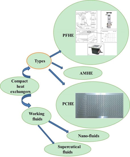
2. Main Types and Performance Optimization of Compact Heat Exchangers

This chapter reviews several main compact heat exchangers, summarizes and classifies their structure, flow and heat transfer characteristics, and discusses their material selection, pressure resistance, and operating parameters.

2.1. Plate-Fin Heat Exchanger (PFHE)

PFHE, with fins as heat transfer elements, has the advantage of high heat transfer efficiency. It is widely used in engineering machinery, power systems, medicine, the chemical industry and many other fields. According to the difference of the core unit structure, PFHEs can be divided into standard PFHEs, tube belt heat exchangers, and stacked heat exchangers. Metal fins of corrugated or other shapes are added between the two partitions, and the two sides are sealed with to form a closed channel, which constitutes the core unit of the standard PFHE. Then several core units are stacked in a certain order and fixed by brazing to form the core, and finally the core is welded with the head, flange and joints to form a complete standard PFHE. Thus, their light weight and small size are their main characteristics.
The fin is a key component that affects the flow and thermal performance of the PFHE. First, the disturbance of fins to the fluid causes the flow boundary layer to continue to rupture, thereby achieving enhanced flow and heat transfer. Secondly, most of the fins are made of aluminum alloy, which has high thermal conductivity and lighter weight. Finally, the PFHE has an additional expanded surface, which greatly increases its surface area density, which can generally reach 1000 m2/m3. The fins of the PFHE mainly include flat fins, wave fins, offset fins, louver fins, and perforated fins. Different types of fins have different applications [17]. At the same time, the PFHE has the problem of not being corrosion-resistant and is easy to be blocked, so it has requirements for the selection of fluid working medium and the locations in which it can be used.
The thickness of fins is a key parameter that affects the performance of PFHE. Kays [18] mentioned that when the fin thickness is increased from 0.006 inch to 0.01 inch, the pressure drop increases by 25%. Patankar and Prakash [19], through numerical solutions of the governing equations, found that increasing the thickness ratio greatly increased the pressure drop required when flow rate was a constant, but the heat transfer from thick plates was not sufficiently improved. Cur and Sparrow [20] studied the thermal hydraulic performance of collinear equal-spacing plates arranged parallel to the flat rectangular pipes. It is found that the existence of interruption is helpful to enhance heat transfer, and the fully developed flow related to thickness increases by as much as 65%. As in other studies [21], pressure drop increased with the increase of plate thickness. Research on effects of permeability and porosity of porous fins on friction and heat transfer rate gave the useful correlation between friction coefficient and modified j-factor in the design of porous PFHE. Yan and Sheen [22] tested plate-fins, wavy-fins and louver-fin heat exchangers under the condition of small Re, and showed that wavy-fin heat exchangers had the best area of goodness factor when Re was less than 1500. Choi et al. [23] found that for 7.5–15 mm fins of the discrete PFHE, the Colburn-j factor (j) is 6.0–11.6% higher than that of the continuous PFHE.
In addition to experimental tests, many scholars have also adopted the method of numerical simulation. Comparative studies on PFHE with different fin shapes have been done. Teat transfer rate of PFHE with elliptical tube fins was improved by 1.5–4.9% and pressure loss was reduced by 22.0–31.8% compared with large tube louver fins [24]. On the other hand, Colburn-j factors, Fanning friction factors (f) and thermal hydraulic performance of the wave-fins in a compact heat exchanger are lower than those of the louvered-fins compact heat exchanger under all research conditions [25]. Jeong et al. [26] proposed a new kind of louvered PFHE. Numerical simulation results show that crease angle is a key parameter, and the increase of crease angle will enlarge the influence of the crease cycle and hole number on the performance of the PFHE.
Heat transfer area, heat transfer coefficient and temperature difference are three important indicators that determine the thermal-hydraulic performance of PFHE. By summarizing the existing literature, it can be found that it is difficult to enlarge the heat transfer area of PFHE on the premise of keeping its structure compact, so it has become the research focus of many scholars to enhance the heat transfer by optimizing working fluid flow state. Jiao et al. [27] made experimental research on the flow distribution performance of PFHE, measured the distribution performance of inlet angles of different distributors, and studied the comprehensive influence of inlet angle and mass flow rate on flow distribution. Figure 1 shows the structure of PFHE in the experiments. Zhang et al. [28] found that the uneven distribution in two-phase flow is more obvious than that in single-phase flow, and it brought about a serious deterioration in heat transfer performance. By changing the header structure under the main test conditions, the fluidity and temperature unevenness of PFHE were reduced to 16.8% and 74.8%, respectively. Vortex generators have received widespread attention and are widely used to enhance heat transfer. Song et al. [29] conducted experimental research on curved delta-wing vortex generators (VGs) of different sizes. The smaller VG is located near the tube, which can improve the thermal performance of the flow with low Re, and the larger one is beneficial to improve the thermal performance of the flow with large Re. f is affected by the fin pitch, but j was hardly affected. Song and Tagawa [30] quantitatively studied the influence of the transverse distance of the vortex generators on the longitudinal vortex interaction and heat transfer performance.
Some scholars have written literature reviews on PFHEs. Therefore, this article will not go into too much detail. Only the research work of the past five years is summarized in Table 1 so that researchers can master the latest developments in the direction of PFHE.
Ordinary, PFHE rely on the tube bundle as a turbulence structure. When the fluid flows through the tube bundle and is disturbed, local acceleration areas will be formed on both sides of the tube, and downwardly developing horseshoe vortices will appear, thereby achieving local enhanced heat transfer. However, the wake area formed at the end of the tube will weaken the heat transfer. The study found that the use of elliptical tubes and the staggered arrangement has a better heat transfer effect than the use of round tubes and the traditional arrangement, and the pressure drop is also reduced.
Corrugated fins are prominent in increasing the heat transfer area. In addition, the periodic slight disturbance of the fluid caused by the corrugated fins along the corrugation direction can reduce the adverse effects of the boundary layer on heat transfer. The above two aspects make the thermal performance of corrugated fins much better than traditional plate fins, but the pressure drop caused by the corresponding corrugated fins will also increase a lot, which will increase pump power output. The wave angle is the key parameter of the wave fin. Under normal circumstances, the increase of the wave angle will enhance heat transfer, but research has found that the pressure drop increases significantly.
The heat transfer capacity of slits and louver fins is higher than that of corrugated fins [37], which also brings adverse effects, such as increased pressure drop and easy clogging problems. This is because the severe disturbance of the intermittent fins to the fluid can periodically provide boundary layer renewal. However, these disturbances will hinder the development of fluid flow, resulting in a drastic increase in pressure drop. In addition, the combination of different fins or the combination of fins and vortex generators will help to improve the performance of PFHEs and make them more widely used.

2.2. Printed Circuit Heat Exchanger (PCHE)

The manufacturing method of PCHE is completely different from PFHE. The basic module of PCHE is a piece of metal plate with flow channels obtained by a photochemical etching method. Then a plurality of etched metal plates is arranged and stacked in a certain manner, and bonded together through diffusion bonding under high temperature and high pressure to form the core of PCHE. In the diffusion bonding process, melting and melting-related defects are avoided, and the bonding pressure is much lower than the yield strength of the material, so the plastic deformation of the material is completely avoided. Diffusion bonding makes PCHE have excellent performance to withstand high temperature and high pressure, which makes its application range wider.
At present, PCHEs can be divided into two categories, namely PCHE with continuous flow channels and PCHEs with discontinuous flow channels. Among them, the main flow channel structure of PCHE with continuous flow channels include: straight channel, zigzag channel and wavy channel; the main flow channel structure of PCHE with discontinuous flow channels includes: S-shaped fin and airfoil fin. As the current application of the S-CO2 Brayton system is a hot research topic, the compact heat exchanger, which is very important to it, has also become a research hotspot. Among the types of compact heat exchangers, the PCHE has great potential, so this article discusses and summarizes the research progress of PCHE in detail.

2.2.1. PCHE with Straight Channels

Straight channel is the simplest channel type in PC HE, and it is also the basic form of channel configuration in PCHE. Because the flow of fluid in the direct channel will not be disturbed by the structure of the channel, PCHE with straight channel can obtain very low pressure drop, that is, the straight channel brings excellent hydraulic performance.
The design and development of PCHE cannot be separated from the experimental data of thermal and hydraulic performance related to PCHE. Under cooling conditions, experimental results show that the total heat removal effect is excellent near the pseudo-critical region [57]. The research of Baek et al. [58] showed that thermal performance of PCHE used in low temperature regions was mainly affected by axial conduction heat transfer in the low Re range. Complementing the work of Baek et al. [58], Mylavarapu et al. [59] studied the performance of PCHE under high temperature and high pressure by using the high-temperature helium test facility, and calculated j and Nu by numerical method for a wide range of working temperatures, pressures and flow rates. Chu et al. [60] studied the performance of PCHE under different working pressures of S-CO2. The experimental results show that PCHE has better comprehensive performance under higher pressure conditions. Park et al. [61] examined the characteristics of carbon dioxide in PCHE with straight channels based on three working conditions: trans-critical state (ante-critical state cooled from supercritical state to sub-cooled liquid), near-critical state (cooled from supercritical state of gas sample to supercritical state of liquid sample) and the far-critical state (cooled only in supercritical state of gas).
Compared with experimental methods, the numerical simulation method has many advantages, such as low cost, easy application of conditions, fast solution speed and enough data collection. Therefore, under the condition of insufficient experimental conditions, many scholars regard the numerical simulation method as the main research means. Yoon et al. [62] presented a code for analyzing thermal design and cost estimation of cross-flow PCHE. In the case of cooling, Xiang et al. [63] studied the convective heat transfer of S-CO2 in horizontal tubes and found that heat flux had a serious influence on its position. Zhang et al. [64] found that local heat transfer deteriorated under the condition of low mass flux or high heat flux. This is because the buoyancy effect changes the distribution of cross-sectional parameters and enhances the secondary flow. When the influence of buoyancy is neglected, the distribution of specific heat of fluid dominates the heat transfer characteristics.
Correlation is an important aspect to study the thermal-hydraulic performance of PCHE, which has been studied by many scholars by numerical simulation or experiment. By calculating and analyzing the data results, some relevant correlations are obtained, which is beneficial to the subsequent development of PCHE. Kim et al. [65] studied the hydraulic characteristics of PCHE in the lower range of Re (Re < 150) by numerical method, and verified the simulation values by experimental data. Finally, the numerical correlation of j was given. Li et al. [66] proposed a correlation to evaluate the forced convective heat transfer of S-CO2 by probability density function (PDF)-based time-averaged properties. Since extensive numerical research, Kim et al. [67] provided a mathematical expression to predict the thermal performance of crossed, parallel and countercurrent PCHE. Liu et al. [68] deduced the heat conduction equation of straight channel PCHE fin by numerical calculation, obtained the longitudinal temperature distribution of fin, and established the expressions of fin efficiency. Based on simulation and experimental results, Zhang et al. [69] developed new heat transfer correlations for S-CO2 cooling, and both correlations included buoyancy and tube inner diameter. Zhao et al. [70] presented the average Nu and f of supercritical nitrogen in PCHE single channels by using numerical data, and both predicted well. By implementing the characteristic correction technology based on PDF, Li et al. [71] presented a semi-empirical correlation of physical improvement of S-CO2 forced convection heat transfer, which can explain the influence of instantaneous turbulent temperature and fluctuation characteristics. Flow distribution has a great influence on performance of PCHE. Chu et al. [72] put forward the correlation between thermal and hydraulic performance of straight channel PC HE and flow nonuniformity correction. Ren et al. [73] developed a correlation considering buoyancy effect and the change of thermophysical properties.
At present, PCHE is a potential choice for the intermediate heat exchanger of the new generation of nuclear reactor cooling systems [15]. The steady-state thermal performance of PCHEs may have a great impact on the main cooling system, so it is the research direction of many scholars to understand how PCHE responds dynamically to various transients of operating conditions of PCHE. By analyzing the data obtained from experimental measurement and numerical simulation, a kind of applicability of dynamic model can be used to predict the steady-state and transient performance of straight channel PCHE, which was provided by Chen et al. [74], but the difference of helium outlet temperature between numerical solution and experimental data caused by heat loss of the heat exchanger was not considered in the model. Marchionni et al. [75] embedded PCHE models into the model of complete S-CO2 power units for numerical simulation. The results of dynamic simulation showed that the thermal expansion of S-CO2 caused by the rapid decrease of density and the increase of system pressure will lead to sudden changes in temperature and thermal stress, which may have adverse effects on system operation.
The initial conditions faced by heat exchangers in different working environments are different, such as heat flux and inlet temperature, which will affect the performance of PCHE, and many researchers have conducted relevant research. Li et al. [66] calculated and analyzed the simulation results under different heat flows and found that high heat flow significantly inhibited the heat transfer efficiency in heating mode, but had little effect in cooling mode. In addition, Li et al. [71] got the same conclusion as before in another study of forced convection heat transfer in PCHE. The experimental and simulation results of S-CO2 cooling flow in tubes by Zhang et al. [69] showed that pressure, mass flux and inner diameter have different degrees of effects on the heat transfer characteristics of S-CO2 and pressure drop during cooling. Meshram et al. [76] numerically analyzed the state of S-CO2 in a straight channel under the condition of complete turbulence, and compared this with the zigzag channel. Chai and Tassou [77] established a three-dimensional numerical model considering the inlet effect, conjugate heat transfer effect, thermophysical properties of NIST real gas, and the buoyancy effect. It was found that the inlet effect would cause the local heat transfer to drop rapidly near the inlet and then keep stable along the flow direction, and the pressure gradient was positively correlated with the temperature of S-CO2. Based on the influence of different boundary conditions on the dynamic response characteristics and equilibrium time of thermodynamic parameters on PCHE, Ma et al. [78] predicted the performance of PCHE through a neural network, which is very helpful for further constructing the dynamic model of the whole S-CO2 power system.
Sharing the same goal as Ma et al. [78], Kwon et al. [79] developed PCHE off-design quasi-steady-state performance models for regenerator and precooler in a S-CO2 Brayton cycle to optimize the operation strategy of power system under off-design conditions.
The structural parameters of the channel are important to characterize PCHE characteristics. Jeon et al. [80] analyzed the influence of channel size, channel spacing and channel cross-section shape of heat source fluid and heat dissipation fluid on thermal performance through numerical study. The thermal performance of PCHE decreased proportionally with increasing the size of channels while remaining mass flow rate as a constant. In addition, under the condition of constant hydraulic diameter, the adjacent distance and cross-sectional shape of channels have little influence on the performance of PCHE. Aneesh et al. [81] found that the staggered arrangement of cold and hot channels in PCHE showed almost the same performance. Moreover, compared with double-banking, single-banking performs better. Cross-section shape is an important feature of the straight channel, which has certain influence on the flow development of fluid in the channel. The numerical simulation results of Figley et al. [82] showed that semicircular channels had a higher critical Re of transition flow compared with circular channels. Tu and Zeng [83] made a comparative study on characteristics of two types of channels. The results showed that, under the same hydraulic diameter, although circular channels had a higher convective heat transfer coefficient, semicircular channels had a larger heat transfer area, making the comprehensive heat transfer capacity of semicircular channels stronger. Moreover, when the inlet velocity of the semicircular channel is constant, pressure drop and heat flux are negatively correlated. In addition to the common semi-circular and circular channels, some scholars have also tried to explore the f characteristics of S-CO2 in channels with other cross-sectional shapes, in order to find the best cross-sectional shape of channels under different working conditions. Cao et al. [84] found that the length-width ratio of triangular tubes and the pointing direction of triangular apex angle have important influence on fluid flow and heat transfer. Khalesi et al. [85] conducted research on conjugate heat transfer and fluid flow of S-CO2 in rectangular microchannel. The structure and configuration of channels are the basis of PCHE research and design, and have an important impact on the comprehensive performance of PCHE. Although the channel spacing has little effect on the heat transfer capacity, the channel spacing will significantly affect the structural reliability of PCHE. Cross-sectional shape affects the flow development of fluid and has a strong inlet effect.
Because the influence of gravity always exists in the actual operating environment of the heat exchanger, the buoyancy effect caused by gravity must be considered to affect the performance of PCHE. A study on laminar mixed convection heat transfer of S-CO2 in horizontal microtubes showed that buoyancy significantly enhanced heat transfer in thermal imbalance, especially near the false critical point [84]. Xiang et al. [63] conducted similar numerical simulation, and it showed that temperature was stratified and the secondary flow was produced. In addition, the buoyancy effect led to asymmetric distribution of radial velocity and turbulence kinetic energy on cross-section, and buoyancy effect became more significant as heat flux and pipe diameter increased. Zhang et al. [86], based on the study of coupling heat transfer characteristics of S-CO2 in horizontal semicircular channels, made a further supplement to the related work of previous scholars. It showed that the buoyancy effect is negatively correlated with mass flow rate, and asymmetric flow performed better than symmetric flow on heat transfer at low mass flow rate. Buoyancy can enhance the heat transfer to the top wall of the hot side, but it will lead to the deterioration of the thermal performance of the bottom wall, while the opposite is true on the cold side.
Surface interruption is often used as a heat transfer enhancement technology because it can interrupt the development of flow to enhance the mixing of fluids and periodically destroy the boundary layer. Therefore, adding turbulence structure in the channel is an important direction to optimize the performance of PCHE with straight channels. Aneesh et al. [81] found through numerical simulation that thermal performance of straight channels with different numbers of hemispherical pits equidistantly distributed along the channel length was enhanced, but pressure loss was also increased. Inspired by this work, researchers can further optimize the structure of the straight channel by changing the shape, size and arrangement of the insertion structure in order to obtain better thermal performance and lower pressure loss.
Researchers pay more attention to heat transfer of the core structure of PCHE, but the increase of pressure loss caused by uneven flow rate will seriously reduce the comprehensive performance of PCHE and make the heat exchanger deviate from the stable working state, resulting in low working efficiency. The inlet manifold of PCHE has an important influence on the flow distribution, so a few scholars have started to study and optimize the design of PCHE inlet manifold. Chu et al. [72], based on streamline, put forward a new and improved hyperbolic inlet, which can greatly improve the uneven flow distribution and the overall performance of PCHE. In addition, the flow nonuniformity can be minimized by changing the core length.

2.2.2. PCHE with Zigzag Channels

Compared with PCHE with discontinuous fins, PCHE with straight channel and zigzag channels is simpler in chemical etching of flow channels and has higher structural strength after being assembled into core by diffusion bonding. At present, many researchers are working to explore and optimize the performance of PCHE with zigzag flow channels.
The research and development of heat exchangers it is being applied to engineering practice to obtain higher energy efficiency conversion. Because the specific working conditions of heat exchangers are different in engineering practice, it is basic and necessary to conduct experimental and numerical studies on the performance of PCHEs under different working conditions. Based on the conditions of different inlet temperatures, pressures and mass flow rates, Nikitin et al. [87] made an experimental study by using the S-CO2 loop, and presented an empirical correlation formula for predicting the coefficients of local heat transfer and pressure drop changed with Re. Similar to the work of Nikitin et al. [87], in the helium laminar flow range of 350 < Re < 1200, Kim et al. [88] used the KAIST helium test loop to conduct experimental research on PCHE under different inlet conditions, and proposed a global f correlation and a global Nu correlation. At the same time, they also carried out a 3D numerical simulation which is in good agreement with the experimental data, and presented a local pitch-averaged Nu correlation. Furthermore, through the system analysis code, it showed that the correlation proposed is more suitable for system analysis. Kim et al. [89] put forward a new auxiliary correlation of CFD by comparing the correlation between CFD results and experimental results, which covers the extended range of Re from 2000 to 58,000. Bennett and Chen [90] introduced in detail the development and evaluation of the correlation for Nu and f in cold and hot channels, and these correlations considered the geometry and inlet parameters of PCHE with zigzag channels.
Due to the limitation of experimental conditions and other factors, there is basically no large-scale experimental study on PCHE as a precooler of the S-CO2 Brayton cycle. Cheng et al. [91] used a 100-kW class PCHE applied in S-CO2 Brayton cycle, and investigated the effects of inlet Re and inlet temperature on thermal-hydraulic characteristics and effectiveness of heat exchangers by experimental method. It is found that increasing the inlet temperature of water can reduce the pressure loss, but it will adversely affect the heat transfer performance and effectiveness. In addition, higher effectiveness can be achieved by increasing the inlet Re of water or decreasing the inlet Re of S-CO2.
Ma et al. [92] found through numerical simulation that the fluid flow and temperature in PCHE could not reach the full development state at high temperature, but the dimensionless velocity and temperature would be stable after the second pitch, which is similar to the fluid flow behavior at low temperature. On the basis of experimental data, Chen et al. [93] established the correlation between pressure drop and heat transfer in zigzag channels with rounded bends. Compared with the thermal performance of straight circular pipes, zigzag channels have obvious advantages in transitional flow. Chen et al. [94], through the analysis of local hydrothermal properties, found that the fully developed flow conditions were not observed in PCHE due to the periodic flow disturbance at each bend of zigzag channel, and found that the local and global heat transfer coefficients of PCHE were quite different. In addition, the fluid temperature and heat flux are not uniform along the direction of the flow channel, and the temperature distribution along the flow direction presents a wavy profile.
The accuracy of the assumptions of CFD numerical models is the key to the reliability of numerical simulation results, because it is the decisive factor of the consistency between numerical simulation results and experimental real data. Kim and No [95] respectively studied the horizontal and vertical arrangement of PCHE by KAIST helium-water test loop and numerical simulation. Only the numerical pressure drop data of vertical operation is in good agreement with that of the experiment. Finally, according to the tested PCHE, the f correlation and the Nu correlation are proposed. Yoon et al. [96] did related work on the development and verification of Nu and f for laminar flow of PCHE with semi-circular zigzag channels. Chen et al. [97] simulated and analyzed the dynamic behavior of PCHE in zigzag channels affected by the change of helium inlet temperature and helium mass flow rate steps, and verified the feasibility of predicting steady-state and transient performance of PCHE by the dynamic model through experiments.
Like the straight channel, the structure of heat exchangers including channel cross-sectional shapes and configuration will disturb the flow of working medium to some extent, thus affecting the performance of PCHEs with zigzag channels to varying degrees. According to multifarious channel cross-sectional shapes and channel configurations, Lee and Kim [98] made a comparative study on the performance of PCHEs with zigzag channels and found that the effectiveness and friction coefficient of PCHEs are positively correlated with the heat transfer area of the channel. In the same way, through the comparison and analysis of the simulation results, the scheme with the strongest heat transfer performance and the scheme with the lowest pressure drop are obtained respectively among the four proposed flow channel configurations. In another study, Lee and Kim [99] also analyzed the influence of geometric parameters on the performance of PCHE. It was found that the effectiveness of PCHE was maximized at about 110° cold channel angle, but the nondimensional pressure drop decreased with this angle monotonously. Kim and Sun [100] considered PCHE schemes with various bank configurations for the secondary heat exchanger using FLiNaK-helium as working fluid. Saeed and Kim [101] evaluated the performance of PCHE with various Re and different geometric configurations by using the optimization field. The results show that the serrated structure of PCHE is sensitive enough, which will have an important impact on the performance parameters when a wide range of Re is used. Therefore, the existing correlation is not suitable for use in an extended range, and it is necessary to establish different correlation combinations in different Reynolds number. Zhang et al. [102] studied the influence of bending angle on characteristics in zigzag channels, and analyzed and discussed it by using entropy generation and field synergy principle. Numerical simulation results showed that, within a certain angle range, the heat transfer performance increased with the increase of bending angle, but the resulting pressure loss also increased. In addition, reverse flow and secondary flow also significantly influenced the local performance of serrated channels.
In addition to the basic research on PCHE with zigzag channels, such as the influence of inlet conditions, channel structure and arrangement and other factors on characteristics of heat exchangers, it is also an important work to optimize PCHE to obtain better thermal and hydraulic performance. Lee and Kim [103] optimized the cold channel angle and elliptical aspect ratio of PCHE with zigzag channels by using the RSA surrogate model and genetic algorithm. Jiang et al. [104] designed and simulated PCHE with zigzag channels for high-temperature and low-temperature regenerator of Brayton cycle plants with 100kWe S-CO2 recompression, and verified these two models by comparing them with experimental data of small exchangers used in 100kWe equipment. Finally, the optimized design results show that the metal mass of each cold plate with two hot plates and high angle channels is smaller, which is a better choice for large-scale applications.
For the zigzag channel, there is a great pressure drop because of the influence of flow separation and reverse flow at the bend point, that is, its hydraulic performance is very poor. Lee et al. [105] presented a zigzag-type PCHE with inserted straight channels, aiming at the great influence of bending point on pressure drop in zigzag channels. Through numerical simulation, it was found that pressure drop decreased when the straight channels with lengths of 0.5 mm and 1 mm were inserted, and the heat transfer performance of the new channel did not decrease compared with that of the zigzag channel. It means that inserting a straight channel into the zigzag channel can weaken the flow separation and reverse flow at the bending point, thus greatly improving the hydraulic performance of PCHE without reducing its thermal performance. This work provides a good research idea for optimizing the performance of PCHE with zigzag channels.
Different from Lee et al.’ s scheme of inserting straight channels into PCHE with zigzag channels [105], Ma et al. [106] proposed an improved double-sided etched zigzag PCHE design based on slots on ellipse, and carried out numerical simulation on the scheme. The simulation results show that, compared with the original zigzag channel with semi-elliptical cross section, the heat transfer capacity of the new channel will increase in different degrees according to the increased height of the slot on the ellipse, but the corresponding pressure loss will also increase.
There are many researches on PCHE with zigzag flow channel. Besides the above, some articles have studied such aspects as evaluation method and sensitivity analysis. Li et al. [107] estimated the overall heat transfer performance using an evaluation method of operating point, which considered the influence of operating temperature and pressure. Bennett and Chen [108] carried out a sensitivity analysis for main and two factor interaction. The simulation data showed that the hydrothermal performance parameters of PCHE with zigzag channels were most sensitive to the changes of the channel bending angle, bending angle curvature radius, mass flow rate and channel width. In addition, Bennett and Chen [109] conducted a fluid–structure interaction (FSI) evaluation on PCHE with zigzag channels by using finite element analysis (FEA).

2.2.3. PCHE with Wavy Channels

PCHE with wavy channels can be regarded as an improved version of PCHE with zigzag channels based on the requirement of low pressure drop. Compared with zigzag channel, the flow disturbance caused by wavy channels at the bend is smaller, so the pressure drop of wavy channel is lower, but its heat transfer capacity is also decreased. Combined with experimental data and calculation analysis, Baik et al. [110] found that compared with the common zigzag channels, the realistic rounded channels can reduce the pressure drop by 40–65%. In addition, two sets of friction coefficient and heat transfer correlation are developed for laminar flow on the water side and turbulent flow on the carbon dioxide side. In another study conducted by Baik et al. [111], it showed that the thermal performance of PCHE with wavy channels was improved by 16.4% compared to PCHE with straight channels. Based on certain operating conditions, Khan et al. [112] found that PCHE with wavy channels has better thermal performance than PCHE with straight channels. And when the bending angle of the wave-shaped channel is 5°, 10° and 15° and Re range is 350 < Re < 2100, the correlation between the f and the Re and the correlation between the Nu and Re are respectively proposed.
The scope of application of PCHE with wavy channels of different designs is different. Through experiments and numerical studies, Sung and Lee [113] found that the tested PCHE showed enhanced heat transfer when Re was in the range of 1000 to 3000. Furthermore, the heat transfer improvement of the mixing zone in the low Re range is explained by using the concept of temperature uniformity.
Waviness factors are important parameters of a wave-shaped flow channel. Baik et al. [111] studied the influence of waviness factors, including amplitude and period, on PCHE. It showed that the thermal performance of PCHE with wavy channels increased proportionally with the increase in amplitude or period. It needs to be pointed out that for each unit cycle, its thermal performance will increase with the increase of the amplitude, but will decrease with the increase of the cycle. Yang et al. [114] found that the heat flux distribution on the surface of wavy channel changes periodically through numerical simulation. In each cycle, there is a low heat conduction band area on the arch surface and two low heat conduction band areas on the bottom surface. Finally, according to the fluid parameters of each cycle in wavy channel, a new empirical correlation between heat transfer coefficient and friction coefficient is proposed, and the prediction error of the heat transfer correlation to Nu in PCHE is 10%. The research conducted by Wang et al. [115] showed that, compared with straight channels, the enhancement of heat transfer capacity of sinusoidal channels was not caused by the increase of heat transfer area, but by the enhancement of local turbulence intensity of working fluid near the corner. In addition, when the working conditions match the design of PCHE, the thermal and hydraulic performance of PCHE will be fully reflected. With the increase of the ratio of amplitude to period, the Nu and Fan Ning friction coefficient in sinusoidal channels both increase at first and then decrease.
Cui et al. [116] conducted numerical research on six cross-sectional flow channels. The circular cross-sectional channel provided the highest thermal performance, while the vertical elliptical cross-sectional channel had the smallest flow friction. In addition, a high Prandtl number (Pr) can significantly improve the thermal performance near the pseudo-critical point, and the generated secondary flow can enhance the convective heat transfer in the wavy channel by improving the field synergy.
In addition to focusing on the influence of the properties of wavy channels on the performance of PCHE, some researchers explored the advantages and disadvantages of wavy channels by comparing PCHE with different channel types. Aneesh et al. [117] compared characteristics of zigzag channels, wavy channels and zigzag channels inserted into straight channels by numerical simulation. Under the same operating conditions, compared with straight channels, zigzag channels inserted into straight channels provided the highest thermal performance and pressure loss penalty, while wavy channels provided the lowest pressure drop penalty although the heat transfer enhancement was not as good as zigzag channels and zigzag channels inserted into the straight channel. By comparison, it found that the performance balance of PCHE with wavy channels is more prominent.

2.2.4. PCHE with S-Shaped Fin Channels

The s-shaped fin is a common fin type in PCHEs with a discontinuous flow channel. It is generally believed that the S-shaped fin evolved from a sinusoidal channel, aiming at eliminating the reverse flow in sinusoidal channel and reducing the low momentum basin at the end of channel.
Ngo et al. [118] first put forward the scheme of PCHE with an S-shaped fin channel, and studied its thermal and hydraulic energy through experiments and numerical simulation methods. The results showed that compared with the heat exchanger used by a hot water supplier, the new PCHE provided 3.3 times smaller volume, 37% smaller pressure loss on the carbon dioxide side and 10 times smaller pressure loss on the water side. Saeed and Kim [119] used response surface method and genetic algorithm to optimize the geometry of S-shaped fin, and according to the numerical calculation results, proposed the correlation between heat transfer and pressure drop of optimized channel. Moreover, the pressure drop of the optimized S-shaped fin runner is 2.4 times smaller than that of the traditional zigzag runner and shows better thermal hydraulic performance in the low Re range.
Tsuzuki et al. [120] obtained the best channel configuration considering the comprehensive performance of PCHE by changing the structure and angle of the S-shaped fin. Under the condition of the same thermal performance, the pressure drop of PCHE with the best flow channel configuration is one fifth of that of PCHE with a zigzag flow channel, because the flow distribution of working fluid in the new flow channel is more uniform, and the reverse flow and vortex at the bend in zigzag flow channel are eliminated. Later, Tsuzuki et al. [121] made a more detailed study on the influence of structural parameters of S-shaped fins on PCHE in another work. Through numerical simulation, it is found that the wing angle is the most sensitive parameter of PCHE’s thermal and hydraulic performance, and the roundness of fins at the head and tail edges has the least influence on heat transfer performance, but has a great influence on pressure drop performance. In addition, considering the heat transfer performance, pressure loss and structural strength, the optimal guide wing, fin width and fin length were selected.

2.2.5. PCHE with Airfoil Fin Channels

Airfoil fin is another common fin type of PCHE with discontinuous channels, which was first proposed by Kim [122]. This discontinuous fin is symmetrical in geometry, so it is called airfoil fin because its shape is similar to a wing. In the working process, fluid flows into PCHE along the head direction of the airfoil fin, heat exchange occurs between the fin and the wall surface, and then flows out from the tail direction of the airfoil fin. Cold-side fluid and hot-side fluid basically adopt countercurrent mode to obtain better overall heat transfer performance.
The geometric parameters of airfoil fins are shown in Figure 2. Geometric parameters of airfoil fins include height, width and length. Xu et al. [123] found that staggered airfoil fins can obtain better hydrothermal performance, and the flow resistance is the key to determining overall performance. A new type of fin structure, the diamond fin, is proposed. The new type of fin is superior to the traditional airfoil fin in hydraulic performance. When S-CO2 is used as the working fluid, the first consideration is to reduce the pressure drop, so the airfoil fins should be arranged in sparse arrangement. Furthermore, the rhombic fins are suitable for reducing the flow resistance, thereby reducing pressure drop.
The main geometric parameters affecting the performance of PCHE with airfoil fins are horizontal, vertical and staggered pitch. The geometric parameters of airfoil fins arrangement are shown in Figure 3. Kim et al. [124] used a numerical simulation method to study the influence of airfoil fins arrangement on the performance of PCHE. The staggered arrangement of airfoil fins hardly affects thermal performance, but significantly affects pressure loss. When the staggered number ξ s = 2 L s / L h = 1 , it is the optimal arrangement considering comprehensive performance. The increase of horizontal distance will improve hydraulic performance, but it also has obvious negative influence on heat transfer performance. Compared with the influence of horizontal distance, the increase of vertical distance also brought lower pressure drop, but had little effect on heat transfer. Ma et al. [125] reached the same conclusion as Kim et al. [124] through experiment and numerical simulation. It was also found that the fillet of fin-end wall would produce small vortex at the leading edge and trailing edge of inclined surface, which led to the increase of heat transfer and pressure drop. Based on the transverse distance and staggered longitudinal distance, the local and global heat transfer and flow characteristics are analyzed. It is found that the strong change of thermophysical properties of S-CO2 leads to the gradual decrease of local thermal performance along the flow direction, but the local flow resistance is basically unchanged. Chu et al. [126], based on the data of numerical simulation, put forward the fitting correlation of j and f with Re (8000 < Re < 100,000). The results show that large windward area and short length can obtain better thermal-hydraulic performance.
Compared with the traditional PCHE with zigzag channel, the numerical simulation results show that the pressure loss of NACA 0020 airfoil fin PCHE is significantly reduced, while maintaining good thermal performance. Besides, when the vertical pitch is a constant, the increase of heat transfer capacity is far less than the increase of pressure drop [127]. Cui et al. [128] proposed two new airfoil fins. One of the airfoil fins showed the best comprehensive performance at low Re; the other provided the lowest pressure drop. The staggered arrangement and proper shape of airfoil fins can periodically destroy the fluid flow boundary and improve the heat transfer effect.
Because of the difficulty in manufacturing and the difficulty in collecting experimental data, there are few experimental studies on PCHE with airfoil fins. Based on the experimental conditions from near critical point to gas sample area, Pidaparti et al. [129] studied the characteristics of discontinuous offset rectangle and NACA 0020 airfoil fin PCHE, and put forward the empirical correlation between Nu and f.
In recent years, some researchers have carried out the research on the airfoil fin PCHE with molten salt as the convection medium. Fu et al. [130] proposed a PCHE with S-CO2 airfoil channel and molten salt straight channel and simulated it. Compared with parallel arrangement, staggered arrangement has shorter pressure and temperature periods and smaller fluctuation, and the overall heat transfer coefficient and pressure loss of airfoil fin PCHE will be lower. Unlike that channel allocation proposed by Fu et al. [130], Wang et al. [131] used molten salt and a synthetic oil as working fluids in airfoil channels and straight channels of PCHE respectively. According to the experimental results, two heat transfer correlations are proposed. Shi et al. [132] found that higher inlet temperature can improve the thermal performance of molten salt, but has no significant effect on the thermal performance of S-CO2, and it also can reduce the flow resistance of two working fluids. Furthermore, the correlation between heat transfer coefficient and pressure drop coefficient in PCHE airfoil channel was proposed, which is suitable for large Re number and temperature range.
In addition to studying the performance of PCHE with airfoil fins, some scholars have optimized the design of heat exchangers based on specific objective functions. Kwon et al. [133] presented a method to predict the correlation between Nu and f. Then, based on the cost objective function including the production cost and operation cost of the heat exchanger, the allocation of airfoil fins in PCHE is evaluated by using the total cost, and the optimal allocation of airfoil fins is proposed. As far as the existing published literature is concerned, there are relatively few numerical and experimental studies on PCHE with airfoil fins. Further research work is needed to optimize the design of PCHE with airfoil fins and improve the correlation between heat transfer and pressure drop.

2.3. Additive Manufacturing Heat Exchanger (AMHX)

Additive manufacturing, which can also be called 3-D printing in general, comes from the technology of manufacturing three-dimensional objects by continuously adding layer upon layer of materials. In this process, raw materials exist in the form of powder, and material layers are deposited on the substrate or base material to form a geometric shape in the vertical direction through the continuous layers. Compared with the traditional manufacturing technology, additive manufacturing has shown obvious advantages, and has been tried to manufacture heat exchangers with various structures. First of all, additive manufacturing can realize complex and novel design, but it is difficult or impossible to process this complex geometric shape with traditional manufacturing technology. If traditional manufacturing technology is adopted, it may bring high cost restrictions related to factors such as mold and time. Secondly, the compact heat exchanger manufactured by using the additive does not need to be welded and brazed at the joints between various components, so the integrity of the heat exchanger manufactured by the additive is very good. Thirdly, the raw materials used in additive manufacturing exist in the form of powder, so it will not be limited by the application of materials. Finally, modular design brings good operability to additive manufacturing. Although additive manufacturing has many advantages and can process various complex heat exchanger structures which were difficult to realize before, the thermal hydraulic performance and structural strength of AMHX formed by processing may be adversely affected by surface roughness, geometric deviation and potential defects [134]. In view of the advantages and disadvantages of AMHX and the thermal hydraulic performance of various heat exchangers with complex structures, many scholars have conducted experimental research and exploration.
Comparing the thermal performance and hydraulic performance of stamped aluminum aircraft oil cooler manufactured by traditional manufacturing technology with three geometrically equivalent counterparts manufactured by additive manufacturing technology, Bichnevicius et al. [134] found that AMHX showed obviously higher air side pressure drop and higher thermal performance compared with the heat exchanger manufactured by traditional manufacturing technology. In addition, due to the influence of surface roughness, geometric deviation and potential defects, the performance of the three AMHX is also different. Therefore, it is necessary to verify the design, manufacture and structural integrity of AMHX [135]. Saltzman et al. [136] also made similar comparison verification through experiments. Based on the data results, the total heat transfer of AMHX and enhanced AMHX heat exchanger increased by about 10% and 14% respectively, but the air side pressure drop of AMHX was twice as high as that of the heat exchanger manufactured by tradition. Based on a high-power density thermal energy storage using heat exchangers made of additives, Moon et al. [137] used simulations and experiments to explore the role of internal and external fins in enhancing heat transfer from liquid coolant to phase change materials. Searle et al. [138] proposed a heat exchanger with pin fins with helical arrangement manufactured by additive manufacturing technology, which showed good thermal performance in experimental test, in which the pin arrangement was helical to promote heat transfer caused by eddy current. In addition, the metal porous crystal heat exchanger proposed by Ho et al. [139] has a good performance in enhancing heat transfer on the air side, and the heat exchanger is also manufactured by additive manufacturing technology. Zhang et al. [140] used the conceptual model of approximation assisted optimization heat exchanger to optimize the design, and verified the optimization results through the heat exchanger manufactured by additive manufacturing technology.
A pyramid-shaped pin-fin heat exchanger was proposed and then it was manufactured by additive manufacturing technology. Based on forced convection conditions, Cormier et al. [141] explored the influence of fin height and fin density on the thermal-hydraulic performance of tapered pin fins. Increasing the fin height or fin density will increase the overall heat transfer performance and also bring higher pressure loss. By calculating and analyzing the data, it is proposed to predict the correlation between the heat transfer performance and geometric shape of pyramid-shaped pin fins. Kirsch and Thole [142] made four pin fin arrays with different spacing, and tested their pressure loss and heat transfer performance in a certain Re range. Experimental results show that, compared with the smooth pin-fin array in literature, the high surface roughness of the tested pin-fin array has a greater influence on the increase of pressure drop than on the increase of heat transfer.
In addition to low manufacturing cost and low weight, compact polymer heat exchangers can also provide good anti-corrosion and anti-fouling performance, so it has attracted the attention of some researchers. Arie et al. [143] manufactured a new type of polymer heat exchanger with additives and made an experimental study. The results showed that the thermal and hydraulic properties of the tested polymer heat exchanger were better than those of the commercial plate fin heat exchanger.
Additive manufacturing can not only process the whole heat exchanger, but also be used in the manufacture of heat exchanger components. Therefore, the research on AMHX cannot be limited to the whole heat exchanger, and the effect of components made of additives on the performance of heat exchangers is also an important research content. Tiwari et al. [144] explored the effect of more accurate flow distribution of single-phase flow in tubular manifold microchannel heat exchanger through experiments.
In the absence of experimental conditions, numerical simulation can also be used as the main way to study and evaluate the manufacturing of heat exchangers with additives. Greiciunas et al. [145] put forward a conceptual heat exchanger design manufactured by additive manufacturing technology and evaluated it numerically. Based on laminar flow conditions (500 < Re < 2000), some scholars have carried out numerical simulation on different types of finned tubes which can be manufactured by additive, and evaluated the overall performance of heat transfer enhancement and pressure loss of finned tubes by entropy production [146].

3. Types of Fluid Working Medium in Compact Heat Exchanger

At present, the enhancement of heat transfer by optimizing the structure of heat exchanger has a new set of challenges, so researchers pay attention to the fluid working medium. This chapter will summarize and analyze the commonly used and potential fluid refrigerants in compact heat exchangers and put forward some suggestions for their development.

3.1. Nanofluid

With the development of nano-material technology, researchers have gradually applied it to the field of heat transfer and developed a new type of fluid working medium in order to enhance heat transfer. Choi [147] put forward the concept of “nanofluid” for the first time and used it to describe the liquid suspension containing nano-sized particles. In recent years, the research literature on nanofluids has increased rapidly, which shows the importance and great potential of nanofluids in heat transfer enhancement. Because the flow channel size of compact heat exchangers is very small, and the stability of nano-fluid prepared at present is not good enough (which may form aggregates with larger particle size to block the flow channel), there are few cases of applying nano-fluid to compact heat exchanger, which can be said to be basically in the experimental research stage. Hosseini et al. [148] divided the particles ranging from 1 μm to 4 mm into six groups according to their size and carried out experimental research on particle deposition of compact heat exchangers at the flow rate of 1 m/s to 5 m/s, and carried out numerical simulation on particles ranging from 1 μm to 100 μm in diameter. First, most particles are deposited in front of the compact heat exchanger and at the edges of both ends of the fin channel. Secondly, increasing the number of particles will lead to greater pressure loss, but deposition will increase to a critical dimension, and then it will decrease. Finally, the deposition of small particles will increase with the increase of flow rate, but the deposition of larger particles is the opposite.
The application of Al2O3–H2O nanofluids in compact heat exchangers has become a hot research topic. The effect of Al2O3-H2O nanofluids on heat transfer performance of rectangular nanotube radiators under different volume fractions (0.10–0.25%) and low Re range (395 < Re < 989) has been studied [149]. The experimental results show that using nanofluids instead of pure distilled water can improve the thermal performance, and the maximum heat transfer coefficient is increased by 18%. Through two-dimensional numerical simulation, Khoshvaght-Aliabadi [150] analyzed the heat transfer and flow characteristics Al2O3–H2O nanofluid in sinusoidal channels under different Re (6000 < Re < 22,000) and different nanoparticle volume fractions (0–4%). The results show that, compared with the base fluid, the nanofluid has a higher value of Nu, while the values of f of both fluids are close, which means that using the tested nanofluid instead of water as the fluid working medium of the heat exchanger can achieve higher heat transfer performance without bringing greater pressure drop penalty. Finally, the correlation between Nu and f for predicting the flow of Al2O3-H2O nanofluids in sinusoidal channels is proposed. Ray et al. [151] obtained the preliminary correlation between Nu and friction coefficient of nanofluid flow in compact miniature tube-plate heat exchanger through the experiment of 0.5 vol.% Al2O3 nanofluid. In addition to the research on Al2O3-H2O nanofluids in the above-mentioned compact heat exchanger, other scholars have studied the characteristics of nanofluids in PCHE [152,153] and compact heat exchangers with spears and offset fins [154] and obtained some similar conclusions. These works laid a foundation for further research of Al2O3-H2O nanofluids used in compact heat exchanger.
Stogiannis et al. [155] proposed a miniature plate heat exchanger (PHE) with modulated surface, whose fluid working medium is SiO2-H2O nanofluid with a volume fraction of 1%. Experiments show that compared with water, it can increase the heat transfer rate by 35%. In addition, the numerical simulation results show that when the SiO2-H2O nanofluid with a volume fraction of 1% is used as the working fluid instead of water at a given working temperature, less cooling liquid is needed, so the pumping power can be reduced. Based on the numerical simulation of SiO2-H2O nanofluid with a volume fraction of 8% in a house-shaped corrugated channel, Ajeel et al. [156] established a new correlation between the Nu and friction coefficient. Khanlari et al. [157] studied the characteristics of TiO2-H2O nanofluid in compact plate heat exchangers, in which the volume fraction of TiO2-H2O nanofluid was 2%. In order to prevent precipitation and flocculation, surfactant (Triton X-100) was added into the nanofluid. The results of numerical simulation show that the overall heat transfer coefficient of TiO2-H2O nanofluid is increased by 6% on average. In the forced convection heat transfer experiment, the heat transfer rate of the double-tube counter-current heat exchanger with internal longitudinal fins is 80–90% higher than that of the ordinary flat tube heat exchanger with 0–4 Vol.% Fe3O4-H2O nanofluid [158]. Furthermore, there are several studies on other types of nanofluids, such as ZnO-H2O nanofluids [159] and Ag-H2O nanofluids [160] in a compact heat exchanger.
In addition to studying the flow and heat transfer characteristics of a single kind of nanofluid in compact heat exchangers, the performance comparison between different types of nanofluids is also an important research direction. The mixture of ethylene glycol and water was used as basic fluid, and Al2O3, CuO and SiO2 nanoparticles were added into it to form three kinds of nanofluids. Ray et al. [150] theoretically studied the characteristics of these three nanofluids in compact microchannel plate heat exchangers (PHE). The results show that when the volume fraction of nanofluids is 1%, the flow and heat transfer performance of above three nanofluids is better than that of the basic fluid. The thermal conductivity and viscosity of ZnO nanofluids and TiO2 nanofluids based on the mixture of ethylene glycol and water are positively correlated with their volume concentrations. However, with the increase of the inlet temperature of the heat exchanger, the thermal conductivity of the nanofluid increases, but the viscosity decreases exponentially. When the ratio of ethylene glycol to water in the basic fluid is 3:7, the ZnO nanofluid with volume concentration of 0.6% and the TiO2 nanofluid with volume concentration of 0.8% respectively provide the maximum convective heat transfer capacity [161]. Under the laminar flow and Re range of 10,000–30,000, the thermal conductivity, viscosity, volume concentration and inlet temperature of Al-H2O nanofluids with volume concentration of 0.1% and 0.2% also show similar relationships [162,163]. Based on the constant heat flux (6 kW/m2), Abed et al. [164] evaluated the influence of Al2O3, CuO, SiO2 and ZnO nanoparticles with different volume fractions (0–4%) and diameters ((0.02–0.08 μm) on the thermal and hydraulic performance of heat exchangers with trapezoidal channels. The results show that SiO2 has the highest Nu among the four nanofluids. The amount of heat transfer increases with the increase of nanoparticle volume concentration, while the decrease of nanoparticle diameter leads to additional pressure loss. Moreover, during forced convection, the average Nu of nanofluids with a diameter of 0.02 μm and a volume fraction of 4% increased by 10% in comparison to that of pure water.
Using an external magnetic field to enhance heat transfer of compact heat exchangers is an interesting research direction of nanofluid application. In the study of convection heat transfer of fin-tube compact heat exchanger, the volume fraction of 2% Fe3O4-water can bring up to 8.7% enhancement of convection heat transfer. However, when the external magnetic field is applied around the heat exchanger, the maximum convective heat transfer enhancement reaches 52.4% of the case above [165]. It can be seen that applying external magnetic fields to compact heat exchangers using nanofluids containing magnetic particles as a working fluid can greatly improve the thermal performance of heat exchangers, but the influence of applying external magnetic field on the properties of nanofluids and the whole heat exchanger system needs further study.
From the existing published literature, it can be found that the research on the application of nanofluids in compact heat exchangers is in the initial stage, which is mainly because of two things. First, the nanofluid technology is not complete, and the reliability of the nanofluid prepared by the existing technology in terms of dispersion, stability and durability is not high. Second, the concept and technology of compact heat exchanger in design, manufacture and maintenance are not mature enough. Because of these two reasons, the research on the application of nanofluids in compact heat exchangers is limited to local short cycle experiments or numerical simulation, and it is difficult to conduct global experiments in a long cycle to verify the reliability of local experiments and numerical simulation results. It is important to pay attention to the fact that the composition and thermophysical properties of nanofluids may change in an unfavorable direction under long-term cycling conditions of high temperature and pressure. For example, a large number of nanoparticle aggregates cause blockage of local flow channels in compact heat exchanger, which will affect the stability and high efficiency of compact heat exchangers and may even lead to the paralysis of the whole heat exchange system.

3.2. Supercritical Fluid

Supercritical fluid is a material state which is above the critical temperature and pressure at the same time, and it can also be considered as a non-condensable gas that cannot be liquefied by pressurization. Supercritical fluid has unique physical properties and has the advantages of both gas and liquid. Its density is high, close to that of liquid, but its viscosity is small, close to that of gas. In addition, the diffusion coefficient of supercritical fluid is between gas and liquid and is about 10 times that of general liquid. Thus, supercritical fluid has great advantages as a working medium of convective heat transfer. However, the characteristics of supercritical fluid show extreme temperature dependence, and the non-uniformity of density may also have an important impact on its flow development and heat transfer efficiency in the flow field. Therefore, the research on the application of supercritical fluid in compact heat exchangers should be carried out simultaneously from multiple levels, namely, different kinds of supercritical fluids, based on a wide range of operating conditions, and various heat exchangers. At present, there are three kinds of supercritical fluids used in compact heat exchangers, which are supercritical helium, supercritical carbon dioxide and supercritical water.

3.2.1. Supercritical Carbon Dioxide (S-CO2)

S-CO2 is an easily available supercritical fluid, and its critical temperature and pressure are 31.1 °C and 7.38 MPa respectively. In order to apply S-CO2 to heat exchange system in a stable and efficient manner, the flow and heat transfer characteristics of S-CO2 in different types of tubes and channels of compact heat exchangers have been extensively studied.
According to the flow direction of S-CO2 in the pipe, it is generally divided into three types: horizontal pipes, vertical pipes and spiral pipes. Among them, the characteristic of S-CO2 in horizontal pipe is the main research direction. Some researchers have summarized the characteristics and correlations according to the experimental and numerical simulation results. Based on the experimental study of S-CO2 cooling in circular tubes, Danga and Hihara [166] established a modified Gnielinski equation to predict the heat transfer coefficient under cooling conditions, and controlled the correlation within 20% of the experimental data. The experimental data of convective heat transfer of S-CO2-water in microtube heat exchangers are in good agreement with the heat transfer correlation proposed by Dang, and the total pressure drop on S-CO2 side is relatively small [167]. Khalesi et al. [85] selected a rectangular microchannel and numerical results show that the large change of S-CO2 characteristics in the close range of critical point will affect the heat transfer and flow along the channel direction. In addition, under the supercritical working pressure, the wall shear stress and heat flux are functions of working conditions, the big change of Nu disappears, and the Nu in laminar flow state is not affected by Re.
Buoyancy effect obviously enhances the convection heat transfer capacity on laminar of S-CO2 in horizontal tubes, especially near the pseudo critical point [84]. Near the pseudocritical temperature, the heat transfer increases significantly as pressure approaches the critical pressure, which is mainly caused by the increase of Pr [57]. Xiang et al. [63] conducted a numerical study on S-CO2 cooling in a horizontal tube. The results show that the buoyancy effect is positively correlated with heat flow and pipe diameter, and temperature stratification and secondary flow caused by buoyancy effect lead to asymmetric radial velocity and a turbulent kinetic energy profile in cross section. A heat transfer correlation for S-CO2 cooling in tubes was proposed by Zhang et al. [69], which has an absolute average deviation of 13.06%, and the influences of buoyancy and tube inner diameter are also considered. The buoyancy effect decreases when mass flow rate increases. The buoyancy effect is affected by heat flux and mass flow [64]. Moreover, buoyancy can obviously improve heat transfer of top wall on hot side, but it will worsen that of bottom wall, while the opposite is true on cold side [86].
Based on the study of convective heat transfer characteristics of S-CO2 in horizontal semi-circular channels, some conclusions are summarized by analyzing the experimental and numerical simulation results. Kruizenga et al. [168] conducted turbulent heat transfer experiments in micro semi-circular channels, and developed a correlation with relatively low scattering, which predicted the overall Nu well. With the increase of heat flux, pressure loss decreases, and the change of heat transfer coefficient is determined by the overall temperature and cooling heat flux [83]. The effects of temperature stratification and buoyancy lead to differences in heat transfer deterioration, and the deterioration of top region of channel is greater [169].
The research work on convective heat transfer characteristics of S-CO2 in vertical tubes is briefly summarized below. Based on experimental data, Gupta et al. [170] put forward three empirical correlations of S-CO2 heat transfer in vertical bare tubes, among which the wall-temperature approach is more accurate in predicting the experimental data set, and the bulk-fluid temperature approach and film-temperature approach need to be further revised. In the experiment of turbulent heat transfer of S-CO2 flow vertically upward and downward, it is observed that fluid acceleration mainly affects the heat transfer phenomenon. By analyzing the distribution of shear stress and the change of specific heat in turbulent boundary layer, the heat transfer correlation of a supercritical pressurized fluid flowing vertically upward and downward is put forward, and this correlation is consistent with various experimental data sets within 30% [171]. The experiment of S-CO2 from transition flow to turbulent flow showed that flow acceleration has a strong influence on turbulent flow near the critical pressure and under the condition of high heat flow, and the local wall temperature changes nonlinearly [172].
Based on the research results of S-CO2 flow and heat transfer in tubes, researchers have done a lot of research on that of S-CO2 in different types of compact heat exchangers. When PCHE chooses S-CO2 as the working fluid, the first thing to consider is to reduce the flow resistance, not to increase heat transfer area. Therefore, the fins in PCHE with airfoil fin runner should be arranged in staggered and sparse way to reduce the flow resistance of S-CO2 fluid in the runner [123]. Appropriate airfoil fin shape can improve the convective heat transfer performance of S-CO2 fluid [128]. For example, at higher Re, the fillet of fin end wall may slightly reduce the friction coefficient during S-CO2 flow [125].
Compared with PCHE with discontinuous channels, PCHE with straight channels and zigzag channels is more mature in technology, so the research on S-CO2 in PCHE with continuous channels is more extensive. Li et al. [66] developed a correlation of time-averaged characteristic evaluation based on PDF, which was developed on the basis of experimental and numerical simulation of forced convection heat transfer of S-CO2 in heating and cooling modes. In addition, in order to explain the influence of instantaneous turbulent temperature and fluctuation characteristics, a semi-empirical correlation of S-CO2 forced convection heat transfer in PCHE was proposed [71]. By analyzing the influence of thermophysical properties and buoyancy effect on local heat transfer performance during the flow of S-CO2 in PCHE with straight channel, Ren et al. [73] developed a local heat transfer correlation considering thermophysical properties and buoyancy effect, which predicts 93% of the data with errors of less than ±15%. There are differences in thermophysical properties among different working fluids. Under the same mass flow conditions, S-CO2 fluid shows better convective heat transfer ability than water fluid in PCHE with straight channel. Under different working pressures, the thermophysical properties of S-CO2 will change, resulting in different heat transfer and pressure drop of PCHE. Research shows that PCHE has better comprehensive performance when operating under higher pressure. In addition, the properties of CO2 will fluctuate violently near the pseudo critical point, which will lead to extreme working conditions in PCHE operation engineering. Compared with the normal working condition, the comprehensive performance of PCHE is significantly reduced by nearly 17.6% when it is operated in a trans-critical state [60]. At the same time, due to the drastic change of the characteristics of S-CO2 near the pseudo-critical temperature, the sharp decrease in heat capacity ratio may lead to a local decrease in thermal efficiency, which can be alleviated in PCHE with zigzag channels [102].
When used as a working fluid in compact heat exchangers, the state of S-CO2 is generally far from its critical point. where the thermophysical properties of S-CO2 are relatively stable. Therefore, for the study on S-CO2 in compact heat exchangers, more attention should be paid to the region far away from the critical point of carbon dioxide.

3.2.2. Supercritical Helium and Supercritical Nitrogen

The critical temperature and pressure of helium are 5.2 K and 0.223 MPa, respectively. The critical temperature is very low, but the critical pressure is not high, so it is not difficult to realize supercritical helium fluid in engineering. Because supercritical fluid has unique advantages in convective heat transfer, the application of supercritical helium fluid in compact new heat exchangers is also being studied. Kim et al. [88] found through the experimental study of KAIST helium test circuit that when the magnitude of acceleration loss is far less than the pressure loss, the global f correlation can be directly applied to obtain the local pitch average f. However, if there is a large temperature difference in PCHE, the global Nu correlation cannot be used to predict the local pitch average Nu correlation. In addition, under the condition of low Re, Kim and No [95] studied the thermal-hydraulic performance of PCHE under helium condition by means of helium-water test loop and CFD method, and proposed f correlation to predict the average f of local pitch on helium side and water side, and the errors were less than 0.97% and 0.65%, respectively. According to Re and Pr, the average error of Nu correlation established is 3.589%.
In view of the wide range of working temperature, pressure and flow rate, Mylavarapu et al. [59] used supercritical helium as working fluid and carried out thermohydraulic experiments on PCHE at temperatures as high as 790 °C and pressures as high as 2.7 MPa and calculated the fully developed Fanning friction coefficient and Nu. It is also found that the critical Re from laminar flow to transitional flow occurs much earlier, and the Re is about 1700 and 2300 in semi-circular channel and circular channel, respectively.
Near the pseudo critical point, nitrogen shows similar heat transfer behavior to other fluids such as water and CO2 [173]. The heat transfer coefficient reaches its peak near the pseudo-critical temperature, which decreases with the increase of pressure. In addition, the heat transfer coefficient decreases with the increase of pressure below the critical point, but increases with the increase of pressure above the critical point [174]. The heat transfer characteristics of nitrogen are mainly related to the temperature and pressure changes in the supercritical region. In a compact heat exchanger, the small changes of pressure and temperature will make the flow rate and heat transfer characteristics of nitrogen change significantly [175]. Zhang et al. [176] conducted an experimental study and numerical analysis on characteristics of supercritical nitrogen fluid in a vertical microtube with a diameter of 2.0 mm and a length of 220.0 mm. Similar to the characteristics of S-CO2 in tubes, the change of thermophysical properties and buoyancy of supercritical nitrogen fluid in micro tubes will affect the heat transfer performance, but the flow acceleration is not significant in this study. According to the correlation proposed by Zhao et al. [70], the maximum error between the calculated f and the experimental data is +15%. In addition, in the numerical simulation of supercritical nitrogen convection heat transfer in PCHE cold side single channel, it is found that the increase of inlet pressure will lead to the increase of average convective heat transfer coefficient and the decrease of pressure drop.
The fluid flow in PCHEs with airfoil fin channels has good thermal and hydraulic performance. Zhao et al. [177] and Zhu et al. [178] respectively studied the convective heat transfer characteristics in symmetric and asymmetric airfoil fin channels, and supercritical nitrogen and supercritical helium were selected as working fluids, respectively. In view of Re from 10,000 to 14,500, Zhao et al. [177] established the correlation between Nu and f, and Cheng et al. [174] put forward the empirical relationship between Nu and f and inlet Re from 2000 to 10,000, and these two proposed correlations are in good agreement with experimental data. However, compared with the excellent performance of S-CO2 in convective heat transfer, the application of supercritical helium fluid and supercritical nitrogen fluid in compact heat exchanger has no obvious advantages.

3.2.3. Supercritical Water

The critical temperature and pressure of water are 374.15 °C and 22.12 MPa, respectively. The low viscosity of supercritical water makes supercritical water molecules have higher mobility. Because its high working temperature can improve thermal efficiency, it was selected as the coolant of nuclear reactors in the 1960s. Under supercritical pressure, in a small temperature range, the thermophysical properties of water change greatly [179], which will significantly affect its heat transfer characteristics. For example, the density of supercritical water can continuously change from the density value close to steam to the density value close to liquid, especially near the critical point, and the density is very sensitive to the change of temperature and pressure.
It can be seen from the current published literature that the research on supercritical water focuses on the convective heat transfer characteristics of supercritical water in different types of pipes, including the geometric structure of pipes [180,181,182,183], the flow direction of supercritical water in pipes [184,185,186,187] and different boundary conditions [188,189,190,191].
When the temperature of water is near its critical temperature or pseudo-critical temperature, the specific heat increases significantly and viscosity decreases significantly. These changes in thermophysical properties are beneficial to heat transfer capacity enhancement. However, the increase of temperature will lead to the decrease of the density of supercritical water, and the change of fluid density will bring different degrees of buoyancy effect and flow acceleration, which may lead to the deterioration of local heat transfer. In addition, the decrease of thermal conductivity will also worsen the heat transfer process [192], so the change of convective heat transfer ability of water near critical point or pseudo-critical point is complex, and many scholars have conducted relevant research. Shen et al. [193] observed that heat transfer enhancement of supercritical water appeared in the pseudo-critical region. Under normal conditions, the heat transfer coefficients of fluids increase when mass flux increases in most experiments and numerical simulations [194]. However, thermophysical properties change drastically near the pseudo-critical point, as Zhao et al. [195] have found. When temperature approaches the pseudo-critical point, the water shows the highest convective heat transfer capacity at the lowest mass flow rate. Gang et al. [196] noticed that heat transfer coefficient decreased when heat flux increased.
The overall effect of specific heat and buoyancy effect is the main cause of abnormal heat transfer [197,198], and the influence of buoyancy effect or flow acceleration is caused by uneven density distribution of fluid along radial or axial direction. Some scholars have studied the influence of buoyancy on thermal performance of supercritical water in different types of tubes [199,200]. In horizontal tubes, the large temperature difference between top and bottom surfaces of channel can be clarified by the buoyancy effect. Zhang et al. [184] studied buoyancy effect in horizontal flow, in which asymmetric flow leads to uneven local temperature distribution around the pipe, and the natural convection effect before pseudo-critical is greater than that after pseudo-critical. Zhang et al. [185] conducted experiments and numerical simulation on turbulent convective heat transfer characteristics in vertical flow, and found that shear stress and radial velocity redistribution caused by the buoyancy effect led to the deterioration and recovery of heat transfer. In the downward flow with high flow rate, buoyancy has a weak influence on heat transfer, but flow acceleration may cause heat transfer deterioration in both upward and downward flows. In addition, the buoyancy effect has a significant impact on the turbulence of kinetic energy. When the buoyancy near the heating wall is strong, the velocity distribution will become flat and the turbulence will be suppressed, thus reducing the heat transfer.
Because the thermophysical properties of water near the critical point and pseudo-critical point change dramatically and are difficult to control, it is easy to have extreme working conditions when it is used as a working fluid in a heat exchange system, so supercritical water far away from the critical point is usually selected as the working fluid. Yu et al. [200] found that the heat transfer deterioration in horizontal pipe is not obvious compared with the vertical pipe, and that on the top surface of pipe can be eliminated by reducing heat flux. Wang et al. [194] found that the ratio of heat flux to mass flux largely determines the influence of flow direction on thermal performance of supercritical water. In addition, when the ratio is high, the heat transfer effect of downward flow is greatly improved compared with that of upward flow. The study of Zhao et al. [195] showed that when relatively low heat flux increases further, the heat transfer coefficient of upward flow is slightly lower than that of downward flow because the turbulence intensity near the pipe wall is suppressed. Similarly, under the conditions of high mass flux and high heat flux, Wen and Gu [192] also observed that when the region with drastic changes in properties diffuses to the vicinity of the pipe wall, the turbulence is obviously suppressed and the heat transfer deteriorates. Above the critical temperature of water, the increase of pressure will lead to higher viscosity and thermal conductivity, which may lead to heat transfer deterioration. The research shows that the deteriorated heat flux increases when pressure increases, but the degree of heat transfer deterioration decreases in this case [201]. Increasing the inlet temperature and operating pressure can effectively alleviate the deterioration of the heat transfer process [202].
Lei et al. [188] found that complex secondary flow and mixed convection appeared in supercritical water due to the rapid change of fluid characteristics in a large specific heat region, so the temperature of the inner wall of the horizontal pipe was highly uneven in circumferential distribution, and the heat flux of the inner wall of the pipe was obviously uneven. In addition, the studies [190,191] on supercritical water in non-uniformly heated round pipes found that the temperature distribution of the cross section is very uneven along the circumference, and the heat transfer is enhanced only in some areas. Moreover, under the condition of high heat flux, compared with the condition of uniform heating, the maximum wall temperature drops significantly, and buoyancy effect will also lead to local heat transfer deterioration to a certain extent. Based on the mechanism of heat transfer deterioration, Li and Bai [203] established a physical model to describe the heat transfer deterioration of supercritical water, and proposed a semi-empirical heat transfer correlation. The average relative deviation of the newly developed correlation is 26.54%. Compared with the existing correlation, the prediction accuracy of this correlation in the deterioration and recovery areas of heat transfer process is significantly improved.
Considering the difference of thermal characteristics of supercritical fluids, Chu et al. [60] compared the thermal performance of carbon dioxide and water in PCHE through experiments and found that S-CO2 had better heat transfer capacity than supercritical water. In addition, some scholars have studied the convective heat transfer characteristics of supercritical fluid mixture. Chen et al. [204] found through numerical simulation that the mixed fluid of S-CO2 and supercritical water has similar heat transfer behavior with supercritical water at the critical point of water, and the forced convection heat transfer coefficient of these supercritical mixed fluids can be accurately predicted by using the correlation proposed by Jackson [205]. Zhang et al. [206] verified through experiments that the heat transfer mode of the mixed fluid of supercritical water and S-CO2 is similar to that of supercritical pure fluid in supercritical region. By using the correlation developed by Mokry et al. [207] for supercritical pure fluid, the heat transfer coefficient of these supercritical mixed fluids can be accurately predicted, and the standard deviation is less than 10%.
The thermophysical properties of water near the pseudo-critical point and critical point will be significantly affected by temperature. The large changes in specific heat, viscosity and density, as well as buoyancy effect and flow acceleration, will have a huge and uncontrollable impact on thermal performance of fluid. Therefore, from the point of view of selecting the working fluid of compact heat exchanger, water in near-critical state and trans-critical state is not suitable, and only supercritical water far away from the critical point is a suitable choice. However, there are few studies on the influence of the overall flow and flow distribution of supercritical water on compact heat exchangers, which needs further exploration.

4. Performance Evaluation Indexes of Compact Heat Exchangers

In the research process of thermal hydraulic performance of compact heat exchangers, it is necessary to evaluate its performance through some parameters, and the evaluation objects are heat transfer performance and hydraulic performance. Take PCHE as an example.
Nu and j are usually used as target parameters for evaluating thermal performance of PCHE. j is defined as a modified Stanton number (St) to consider the moderate change of Pr in fluid. Because St depends on Pr of fluid, j is almost independent of flowing fluid under the condition of 0.5 ≤ Pr ≤ 10. However, j can’t reflect the influence of channel geometry in flow process. j is defined as follows,
j = S t · P r 2 / 3 = N u P r 1 / 3 · R e
Nu can be interpreted as the ratio of convective heat transfer to conductive heat transfer, which can reflect the influence of channel geometry in the flow process. Therefore, Nu is more suitable than j as a target parameter for evaluating heat transfer performance in PCHE with complex geometry channels. The global Nu is calculated with an averaged surface heat flux q , the hydraulic diameter ( D h ) of the channel, the thermal conductivity (k), the bulk mean temperature (Tb), and the averaged surface temperature (Ts):
N u = h D h k = q D h k ( T b T s )
As far as the hydraulic performance of heat exchangers is concerned, many researchers often use f as a representative pressure loss coefficient. f is defined as the ratio of wall shear stress to kinetic energy of flow per unit volume, which has a strong dependence on geometric shape of channels in laminar flow, but a weak dependence on turbulence. In addition, f is also affected by flow state, fluid physical properties, phase conditions and flow types. It is defined as follows,
f = τ w ρ u m 2 / 2 g c   or   f = p i n l e t p o u t l e t 0.5 ρ u m 2
Under some flow conditions, using f to express pressure drop will bring great errors. Taking the fluid flow on the tube group as an example, when the influence of surface friction on pressure drop is not significant, it is impossible to define a unique flow length for pressure drop proportional to the length. As to this geometry, because the Euler number (Eu) is an index of pressure drop standardization relative to dynamic velocity head, the pressure drop is expressed by the average Eu instead of f. Eu is defined as follows,
Eu = p i n l e t p o u t l e t ρ u m 2 / 2 g c
where p i n l e t and p o u t l e t are the static pressures at the inlet and outlet, respectively. ρ and u m are the average density and velocity of working fluid, respectively.
The effectiveness is defined as a ratio of the actual heat transfer to the maximum heat transfer physically possible in heat exchanger. It is defined as follows,
η = T h o t , i n l e t T h o t , o u t l e t T h o t , i n l e t T c o l d , i n t l e t
where T h o t , i n l e t ,   T h o t , o u t l e t and T c o l d , i n t l e t are the temperatures at the inlet and outlet of hot channels and the inlet of cold channels, respectively.
In addition, based on the consideration of heat exchanger volume, some researchers have established new dimensionless parameters as evaluation indexes by using j and f, but they will not be explained here.

5. Discussion and Suggestions

Because of its high heat transfer efficiency, good pressure resistance, high temperature resistance and compact structure, compact heat exchangers are favored in the heat exchange systems of power stations and other industries.
PFHE is a kind of compact heat exchanger with relatively mature design and manufacturing technology. Researchers have done a lot of design, research and optimization work on it, and obtained many valuable data and conclusions, and also developed many correlations between flow and heat transfer. However, the development of PFHE also faces some problems. First of all, the channel diameter of PFHE is small, it is easy to be blocked, and it cannot be cleaned mechanically, so an efficient filtering device is necessary. Secondly, the plate-fin heat exchanger and PCHE are not allowed to be disassembled after processing, so it is almost impossible to repair if the flow channel inside the heat exchanger core is damaged. In addition, although many correlations have been developed, there are few correlations about PFHE with folded wavy fins, and the fluid used in the research on PFHE is restricted to water or air. Therefore, the correlation between different types of fins and other fluids needs further development.
Additive manufacturing technology makes people break through the limitations of traditional manufacturing technology in designing and manufacturing heat exchangers, and has many advantages in design, manufacture, optimization and cost. However, there are still some problems to be solved. For example, due to the size of 3D printers, the overall manufacturing of some large heat exchangers will be limited. In addition, due to the nature of additive manufacturing, the printed structure surface is not smooth, so special consideration should be given to surface treatment. The thermal-hydraulic performance and structural strength of additive heat exchangers (AMHX) may be adversely affected by surface roughness, geometric deviation and potential defects. Therefore, the influence of the above defects should be considered when the existing correlation is used to study the thermal-hydraulic performance of AMHX.
In order to make the heat exchanger achieve high thermal hydraulic performance, researchers have made a lot of explorations. However, most studies only focus on thermal-hydraulic optimization of PCHE core geometric parameters and operating conditions, and pay little attention to the influence of head on flow distribution and flow heat transfer characteristics of PCHE. PCHE is considered as a potential choice of the S-CO2 Brayton cycle system, so S-CO2 is the most used working fluid in PCHE. Researchers have extensively studied the flow and heat transfer characteristics of S-CO2 in different types of channels, and developed the correlation between flow and heat transfer under different flow conditions. However, most researchers do not use local flow and heat transfer parameters to establish empirical thermo-hydraulic correlation, which adversely affects the universality and accuracy of empirical correlation in application. Moreover, most of the correlations lack direct verification by experiments, so there are doubts about their reliability. However, during the research and design of PCHE, researchers pay very limited attention to these aspects. For example, in the channel structure of PCHE, researchers have proposed various channels with different cross-sectional shapes, but the channels obtained by current chemical etching methods are generally semicircular cross-sections, while other types of channels are difficult to form. Although PCHEs with discontinuous channels have better comprehensive performance in thermal and hydraulic performance, it is difficult to manufacture and lacks in pressure resistance. Therefore, considering the structural strength, technical maturity and manufacturing cost, the zigzag PCHE with a semicircular cross-section channel is the best choice for the current heat exchange system. In addition, PCHEs with straight channels have good hydraulic performance, which is suitable for occasions with high pressure drop.
At present, the method of increasing heat transfer surface area or improving fluid flow process by changing the structure of heat exchanger has reached a technical bottleneck, so the research on working fluids has attracted a lot of attention. Nanofluids and supercritical fluids are the main areas of research focus. Researchers have extensively studied their flow and heat transfer characteristics through experiments and numerical simulation methods, and developed a series of correlational relationships. However, due to the great uncertainty of the stability of nanofluids in the current technology, there are few experiments and simulations on the flow and heat transfer characteristics of nanofluids in compact heat exchangers. The correlation between flow and heat transfer is also very small, which needs further development. The research and related development of supercritical fluid in compact heat exchangers also face the same problem.
Since all heat exchangers have their applicable scope, the research and design of compact heat exchangers should be combined more with its application in different fields and operating conditions. Furthermore, the basic research on thermal and hydraulic performance of compact heat exchangers under normal working conditions is undoubtedly very important, but the research on compact heat exchangers under abrupt and extreme working conditions should also be paid attention to because the performance of the disaster mode is also an important consideration for heat exchanger performance.

6. Conclusions

In this paper, the research on compact heat exchangers was systematically and comprehensively summarized. Firstly, the background information of compact heat exchangers was introduced. Then, the thermal hydraulic performance and optimization of different types of compact heat exchangers was reviewed in detail. In addition, several potential working fluids in compact heat exchangers are summarized and analyzed. Finally, the performance evaluation of compact heat exchangers is summarized. On the basis of literature review, areas of potential further research on compact heat exchangers were discussed and suggested.
The literature review shows that the heat exchangers with both high efficiency and compactness are the inevitable choice for the future of heat exchange systems. For three types of compact heat exchangers, PFHE, PCHE and AMHE, researchers have developed a variety of channel types, and their thermal and hydraulic performance has been studied and further optimized by experiments and numerical simulation methods. At the same time, the flow and heat transfer characteristics of various potential working fluids were studied. However, the researches on compact heat exchangers and their working fluids are mainly conducted with numerical simulation, and most of the research results lack direct experimental verification. In addition, at present, the correlation between compact heat exchangers and working fluid development is not enough to form a perfect system, so the correlation development needs further research. In sum, more work needs to be done on the manufacturing technology of compact heat exchangers, the thermophysical properties of working fluid, and the experimental and numerical research on the thermal-hydraulic properties of working fluid in compact heat exchangers. In comparison, PCHEs with S-CO2 as the working fluid has the best comprehensive performance.

Author Contributions

Conceptualization, G.L.; methodology, Z.L.; investigation, F.Z. and L.L.; writing—original draft preparation, Z.L. and G.L.; writing—review and editing, F.Z., L.L. and G.L.; supervision, J.E.; project administration, G.L.; funding acquisition, G.L. All authors have read and agreed to the published version of the manuscript.

Funding

This research was funded by by the Natural Science Foundation of Hunan Province, China (Grant No. 2020JJ5067) and the Fundamental Research Funds for the Central Universities of China (Grant No. 531118010211).

Conflicts of Interest

The authors declare that they have no conflict of interest regarding the publication of this paper.

References

  1. Wang, M.; Zhao, P.; Wang, J.; Li, H.; Dai, Y. Conceptual design and parametric study of combined carbon dioxide/organic Rankine cycles. Appl. Therm. Eng. 2016, 103, 759–772. [Google Scholar] [CrossRef]
  2. Angelino, G. Carbon Dioxide Condensation Cycles for Power Production. J. Eng. Power 1968, 90, 287–295. [Google Scholar] [CrossRef]
  3. Lee, H.J.; Kim, H.; Jang, C. Compatibility of candidate structural materials in high-temperature S-CO2 environment. In Proceedings of the Super-Critical CO2 Power Symposium, Pittsburgh, PA, USA, 9–10 September 2014. [Google Scholar]
  4. Schulenberg, T.; Wider, H.; Fütterer, M. Electricity production in nuclear power plants–Rankine vs. Brayton cycles. In Proceedings of the GLOBAL, New Orleans, LA, USA, 16–20 November 2003. [Google Scholar]
  5. Dostal, V.; Driscoll, M.J.; Hejzlar, P.; Todreas, N.E. A supercritical CO2 gas turbine power cycle for next-generation nuclear reactors. In Proceedings of the 10th International Conference on Nuclear Engineering, Arlington, VA, USA, 14–18 April 2002. [Google Scholar]
  6. Rohsenow, W.M.; Hartnett, J.P.; Cho, Y.I. Handbook of Heat Transfer; McGraw-Hill: New York, NY, USA, 1998; pp. 17.1–17.2. [Google Scholar]
  7. Shah, R.K. Classification of heat exchangers. In Heat Exchangers: Thermal–Hydraulic Fundamentals and Design; Hemisphere Publishing: Washington, DC, USA, 1981; pp. 23–32. [Google Scholar]
  8. Hesselgreaves, J.E. Compact Heat Exchangers, Selection, Design and Operation; Pergamon: New York, NY, USA, 2001. [Google Scholar]
  9. DoE, U.S. A technology roadmap for generation IV nuclear energy systems. In Nuclear Energy Research Advisory Committee and the Generation IV International Forum; Doene: Berryville, VA, USA, 1 December 2002; pp. 48–52. [Google Scholar]
  10. Cheng, L.; Ribatski, G.; Thome, J.R. Analysis of supercritical CO2 cooling in macro- and micro-channels. Int. J. Refrig. 2008, 31, 1301–1316. [Google Scholar] [CrossRef]
  11. Cabeza, L.F.; de Gracia, A.; Fernández, A.I.; Farid, M. Supercritical CO2 as heat transfer fluid: A review. Appl. Therm. Eng. 2017, 125, 799–810. [Google Scholar] [CrossRef] [Green Version]
  12. Huang, C.; Cai, W.; Wang, Y.; Liu, Y.; Li, Q.; Li, B. Review on the characteristics of flow and heat transfer in printed circuit heat exchangers. Appl. Therm. Eng. 2019, 153, 190–205. [Google Scholar] [CrossRef]
  13. Chai, L.; Tassou, S.A. A review of printed circuit heat exchangers for helium and supercritical CO2 Brayton cycles. Therm. Sci. Eng. Prog. 2020, 18, 100543. [Google Scholar] [CrossRef]
  14. Pandey, V.; Kumar, P.; Dutta, P. Thermo-hydraulic analysis of compact heat exchanger for a simple recuperated sCO2 Brayton cycle. Renew. Sustain. Energy Rev. 2020, 134, 110091. [Google Scholar] [CrossRef]
  15. Liu, G.; Huang, Y.; Wang, J.; Liu, R. A review on the thermal-hydraulic performance and optimization of printed circuit heat exchangers for supercritical CO2 in advanced nuclear power systems. Renew. Sustain. Energy Rev. 2020, 133, 110290. [Google Scholar] [CrossRef]
  16. Kwon, J.S.; Son, S.; Heo, J.Y.; Lee, J.I. Compact heat exchangers for supercritical CO2 power cycle application. Energy Convers. Manag. 2020, 209, 112666. [Google Scholar] [CrossRef]
  17. Ismail, L.S.; Velraj, R.; Ranganayakulu, C. Studies on pumping power in terms of pressure drop and heat transfer characteristics of compact plate-fin heat exchangers—A review. Renew. Sustain. Energy Rev. 2010, 14, 478–485. [Google Scholar] [CrossRef]
  18. Kays, W.M. The Basic Heat Transfer and Flow Friction Characteristics of Six Compact High-Performance Heat Transfer Surfaces. J. Eng. Power 1960, 82, 27–34. [Google Scholar] [CrossRef]
  19. Patankar, S.; Prakash, C. An analysis of the effect of plate thickness on laminar flow and heat transfer in interrupted-plate passages. Int. J. Heat Mass Transf. 1981, 24, 1801–1810. [Google Scholar] [CrossRef]
  20. Cur, N.; Sparrow, E.M. Measurements of developing and fully developed heat transfer coefficients along a periodically inter-rupted surface. Trans. ASME J. Heat Transf. 1979, 101, 211–216. [Google Scholar] [CrossRef]
  21. Kim, S.Y.; Paek, J.W.; Kang, B.H. Flow and Heat Transfer Correlations for Porous Fin in a Plate-Fin Heat Exchanger. J. Heat Transf. 2000, 122, 572–578. [Google Scholar] [CrossRef]
  22. Yan, W.-M.; Sheen, P.-J. Heat transfer and friction characteristics of fin-and-tube heat exchangers. Int. J. Heat Mass Transf. 2000, 43, 1651–1659. [Google Scholar] [CrossRef]
  23. Choi, J.M.; Kim, Y.; Lee, M. Air side heat transfer coefficients of discrete plate finned-tube heat exchangers with large fin pitch. Appl. Therm. Eng. 2010, 30, 174–180. [Google Scholar] [CrossRef]
  24. Han, H.; He, Y.-L.; Li, Y.-S.; Wang, Y.; Wu, M. A numerical study on compact enhanced fin-and-tube heat exchangers with oval and circular tube configurations. Int. J. Heat Mass Transf. 2013, 65, 686–695. [Google Scholar] [CrossRef]
  25. Okbaz, A.; Ali, P.; Ali, B.O. Experimental investigation of effect of different tube row-numbers, fin pitches and operating con-ditions on thermal and hydraulic performances of louvered and wavy finned heat exchangers. Int. J. Therm. Sci. 2020, 151, 106256. [Google Scholar] [CrossRef]
  26. Jeong, C.H.; Kim, H.R.; Ha, M.Y.; Son, S.W.; Lee, J.S.; Kim, P.Y. Numerical investigation of thermal enhancement of plate fin type heat exchanger with creases and holes in construction machinery. Appl. Therm. Eng. 2014, 62, 529–544. [Google Scholar] [CrossRef]
  27. Jiao, A.J.; Li, Y.Z.; Chen, C.Z. Experimental investigation on fluid flow maldistribution in plate-fin heat exchangers. Heat Transf. Eng. 2003, 24, 25–31. [Google Scholar]
  28. Zhang, Z.; Mehendale, S.; Tian, J.; Li, Y. Fluid Flow Distribution and Heat Transfer in Plate-Fin Heat Exchangers. Heat Transf. Eng. 2014, 36, 806–819. [Google Scholar] [CrossRef]
  29. Song, K.; Xi, Z.; Su, M.; Wang, L.; Wu, X.; Wang, L. Effect of geometric size of curved delta winglet vortex generators and tube pitch on heat transfer characteristics of fin-tube heat exchanger. Exp. Therm. Fluid Sci. 2017, 82, 8–18. [Google Scholar] [CrossRef]
  30. Song, K.; Tagawa, T. The optimal arrangement of vortex generators for best heat transfer enhancement in flat-tube-fin heat exchanger. Int. J. Therm. Sci. 2018, 132, 355–367. [Google Scholar] [CrossRef]
  31. Korzeń, A.; Taler, D. Modeling of transient response of a plate fin and tube heat exchanger. Int. J. Therm. Sci. 2015, 92, 188–198. [Google Scholar] [CrossRef]
  32. Taler, D. Mathematical modeling and control of plate fin and tube heat exchangers. Energy Convers. Manag. 2015, 96, 452–462. [Google Scholar] [CrossRef]
  33. Wen, J.; Yang, H.; Tong, X.; Li, K.; Wang, S.; Li, Y. Optimization investigation on configuration parameters of serrated fin in plate-fin heat exchanger using genetic algorithm. Int. J. Therm. Sci. 2016, 101, 116–125. [Google Scholar] [CrossRef]
  34. Blecich, P. Experimental investigation of the effects of airflow nonuniformity on performance of a fin-and-tube heat exchanger. Int. J. Refrig. 2015, 59, 65–74. [Google Scholar] [CrossRef]
  35. Yaïci, W.; Ghorab, M.; Entchev, E. 3D CFD study of the effect of inlet air flow maldistribution on plate-fin-tube heat exchanger design and thermal–hydraulic performance. Int. J. Heat Mass Transf. 2016, 101, 527–541. [Google Scholar] [CrossRef]
  36. Hassan, H.; Sajjad, S. Effect of flow maldistribution on the optimal design of a cross flow heat exchanger. Int. J. Therm. Sci. 2016, 109, 242–252. [Google Scholar]
  37. Dogan, B.; Altun, O.; Uğurlubilek, N.; Tosun, M.; Sarıçay, T.; Erbay, L.B.; Dogan, B. An experimental comparison of two multi-louvered fin heat exchangers with different numbers of fin rows. Appl. Therm. Eng. 2015, 91, 270–278. [Google Scholar] [CrossRef]
  38. Okbaz, A.; Cellek, M.S.; Pinarbasi, A.; Olcay, A.B. Computational investigation of heat transfer and pressure drop in a typical louver fin-and-tube heat exchanger for various louver angles and fin pitches. EPJ Web Conf. 2017, 143, 2084. [Google Scholar] [CrossRef] [Green Version]
  39. Ryu, K.; Lee, K.S. Generalized heat-transfer and fluid-flow correlations for corrugated louvered fins. Int. J. Heat Mass Transf. 2015, 83, 604–612. [Google Scholar] [CrossRef]
  40. Dezan, J.D.; Salviano, L.O.; Yanagihara, J.I. Interaction effects between parameters in a flat-tube louvered fin compact heat ex-changer with delta-winglets vortex generators. Appl. Therm. Eng. 2015, 91, 1092–1105. [Google Scholar] [CrossRef]
  41. Karthik, P.; Kumaresan, V.; Velraj, R. Fanning friction (f) and colburn (j) factors of a louvered fin and flat tube compact heat exchanger. Therm. Sci. 2017, 21, 141–150. [Google Scholar] [CrossRef] [Green Version]
  42. Javaherdeh, K.; Vaisi, A.; Moosavi, R.; Esmaeilpour, M. Experimental and Numerical Investigations on Louvered Fin-and-Tube Heat Exchanger with Variable Geometrical Parameters. J. Therm. Sci. Eng. Appl. 2017, 9, 024501. [Google Scholar] [CrossRef]
  43. Qian, Z.; Wang, Q.; Cheng, J.; Deng, J. Simulation investigation on inlet velocity profile and configuration parameters of louver fin. Appl. Therm. Eng. 2018, 138, 173–182. [Google Scholar] [CrossRef]
  44. Habibian, S.; Abolmaali, A.M.; Afshin, H. Numerical investigation of the effects of fin shape, antifreeze and nanoparticles on the performance of compact finned-tube heat exchangers for automobile radiator. Appl. Therm. Eng. 2018, 133, 248–260. [Google Scholar] [CrossRef]
  45. Gholami, A.; Mohammed, H.A.; Wahid, M.A.; Khiadani, M. Parametric design exploration of fin-and-oval tube compact heat ex-changers performance with a new type of corrugated fin patterns. Int. J. Therm. Sci. 2019, 144, 173–190. [Google Scholar] [CrossRef]
  46. Sadeghianjahromi, A.; Kheradmand, S.; Nemati, H.; Wang, C.-C. Optimization of the louver fin-and-tube heat exchangers-A parametric appoach. J. Enhanc. Heat Transf. 2020, 27, 289–312. [Google Scholar] [CrossRef]
  47. Damavandi, M.D.; Forouzanmehr, M.; Safikhani, H. Modeling and Pareto based multi-objective optimization of wavy fin-and-elliptical tube heat exchangers using CFD and NSGA-II algorithm. Appl. Therm. Eng. 2017, 111, 325–339. [Google Scholar] [CrossRef]
  48. Gholami, A.; Wahid, M.A.; Mohammed, H.A. Thermal–hydraulic performance of fin-and-oval tube compact heat exchangers with innovative design of corrugated fin patterns. Int. J. Heat Mass Transf. 2017, 106, 573–592. [Google Scholar] [CrossRef]
  49. Zhang, X.; Wang, Y.; Li, M.; Wang, S.; Li, X. Improved flow and heat transfer characteristics for heat exchanger by using a new humped wavy fin. Appl. Therm. Eng. 2017, 124, 510–520. [Google Scholar] [CrossRef]
  50. Lotfi, B.; Sundén, B.; Wang, Q. An investigation of the thermo-hydraulic performance of the smooth wavy fin-and-elliptical tube heat exchangers utilizing new type vortex generators. Appl. Energy 2016, 162, 1282–1302. [Google Scholar] [CrossRef]
  51. Li, M.; Zhang, H.; Zhang, J.; Mu, Y.; Tian, E.; Dan, D.; Zhang, X.; Tao, W. Experimental and numerical study and comparison of performance for wavy fin and a plain fin with radiantly arranged winglets around each tube in fin-and-tube heat exchangers. Appl. Therm. Eng. 2018, 133, 298–307. [Google Scholar] [CrossRef]
  52. Tang, L.; Du, X.; Pan, J.; Sundén, B. Air inlet angle influence on the air-side heat transfer and flow friction characteristics of a finned oval tube heat exchanger. Int. J. Heat Mass Transf. 2019, 145, 118702. [Google Scholar] [CrossRef]
  53. Abeykoon, C. Compact heat exchangers—Design and optimization with CFD. Int. J. Heat Mass Transf. 2019, 146, 118766. [Google Scholar] [CrossRef]
  54. Aasi, H.K.; Mishra, M. Experimental investigation and ANN modelling on thermo-hydraulic efficacy of cross-flow three-fluid plate-fin heat exchanger. Int. J. Therm. Sci. 2021, 164, 106870. [Google Scholar] [CrossRef]
  55. Unger, E.; Beyer, M.; Pietruske, H.; Szalinski, L.; Hampel, U. Air-side heat transfer and flow characteristics of additively manu-factured finned tubes in staggered arrangement. Int. J. Therm. Sci. 2021, 161, 106752. [Google Scholar] [CrossRef]
  56. Blecich, P.; Trp, A.; Lenic, K. Thermal performance analysis of fin-and-tube heat exchangers operating with airflow nonuni-formity. Int. J. Therm. Sci. 2021, 164, 106887. [Google Scholar] [CrossRef]
  57. Kruizenga, A.; Anderson, M.; Fatima, R.; Corradini, M.; Towne, A.; Ranjan, D. Heat Transfer of Supercritical Carbon Dioxide in Printed Circuit Heat Exchanger Geometries. J. Therm. Sci. Eng. Appl. 2011, 3, 031002. [Google Scholar] [CrossRef]
  58. Baek, S.; Kim, J.H.; Jeong, S.; Jung, J. Development of highly effective cryogenic printed circuit heat exchanger (PCHE) with low axial conduction. Cryogenics 2012, 52, 366–374. [Google Scholar] [CrossRef]
  59. Mylavarapu, S.K.; Sun, X.; Glosup, R.E.; Christensen, R.N.; Patterson, M. Thermal hydraulic performance testing of printed circuit heat exchangers in a high-temperature helium test facility. Appl. Therm. Eng. 2014, 65, 605–614. [Google Scholar] [CrossRef]
  60. Chu, W.-X.; Li, X.-H.; Ma, T.; Chen, Y.-T.; Wang, Q. Experimental investigation on SCO2-water heat transfer characteristics in a printed circuit heat exchanger with straight channels. Int. J. Heat Mass Transf. 2017, 113, 184–194. [Google Scholar] [CrossRef]
  61. Park, J.H.; Kwon, J.G.; Kim, T.H.; Kim, M.H.; Cha, J.-E.; Jo, H. Experimental study of a straight channel printed circuit heat exchanger on supercritical CO2 near the critical point with water cooling. Int. J. Heat Mass Transf. 2020, 150, 119364. [Google Scholar] [CrossRef]
  62. Yoon, S.-J.; Sabharwall, P.; Kim, E.-S. Numerical study on crossflow printed circuit heat exchanger for advanced small modular reactors. Int. J. Heat Mass Transf. 2014, 70, 250–263. [Google Scholar] [CrossRef]
  63. Xiang, M.; Guo, J.; Huai, X.; Cui, X. Thermal analysis of supercritical pressure CO2 in horizontal tubes under cooling condition. J. Supercrit. Fluids 2017, 130, 389–398. [Google Scholar] [CrossRef]
  64. Zhang, Y.D.; Peng, M.J.; Xia, G.L.; Cong, T.L. Numerical investigation on local heat transfer characteristics of S-CO2 in horizontal semicircular microtube. Appl. Therm. Eng. 2019, 154, 380–394. [Google Scholar] [CrossRef]
  65. Kim, J.H.; Baek, S.; Jeong, S.; Jung, J. Hydraulic performance of a microchannel PCHE. Appl. Therm. Eng. 2010, 30, 2157–2162. [Google Scholar] [CrossRef]
  66. Li, H.; Kruizenga, A.; Anderson, M.; Corradini, M.; Luo, Y.; Wang, H.; Li, H. Development of a new forced convection heat transfer correlation for CO2 in both heating and cooling modes at supercritical pressures. Int. J. Therm. Sci. 2011, 50, 2430–2442. [Google Scholar] [CrossRef]
  67. Kim, W.; Baik, Y.-J.; Jeon, S.; Jeon, D.; Byon, C. A mathematical correlation for predicting the thermal performance of cross, parallel, and counterflow PCHEs. Int. J. Heat Mass Transf. 2017, 106, 1294–1302. [Google Scholar] [CrossRef]
  68. Liu, S.; Huang, Y.; Wang, J. Theoretical and numerical investigation on the fin effectiveness and the fin efficiency of printed circuit heat exchanger with straight channels. Int. J. Therm. Sci. 2018, 132, 558–566. [Google Scholar] [CrossRef]
  69. Zhang, G.-W.; Hu, P.; Chen, L.-X.; Liu, M.-H. Experimental and simulation investigation on heat transfer characteristics of in-tube supercritical CO2 cooling flow. Appl. Therm. Eng. 2018, 143, 1101–1113. [Google Scholar] [CrossRef]
  70. Zhao, Z.C.; Zhang, X.; Zhao, K.; Jiang, P.P.; Chen, Y.P. Numerical investigation on heat transfer and flow characteristics of super-critical nitrogen in a straight channel of printed circuit heat exchanger. Appl. Therm. Eng. 2017, 126, 717–729. [Google Scholar] [CrossRef]
  71. Li, H.; Zhang, Y.; Zhang, L.; Yao, M.; Kruizenga, A.; Anderson, M. PDF-based modeling on the turbulent convection heat transfer of supercritical CO2 in the printed circuit heat exchangers for the supercritical CO2 Brayton cycle. Int. J. Heat Mass Transf. 2016, 98, 204–218. [Google Scholar] [CrossRef]
  72. Chu, W.-X.; Bennett, K.; Cheng, J.; Chen, Y.-T.; Wang, Q.-W. Numerical study on a novel hyperbolic inlet header in straight-channel printed circuit heat exchanger. Appl. Therm. Eng. 2018, 146, 805–814. [Google Scholar] [CrossRef]
  73. Ren, Z.; Zhao, Z.R.; Jiang, P.X.; Bo, H.L. Investigation on local convection heat transfer of supercritical CO2 during cooling in hori-zontal semicircular channels of printed circuit heat exchanger. Appl. Therm. Eng. 2019, 157, 113697. [Google Scholar] [CrossRef]
  74. Chen, M.; Sun, X.; Christensen, R.N.; Shi, S.; Skavdahl, I.; Utgikar, V.; Sabharwall, P. Experimental and numerical study of a printed circuit heat exchanger. Ann. Nucl. Energy 2016, 97, 221–231. [Google Scholar] [CrossRef] [Green Version]
  75. Marchionni, M.; Chai, L.; Bianchi, G.; Tassou, S.A. Numerical modelling and transient analysis of a printed circuit heat exchanger used as recuperator for supercritical CO2 heat to power conversion systems. Appl. Therm. Eng. 2019, 161, 114190. [Google Scholar] [CrossRef]
  76. Meshram, A.; Jaiswal, A.K.; Khivsara, S.D.; Ortega, J.D.; Ho, C.; Bapat, R.; Dutta, P. Modeling and analysis of a printed circuit heat exchanger for supercritical CO2 power cycle applications. Appl. Therm. Eng. 2016, 109, 861–870. [Google Scholar] [CrossRef] [Green Version]
  77. Chai, L.; Tassou, S.A. Numerical study of the thermohydraulic performance of printed circuit heat exchangers for surpercritical CO2 Brayton cycle applications. Energy Procedia 2019, 161, 480–488. [Google Scholar] [CrossRef]
  78. Ma, T.; Li, M.-J.; Xu, J.-L.; Cao, F. Thermodynamic analysis and performance prediction on dynamic response characteristic of PCHE in 1000 MW S-CO2 coal fired power plant. Energy 2019, 175, 123–138. [Google Scholar] [CrossRef]
  79. Kwon, J.S.; Bae, S.J.; Heo, J.Y.; Lee, J.I. Development of accelerated PCHE off-design performance model for optimizing power system operation strategies in S-CO2 Brayton cycle. Appl. Therm. Eng. 2019, 159, 113845. [Google Scholar] [CrossRef]
  80. Jeon, S.; Baik, Y.-J.; Byon, C.; Kim, W. Thermal performance of heterogeneous PCHE for supercritical CO2 energy cycle. Int. J. Heat Mass Transf. 2016, 102, 867–876. [Google Scholar] [CrossRef]
  81. Aneesh, A.; Sharma, A.; Srivastava, A.; Vyas, K.; Chaudhuri, P. Thermal-hydraulic characteristics and performance of 3D straight channel based printed circuit heat exchanger. Appl. Therm. Eng. 2016, 98, 474–482. [Google Scholar] [CrossRef]
  82. Figley, J.; Sun, X.; Mylavarapu, S.K.; Hajek, B. Numerical study on thermal hydraulic performance of a Printed Circuit Heat Exchanger. Prog. Nucl. Energy 2013, 68, 89–96. [Google Scholar] [CrossRef]
  83. Tu, Y.; Zeng, Y. Flow and heat transfer characteristics study of supercritical CO2 in horizontal semicircular channel for cooling process. Case Stud. Therm. Eng. 2020, 21, 100691. [Google Scholar] [CrossRef]
  84. Cao, X.; Rao, Z.; Liao, S. Laminar convective heat transfer of supercritical CO2 in horizontal miniature circular and triangular tubes. Appl. Therm. Eng. 2011, 31, 2374–2384. [Google Scholar] [CrossRef]
  85. Khalesia, J.; Sarunacb, N.; Razzaghpanah, Z. Supercritical CO2 conjugate heat transfer and flow analysis in a rectangular microchannel subject to uniformly heated substrate wall. Therm. Sci. Eng. Pro. 2020, 19, 100596. [Google Scholar] [CrossRef]
  86. Zhang, H.; Guo, J.; Huai, X.; Cui, X.; Cheng, K. Buoyancy effects on coupled heat transfer of supercritical pressure CO2 in horizontal semicircular channels. Int. J. Heat Mass Transf. 2019, 134, 437–449. [Google Scholar] [CrossRef]
  87. Nikitin, K.; Kato, Y.; Ngo, L. Printed circuit heat exchanger thermal–hydraulic performance in supercritical CO2 experimental loop. Int. J. Refrig. 2006, 29, 807–814. [Google Scholar] [CrossRef]
  88. Kim, I.H.; No, H.C.; Lee, J.I.; Jeon, B.G. Thermal hydraulic performance analysis of the printed circuit heat exchanger using a helium test facility and CFD simulations. Nucl. Eng. Des. 2009, 239, 2399–2408. [Google Scholar] [CrossRef]
  89. Kim, S.G.; Lee, Y.; Ahn, Y.; Lee, J.I. CFD aided approach to design printed circuit heat exchangers for supercritical CO2 Brayton cycle application. Ann. Nucl. Energy 2016, 92, 175–185. [Google Scholar] [CrossRef]
  90. Bennett, K.; Chen, Y.-T. Thermal-hydraulic correlations for zigzag-channel PCHEs covering a broad range of design parameters for estimating performance prior to modeling. Therm. Sci. Eng. Prog. 2019, 17, 100383. [Google Scholar] [CrossRef]
  91. Cheng, K.; Zhou, J.; Zhang, H.; Huai, X.; Guo, J. Experimental investigation of thermal-hydraulic characteristics of a printed circuit heat exchanger used as a pre-cooler for the supercritical CO2 Brayton cycle. Appl. Therm. Eng. 2020, 171, 115116. [Google Scholar] [CrossRef]
  92. Ma, T.; Li, L.; Xu, X.-Y.; Chen, Y.-T.; Wang, Q. Study on local thermal–hydraulic performance and optimization of zigzag-type printed circuit heat exchanger at high temperature. Energy Convers. Manag. 2015, 104, 55–66. [Google Scholar] [CrossRef]
  93. Chen, M.; Sun, X.; Christensen, R.N.; Skavdahl, I.; Utgikar, V.; Sabharwall, P. Pressure drop and heat transfer characteristics of a high-temperature printed circuit heat exchanger. Appl. Therm. Eng. 2016, 108, 1409–1417. [Google Scholar] [CrossRef] [Green Version]
  94. Chen, M.; Sun, X.; Christensen, R.N. Thermal-hydraulic performance of printed circuit heat exchangers with zigzag flow channels. Int. J. Heat Mass Transf. 2018, 130, 356–367. [Google Scholar] [CrossRef]
  95. Kim, I.H.; No, H.C. Thermal hydraulic performance analysis of a printed circuit heat exchanger using a helium–water test loop and numerical simulations. Appl. Therm. Eng. 2011, 31, 4064–4073. [Google Scholar] [CrossRef]
  96. Yoon, S.J.; O’Brien, J.; Chen, M.H.; Sabharwall, P.; Sun, X.D. Development and validation of Nu and friction factor correlations for laminar flow in semi-circular zigzag channel of printed circuit heat exchanger. Appl. Therm. Eng. 2017, 123, 1327–1344. [Google Scholar] [CrossRef]
  97. Chen, M.; Sun, X.; Christensen, R.N.; Skavdahl, I.; Utgikar, V.; Sabharwall, P. Dynamic behavior of a high-temperature printed circuit heat exchanger: Numerical modeling and experimental investigation. Appl. Therm. Eng. 2018, 135, 246–256. [Google Scholar] [CrossRef]
  98. Lee, S.-M.; Kim, K.-Y. Comparative study on performance of a zigzag printed circuit heat exchanger with various channel shapes and configurations. Heat Mass Transf. 2013, 49, 1021–1028. [Google Scholar] [CrossRef]
  99. Lee, S.-M.; Kim, K.-Y. A Parametric Study of the Thermal-Hydraulic Performance of a Zigzag Printed Circuit Heat Exchanger. Heat Transf. Eng. 2014, 35, 1192–1200. [Google Scholar] [CrossRef]
  100. Kim, I.H.; Sun, X.D. CFD study and PCHE design for secondary heat exchangers with FLiNaK-Helium for SmAHTR. Nucl. Eng. Des. 2014, 270, 325–333. [Google Scholar] [CrossRef]
  101. Saeed, M.; Kim, M.H. Thermal and hydraulic performance of SCO2 PCHE with different fin configurations. Appl. Therm. Eng. 2017, 127, 975–985. [Google Scholar] [CrossRef]
  102. Zhang, H.; Guo, J.; Huai, X.; Cheng, K.; Cui, X. Studies on the thermal-hydraulic performance of zigzag channel with supercritical pressure CO2. J. Supercrit. Fluids 2019, 148, 104–115. [Google Scholar] [CrossRef]
  103. Lee, S.-M.; Kim, K.-Y. Optimization of zigzag flow channels of a printed circuit heat exchanger for nuclear power plant application. J. Nucl. Sci. Technol. 2012, 49, 343–351. [Google Scholar] [CrossRef] [Green Version]
  104. Jiang, Y.; Liese, E.; Zitney, S.E.; Bhattacharyya, D. Design and dynamic modeling of printed circuit heat exchangers for supercritical carbon dioxide Brayton power cycles. Appl. Energy 2018, 231, 1019–1032. [Google Scholar] [CrossRef]
  105. Lee, S.Y.; Park, B.G.; Chung, J.T. Numerical studies on thermal hydraulic performance of zigzag-type printed circuit heat exchanger with inserted straight channels. Appl. Therm. Eng. 2017, 123, 1434–1443. [Google Scholar] [CrossRef]
  106. Ma, T.; Pasquier, U.; Chen, Y.; Wang, Q. Numerical study on thermal-hydraulic performance of a two-sided etched zigzag-type high-temperature printed circuit heat exchanger. Energy Procedia 2017, 142, 3950–3955. [Google Scholar] [CrossRef]
  107. Li, X.-H.; Deng, T.-R.; Ma, T.; Ke, H.-B.; Wang, Q.-W. A new evaluation method for overall heat transfer performance of supercritical carbon dioxide in a printed circuit heat exchanger. Energy Convers. Manag. 2019, 193, 99–105. [Google Scholar] [CrossRef]
  108. Bennett, K.; Chen, Y.-T. A two-level Plackett-Burman non-geometric experimental design for main and two factor interaction sensitivity analysis of zigzag-channel PCHEs. Therm. Sci. Eng. Prog. 2019, 11, 167–194. [Google Scholar] [CrossRef]
  109. Bennett, K.; Chen, Y.-T. One-way coupled three-dimensional fluid-structure interaction analysis of zigzag-channel supercritical CO2 printed circuit heat exchangers. Nucl. Eng. Des. 2019, 358, 110434. [Google Scholar] [CrossRef]
  110. Baik, S.; Kim, S.G.; Lee, J.; Lee, J.I. Study on CO2—water printed circuit heat exchanger performance operating under various CO₂ phases for S-CO₂ power cycle application. Appl. Therm. Eng. 2017, 113, 1536–1546. [Google Scholar] [CrossRef]
  111. Baik, Y.-J.; Jeon, S.; Kim, B.; Jeon, D.; Byon, C. Heat transfer performance of wavy-channeled PCHEs and the effects of waviness factors. Int. J. Heat Mass Transf. 2017, 114, 809–815. [Google Scholar] [CrossRef]
  112. Khan, H.H.; Sharma, A.; Srivastava, A.; Chaudhuri, P. Thermal-hydraulic characteristics and performance of 3D wavy channel based printed circuit heat exchanger. Appl. Therm. Eng. 2015, 87, 519–528. [Google Scholar] [CrossRef]
  113. Sung, J.; Lee, J.Y. Effect of tangled channels on the heat transfer in a printed circuit heat exchanger. Int. J. Heat Mass Transf. 2017, 115, 647–656. [Google Scholar] [CrossRef]
  114. Yang, Y.; Li, H.; Yao, M.; Gao, W.; Zhang, Y.; Zhang, L. Investigation on the effects of narrowed channel cross-sections on the heat transfer performance of a wavy-channeled PCHE. Int. J. Heat Mass Transf. 2019, 135, 33–43. [Google Scholar] [CrossRef]
  115. Wang, J.; Sun, Y.; Lu, M.; Wang, J.; Yan, X. Study on the Thermal-hydraulic Performance of Sinusoidal Channeled Printed Circuit Heat Exchanger. Energy Procedia 2019, 158, 5679–5684. [Google Scholar] [CrossRef]
  116. Cui, X.; Guo, J.; Huai, X.; Zhang, H.; Cheng, K.; Zhou, J. Numerical investigations on serpentine channel for supercritical CO2 recuperator. Energy 2019, 172, 517–530. [Google Scholar] [CrossRef]
  117. Aneesh, A.; Sharma, A.; Srivastava, A.; Chaudhury, P. Effects of wavy channel configurations on thermal-hydraulic characteristics of Printed Circuit Heat Exchanger (PCHE). Int. J. Heat Mass Transf. 2018, 118, 304–315. [Google Scholar] [CrossRef]
  118. Ngo, T.L.; Kato, Y.; Nikitin, K.; Tsuzuki, N. New printed circuit heat exchanger with S-shaped fins for hot water supplier. Exp. Therm. Fluid Sci. 2006, 30, 811–819. [Google Scholar] [CrossRef]
  119. Saeed, M.; Kim, M.-H. Thermal-hydraulic analysis of sinusoidal fin-based printed circuit heat exchangers for supercritical CO2 Brayton cycle. Energy Convers. Manag. 2019, 193, 124–139. [Google Scholar] [CrossRef]
  120. Tsuzuki, N.; Kato, Y.; Ishiduka, T. High performance printed circuit heat exchanger. Appl. Therm. Eng. 2007, 27, 1702–1707. [Google Scholar] [CrossRef]
  121. Tsuzuki, N.; Kato, Y.; Nikitin, K.; Ishiduka, T. Advanced microchannel heat exchanger with S-shaped fins. J. Nucl. Sci. Technol. 2009, 46, 403–412. [Google Scholar] [CrossRef]
  122. Kim, D.E.; Kim, M.H.; Cha, J.E.; Kim, S.O. Numerical investigation on thermal–hydraulic performance of new printed circuit heat exchanger model. Nucl. Eng. Des. 2008, 238, 3269–3276. [Google Scholar] [CrossRef]
  123. Xu, X.; Ma, T.; Li, L.; Zeng, M.; Chen, Y.-T.; Huang, Y.; Wang, Q. Optimization of fin arrangement and channel configuration in an airfoil fin PCHE for supercritical CO2 cycle. Appl. Therm. Eng. 2014, 70, 867–875. [Google Scholar] [CrossRef]
  124. Kim, T.H.; Kwon, J.G.; Yoon, S.H.; Park, H.S.; Kim, M.H.; Cha, J.E. Numerical analysis of air-foil shaped fin performance in printed circuit heat exchanger in a supercritical carbon dioxide power cycle. Nucl. Eng. Des. 2015, 288, 110–118. [Google Scholar] [CrossRef]
  125. Ma, T.; Xin, F.; Li, L.; Xu, X.-Y.; Chen, Y.-T.; Wang, Q. Effect of fin-endwall fillet on thermal hydraulic performance of airfoil printed circuit heat exchanger. Appl. Therm. Eng. 2015, 89, 1087–1095. [Google Scholar] [CrossRef]
  126. Chu, W.-X.; Li, X.-H.; Ma, T.; Chen, Y.-T.; Wang, Q. Study on hydraulic and thermal performance of printed circuit heat transfer surface with distributed airfoil fins. Appl. Therm. Eng. 2017, 114, 1309–1318. [Google Scholar] [CrossRef]
  127. Chen, F.; Zhang, L.; Huai, X.; Li, J.; Zhang, H.; Liu, Z. Comprehensive performance comparison of airfoil fin PCHEs with NACA 00XX series airfoil. Nucl. Eng. Des. 2017, 315, 42–50. [Google Scholar] [CrossRef]
  128. Cui, X.Y.; Guo, J.F.; Huai, X.L.; Cheng, K.Y.; Zhang, H.Y.; Xiang, M.R. Numerical study on novel airfoil fins for printed circuit heat exchanger using supercritical CO2. Int. J. Heat Mass Tran. 2018, 121, 354–366. [Google Scholar] [CrossRef]
  129. Pidapartia, S.R.; Andersonb, M.H.; Ranjan, D. Experimental investigation of thermal-hydraulic performance of discontinuous fin printed circuit heat exchangers for supercritical CO2 power cycles. Exp. Therm. Fluid Sci. 2019, 106, 119–129. [Google Scholar] [CrossRef]
  130. Fu, Q.; Ding, J.; Lao, J.; Wang, W.; Lu, J. Thermal-hydraulic performance of printed circuit heat exchanger with supercritical carbon dioxide airfoil fin passage and molten salt straight passage. Appl. Energy 2019, 247, 594–604. [Google Scholar] [CrossRef]
  131. Wang, W.-Q.; Qiu, Y.; He, Y.-L.; Shi, H.-Y. Experimental study on the heat transfer performance of a molten-salt printed circuit heat exchanger with airfoil fins for concentrating solar power. Int. J. Heat Mass Transf. 2019, 135, 837–846. [Google Scholar] [CrossRef]
  132. Shi, H.-Y.; Li, M.-J.; Wang, W.-Q.; Qiu, Y.; Tao, W.-Q. Heat transfer and friction of molten salt and supercritical CO2 flowing in an airfoil channel of a printed circuit heat exchanger. Int. J. Heat Mass Transf. 2020, 150, 119006. [Google Scholar] [CrossRef]
  133. Kwon, J.G.; Kim, T.H.; Park, H.S.; Cha, J.E.; Kim, M.H. Optimization of airfoil-type PCHE for the recuperator of small scale brayton cycle by cost-based objective function. Nucl. Eng. Des. 2016, 298, 192–200. [Google Scholar] [CrossRef]
  134. Bichnevicius, M.; Saltzman, D.; Lynch, S. Comparison of Louvered Plate-Fin Heat Exchangers Made via Additive Manufacturing; IMECE: Pittsburgh, PA, USA, 2018; p. 87941. [Google Scholar]
  135. Rasouli, E.; Subedi, S.; Montgomery, C.; Mande, C.W.; Stevens, M.; Narayanan, V.; Rollett, A.D. Design and performance characterization of an additively manufactured primary heat exchanger for sCO2 waste heat recovery cycles. In Proceedings of the 6th International Supercritical CO2 Power Cycles Symposium, Pittsburgh, PA, USA, 27–29 March 2018. [Google Scholar]
  136. Saltzman, D.; Bichnevicius, M.; Lynch, S.; Simpson, T.W.; Reutzel, E.; Dickman, C.; Martukanitz, R. Design and evaluation of an additively manufactured aircraft heat exchanger. Appl. Therm. Eng. 2018, 138, 254–263. [Google Scholar] [CrossRef]
  137. Moon, H.; Miljkovic, N.; King, W.P. High power density thermal energy storage using additively manufactured heat exchangers and phase change material. Int. J. Heat Mass Transf. 2020, 153, 119591. [Google Scholar] [CrossRef]
  138. Searle, M.; Black, J.; Straub, D.; Robey, E.; Yip, J.; Ramesh, S.; Roy, A.; Sabau, A.S.; Mollot, D. Heat transfer coefficients of additively manufactured tubes with internal pin fins for supercritical carbon dioxide cycle recuperators. Appl. Therm. Eng. 2020, 181, 116030. [Google Scholar] [CrossRef]
  139. Ho, J.Y.; Leong, K.; Wong, T. Additively-manufactured metallic porous lattice heat exchangers for air-side heat transfer enhancement. Int. J. Heat Mass Transf. 2020, 150, 119262. [Google Scholar] [CrossRef]
  140. Zhang, C.Y.; Xu, J.C.; Ge, T.S.; Dai, Y.J.; Wang, R.Z. Design optimization and validation of high-performance heat exchangers using approximation assisted optimization and additive manufacturing. Sci. Technol. Built Environ. 2017, 23, 896–911. [Google Scholar]
  141. Cormier, Y.; Dupuis, P.; Farjam, A.; Corbeil, A.; Jodoin, B. Additive manufacturing of pyramidal pin fins: Height and fin density effects under forced convection. Int. J. Heat Mass Transf. 2014, 75, 235–244. [Google Scholar] [CrossRef]
  142. Kirsch, K.; Thole, K.A. Pressure loss and heat transfer performance for additively and conventionally manufactured pin fin arrays. Int. J. Heat Mass Transf. 2017, 108, 2502–2513. [Google Scholar] [CrossRef] [Green Version]
  143. Arie, M.A.; Shooshtari, A.H.; Tiwari, R.; Dessiatoun, S.V.; Ohadi, M.M.; Pearce, J. Experimental characterization of heat transfer in an additively manufactured polymer heat exchanger. Appl. Therm. Eng. 2016, 113, 575–584. [Google Scholar] [CrossRef] [Green Version]
  144. Tiwari, R.; Andhare, R.S.; Shooshtari, A.; Ohadi, M. Development of an additive manufacturing-enabled compact manifold microchannel heat exchanger. Appl. Therm. Eng. 2018, 147, 781–788. [Google Scholar] [CrossRef]
  145. Greiciunas, E.; Borman, D.; Summers, J.; Smith, S.J. A numerical evaluation of next generation additive layer manufactured inter-layer channel heat exchanger. Appl. Therm. Eng. 2019, 162, 114304. [Google Scholar] [CrossRef]
  146. Wei, C.; Diaz, G.A.V.; Wang, K.; Li, P. 3D-printed tubes with complex internal fins for heat transfer enhancement—CFD analysis and performance evaluation. AIMS Energy 2020, 8, 27–47. [Google Scholar] [CrossRef]
  147. Choi, S.U.S. Enhancing thermal conductivity of fluids with nanoparticles. Pro. ASME Int. Mech. Eng. Congress Expos. 1995, 66, 99–105. [Google Scholar]
  148. Hosseini, S.B.; Khoshkhoo, R.H.; Malabad, S.J. Experimental and numerical investigation on particle deposition in a compact heat exchanger. Appl. Therm. Eng. 2017, 115, 406–417. [Google Scholar] [CrossRef]
  149. Sohel, M.; Khaleduzzaman, S.; Saidur, R.; Hepbasli, A.; Sabri, M.F.M.; Mahbubul, I. An experimental investigation of heat transfer enhancement of a minichannel heat sink using Al2O3–H2O nanofluid. Int. J. Heat Mass Transf. 2014, 74, 164–172. [Google Scholar] [CrossRef]
  150. Khoshvaght-Aliabadi, M. Influence of different design parameters and Al2O3 -water nanofluid flow on heat transfer and flow characteristics of sinusoidal-corrugated channels. Energy Convers. Manag. 2014, 88, 96–105. [Google Scholar] [CrossRef]
  151. Ray, D.; Das, D.K.; Vajjha, R.S. Experimental and numerical investigations of nanofluids performance in a compact minichannel plate heat exchanger. Int. J. Heat Mass Transf. 2014, 71, 732–746. [Google Scholar] [CrossRef]
  152. Gkountas, A.A.; Benos, L.T.; Nikas, K.-S.; Sarris, I.E. Heat transfer improvement by an Al2O3-water nanofluid coolant in printed-circuit heat exchangers of supercritical CO2 Brayton cycle. Therm. Sci. Eng. Prog. 2020, 20, 100694. [Google Scholar] [CrossRef]
  153. Gkountas, A.A.; Benos, L.T.; Sofiadis, G.N.; Sarris, I.E. A printed-circuit heat exchanger consideration by exploiting an Al2O3-water nanofluid: Effect of the nanoparticles interfacial layer on heat transfer. Therm. Sci. Eng. Prog. 2020, 22, 100818. [Google Scholar] [CrossRef]
  154. Chennu, R.; Veeredhi, V.R. Measurement of heat transfer coefficient and pressure drops in a compact heat exchanger with lance and offset fins for water based Al2O3 nano-fluids. Heat Mass Transf. 2019, 56, 257–267. [Google Scholar] [CrossRef]
  155. Stogiannis, I.; Mouza, A.; Paras, S. Efficacy of SiO2 nanofluids in a miniature plate heat exchanger with undulated surface. Int. J. Therm. Sci. 2015, 92, 230–238. [Google Scholar] [CrossRef]
  156. Ajeel, R.K.; Salim, W.-I.; Hasnan, K. Numerical investigations of heat transfer enhancement in a house shaped-corrugated channel: Combination of nanofluid and geometrical parameters. Therm. Sci. Eng. Prog. 2019, 17, 100376. [Google Scholar] [CrossRef]
  157. Khanlari, A.; Sözen, A.; Variyenli, H.I. Simulation and experimental analysis of heat transfer characteristics in the plate type heat exchangers using TiO2/water nanofluid. Int. J. Numer. Methods Heat Fluid Flow 2019, 29, 1343–1362. [Google Scholar] [CrossRef]
  158. Baba, M.S.; AVRaju, S.R.; Rao, M.B. Heat transfer enhancement and pressure drop of Fe3O4 -water nanofluid in a double tube counter flow heat exchanger with internal longitudinal fins. Case Stud. Therm. Eng. 2018, 12, 600–607. [Google Scholar] [CrossRef]
  159. Martínez, V.A.; Lozano-Steinmetz, F.; Vasco, D.A.; Zapata, P.A.; Chi-Duran, I.; Singh, D.P. Thermal characterization and stability analysis of aqueous ZnO-based nanofluids numerically implemented in microchannel heat sinks. Therm. Sci. Eng. Prog. 2021, 22, 100792. [Google Scholar] [CrossRef]
  160. Samruaisin, P.; Wongcharee, K.; Chuwattanakul, V.; Eiamsa-ard, S. Silver-water nanofuid fow and convective heat transfer in a micro-fin tube equipped with loose-fit twisted tapes. J. Therm. Anal. Calorim. 2020, 140, 2541–2554. [Google Scholar] [CrossRef]
  161. Manikandan, S.P.; Baskar, R. Heat transfer studies in compact heat exchanger using ZnO and TiO2 nanofluids in ethylene glycol/water. Chem. Ind. Chem. Eng. Q. 2018, 24, 309–318. [Google Scholar] [CrossRef] [Green Version]
  162. Kumar, V.; Pandya, N.; Pandya, B.; Joshi, A. Synthesis of metal-based nanofluids and their thermo-hydraulic performance in compact heat exchanger with multi-louvered fins working under laminar conditions. J. Therm. Anal. Calorim. 2019, 135, 2221–2235. [Google Scholar] [CrossRef]
  163. Ajeel, R.K.; Salim, W.-I.; Hasnan, K. Experimental and numerical investigations of convection heat transfer in corrugated channels using alumina nanofluid under a turbulent flow regime. Chem. Eng. Res. Des. 2019, 148, 202–217. [Google Scholar] [CrossRef]
  164. Abed, A.M.; Alghoul, M.; Sopian, K.; Mohammed, H.; Majdi, H.; Al-Shamani, A. Design characteristics of corrugated trapezoidal plate heat exchangers using nanofluids. Chem. Eng. Process. Process. Intensif. 2014, 87, 88–103. [Google Scholar] [CrossRef]
  165. Bezaatpour, M.; Rostamzadeh, H. Heat transfer enhancement of a fin-and-tube compact heat exchanger by employing magnetite ferrofluid flow and an external magnetic field. Appl. Therm. Eng. 2019, 164, 114462. [Google Scholar] [CrossRef]
  166. Dang, D.; Hihara, E. In-tube cooling heat transfer of supercritical carbon dioxide. Part 1. Experimental measurement. Int. J. Refrig. 2004, 27, 736–747. [Google Scholar] [CrossRef]
  167. Cai, H.-F.; Jiang, Y.-Y.; Wang, T.; Liang, S.-Q.; Zhu, Y.-M. Experimental investigation on convective heat transfer and pressure drop of supercritical CO2 and water in microtube heat exchangers. Int. J. Heat Mass Transf. 2020, 163, 120443. [Google Scholar] [CrossRef]
  168. Kruizenga, A.; Li, H.; Anderson, M.; Corradini, M. Supercritical Carbon Dioxide Heat Transfer in Horizontal Semicircular Channels. J. Heat Transf. 2012, 134, 081802. [Google Scholar] [CrossRef]
  169. Park, J.H.; Kwon, J.G.; Kim, M.H.; Cha, J.E.; Jo, H. Experimental investigation of buoyancy effects on local heat transfer of supercritical pressure CO2 in horizontal semicircular tube. Int. J. Heat Mass Transf. 2020, 164, 120496. [Google Scholar] [CrossRef]
  170. Gupta, S.; Saltanov, E.; Mokry, S.J.; Pioro, I.; Trevani, L.; McGillivray, D. Developing empirical heat-transfer correlations for supercritical CO2 flowing in vertical bare tubes. Nucl. Eng. Des. 2013, 261, 116–131. [Google Scholar] [CrossRef]
  171. Kim, E.D.; Kim, M.H. Experimental investigation of heat transfer in vertical upward and downward supercritical CO2 flow in a circular tube. Int. J. Heat Fluid Flow 2011, 32, 176–191. [Google Scholar] [CrossRef]
  172. Jiang, P.-X.; Liu, B.; Zhao, C.-R.; Luo, F. Convection heat transfer of supercritical pressure carbon dioxide in a vertical micro tube from transition to turbulent flow regime. Int. J. Heat Mass Transf. 2012, 56, 741–749. [Google Scholar] [CrossRef]
  173. Wang, Y.; Lu, T.J.; Drögemüller, P.; Yu, Q.H.; Ding, Y.L.; Li, Y.L. Enhancing deteriorated heat transfer of supercritical nitrogen in a vertical tube with wire matrix insert. Int. J. Heat Mass Tran. 2020, 162, 120358. [Google Scholar] [CrossRef]
  174. Cheng, H.; Ju, Y.; Fu, Y. Experimental and simulation investigation on heat transfer characteristics of supercritical nitrogen in a new rib tube of open rack vaporizer. Int. J. Refrig. 2019, 111, 103–112. [Google Scholar] [CrossRef]
  175. Basha, H.; Reddy, G.J.; Narayanan, N.S.V. Heat Transfer Characteristics of Nitrogen in Supercritical Region Using Redlich-Kwong Equation of State. Int. J. Chem. React. Eng. 2019, 17. [Google Scholar] [CrossRef]
  176. Zhang, P.; Huang, Y.; Shen, B.; Wang, R. Flow and heat transfer characteristics of supercritical nitrogen in a vertical mini-tube. Int. J. Therm. Sci. 2011, 50, 287–295. [Google Scholar] [CrossRef]
  177. Zhao, Z.; Zhang, Y.; Chen, X.; Ma, X.; Yang, S.; Li, S. Experimental and numerical investigation of thermal-hydraulic performance of supercritical nitrogen in airfoil fin printed circuit heat exchanger. Appl. Therm. Eng. 2019, 168, 114829. [Google Scholar] [CrossRef]
  178. Zhu, C.-Y.; Guo, Y.; Yang, H.-Q.; Ding, B.; Duan, X.-Y. Investigation of the flow and heat transfer characteristics of helium gas in printed circuit heat exchangers with asymmetrical airfoil fins. Appl. Therm. Eng. 2020, 186, 116478. [Google Scholar] [CrossRef]
  179. Wang, H.; Bi, Q.; Yang, Z.; Gang, W.; Hu, R. Experimental and numerical study on the enhanced effect of spiral spacer to heat transfer of supercritical pressure water in vertical annular channels. Appl. Therm. Eng. 2012, 48, 436–445. [Google Scholar] [CrossRef]
  180. Li, Z.; Lu, J.; Tang, G.; Liu, Q.; Wu, Y. Effects of rib geometries and property variations on heat transfer to supercritical water in internally ribbed tubes. Appl. Therm. Eng. 2015, 78, 303–314. [Google Scholar] [CrossRef]
  181. Wang, H.; Wang, W.; Bi, Q.; Wang, L. Experimental study of heat transfer and flow resistance of supercritical pressure water in a SCWR sub-channel. J. Supercrit. Fluids 2015, 100, 15–25. [Google Scholar] [CrossRef]
  182. Gang, W.; Pan, J.; Bi, Q.; Yang, Z.; Wang, H. Heat transfer characteristics of supercritical pressure water in vertical upward annuli. Nucl. Eng. Des. 2014, 273, 449–458. [Google Scholar] [CrossRef]
  183. Hu, Z.-X.; Liu, D.; Gu, H.-Y. Study on spacer-induced heat transfer deterioration of supercritical water in annular channel. Int. J. Heat Mass Transf. 2018, 125, 552–558. [Google Scholar] [CrossRef]
  184. Zhang, B.; Shan, J.; Jiang, J. Numerical analysis of supercritical water heat transfer in horizontal circular tube. Prog. Nucl. Energy 2010, 52, 678–684. [Google Scholar] [CrossRef]
  185. Zhang, G.; Zhang, H.; Gu, H.; Yang, Y.; Cheng, X. Experimental and numerical investigation of turbulent convective heat transfer deterioration of supercritical water in vertical tube. Nucl. Eng. Des. 2012, 248, 226–237. [Google Scholar] [CrossRef]
  186. Jaromin, M.; Anglart, H. A numerical study of heat transfer to supercritical water flowing upward in vertical tubes under normal and deteriorated conditions. Nucl. Eng. Des. 2013, 264, 61–70. [Google Scholar] [CrossRef]
  187. Wen, Q.; Gu, H. Numerical simulation of heat transfer deterioration phenomenon in supercritical water through vertical tube. Ann. Nucl. Energy 2010, 37, 1272–1280. [Google Scholar] [CrossRef]
  188. Lei, X.; Li, H.; Yu, S.; Chen, T. Numerical investigation on the mixed convection and heat transfer of supercritical water in horizontal tubes in the large specific heat region. Comput. Fluids 2012, 64, 127–140. [Google Scholar] [CrossRef]
  189. Cheng, X.; Zhao, M.; Feuerstein, F.; Liu, X. Prediction of heat transfer to supercritical water at different boundary conditions. Int. J. Heat Mass Transf. 2018, 131, 527–536. [Google Scholar] [CrossRef]
  190. Li, Z.; Wu, Y.; Lu, J.; Zhang, D.; Zhang, H. Heat transfer to supercritical water in circular tubes with circumferentially non-uniform heating. Appl. Therm. Eng. 2014, 70, 190–200. [Google Scholar] [CrossRef]
  191. Bai, J.; Pan, J.; Wu, G.; Tang, L. Numerical investigation on the heat transfer of supercritical water in non-uniform heating tube. Int. J. Heat Mass Transf. 2019, 138, 1320–1332. [Google Scholar] [CrossRef]
  192. Wen, Q.; Gu, H. Numerical investigation of acceleration effect on heat transfer deterioration phenomenon in supercritical water. Prog. Nucl. Energy 2011, 53, 480–486. [Google Scholar] [CrossRef]
  193. Shen, Z.; Yang, D.; Chen, G.; Xiao, F. Experimental investigation on heat transfer characteristics of smooth tube with downward flow. Int. J. Heat Mass Transf. 2014, 68, 669–676. [Google Scholar] [CrossRef]
  194. Wang, H.; Bi, Q.; Yang, Z.; Wang, L. Experimental and numerical investigation of heat transfer from a narrow annulus to supercritical pressure water. Ann. Nucl. Energy 2015, 80, 416–428. [Google Scholar] [CrossRef]
  195. Zhao, M.; Gu, H.; Cheng, X. Experimental study on heat transfer of supercritical water flowing downward in circular tubes. Ann. Nucl. Energy 2013, 63, 339–349. [Google Scholar] [CrossRef]
  196. Gang, W.; Bi, Q.; Yang, Z.; Wang, H.; Zhu, X.; Hao, H.; Leung, L. Experimental investigation of heat transfer for supercritical pressure water flowing in vertical annular channels. Nucl. Eng. Des. 2011, 241, 4045–4054. [Google Scholar] [CrossRef]
  197. Shen, Z.; Yang, D.; Wang, S.; Wang, W.; Li, Y. Experimental and numerical analysis of heat transfer to water at supercritical pressures. Int. J. Heat Mass Transf. 2017, 108, 1676–1688. [Google Scholar] [CrossRef]
  198. Li, Z.; Wu, Y.; Tang, G.; Zhang, D.; Lu, J. Comparison between heat transfer to supercritical water in a smooth tube and in an internally ribbed tube. Int. J. Heat Mass Transf. 2015, 84, 529–541. [Google Scholar] [CrossRef]
  199. Li, H.; Wang, H.; Luo, Y.; Gu, H.; Shi, X.; Chen, T.; Laurien, E.; Zhu, Y. Experimental investigation on heat transfer from a heated rod with a helically wrapped wire inside a square vertical channel to water at supercritical pressures. Nucl. Eng. Des. 2009, 239, 2004–2012. [Google Scholar] [CrossRef]
  200. Yu, S.; Li, H.; Lei, X.; Feng, Y.; Zhang, Y.; He, H.; Wang, T. Influence of buoyancy on heat transfer to water flowing in horizontal tubes under supercritical pressure. Appl. Therm. Eng. 2013, 59, 380–388. [Google Scholar] [CrossRef]
  201. Wang, J.; Li, H.; Guo, B.; Yu, S.; Zhang, Y.; Chen, T. Investigation of forced convection heat transfer of supercritical pressure water in a vertically upward internally ribbed tube. Nucl. Eng. Des. 2009, 239, 1956–1964. [Google Scholar] [CrossRef]
  202. Kao, M.-T.; Lee, M.; Ferng, Y.-M.; Chieng, C.-C. Heat transfer deterioration in a supercritical water channel. Nucl. Eng. Des. 2010, 240, 3321–3328. [Google Scholar] [CrossRef]
  203. Li, F.; Bai, B. A model of heat transfer coefficient for supercritical water considering the effect of heat transfer deterioration. Int. J. Heat Mass Transf. 2019, 133, 316–329. [Google Scholar] [CrossRef]
  204. Chen, L.; Liu, D.; Zhang, H.; Li, Q. Theoretical investigations on heat transfer to H2O/CO2 mixtures in supercritical region. Sci. China Ser. E Technol. Sci. 2020, 63, 1018–1024. [Google Scholar] [CrossRef]
  205. Jackson, J. Fluid flow and convective heat transfer to fluids at supercritical pressure. Nucl. Eng. Des. 2013, 264, 24–40. [Google Scholar] [CrossRef]
  206. Zhang, H.; Wu, H.; Liu, D.; Li, S.; Li, Q. Experimental investigations on heat transfer to H2O/CO2 mixtures in supercritical region. Int. Commun. Heat Mass Transf. 2020, 116, 104706. [Google Scholar] [CrossRef]
  207. Mokry, S.; Pioro, I.; Farah, A.; King, K.; Gupta, S.; Peiman, W.; Kirillov, P. Development of supercritical water heat-transfer correlation for vertical bare tubes. Nucl. Eng. Des. 2011, 241, 1126–1136. [Google Scholar] [CrossRef]
Figure 1. (a) Schematic drawing of a PFHE (b) Photograph of a PFHE (c) Schematic drawing of test section (d) Geometry of the fin (e) Photograph of test section [28].
Energies 14 06056 g001
Figure 2. Schematic diagram of a symmetrical airfoil fin [123].
Energies 14 06056 g002
Figure 3. Geometric parameters of the fin arrangement [125].
Energies 14 06056 g003
Table 1. Summary of research work on plate-fin heat exchangers in the past five years.
AuthorsResearch MethodTypeResearch Work
Korzen & Taler [31]Num & Expplain fin;
oval tube
A method to establish a mathematical model of a tube-fin cross-flow heat exchanger is proposed and verified by experiments.
Taler [32]Num & Expplain fin;
circular tube
The proposed numerical simulation method based on the finite volume method and the integral average of tube exhaust temperature is suitable for the modeling of PFHE, and it is verified in the digital control system of automobile radiator.
Zhang et al. [28]Expplain fin;
circular tube
The effects of the single-phase and two-phase flow distribution of PFHE and the uneven flow distribution on heat transfer performance of PFHE are experimentally studied, and some improved perforated plate header structures are proposed.
Wen et al. [33]Numplain fin;
circular tube
A hybrid genetic algorithm based on the Kriging response surface is presented, which is used to optimize the structure of zigzag fins of PFHE.
Blecich [34]Expfour-depth-row plain fin;
tube with face split
The effect of the unevenness of the air flow on the thermal and hydraulic performance of PFHE is experimentally studied. The degree of efficiency drop and pressure drop increase depends on the degree of unevenness of the airflow and the orientation between the unevenness of the airflow and the pipe-side fluid circuit.
Yaïci et al. [35]Numplain fin;
staggered circular tube
Using CFD simulations, the wind-side pressure transfer characteristics and geometric parameters of heat exchangers with different vertical tube spacing, horizontal tube spacing, and fin tube spacing are calculated and evaluated.
Hassan & Sajjad [36]Numplain fin;
cross flow
Based on a multi-objective optimization algorithm, the cross-flow heat exchanger is optimized considering the influence of uneven flow distribution on both sides of the cold and hot.
Dogan et al. [37]Explouvered fin-flat-tube type;
double-row; triple-row
The research of PFHE was studied by experiment. NTU, effectiveness, j, f and volume goodness factor were considered.
Okbaz et al. [38]Numlouver fin;
double row tube
According to the louver angle, the fin spacing and Re, and the thermal hydraulic performance was studied, and the report was based on j and f
Ryu & Lee [39]Numcorrugated louvered finCorrelations developed can be applied not only to Fp/Lp < 1, but also to Fp/Lp > 1 when the range of Re is from 100 to 3000.
Dezan et al. [40]Nummulti-louvered fin;
delta-winglet vortex generators
Based on the combination of multi-louver wing and delta wing vortex generator, the influence of input parameters on heat transfer and pressure drop was studied.
Karthik et al. [41]Num & Explouvered fin;
air flow
Experiments on louver fins used as car radiators under different air flow rates showed that the f and j in the computational fluid dynamics analysis are in good agreement with the experimental data. The predicted value of the available correlation has a large deviation.
Javaherdeh et al. [42]Num & Explouvered finThe influence of louver angle and pitch on PFHE was studied. Besides louver number, the non-louvered inlet, exit fin length and re-direction of fluid flow were also considered.
Zuoqin et al. [43]NumStaggered fin;
circular tube
The effect of louver fin configurations on heat transfer was investigated.
Habibian et al. [44]NumLouvered fin;
Triangular & triangular vortex generator
Three fin models of shutters, triangular vortex generators and rectangular vortex generators have been established, and the performances of ordinary fins have been compared.
Gholami et al. [45]Numcorrugated fin;
oval tube
The effects of nine geometric factors, such as fin spacing, wing angle and groove angle of corrugated fins on performance of corrugated finned tubes in four rows of inline elliptical tube bundles were studied.
Sadeghianjahromi et al. [46]NumLouvered finThe j and f are hardly affected by the pitch of fins, but reduce with the increase of the transverse and longitudinal tube spacing. Using the full factor method of maximum j and minimum f, the optimal angle of the blinds is about 20°.
Damavandi et al. [47]NumWavy fin;
Elliptical tube
Multi-objective optimization was carried out for the wavy fins and elliptical tube heat exchanger.
Gholami et al. [48]NumOne-corrugated and three-corrugated fins; oval tubeThe average Nu can be raised to 20.0% compared with the baseline case, meanwhile pressure drop can be reduced to 19.0%.
Zhang et al. [49]Num & ExpHumped and Triangular wavy finA new hump wave fin was proposed, and the flow and heat transfer characteristics of different hump radius (R = 0.3, 0.5, 0.7 and 0.9 mm) and Re (500 ≤ Re ≤ 5000) are studied.
Gholami et al. [45]NumCorrugated fin with one, two and three fluted domains;
four-row inline oval tube bank
The corrugated section fins can significantly improve the heat transfer enhancement by changing the shape of the elliptical tube, the number of grooves and the different parameters of the groove area.
Lotfi et al. [50]Numsmooth wavy fin;
elliptical tube;
rectangular trapezoidal winglet;
angle rectangular winglet;
curved angle rectangular winglet
Reducing the synergy angle is the main mechanism to improve thermal performance. According to the Re, VGs angle of attack, tube ellipticity ratio and wave fin height, a new correlation is proposed to estimate the average Nu, f and coordination angle.
Li et al. [51]Num & Expplain fin with twelve VGs of delta winglets around each tube;
circular wavy fin
Correlation of the Nu and f on the air side are achieved. Through internal analysis, the mechanism of thermal enhancement is revealed.
Tang et al. [52]Num & Expplain-fin oval tube;
Air inlet angle
The inlet angles of 45° and 90° correspond to the best thermal performance and the smallest pressure loss, respectively, while the inlet angle of 30° has the worst comprehensive performance.
Abeykoon [53]NumDesign and optimizationThis studies the theory of the design process of the heat exchanger, and then uses computational fluid dynamics to analyze and optimize its performance. Theoretical results and computational fluid dynamics results show that the difference in cooling performance of the thermal fluid is only 1.05%. Axial pressure drop is positively correlated with overall heat transfer coefficient and pumping power demand
Aasi et al. [54]ExpPlain rectangular fin; cross-flow;
three-fluid;
Artificial neural network
All four possible fluid arrangements for the cross-flow configuration are studied in detail. The ANN model is further used to predict the thermal-hydraulic efficiency of two inputs (Re and flow arrangement type) and four output performance parameters (j, f and efficiency ratio).
Unger et al. [55]Expconventional circular plain fins (CPF);
circular integrated pin fins (CIPF);
serrated integrated pin fins (SIPF)
The thermal characteristics and flow characteristics of the traditional CPF, CIPF and CIPF with 1600-6600 Re in two rows and three rows were studied experimentally. This kind of heat exchanger enhances the thermal conductivity of the fin body and enhances the convective heat transfer capability on the air side through integrated pins and serrations.
Blecich et al. [56]Exptwo fin-tube heat exchangersA tube element method was developed under uneven air flow and verified by experiments.
(Num: Numerical Simulation; Exp: Experiment).
Publisher’s Note: MDPI stays neutral with regard to jurisdictional claims in published maps and institutional affiliations.

