
An Improved Super-Twisting High-Order Sliding Mode Observer for Sensorless Control of Permanent Magnet Synchronous Motor

Abstract
:1. Introduction
- By introducing the super-twisting structure into SMO, the chattering phenomenon and settling time can be reduced.
- High estimation precision requires accurate motor parameters. Different from the traditional method of applying two observers for PMSM sensorless control with mismatched parameters, only one super-twisting sliding mode observer is designed to simultaneously estimate the rotor position and speed as well as track the parameter disturbances online. In this way, not only is the robustness against the parameter uncertainties enhanced, but the model structure is also simplified.
- An adaptive observer instead of the low-pass filter and phase compensation module is applied to extract the desired back-EMF signals, so as to further improve the estimation accuracy.
2. Design of the Observer
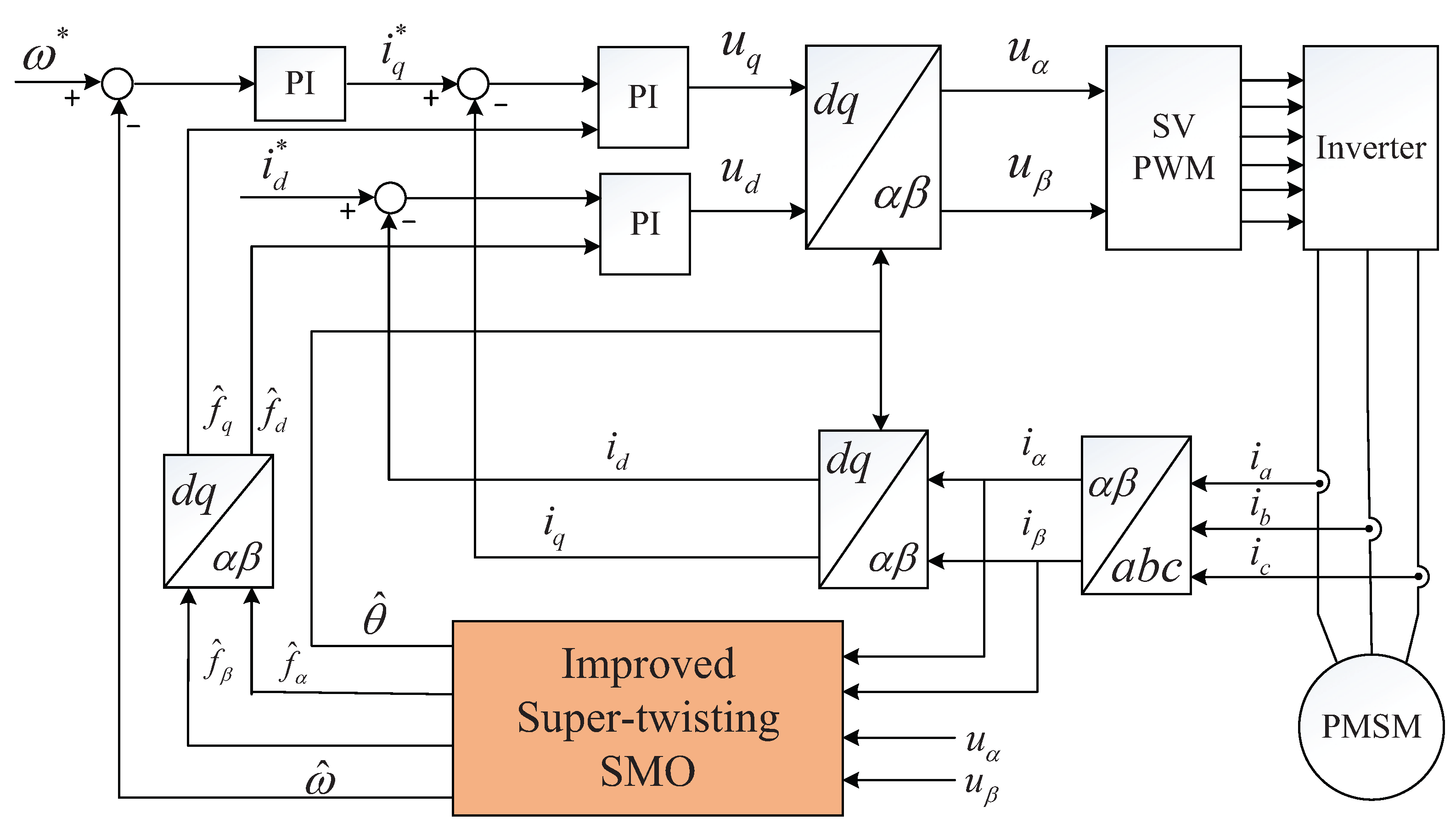
2.1. Improved Super-Twisting High-Order Sliding Mode Observer
2.2. Observer Stability Analysis
- , ;
- .
3. Simulation and Experimental Results
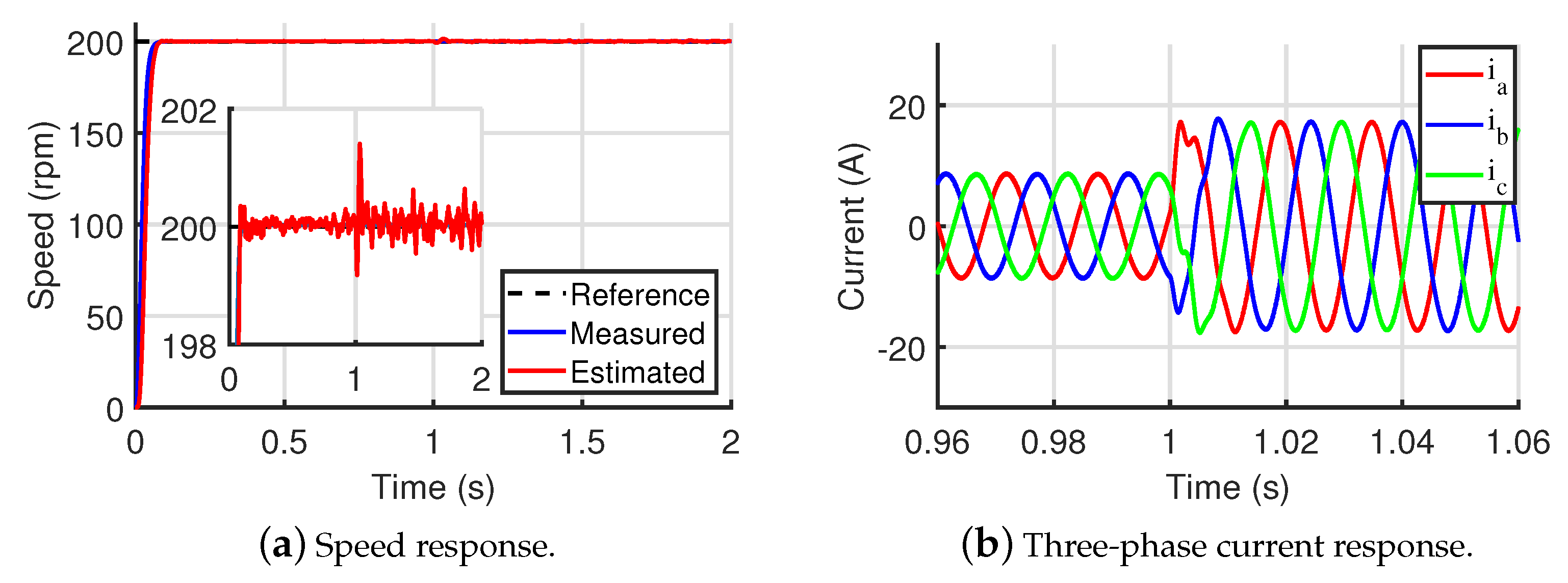
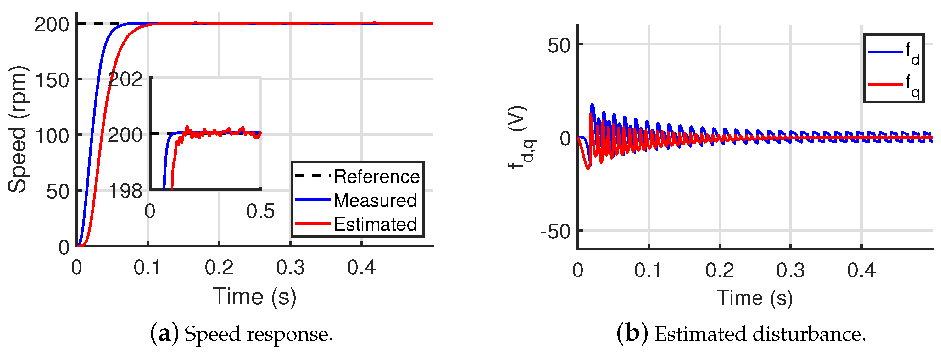
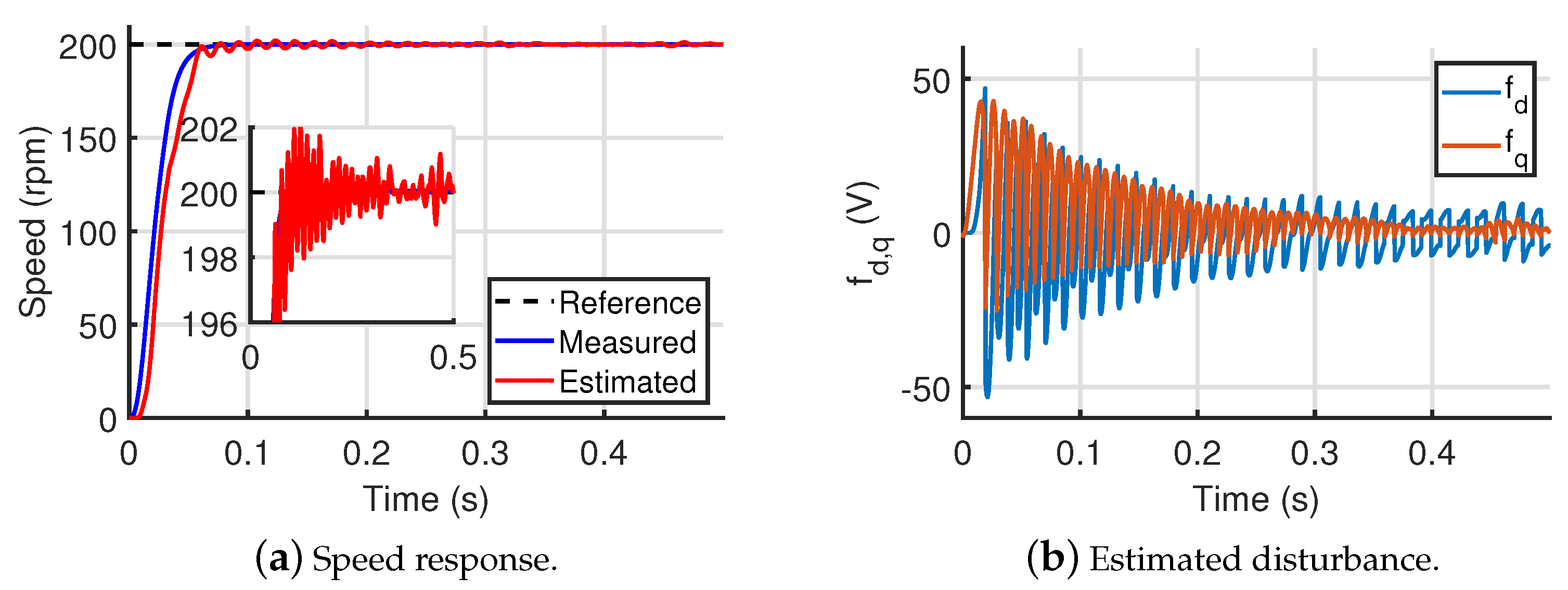
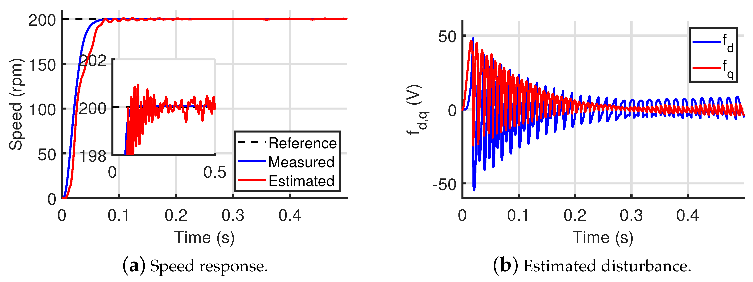
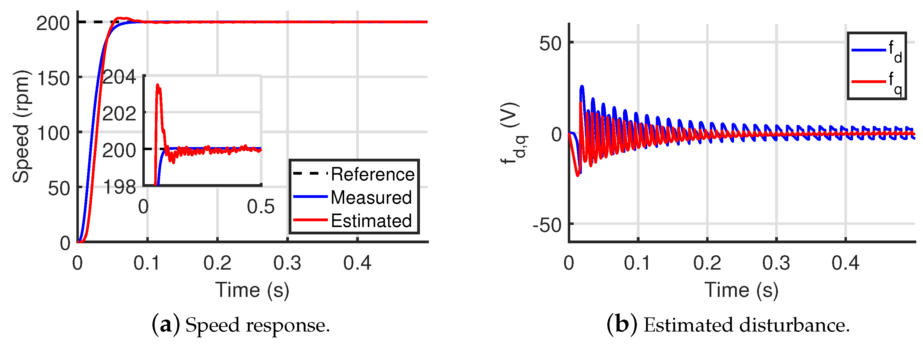
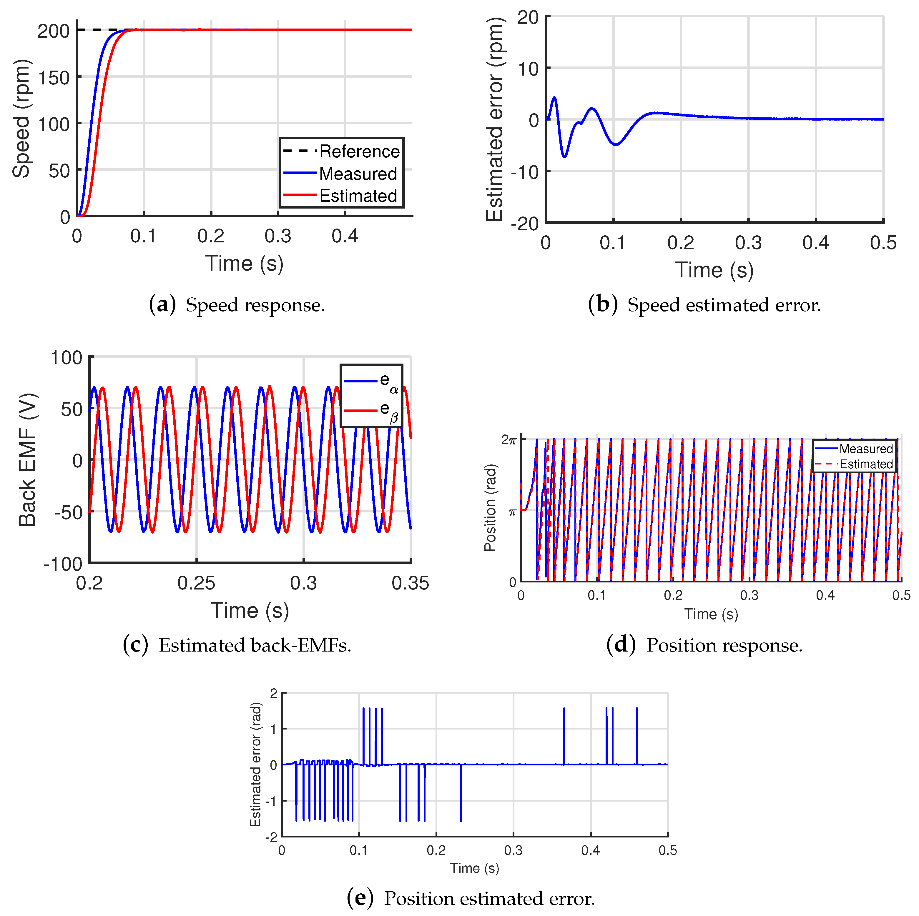
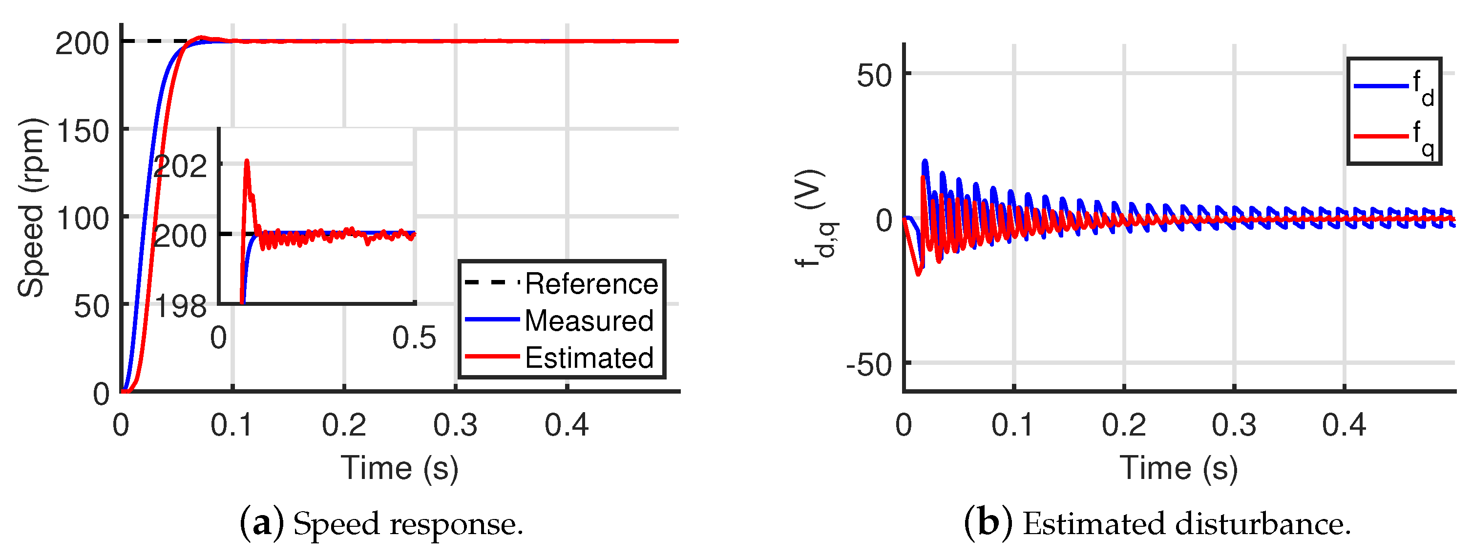
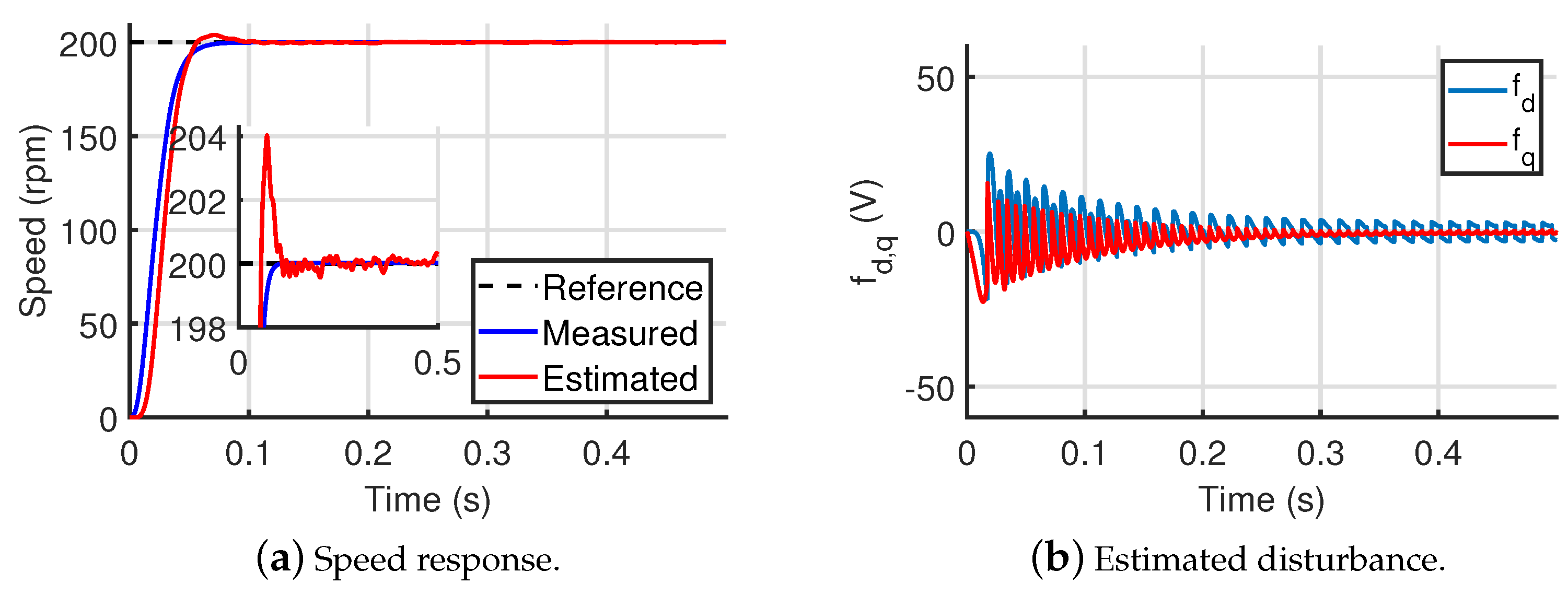
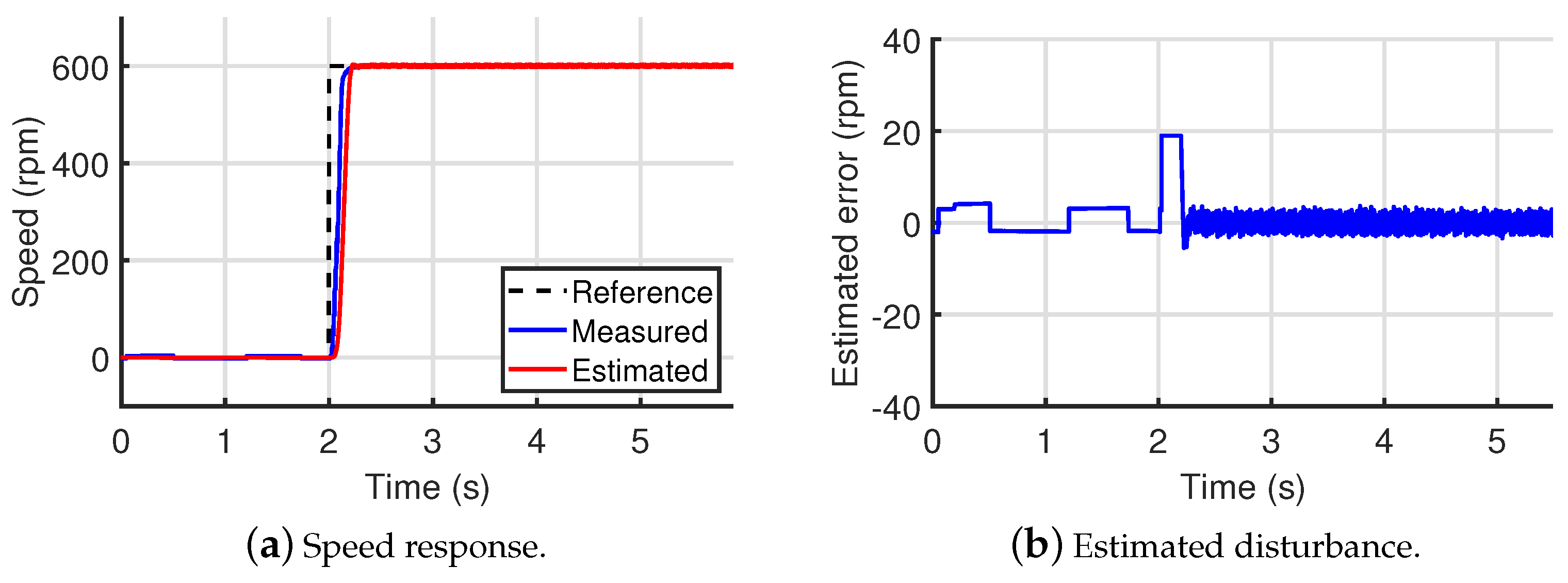
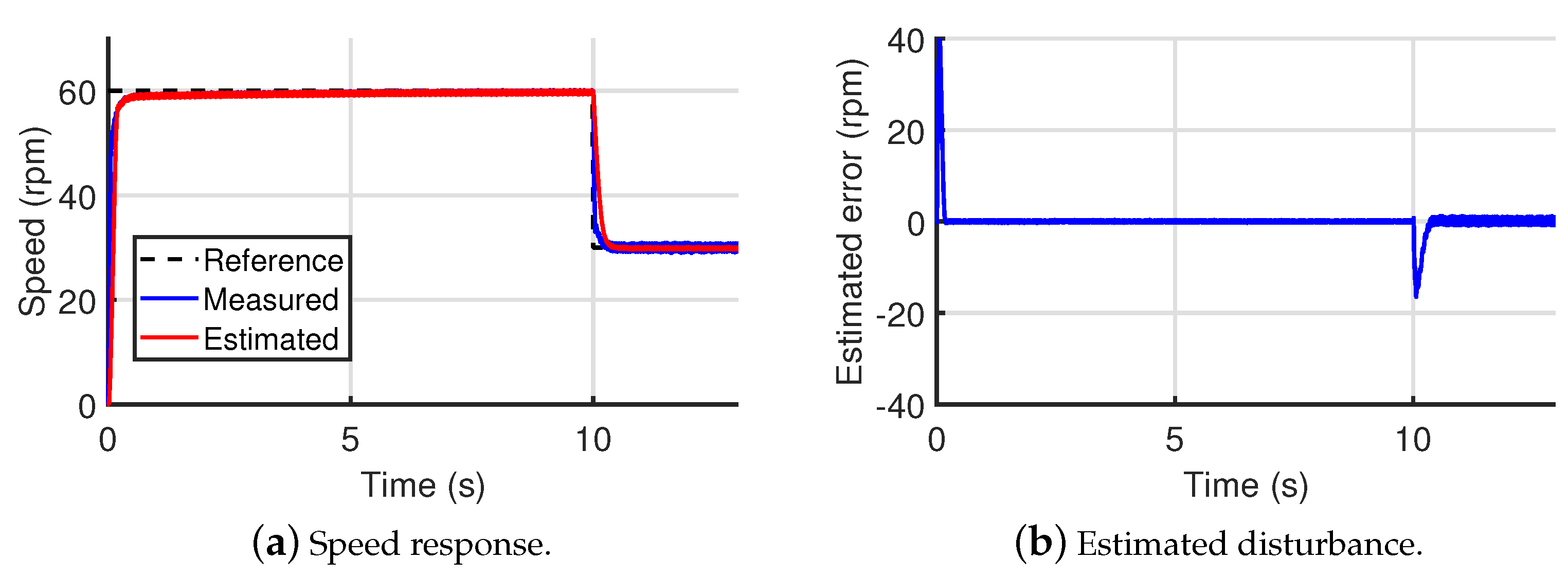
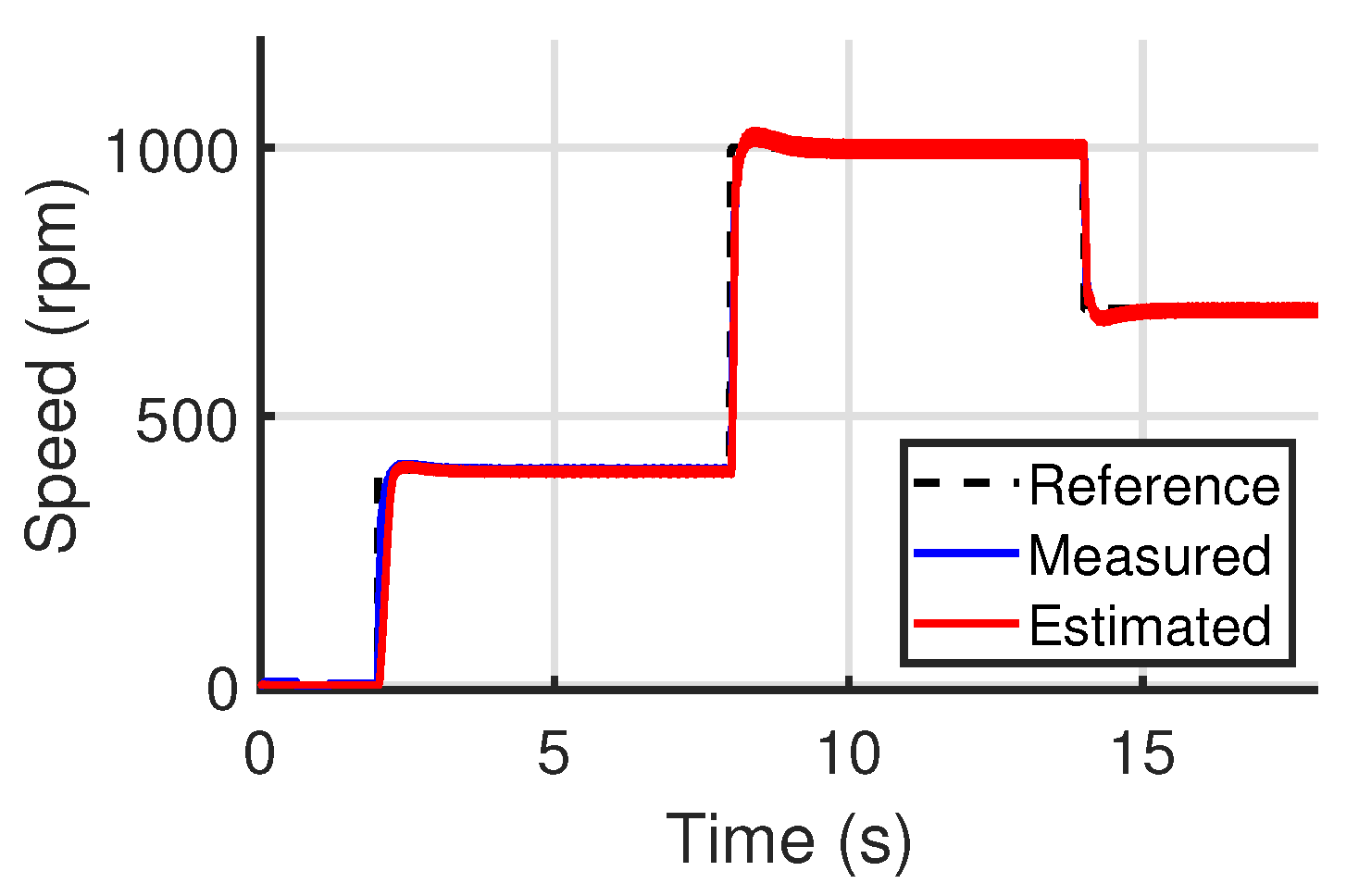
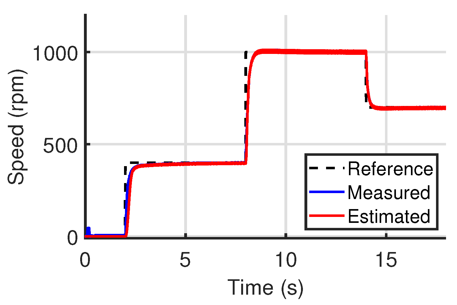
3.1. Simulation Results
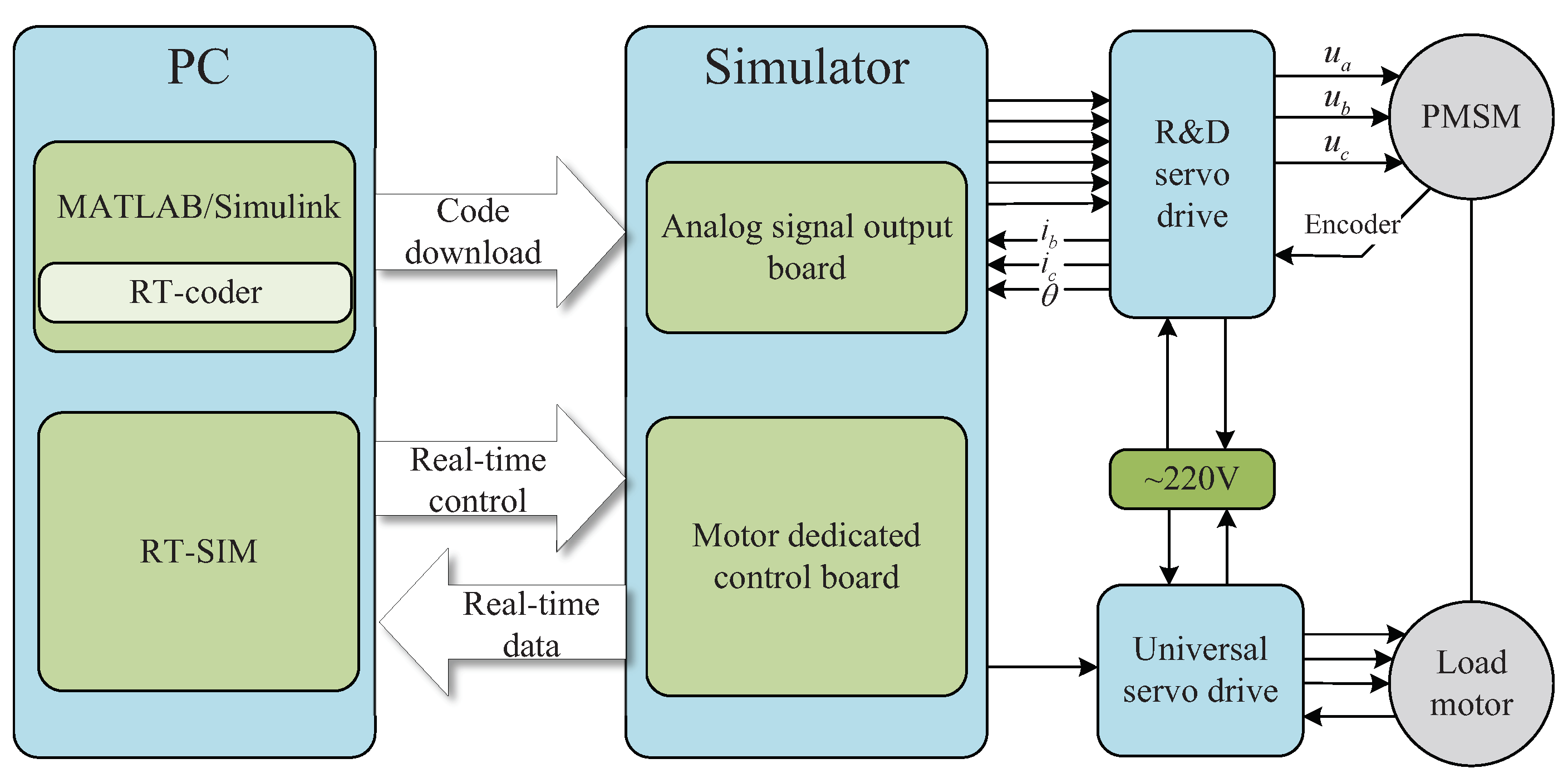
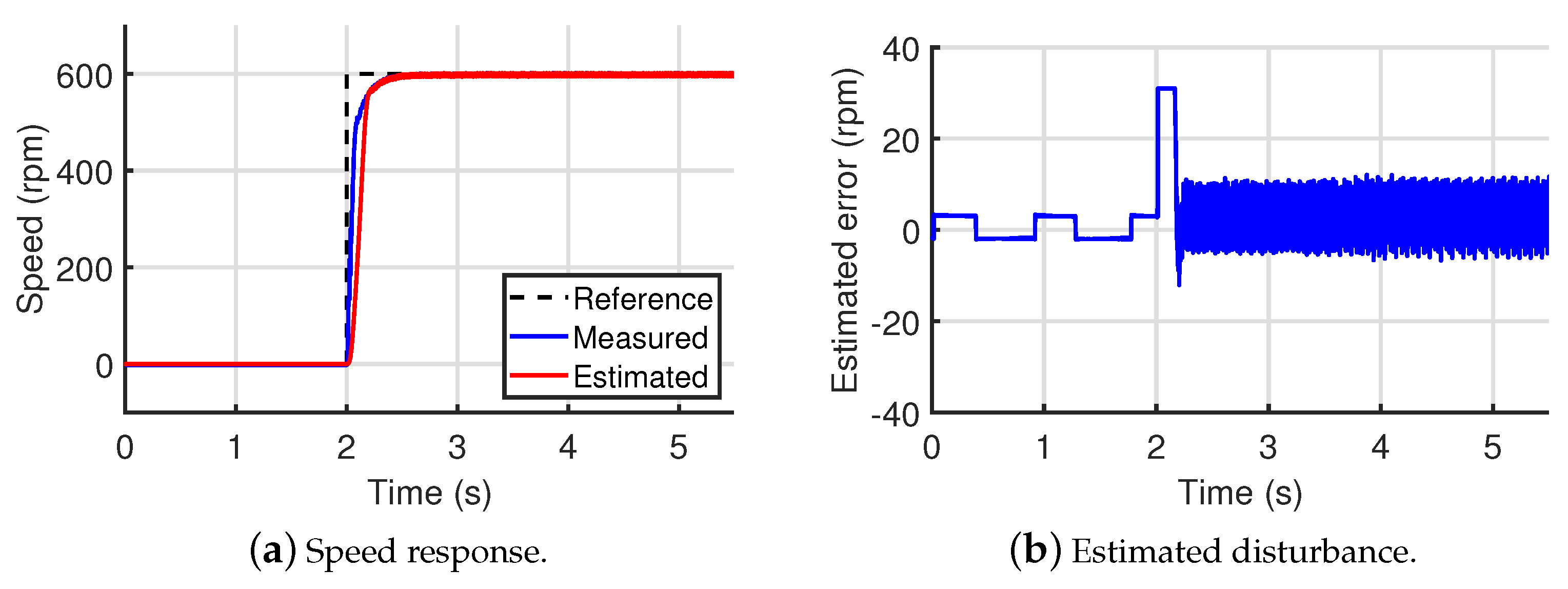
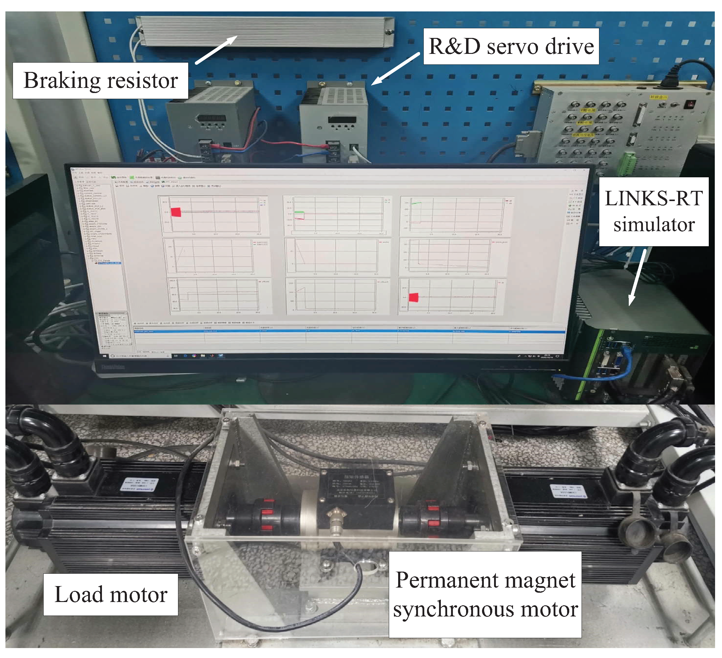
3.2. Experimental Results
4. Conclusions
Author Contributions
Funding
Institutional Review Board Statement
Informed Consent Statement
Data Availability Statement
Acknowledgments
Conflicts of Interest
Abbreviations
| PMSM | Permanent Magnet Synchronous Motor |
| IPMSM | Interior Permanent Magnet Synchronous Motor |
| SPMSM | surface permanent magnet synchronous motor |
| EMF | Electromotive Force |
| SMO | Sliding Mode Observer |
| LPF | Low Pass Filter |
| HSMO | High-order Sliding Mode Observer |
| STA | Super Twisting Algorithm |
References
- Tan, L.N.; Cong, T.P.; Cong, D.P. Neural network observers and sensorless robust optimal control for partially unknown PMSM with disturbances and saturating voltages. IEEE Trans. Power Electron. 2021, 36, 12045–12056. [Google Scholar] [CrossRef]
- Sun, X.; Yu, H.; Yu, J.; Liu, X. Design and implementation of a novel adaptive backstepping control scheme for a PMSM with unknown load torque. IET Electr. Power Appl. 2019, 13, 445–455. [Google Scholar] [CrossRef]
- Liu, X.; Yu, H.; Yu, J.; Lin, Z. Combined speed and current terminal sliding mode control with nonlinear disturbance observer for PMSM drive. IEEE Access 2018, 6, 29594–29601. [Google Scholar] [CrossRef]
- Liu, A.; Yu, H. Smooth-switching control of robot-based permanent-magnet synchronous motors via port-controlled Hamiltonian and feedback linearization. Energies 2020, 13, 5731. [Google Scholar] [CrossRef]
- Zhao, W.; Jiao, S.; Chen, Q.; Xu, D.; Ji, J. Sensorless control of a linear permanent-magnet motor based on an improved disturbance observer. IEEE Trans. Ind. Electron. 2018, 65, 9291–9300. [Google Scholar] [CrossRef]
- Chen, S. Design and performance analysis of an iterative flux sliding-mode observer for the sensorless control of PMSM drives. ISA Trans. 2019, 94, 255–264. [Google Scholar]
- Xiao, D.; Nalakath, S.; Filho, S.R.; Fang, G.; Emadi, A. Universal full-speed sensorless control scheme for interior permanent magnet synchronous motors. IEEE Trans. Power Electron. 2021, 36, 4723–4737. [Google Scholar] [CrossRef]
- Luo, X.; Shen, A.; Tang, Q.; Liu, J.; Xu, J. Two-step continuous-control set model predictive current control strategy for SPMSM sensorless drives. IEEE Trans. Energy Convers. 2021, 36, 1110–1120. [Google Scholar] [CrossRef]
- Reigosa, D.; Ye, G.K.; Martinez, M.; Fernandez, D.; Briz, F. Sensorless control of wound rotor synchronous motors based on rotor high-frequency signal injection. IEEE Trans. Ind. Appl. 2021. [Google Scholar] [CrossRef]
- Repecho, V.; Waqar, J.; Biel, D.; Doria-Cerezo, A. Zero speed sensorless scheme for PMSM under decoupled sliding mode control. IEEE Trans. Ind. Electron. 2021, 31. [Google Scholar] [CrossRef]
- Lee, J.; Kwon, Y.C.; Sul, S.K. Signal-injection sensorless control with tilted current reference for heavily saturated IPMSMS. IEEE Trans. Power Electron. 2020, 35, 12100–12109. [Google Scholar] [CrossRef]
- Accetta, A.; Cirrincione, M.; Pucci, M.; Vitale, G. Sensorless control of PMSM fractional horsepower drives by signal injection and neural adaptive-band filtering. IEEE Trans. Ind. Electron. 2011, 59, 1355–1366. [Google Scholar] [CrossRef]
- Li, H.; Zhang, X.; Yang, S.; Liu, S. Unified graphical model of high-frequency signal injection methods for PMSM sensorless control. IEEE Trans. Ind. Electron. 2020, 67, 4411–4421. [Google Scholar] [CrossRef]
- Xu, W.; Jiang, Y.; Mu, C.; Blaabjerg, F. Improved nonlinear flux observer based second-order SOIFO for PMSM sensorless control. IEEE Trans. Power Electron. 2019, 34, 565–579. [Google Scholar] [CrossRef] [Green Version]
- Li, L.; Zhang, Z.; Wang, C. A flexible current tracking control of sensorless induction motors via adaptive observer. ISA Trans. 2019, 93, 180–188. [Google Scholar] [CrossRef]
- Ge, Y.; Yang, L.; Ma, X. Sensorless control of PMSM using generalized extended state observer and adaptive resistance estimation. IET Electr. Power Appl. 2020, 14, 2062–2073. [Google Scholar] [CrossRef]
- Lu, W.; Tang, B.; Ji, K.; Lu, K.; Yu, Z. A new load adaptive identification method based on an improved sliding mode observer for PMSM position servo system. Energies 2021, 36, 3211. [Google Scholar]
- Chen, S.; Zhang, X.; Wu, X.; Tan, G.; Chen, X. Sensorless control for IPMSM based on adaptive super-twisting sliding-mode observer and improved phase-locked loop. IEEE Trans. Power Electron. 2019, 12, 1225. [Google Scholar] [CrossRef] [Green Version]
- Wang, M.S.; Tsai, T. Sliding mode and neural network control of sensorless PMSM controlled system for power consumption and performance improvement. Energies 2017, 10, 1780. [Google Scholar] [CrossRef] [Green Version]
- Bao, D.; Wu, H.; Wang, R.; Zhao, F.; Pan, X. Full-order sliding mode observer based on synchronous frequency tracking filter for high-speed interior PMSM sensorless drives. Energies 2020, 13, 6511. [Google Scholar] [CrossRef]
- Zaky, M.S.; Metwally, M.K.; Azazi, H.; Deraz, S. A new adaptive SMO for speed estimation of sensorless induction motor drives at zero and very low frequencies. IEEE Trans. Ind. Electron. 2018, 65, 6901–6911. [Google Scholar] [CrossRef]
- Gong, C.; Hu, Y.; Gao, J.; Wang, Y.; Yan, L. An improved delay-suppressed sliding mode observer for sensorless vector-controlled PMSM. IEEE Trans. Ind. Electron. 2020, 67, 5913–5923. [Google Scholar] [CrossRef]
- Kim, H.; Son, J.; Lee, J. A high-speed sliding-mode observer for the sensorless speed control of a PMSM. IEEE Trans. Ind. Electron. 2011, 58, 4069–4077. [Google Scholar]
- Obeid, H.; Fridman, L.M.; Laghrouche, S.; Harmouche, M. Barrier function-based adaptive sliding mode control. Automatica 2018, 93, 540–544. [Google Scholar] [CrossRef]
- Zheng, J.; Wang, H.; Man, Z.; Jin, J.; Fu, M. Robust motion control of a linear motor positioner using fast nonsingular terminal sliding mode. IEEE/ASME Trans. Mechatron. 2015, 20, 1743–1752. [Google Scholar] [CrossRef]
- Ilioudis, V.C. Sensorless control of permanent magnet synchronous machine with magnetic saliency tracking based on voltage signal injection. Machines 2020, 8, 14. [Google Scholar] [CrossRef] [Green Version]
- Gao, H.; Zhang, G.; Wang, W.; Liu, X. Research on an improved sliding mode sensorless six-phase PMSM control strategy based on ESO. Electronics 2021, 10, 1292. [Google Scholar] [CrossRef]
- Ye, M.; Shi, T.; Wang, H.; Li, X.; Xia, C. Sensorless-MTPA control of permanent magnet synchronous motor based on an adaptive sliding mode observer. Energies 2019, 12, 3773. [Google Scholar] [CrossRef] [Green Version]
- Gao, P.; Zhang, G.; Lv, X. Model-free control using improved smoothing extended state observer and super-twisting nonlinear sliding mode control for PMSM drives. Energies 2021, 14, 992. [Google Scholar] [CrossRef]
- Wu, S.; Zhang, J.; Chai, B. Adaptive super-twisting sliding mode observer based robust backstepping sensorless speed control for IPMSM. ISA Trans. 2019, 92, 155–165. [Google Scholar] [CrossRef]
- Zhao, Y.; Liu, X.; Yu, H.; Yu, J. Model-free adaptive discrete-time integral terminal sliding mode control for PMSM drive system with disturbance observer. IET Electr. Power Appl. 2020, 14, 1756–1765. [Google Scholar] [CrossRef]
- Apte, A.; Joshi, V.A.; Mehta, H.; Walambe, R. Disturbance-observer-based sensorless control of PMSM using integral state feedback controller. IEEE Trans. Power Electron. 2020, 35, 6082–6090. [Google Scholar] [CrossRef]
- Lyu, M.; Wu, G.; Luo, D.; Rong, F.; Huang, S. Robust nonlinear predictive current control techniques for PMSM. Energies 2019, 12, 443. [Google Scholar] [CrossRef] [Green Version]
- Shao, M.; Deng, Y.; Li, H.; Liu, J.; Fei, Q. Sliding mode observer-based parameter identification and disturbance compensation for optimizing the mode predictive control of PMSM. Energies 2019, 12, 1857. [Google Scholar] [CrossRef] [Green Version]
- Moreno, J.A.; Osorio, M. Strict lyapunov functions for the super-twisting algorithm. IEEE Trans. Autom. Control. 2012, 57, 1035–1040. [Google Scholar] [CrossRef]


| Description | Value | Unit |
|---|---|---|
| rated speed | 1000 | |
| rated torque | 10 | N·m |
| stator resistance | 0.93 | |
| d-and q-axis inductance | 3 | mH |
| permanent magnet flux | 0.32 | Wb |
| moment of inertia | 0.0027 | kg·m |
| Speed | Method | Steady-State Error | Tracking Time | Estimated Time |
|---|---|---|---|---|
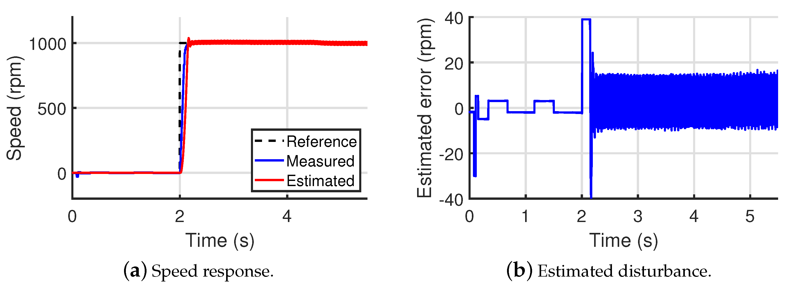
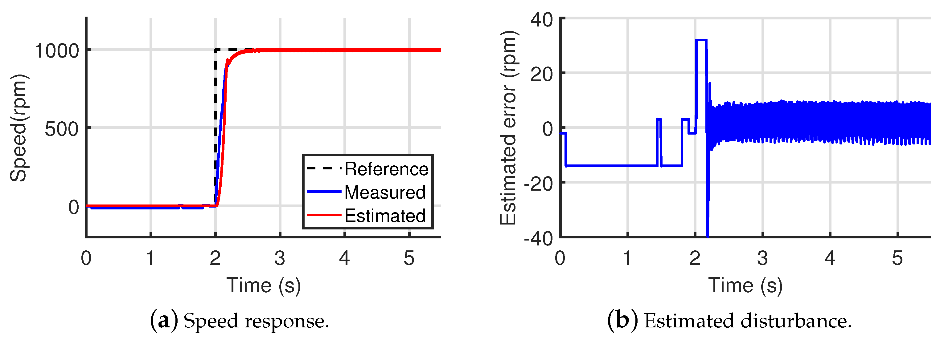
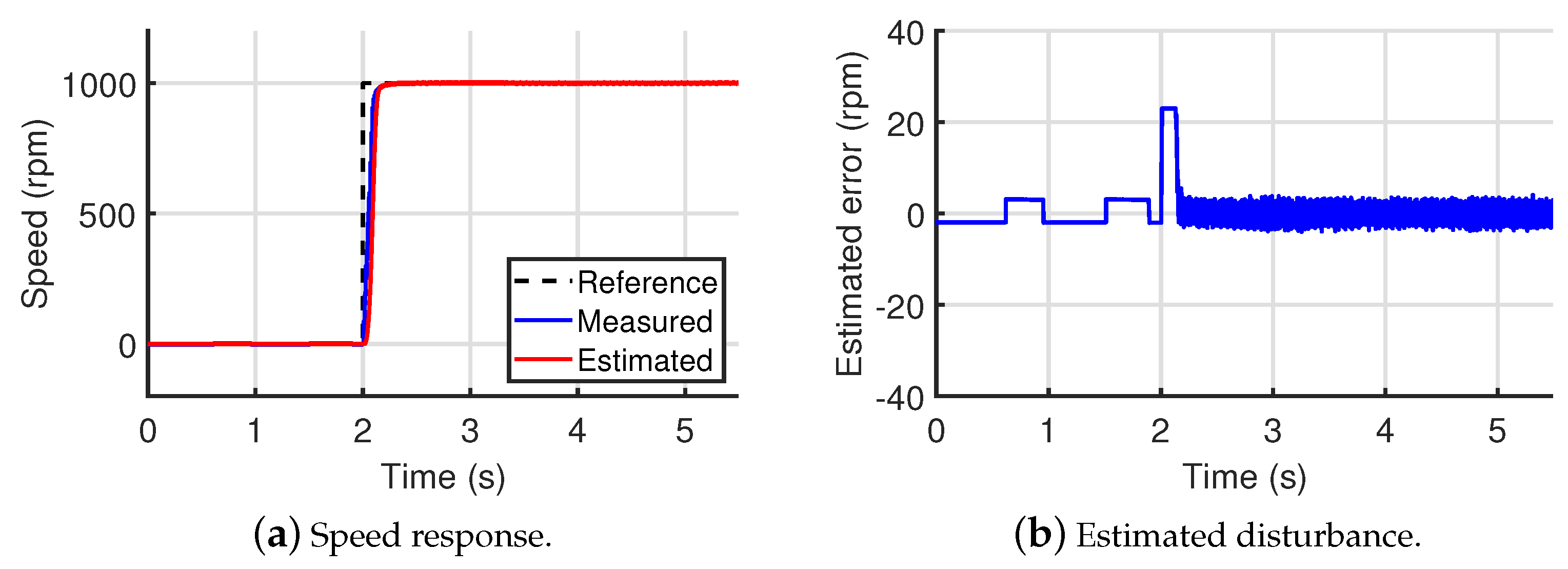
| 1000 rpm | traditional SMO | 10 rpm | 2.19 s | 2.22 s |
| traditional STA | 7 rpm | 2.55 s | 2.56 s | |
| proposed observer | 4 rpm | 2.20 s | 2.20 s | |
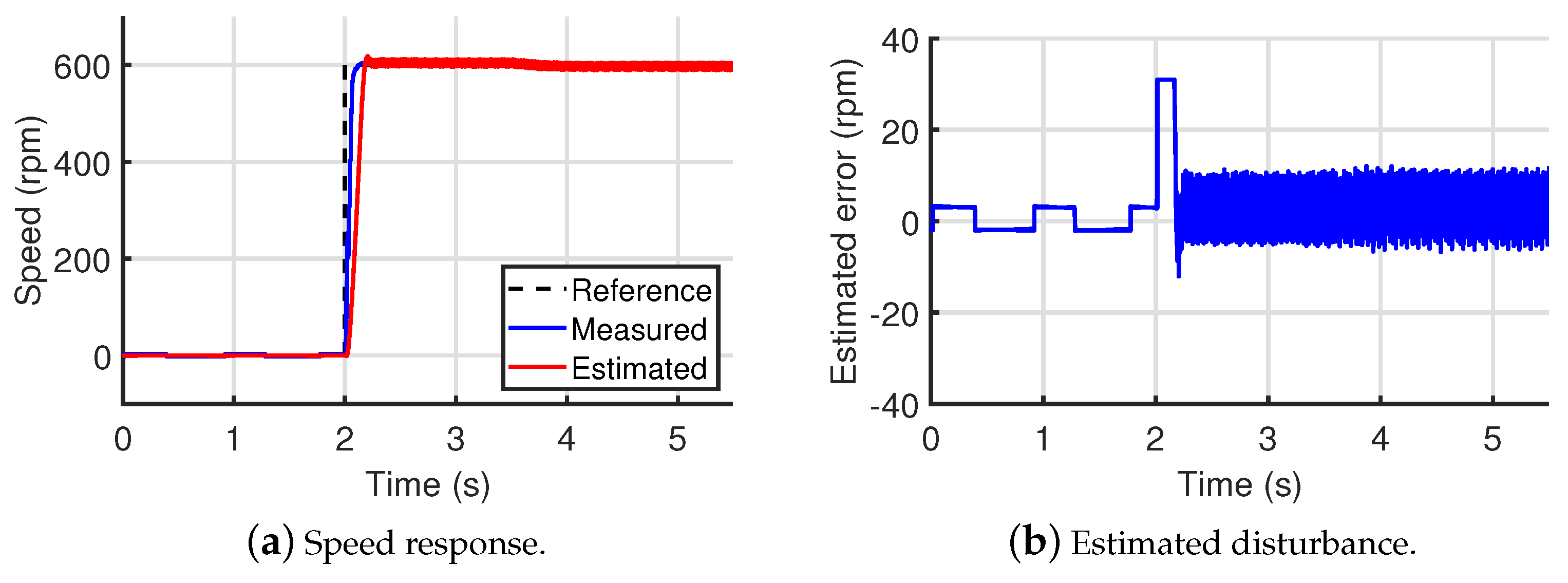
| 600 rpm | traditional SMO | 9 rpm | 2.23 s | 2.25 s |
| traditional STA | 5 rpm | 2.51 s | 2.52 s | |
| proposed observer | 3 rpm | 2.22 s | 2.22 s | |
| rpm | traditional SMO | 1 rpm | 0.9 s | 1 s |
| traditional STA | 0.8 rpm | 0.3 s | 0.5 s | |
| proposed observer | 0.5 rpm | 0.3 s | 0.4 s |
Publisher’s Note: MDPI stays neutral with regard to jurisdictional claims in published maps and institutional affiliations. |
© 2021 by the authors. Licensee MDPI, Basel, Switzerland. This article is an open access article distributed under the terms and conditions of the Creative Commons Attribution (CC BY) license (https://creativecommons.org/licenses/by/4.0/).
Share and Cite
Zhao, Y.; Yu, H.; Wang, S. An Improved Super-Twisting High-Order Sliding Mode Observer for Sensorless Control of Permanent Magnet Synchronous Motor. Energies 2021, 14, 6047. https://doi.org/10.3390/en14196047
Zhao Y, Yu H, Wang S. An Improved Super-Twisting High-Order Sliding Mode Observer for Sensorless Control of Permanent Magnet Synchronous Motor. Energies. 2021; 14(19):6047. https://doi.org/10.3390/en14196047
Chicago/Turabian StyleZhao, Yujiao, Haisheng Yu, and Shixian Wang. 2021. "An Improved Super-Twisting High-Order Sliding Mode Observer for Sensorless Control of Permanent Magnet Synchronous Motor" Energies 14, no. 19: 6047. https://doi.org/10.3390/en14196047
APA StyleZhao, Y., Yu, H., & Wang, S. (2021). An Improved Super-Twisting High-Order Sliding Mode Observer for Sensorless Control of Permanent Magnet Synchronous Motor. Energies, 14(19), 6047. https://doi.org/10.3390/en14196047