1. Introduction
The demand for energy increases day by day as the world population increases, sharply causing a drastic increase in the emissions of greenhouse and air pollutant gases and liquids. The use of sustainable and renewable energy sources as well as the utilization of waste heat for cooling and heating purposes has attracted the attention of researchers for many years. However, there is a serious problem with using these kinds of energy sources, and that is their time-dependent character. For instance, most of the renewable energy sources are intermittent thermal sources (such as solar energy or outdoor air as an energy source). To have a continuous operated system, thermal energy in a peak period should be stored and released in demanding time. Therefore, many studies on thermal energy storage have been done and reported in the literature (e.g., [
1,
2]). In general, thermal energy storage systems can be classified into three groups as sensible heat storage (e.g., [
3,
4]), latent heat storage (e.g., [
5,
6,
7,
8]), and chemical heat storage (e.g., [
9,
10,
11]). Among these groups, solid/liquids thermal energy storage has taken the attentions of researchers recently due to its simple working principle.
Thermal energy storage in cavities has been widely studied in the literature due to its wide applications in practical engineering problems. Most of the studies on phase change in a cavity have been done on steady heating or cooling wall in which wall temperature does not change over time. However, in many applications such as the use of PCM for thermal storage of solar energy or the use of a PCM layer as thermal insulation in a wall, a periodic temperature or heat flux change exists. The number of studies on the cavities filled with PCM under a periodic temperature or heat flux is limited compared to steady temperature or heat flux imposed to a wall of the cavity. Kant et al. [
12] studied the melting behavior of phase change materials (PCMs) during a cyclic heating and cooling process, computationally. A sine function of heat flux was considered at one wall of the container to provide heating and cooling of the PCMs, and the other walls of the cavity are insulated. The heat is imposed on an aluminum wall and then transferred to the fluid in the cavity. The sine function that they used for the heated/cooled surface is,
where
t is time in minute and changes between 0 and 90. It was shown that despite the same amount of energy delivered to PCM, variable heating and cooling provides faster melting and solidification, respectively. Bouzennada et al. [
13] did a study on a two-dimensional simulation of the melting/solidification process of a phase change material (PCM) in a square cavity. The size is 5 × 5
and all cavity’s walls are thermally insulated, except for the left wall on which a sine function heat flux was imposed,
where
t is time in second. It was found that the PCM melting time was shorter than the solidification time. Chabot and Gosselin [
14] studied the solid-liquid phase change around a tube located in an infinite PCM domain for latent energy storage with cyclic thermal loading and unloading. Transient cyclic heat flux at the surface of the tube was imposed as,
where
and
are heat flux per unit length of the tube and period, respectively. Their results showed that the size of the affected region by the heating and cooling increases when the period or Stefan number increases, but it is less sensitive to the Rayleigh number. The effect of charging and discharging of multi-layers PCMs in coaxial cylinders with a time-periodic boundary condition was numerically investigated by Sadeghi et al. [
15]. They assumed that the inner cylinder is subjected to a hot working fluid in which bulk temperature is changed over time. They supposed that the inner flow is a discharged heat flow from a factory with a changeable temperature over time as,
where
and
express the amplitude and periodicity of bulk temperature oscillation in the sinusoidal function. They declared that comparing the results for one, three, and five-layer heat exchangers shows that using the multi-layers’ system due to high capacity in storing latent energy is appropriate. Rakotondrandisa et al. [
16] studied melting-freezing in a cavity in which one vertical wall is at cold temperature and the temperature of the front wall changes between hot and cold temperatures for the melting and freezing processes. They declared that if the PCM does not solidify entirely, the effectiveness of the system may be considerably reduced.
Although natural convection plays an important role in solid/liquid phase change in a cavity, there are many applications in which the effect of buoyancy can be neglected. Recently the application of solid/liquid thermal storage for shuttles in space has become popular and NASA designed and produced PCM heat exchangers [
17] for spacecraft thermal control. Furthermore, PCM can also be used for temperature control of electronic equipment in satellites e.g., [
18]. PCM is starting to be used in micro-devices such as mobile phones and electronic equipment e.g., [
19]. For small devices, the value of Rayleigh number of the cavity in which PCM exists is small and the effect of buoyancy can be neglected.
The aim of the present study is different than the above studies. The aim of this study is to (a) minimize the number of governing parameters for a solid/liquid phase change in a cavity by using appropriate dimensionless parameters, (b) to establish a chart in terms of dimensionless parameters to predict the situation of phase change in the cavity, and (c) to recommend the best values of governing parameters in order to have high thermal storage capacity. The governing equations are expressed in dimensionless form and this leads to yielding of two dimensionless parameters as dimensionless frequency and Stefan number. Wide ranges of values for these dimensionless parameters are considered and heat transfer in the cavity is analyzed through this study. Based on the obtained results, the aimed graph in terms of Stefan number and dimensionless frequency is established. Furthermore, the ratio of the latent heat to total thermal storage in terms of two dimensionless parameters is also calculated to predict the percentage of latent thermal storage in a cavity under a period temperature change. To the best of knowledge, this study is original and presents significant hints for thermal designers of the solid/liquid phase change thermal storage systems under a periodical temperature change.
2. Problem Definition
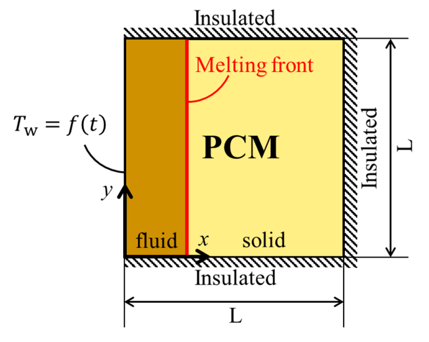
The domain considered in this study is shown in
Figure 1. The studied domain is a square cavity filled completely with PCM and the model is two-dimensional. All surfaces of the cavity are insulated except the left wall. The left wall is under a periodical temperature change. The periodic temperature of the left wall (i.e.,
) is expressed by the following sinusoidal function.
where
is the initial temperature of the PCM,
a is the amplitude, and
is frequency of the applied sinusoidal temperature change.
The employed PCM is Paraffin (RT35HC) and the thermophysical properties of the PCM are presented in
Table 1. Assumptions that are used in this study are (a) all thermophysical properties for the PCM are constant and do not change with temperature, (b) gravity does not play an important role in the heat transfer (the Rayleigh number is small), (c) the radiation heat transfer is neglected.
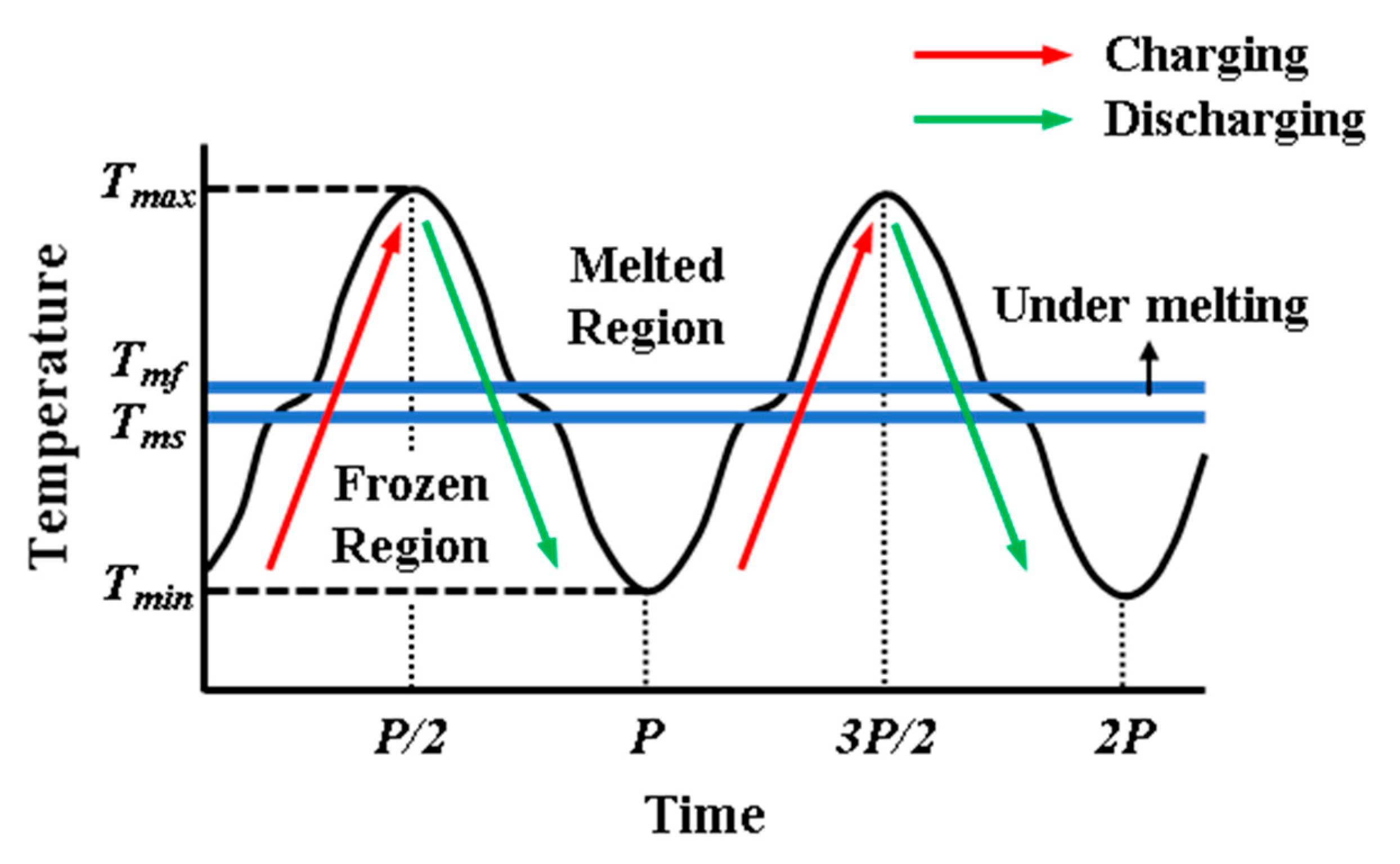
Figure 2 shows the process of heat transfer during the thermal storage through the cavity, schematically. It illustrates the change of temperature in the cavity near hot wall with time. If the temperature of PCM is less than
, the region is solid. The phase of PCM is liquid when the temperature of PCM is greater than
. The PCM is under melting in the region between
and
. The amplitude and period are also shown in
Figure 2. As it can be seen, there are two processes in solid/liquid thermal storage systems, as charging and discharging processes. Each process consists of two types of heat storage as sensible and latent heat storage. Hence, the total thermal storage is the summation of sensible and latent heat storage for each process.
The present study was performed for wide range of Stefan number (0.1 < Ste < 1.0) and dimensionless frequency (0.23 <
< 2.04).
Table 2 is presented to show the corresponding minimum and maximum dimensional values of Stefan and dimensionless frequency in the present study. The initial temperature (
) and length of the square cavity were 308.15 K and 0.01 m, respectively, for all runs of this study.
4. Computational Details
The heat conduction equation is solved numerically by using OpenFoam 6 software using Finite Volume Method. The number of square mesh was 100 × 100. Our computational study showed that it is sufficient to divide a period to 100,000-time steps to obtain accurate results. Therefore, the time interval was not constant in this study and changed by the value of the period. “chtMultiRegionFoam” which is a solver of OpenFoam, was used to solve the governing equation. This solver can be used for unsteady single-phase flow as well as for unsteady conjugate heat and fluid flow. In order to solve the source term of Equation (6), a sub-program of OpenFoam named as “solidificationMeltingSource” was added to chtMultiRegionFoam solver. The relaxation factor was fixed as 0.5 for all runs of this study. The absolute and relative tolerances were 10−9 and 0.0001, respectively. Parallel processing (with 6 cores) was used to reduce the run time. The value of “nOuterCorrectors” showing the number of iterations at each time step was 30. No convergence criterion is needed to stop the program since the problem is a time-dependent periodic problem. The program was terminated when enough cycles were done to obtain steady periodic results. The program was stopped time by time to check whether the steady periodic results were achieved. The checking was done by plotting and observing the temperature at three points of x* = 0.01, 0.5, and 0.98 through all cycles. The running of the program continued until it reached a steady periodic result.
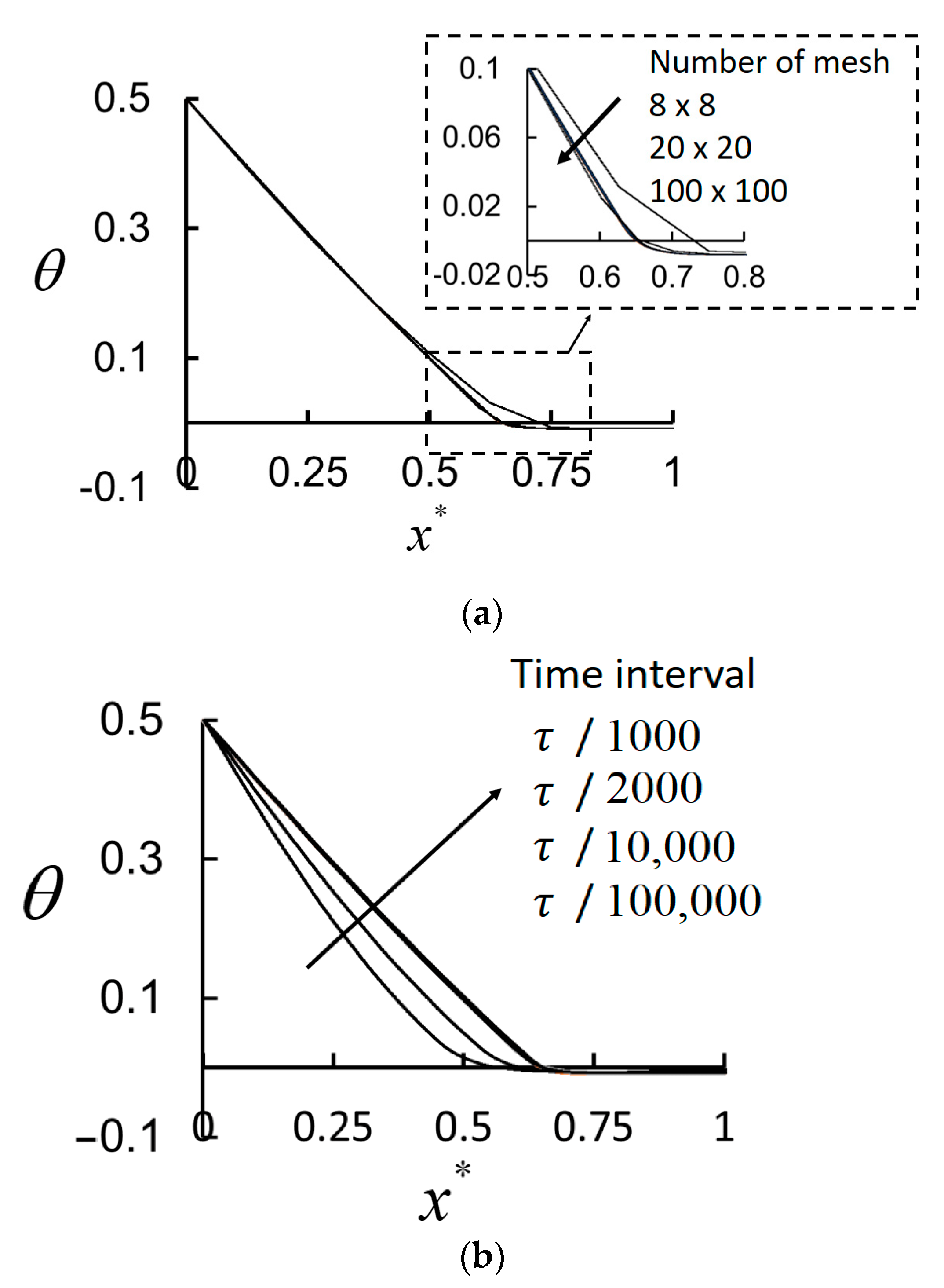
Grid independency for the employed time interval was checked.
Figure 3a shows the performed study for mesh independency. Since the convection heat transfer is neglected, it is possible to obtain accurate results with a small number of mesh. As it can be seen from
Figure 3a, the results of
mesh overlap the obtained values of
mesh number. In this study,
mesh is used to prevent the possibility of any wrong results due to the number of mesh.
Figure 3b shows the study done to check the time interval. The results of
/10,000 and
/100,000 match each other. In this study
/100,000 is used to be sure of the accuracy of the obtained results.
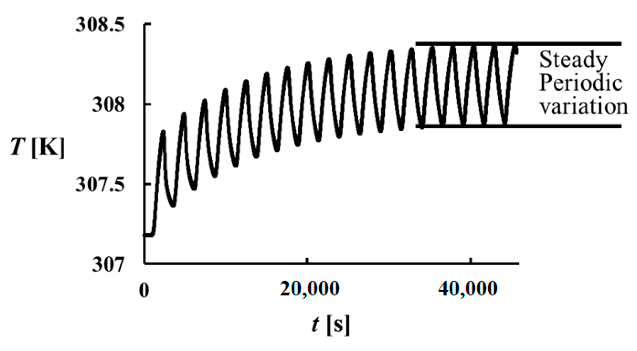
One of the difficulties in the performed computations is the long run time. An initial condition is assigned to the software, however, to obtain steady periodical changes for the temperature, a long running time is required.
Figure 3 shows the change of temperature variation at
x = L (or
x* = 1) during a run for the problem with
= 2.04 and Ste = 0.6. As it can be seen, at least 17 melting and freezing cycles should be finished in order to have a steady periodical cycle. In this study, it is accepted that a steady periodical change in the cavity exists when the variation of temperature at
x* = 0.01, 0.5 and 0.98 becomes periodically steady (see
Figure 4).
The total melting time (
) is calculated when the PCM in the entire cavity melts, in other words when
= 1 for the entire cavity. Heat storage in the cavity consists of sensible and latent heat storage. That is why a parameter as the ratio of latent heat storage is defined and used in this study,
where
and
are latent and total heat storage in the cavity for a period, and
shows the ratio of latent heat storage. The minimum value of
is zero, indicating that all stored heat is done by sensible storage while it is 1 (i.e.,
) showing that all stored heat is performed by latent heat storage. The value of
Q is calculated by the following equation
A is the heat transfer area of the heated/cooled cavity, which is A = L. 1
. The latent heat is found by subtraction of latent heat and sensible heat transfer rates.
Sensible heat can be easily calculated from the following equation,
where
m is the mass of PCM inside the cavity.
and
are the maximum and minimum average temperature in the cavity during the last cycle.
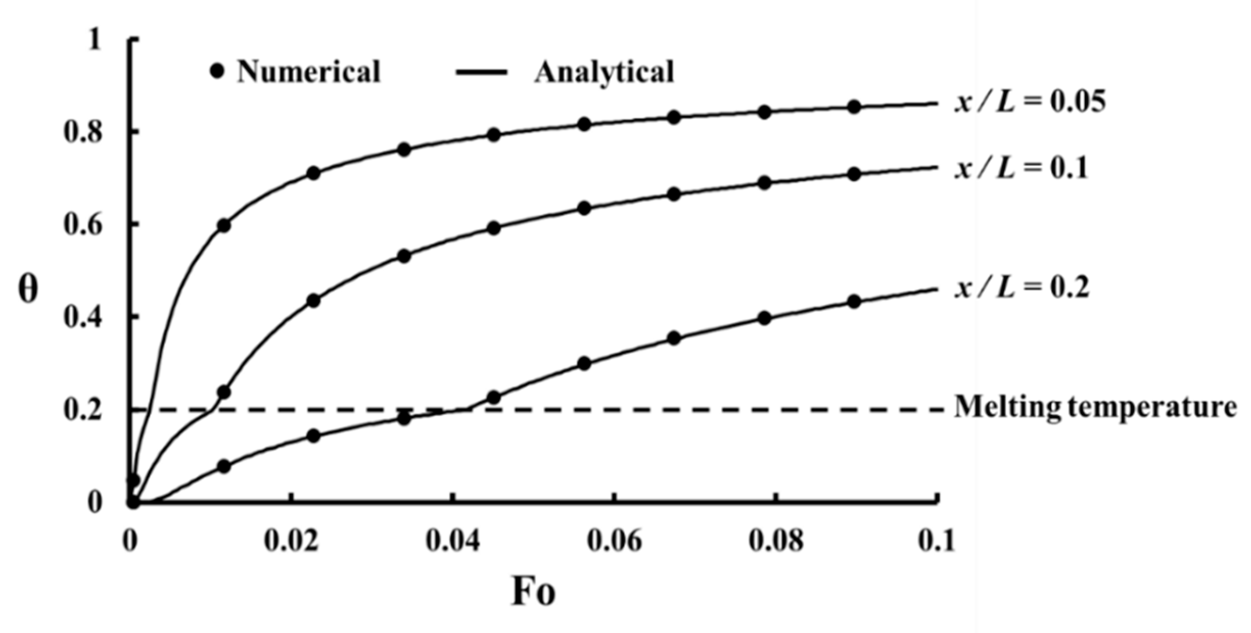
5. Validation Study
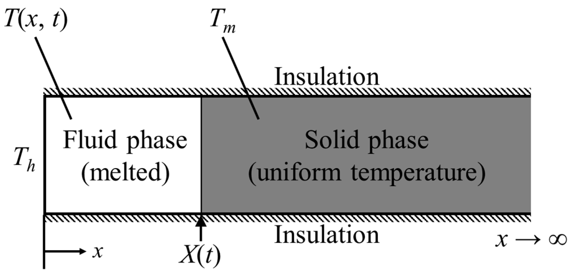
For the validation study, the melting of a PCM under pure heat conduction in a semi-infinite medium is analyzed as shown in
Figure 5. Initially, the domain is at
and suddenly the temperature of the left wall becomes
where
. The melting temperature of PCM (
) is between
and
. The energy equation for this problem is 1D heat conduction with solid/liquid phase change. There are two temperatures for this problem as the temperature of the frozen phase (
and the temperature of the melted phase (
. The analytical solution of energy equation for this problem is presented in literature and equations for
and
were found as [
21],
where
is the location for which the temperature is required.
is thermal conductivity ratio as
and
shows the position of the interface between the solid and fluid, and it is defined by the following equation,
The coefficient of
is the root of the following equality,
and
are Stefan number for the melted and unmelted regions and defined as,
For the same problem, the computational results were found by using OpenFoam 6 software. A rectangular domain with a length of 500 mm and height of 10 mm is considered. Since the length of the domain is too long, the domain can be accepted as a one-dimensional semi-infinite heat conduction. The numerical results of the study are valid for the region near the heated surface since it is too far from the end surface and the end effect is small in this region. The number of mesh in transverse direction is not important since the problem is one dimensional, but the number of mesh in x-direction was 1000. The time interval for obtaining an accurate solution was 1 s. The problem is solved for RT35HC PCM for which the thermophysical properties are shown in
Table 1. Since we have one melting temperature in the analytical solution, the melting temperature is considered as the average of
and
.
Figure 6 shows the comparison of the analytical and numerical solutions and as it can be seen that a good agreement between them exists indicating sufficient accuracy of the results of the present study.
6. Results and Discussion
To discover how heat flow changes by time in the cavity, the change of temperature and melting fraction at three points as . are plotted. Therefore, it is possible to discover the variation of heat flow in three regions as (a) the region close to the hot wall, (b) the middle region, and (c) the right wall region, which is far from the heat source. The plotted figures show how these regions are affected by the sinusoidal variation of temperature at the hot wall. The obtained results and plotted diagrams discussed are presented below.
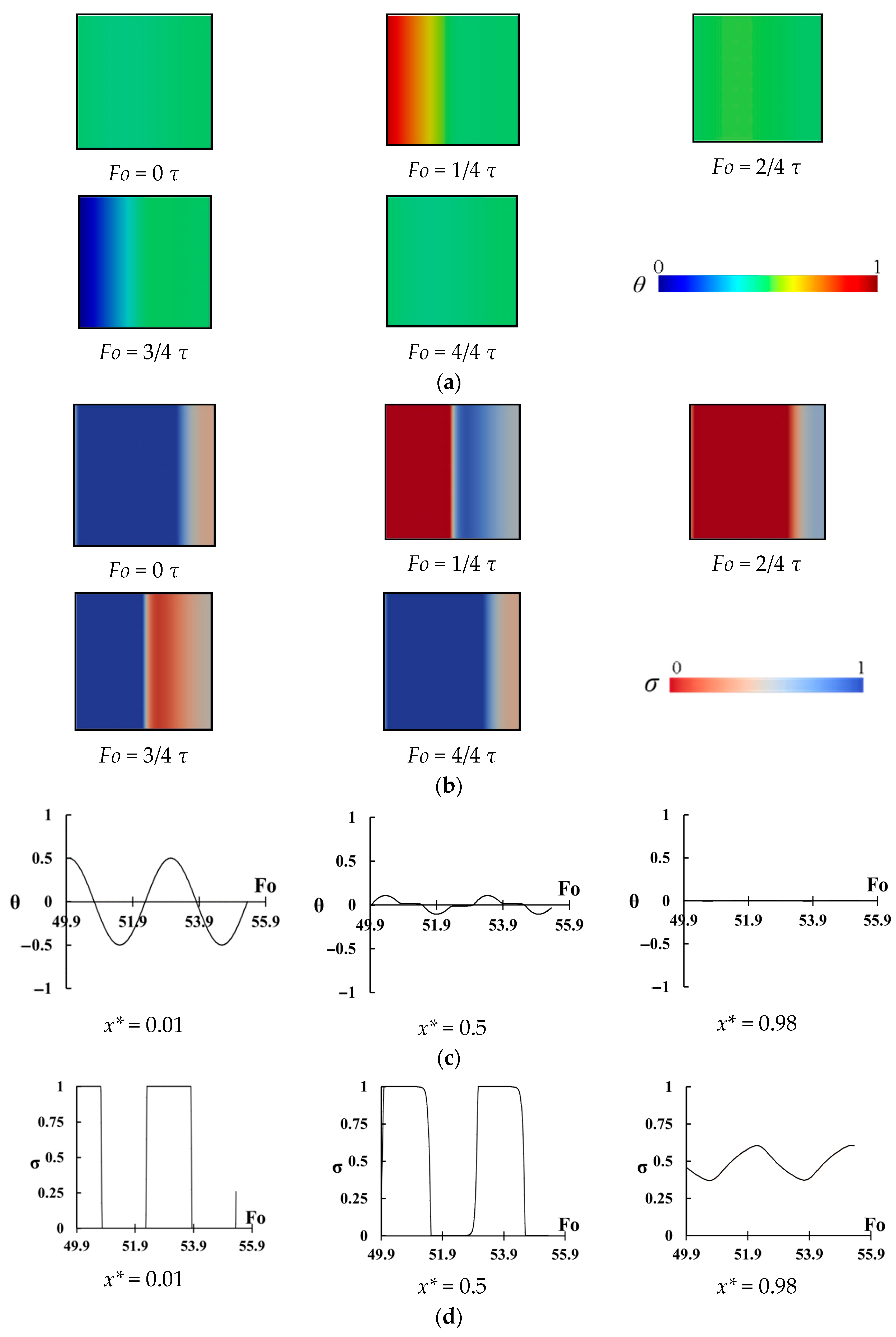
The change of temperature and the melting fraction in the cavity with Ste = 0.6 and
= 2.04 for different instants of a period is shown in
Figure 7a,b. As it can be seen there is no melting when
but by increasing time, the melting from the left wall approaches to the right wall, which is insulated (
. By decreasing wall temperature, freezing starts from the left wall while the right region of the cavity is hotter than left wall region. This time, freezing starts to move from the left region to the right region and reduces the temperature of the right region. It can be seen that the temperature in the region close to the right wall does not change and the maximum temperature change exists in the left region. It seems that melting in the right wall is negligible and it behaves like a dead region.
Figure 7c shows the change of temperature at three points inside the cavity as
. A large variation of temperature can be seen for the point of
which is close to the heated wall. The temperature at the center does not highly change but it exceeds the PCM melting range showing that complete freezing and melting process occurs in the middle region (i.e., latent heat is stored). However, for the points of
there is almost no change of temperature, and the phase of this region is between solid and fluid (slurry region) and almost no heat is stored by this region. Hence, the right region is almost inactive, and it does not play a significant role in the thermal storage, however it occupies space in the cavity.
Figure 7d shows all details of the melting and freezing process. It shows the change of melting ratio (i.e.,
) with dimensionless time for the same three points. For the point of
, a complete melting and freezing is seen. Even, the phase of this region does not change (it is solid or liquid) for a long time and this region becomes overheated (for melting period) or subcooled (for the freezing period). For the point of
, again a complete melting and freezing process is seen, however, there is a negligible overheating or subcooling process for the central region. Therefore, complete latent heat storage exists for this region. However, for the point of
, the view is different. There is a small change of
showing that this region does not play a significant role in thermal storage and that is why the right region can be called a dead region. This region just occupies space without storing energy causing reduction of thermal storage power.
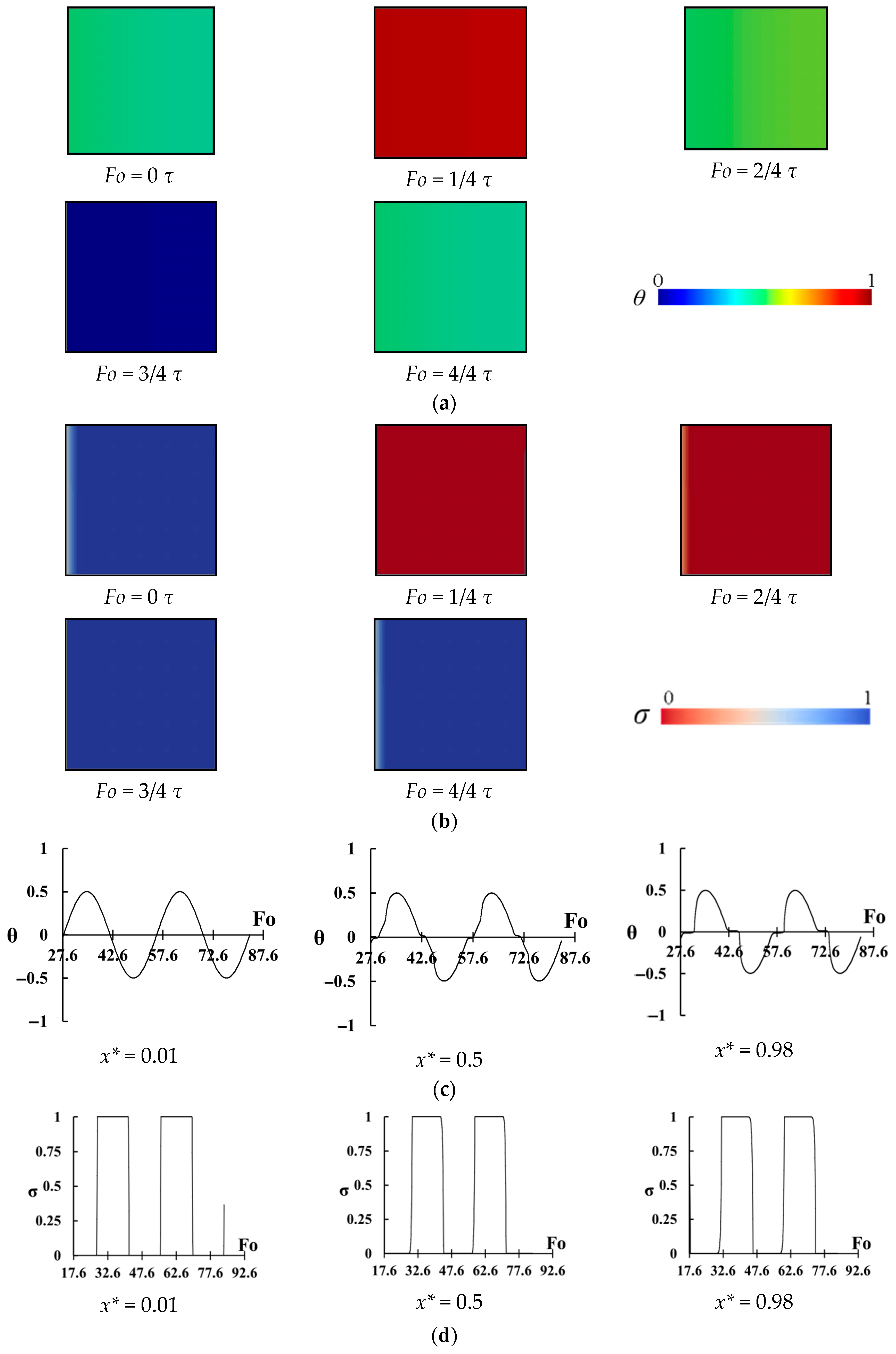
The change of temperature and melting ratio in the cavity with Ste = 0.6 and
= 0.23 is shown in
Figure 8a,b. Similar to
Figure 7a,b, the melting starts from the left wall and moves to the right wall. However, it seems that the temperature of the right region increases extremely, and it becomes highly above the melting temperature (
Fo = 1/4
) and almost a uniform temperature exists. In other words, the right region is overheated, and it seems that the sensible heat is considerably stored. By reducing the temperature at the left wall, freezing starts from this wall and approaches to the right region. This time, the cavity becomes considerably lower than the melting point (
Fo = 3/4
) and again a uniform low temperature exists in the entire cavity. The variations of temperature at
points are also plotted and shown in
Figure 8c. As it can be seen, not only the temperature change at
is considerable but also a high variation of temperature for the points
exists.
Figure 8 shows that in addition to latent heat, the sensible heat storage is considerably stored in the PCM during the process. The change of
with
can be seen from
Figure 8d. The latent heat is also stored in the entire cavity, however as it is mentioned before, it seems that sensible heat storage for this case may compete with the stored latent heat.
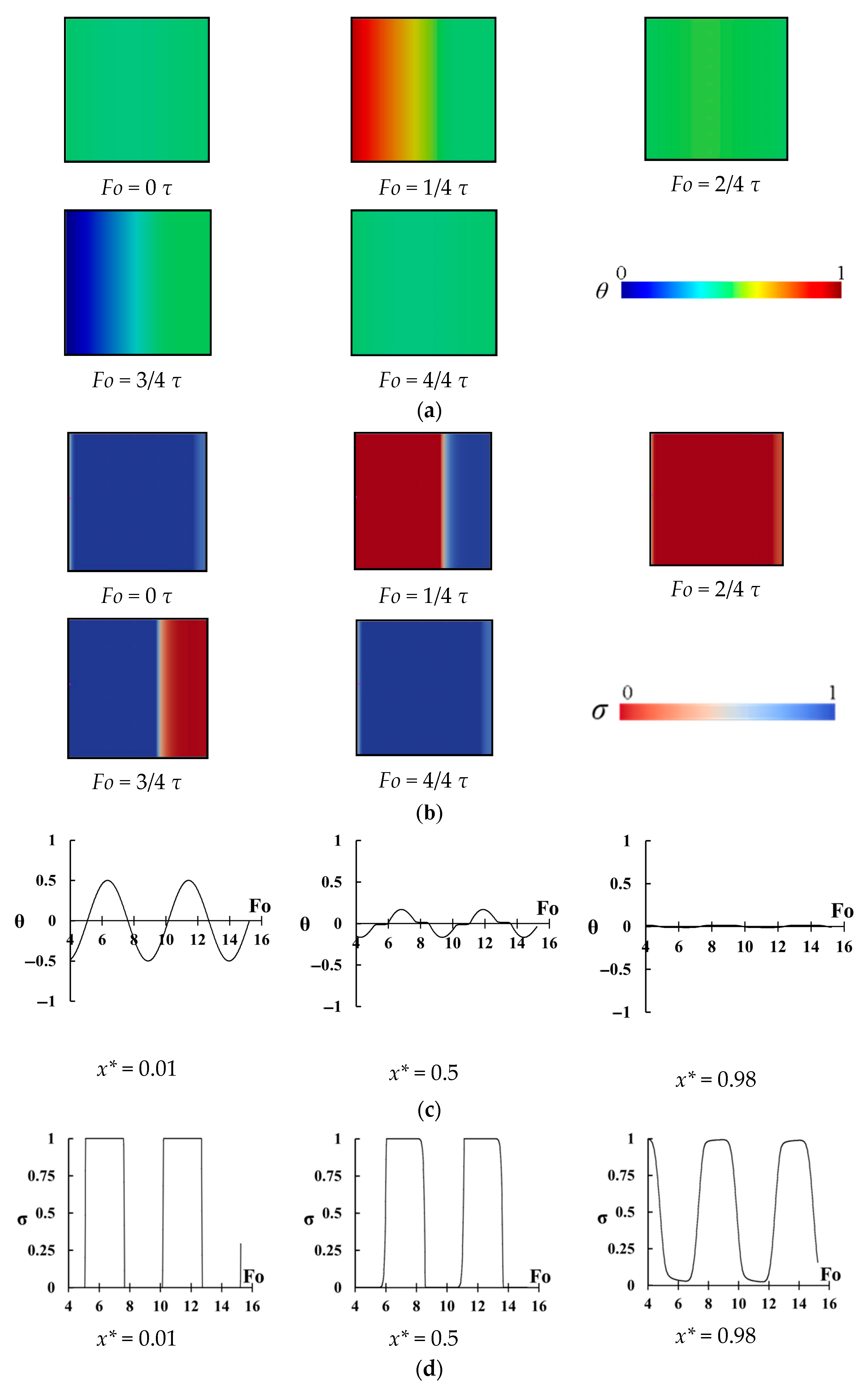
The same temperature distributions of
Figure 7 and
Figure 8 are shown in
Figure 9 but for
. The melting and freezing start from the left wall and approach to the right region. The difference between
Figure 7 and
Figure 8 with
Figure 9 is that it seems that PCM is completely melted or frozen on time in the right region. In
Figure 7, the melting and freezing of PCM are not completed and in
Figure 8 the melted PCM in the right region remains in the same phase for a long time and stores sensible heat. However, for
Figure 9, most of the heat in the right region is stored by latent heat, and almost no sensible heat is stored. The variation of temperature and melting fraction for three points of
prove this fact (
Figure 9c,d). A high-temperature change can be seen for the point of
, and this temperature variation considerably decreases for
, however, a complete solid/liquid phase change occurs in the right region since the temperature changes just inside the melting temperature region. Almost a full phase change can be seen in
Figure 9d for
.
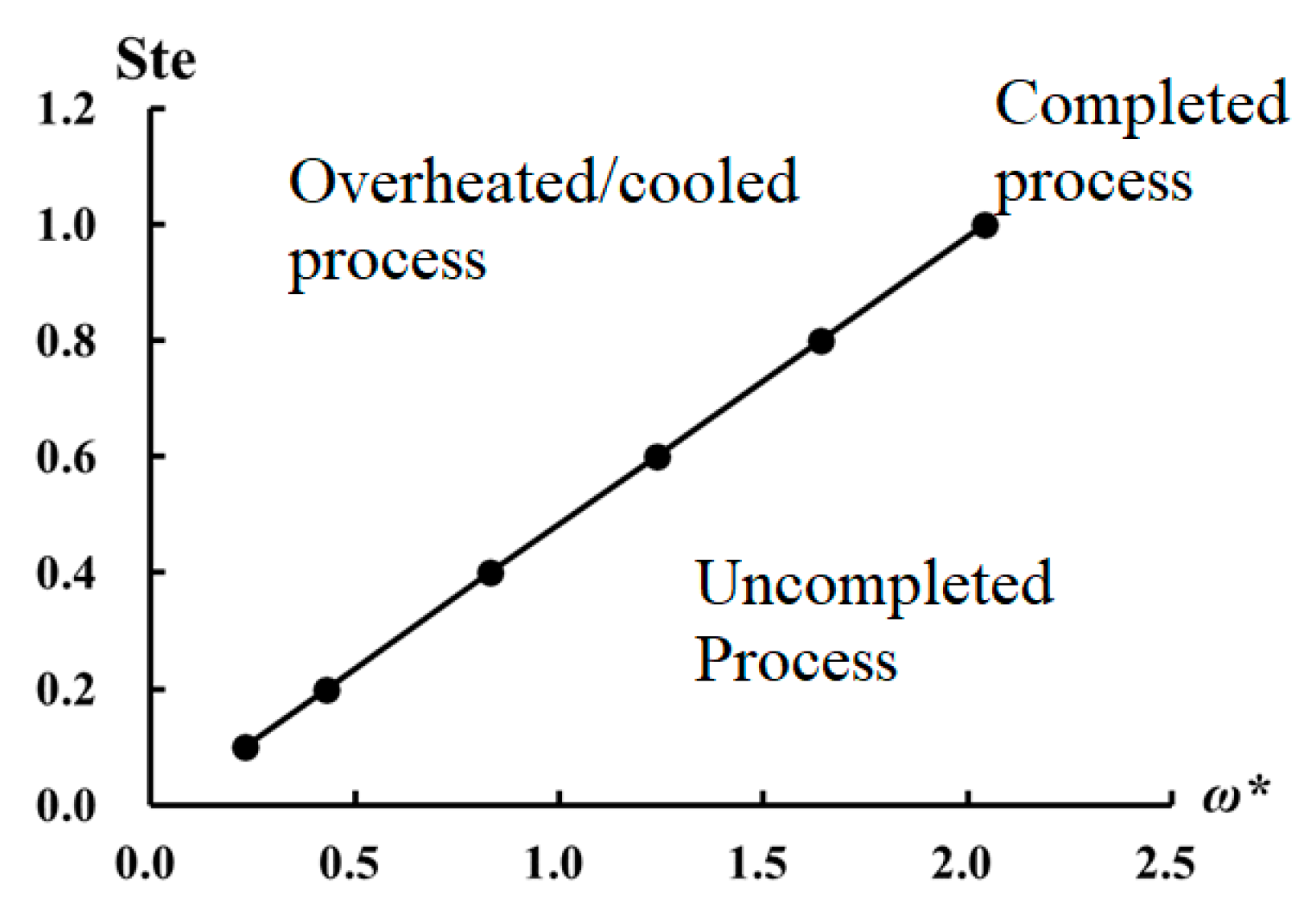
As it can be seen from
Figure 7,
Figure 8 and
Figure 9, based on the values of
and Ste number, there might be three regions as (a) the region in which the phase change in the right region (i.e., end of the cavity) does not occur completely, (b) the region in which the right region stays in the same phase for a long time and (c) the region in which the phase change occurs in the entire cavity with minimum temperature change. In this study, a chart in terms of dimensionless frequency and Ste number is established to predict the character of the phase change in the cavity without doing any computational calculation, and it is shown in
Figure 10. The
x-axis is dimensionless frequency while
y-axis shows Ste number. The plotted line divides the chart into three regions. The top region is called the overheated/cooled process, referring to a process that the entire region of the cavity is overheated or subcooled. The bottom region is called the uncompleted process and the right region of the cavity is inactive and just occupies space and increases the weight. The operation conditions on the curve show a cycle in which the right region of the cavity is under complete solid/liquid phase change without any overheating or subcooling.
Figure 10 yields three important points,
- (a)
A thermal designer should calculate values of
and Ste number and find operation points on
Figure 10. She/he should avoid operation in the uncompleted process region since some parts of the cavity are inactive and do not play any role in thermal storage;
- (b)
For the points which are on the line (completed process), most of the thermal storage occurs by latent heat while for the system operating in the overheated/cooled process, in addition to latent heat, sensible thermal storage also plays an important role;
- (c)
In many cases, Stefan number is accepted as a dimensionless number used to decide the role of latent heat in thermal storage. For instance, for the low values of Stefan number, the role of latent thermal storage is significant while high Stefan numbers of sensible thermal storage gain importance.
Figure 10 shows that if a periodical temperature change exists at a wall of a thermal storage cavity, in addition to Stefan number, dimensionless frequency should be taken into account. For instance, one may think that sensible heat storage for a cavity with Ste = 1 is significant, however our results show that for Ste = 1 and
, most of the heat is stored by latent heat rather than sensible thermal storage.
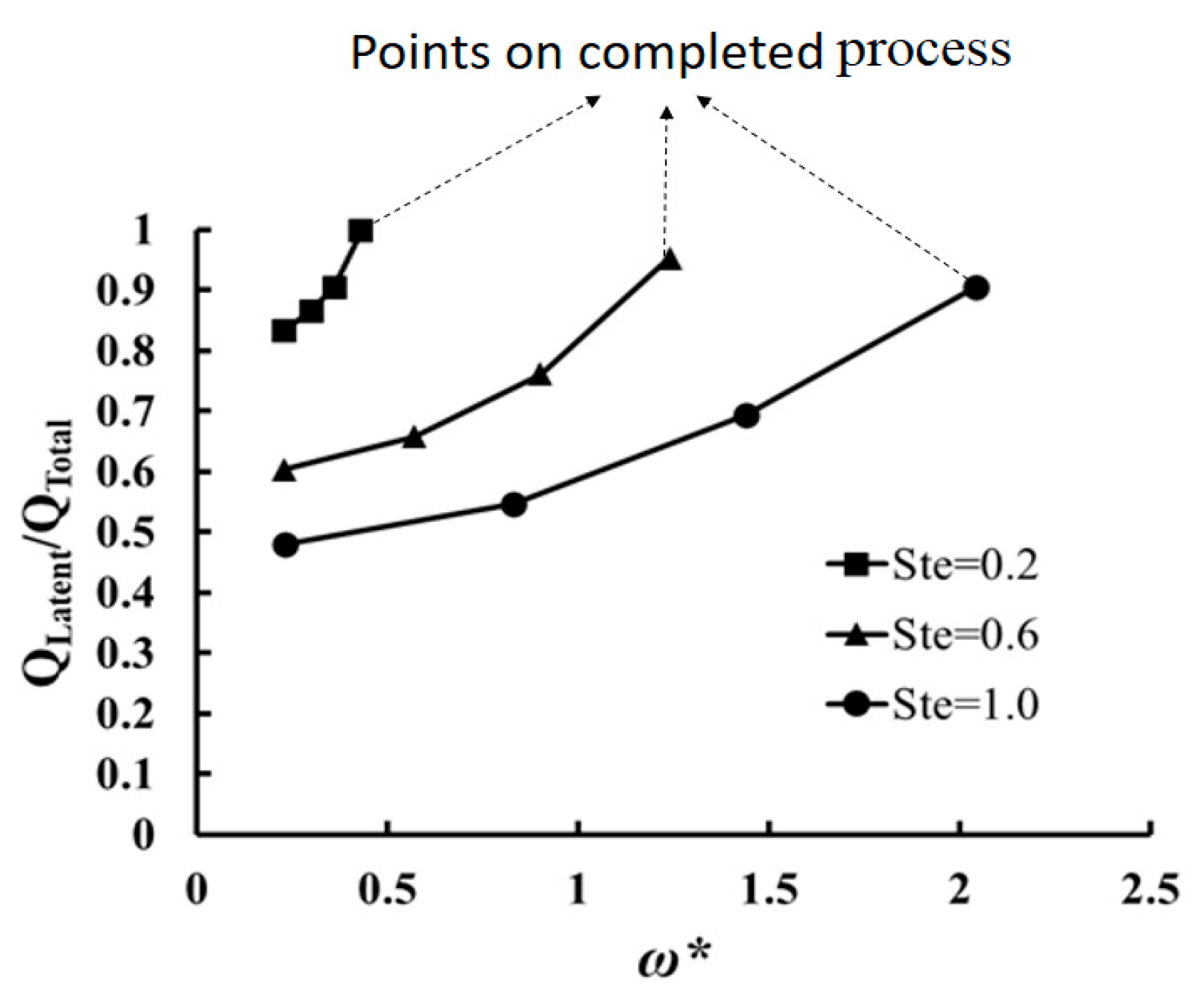
The change of percentage of latent heat in the stored thermal energy (i.e., as the ratio of latent heat storage) with dimensionless frequency for the region of overheated/cooled process is calculated for three Ste numbers as 0.2, 0.6, and 1.0 and shown in
Figure 11. The value of
changes between 0 and 1.
refers to 100% sensible heat storage while
= 1 shows a process only with latent heat storage. The value of
for the completed process is also calculated and shown. This diagram shows that a) the possibility of latent thermal storage even for a process with a high Stefan number (for instance Ste = 1 and
) exists, but in general, the effect of latent heat on thermal storage is greater than sensible storage for the process with small Stefan number (e.g., Ste < 0.4).
Figure 11 shows that by decreasing
the ratio of latent heat storage decreases. For instance, for Ste = 0.6, 95% of the stored heat is latent heat when
but by reducing the dimensionless frequency to 0.23, the weight of latent heat in the process decreases to 60%. By decreasing of
, the temperature of the cavity highly increases or decreases as is shown in
Figure 8. PCM are used in a thermal storage process due to their latent heat. However, for the process with a high value of Stefan number (Ste = 1) and low dimensionless frequency (such as
), the role of latent heat is 48%. Therefore, in those processes, the use of proper sensible thermal storage materials may increase the thermal storage performance. The reason for low latent thermal storage is not Stefan number and this effect is due to the low value of dimensionless frequency (i.e., long period).


