Article

Feasibility Evaluation on Elimination of DC Filters for Line-Commutated Converter-Based High-Voltage Direct Current Projects in New Situations

Department of Electrical Engineering, Zhejiang University, Hangzhou 310027, China
*
Author to whom correspondence should be addressed.
Energies 2021, 14(18), 5770; https://doi.org/10.3390/en14185770
Submission received: 25 July 2021 / Revised: 30 August 2021 / Accepted: 10 September 2021 / Published: 13 September 2021

Abstract

:
The line-commutated converter (LCC)-based high voltage direct current (HVDC) technology has been widely applied on long-distance and bulk-capacity power transmission occasions. Due to the terrible interferences in the vicinity of communication lines, DC filters (DCFs) are always installed to mitigate the interferences within acceptable levels for almost all in-service overhead line transmission LCC-HVDC schemes. With the rapid development of the communication technology, however, the anti-interference capability of the telephone system has been remarkably improved. Thus, the original purpose of employing DCFs has been virtually absent, and the necessity of the DCFs shall be re-evaluated in sufficient depth not only for new LCC-HVDC projects, but also in the case of refurbishment of older projects. To demonstrate this constructive topic, this paper carries out a commercial ±800 kV/8000 MW LCC-HVDC project as an illustrative example to analyze and discuss those crucial aspects, which may influence the LCC-HVDC stable operation and reliability after removing the DCFs. Then, the paper studies the harmonic voltage/current stresses of the DC equipment, the DC loop low-order harmonic resonances, and the overvoltage under the switching surge and lightning stroke. Finally, it is concluded that the DCF elimination mainly affects the harmonic steady-state stresses of the DC equipment, but has little influence on the transient stresses. For the refurbishment of older projects, the evaluation on the cost between the DCFs’ maintenance cost and the equipment modification is needed for the DCFs’ elimination. For new LCC-HVDC projects, the DCFs’ elimination or at least simplification may be a more economical and attractive alternative, thereby reducing the footprint and cost.

1. Introduction

To fulfill the ever-growing energy demand, high-voltage direct current (HVDC) transmission technology has drawn an indispensable role on long-distance and bulk-capacity power transmission occasions, notably the vast territory areas where the energy sources and load demands are distributed unevenly [1,2,3,4,5]. Up to now, over 150 point-to-point line-commutated converter (LCC)-based HVDC projects have been in service worldwide due to its high technology maturity, small operation loss, low investment and maintenance cost [6,7,8]. Especially in China, nearly 20 LCC-based ultra-HVDC (LCC-UHVDC) projects with operational DC voltage from ±800 kV to ±1100 kV are already commissioned with approximately 1000 km to 3000 km distances [9,10,11,12].
Due to the LCC nonlinear switching actions, quantities of harmonic voltages are generated at the converter terminals, causing harmonic currents flowing into the DC lines [13,14]. If the DC lines are placed in the vicinity of communication lines, the harmonic currents will produce terrible interferences in adjacent communication lines through inductive coupling [15,16,17]. Thus, for almost all in-service overhead line transmission LCC-HVDC schemes, the DC filters (DCFs) are always installed to mitigate the interferences within acceptable levels [18,19]. As shown in Figure 1, the DCF circuits are usually arranged in parallel between the DC pole busbar and the neutral bus. Contrarily, the back-to-back and the cable transmission LCC-HVDC schemes do not require DCFs [20].
Though the performance of the DCFs in mitigating the interferences is highly effective, the equipment cost is high, and the design procedure is time-consuming. The occupational area is generally largest of all DC-side equipment [20]. The high voltage (HV) capacitor is the most cost-intensive element, as it has to require numerous series capacitor units to withstand the entire pole-to-neutral DC voltage [10]. These series units with internal grading resistors form a super slim HV capacitor tower, which is very vulnerable to wind and earthquake [21]. Especially for the voltage levels of 800 kV and above, such tall towers are more difficult to manufacture and maintain, and the corresponding expenditure is inevitably increased. Meanwhile, the DCF design is an iterative procedure of trial and error, converging to a near-optimal solution. In order to fulfill the desirable performance criteria and determine the maximum steady-state stresses of all individual DCF elements, extensive calculations for all possible specified operation conditions must be taken into account 19. Further, any element in DCFs inevitably suffers some risk of failure, consequently increasing the failure rate and reducing the reliability of the entire LCC-HVDC system.
In the early stage of HVDC development, the interference in nearby communication lines is a serious problem, as the open-wire telephone lines are extensively applied over the world, which are particularly sensitive to harmonic induction [22]. Thus, DCFs are absolutely necessary at that time. Since the 1990s, however, the communication technology has been rapidly developed, and the anti-interference capability of the telephone system has been remarkably improved. The digital communication network with optical fibers as main frame has a particularly high penetration, in which the optical fiber is the insulation medium and can completely eliminate all harmonic induction. Based on a survey [23] in China, the vast majority of the obsolete telephone lines have been superseded, and only part of residual lines may still be disturbed. Compared with installing the costly DCFs, it is a more economical alternative to modify those disturbed telephone lines.
With the state-of-the-art communication technology, the original purpose of employing DCFs to suppress the inductive interference has been virtually absent. Thus, with a potential large cost reduction, the necessity of the DCFs shall be re-evaluated in sufficient depth not only for new LCC-HVDC projects, but also in the case of refurbishment of older projects.
For the DCFs, the existing literatures almost focus on the design, which are old, and may be un-adapted for new situations. To the best of the knowledge of the authors, up till now, only [21] proposed this topic, while no related literature has presented the comprehensive analysis and argument. To demonstrate this constructive question, this paper carries out a commercial LCC-UHVDC project as an illustrative example. Then, some crucial aspects, which may impact the LCC-UHVDC stable operation and reliability after removing the DCFs, are meticulously analyzed and discussed. The aspects comprise the harmonic steady-state stresses on DC-side apparatus, the low-order harmonic resonances of the entire DC loop, and the overvoltage protection levels of the DC-side surge arresters. The contributions of this paper are summarized as follows:
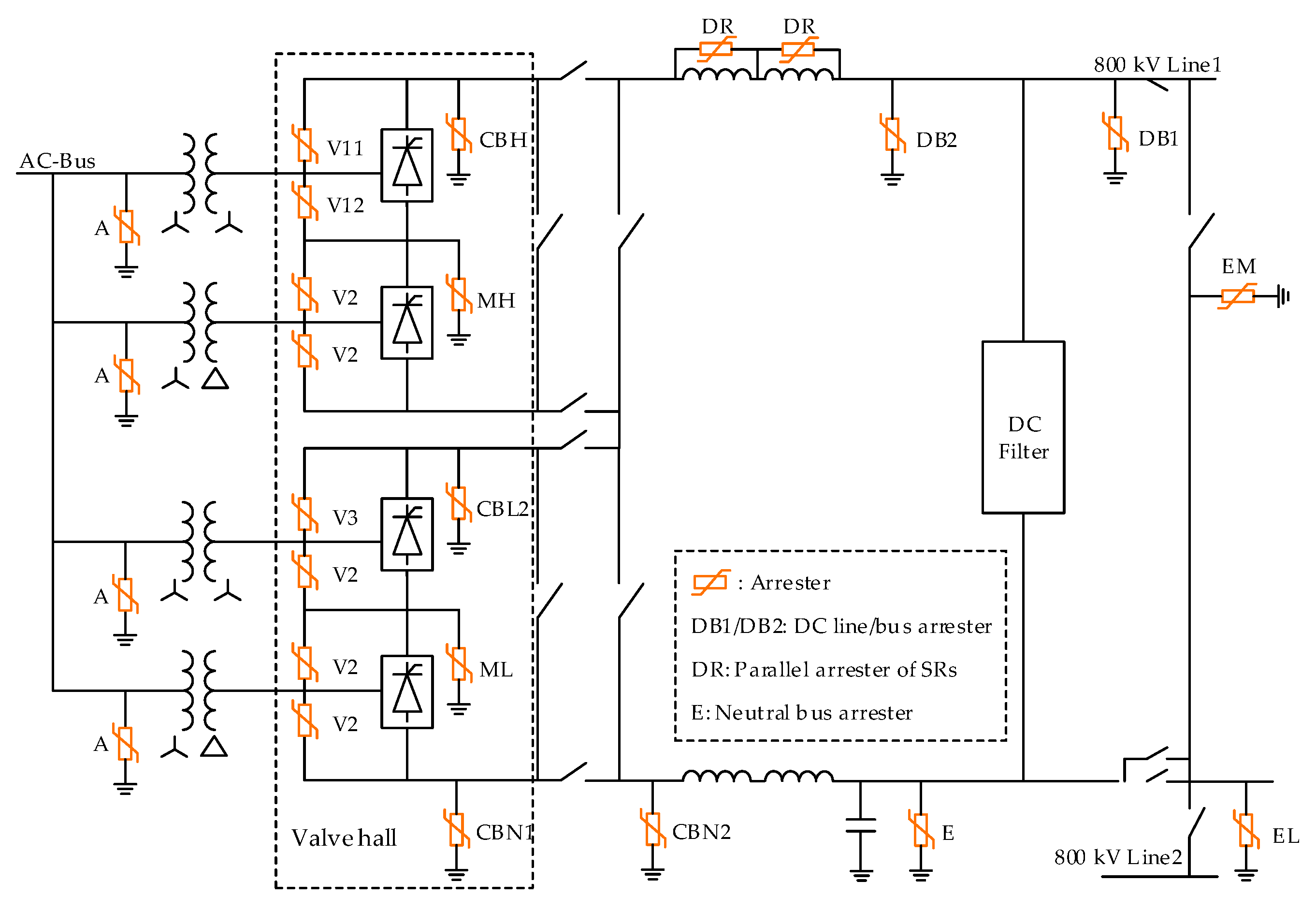
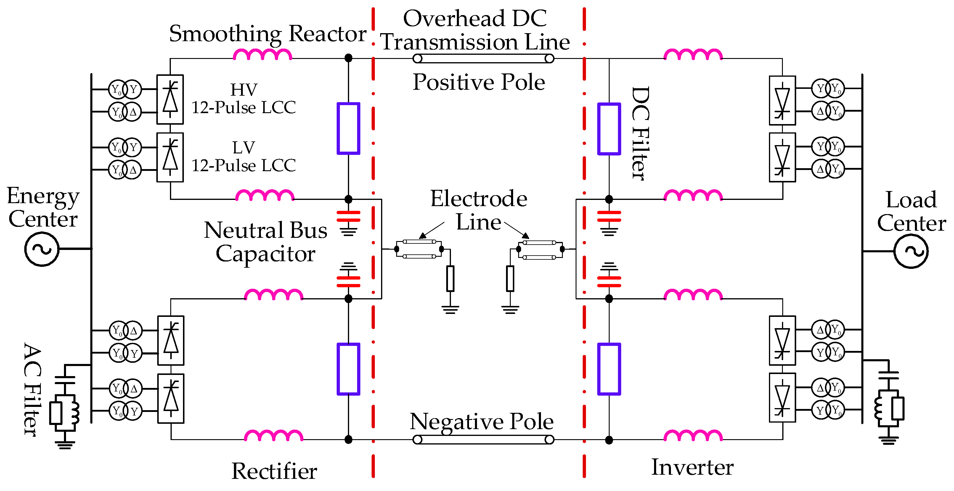
  • To scientifically demonstrate the feasibility on the elimination of DC filters, a ±800 kV/8000 MW in-service LCC-UHVDC project is taken as a representative example, including the DC loop parameters and surge arresters’ arrangement.
  • In order to comprehensively research the impacts on the harmonic steady-state stresses and the transient stress on DC-side apparatus after removing the DCFs, the mature technologies (i.e., the standard steady-state frequency-domain analysis, and the PSCAD/EMTDC simulation) are adopted.
  • Suggestions are put forward for the DCFs’ configuration or refurbishment of LCC-HVDC project in China, which could be a reference for similar LCC-HVDC projects in the world.
The outline of this paper is organized as follows. Section 2 describes the development of communication technology. Section 3 introduces the HVDC system modeling and the solution for the steady-state DC-side circuit. In Section 4, the DC loop parameters and surge arresters’ arrangement of the project are presented. Section 5 analyzes the steady harmonic stresses. Section 6 calculates the switching and lightning overvoltage. Section 7 dawns the conclusion.

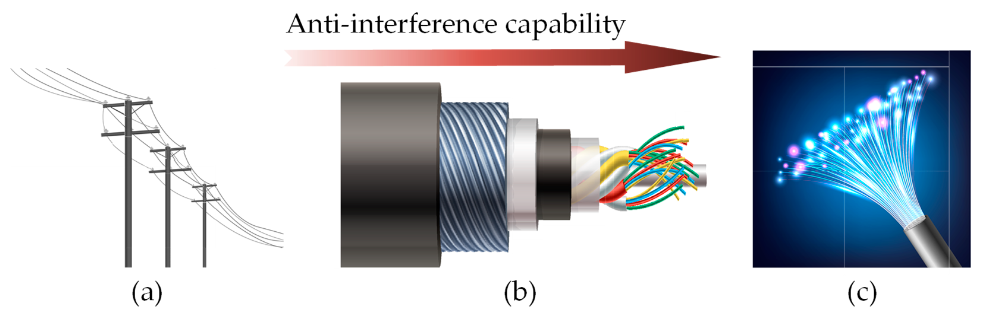
2. Development of Communication Technology

Since the 1990s, the communication systems have changed beyond recognition. As depicted in Figure 2, through the upgrade from overhead open-wire lines, shielded aerial or buried cables to the optical fibers, the anti-interference capability of the communication lines has been remarkably improved. Among them, the overhead open-wire lines are particularly vulnerable to harmonic induction, whereas the optical fibers are absolutely immune to induced noise [24]. With the optical fibers as main frame, the digital communication network has a particularly high penetration all over the world. Besides, the mobile telephony is now ubiquitous, which is also immune to noise.
Since the overhead HVDC lines are mostly constructed in the rural areas and suburbs, specific concerns should be paid to the village communication lines, the railway signal cables and the military cables. According to a survey [23] in China, the fiber to the premises (FTTP) has been implemented in most villages, where the vast majority of the obsolete telephone lines have been superseded, and only a fraction of residual lines may still be disturbed. The railway signal cables are all armored and shielded with alumina sheath, leading to a high degree of immunity from interference. All military cables are paved with optical fibers. Thus, in the case of refurbishment of older projects, especially for new LCC-HVDC projects, compared with installing the costly DCFs, it may be a more economical and attractive alternative to modify those disturbed lines.

3. HVDC System Modeling

3.1. Subsection

As presented in Figure 1, the DC-side harmonic filtering system includes the DCF, the smoothing reactor (SR) and the neutral bus capacitor (NBC). Among them, the DCF has no other function than to mitigate the interference by shunting several prominent large-amplitude harmonic currents to the station neutral bus or ground through the low-impedance circuits, thus having the possibility of eliminating the DCF.
The DCF circuits are usually installed in parallel between the DC busbar and the station neutral bus or ground. They are specifically designed to mitigate the harmonic currents flowing in the overhead DC transmission line and the electrode line. In practice, the double- or triple-tuned passive filters with a shared HV capacitor are mostly employed due to the technical and economical superiorities, whose algorithm for parameters could be referred to as in [25]. In some projects, the blocking filters series in the neutral bus are also required to mitigate low-order harmonic resonances.
As a key equipment in HVDC projects, besides the harmonic suppression capability, the SR has the following main functions: (1) avoid the intermittent current and attendant overvoltage in the light load range; (2) limit the rise rate of fault current in the event of AC short-circuit faults or DC line faults; (3) protect the converter from lightning strikes on the DC line; (4) suppress the low-order harmonic resonances. For the voltage levels of 800 kV and above, the SR is often split equally in pole bus and station neutral bus, owing to the limitations of insulation and manufacture [11].
The NBC is installed in parallel between the station neutral bus and ground, which is a large capacitor in the range of 10~30 μF. It provides a nearby low-impedance in-station return path for the triple harmonic currents flowing through the stray capacitance, and significantly inhibits these currents flowing into the electrode line. It can also buffer over-voltage caused by a lightning strike on the electrode line.

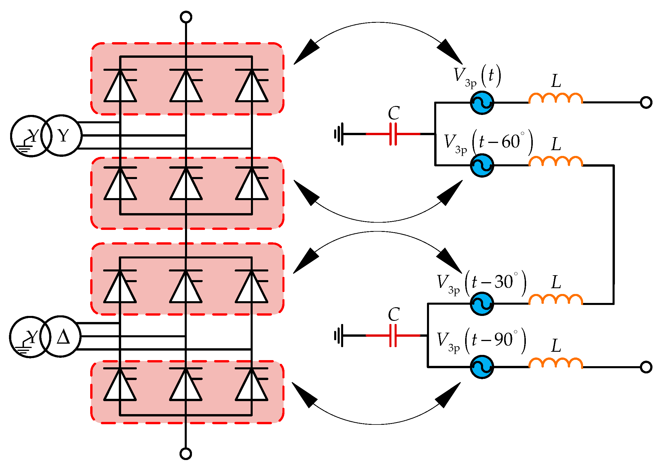
3.2. Harmonic Voltage Source Model

The three-pulse harmonic voltage source model is widely adopted to analyze the harmonic behavior on the DC side, as it can represent explicitly all triple harmonic voltages and the leakage paths formed by the stray capacitance from converter transformer windings and bushings to ground [14]. As shown in Figure 3, a twelve-pulse bridge comprises two six-pulse bridges with a 30° phase displacement, and is equivalent to four series-connected three-pulse harmonic voltage sources with internal inductances.
In Figure 3, L is one-half of the time-average value of the commutating inductance; C is the stray capacitance to ground in the bridge, and its typical value is 10~20 nF; V3p(t), V3p(t − 60°), V3p(t − 30°), and V3p(t − 90°) are the equivalent harmonic voltage sources of four three-pulse half bridges, respectively. Considering the effect of various asymmetries in the valve firing angle, the commutation reactor, and the deviation of the winding parameters and AC system imbalances, the piecewise linear analysis approach in [15] is adopted to calculate the three-pulse harmonic voltages.
Obviously, the harmonic voltages vary with the operation conditions. To ascertain the worst-case harmonics and save the computational efforts, the worst non-consistent set is adopted in calculations 19. First, under a specific operating mode (e.g., bipolar, nominal DC voltage, etc.), considering the asymmetries, several harmonic sets for different operating points are calculated. Here, the DC power is increased from minimum (0.1 p.u.) to maximum (1.2 p.u.) at the step of a certain percentage (5% or 10%) of the rated DC power. Then, the worst set of harmonics is formed by selecting the worst individual order harmonic voltage among the multiple harmonic sets in the full power range, namely the worst non-consistent set. Finally, by repeating the above two steps, the worst non-consistent sets of other possible operating modes are obtained. This approach is somewhat pessimistic, since the worst individual harmonic does not occur simultaneously at a certain operating point.

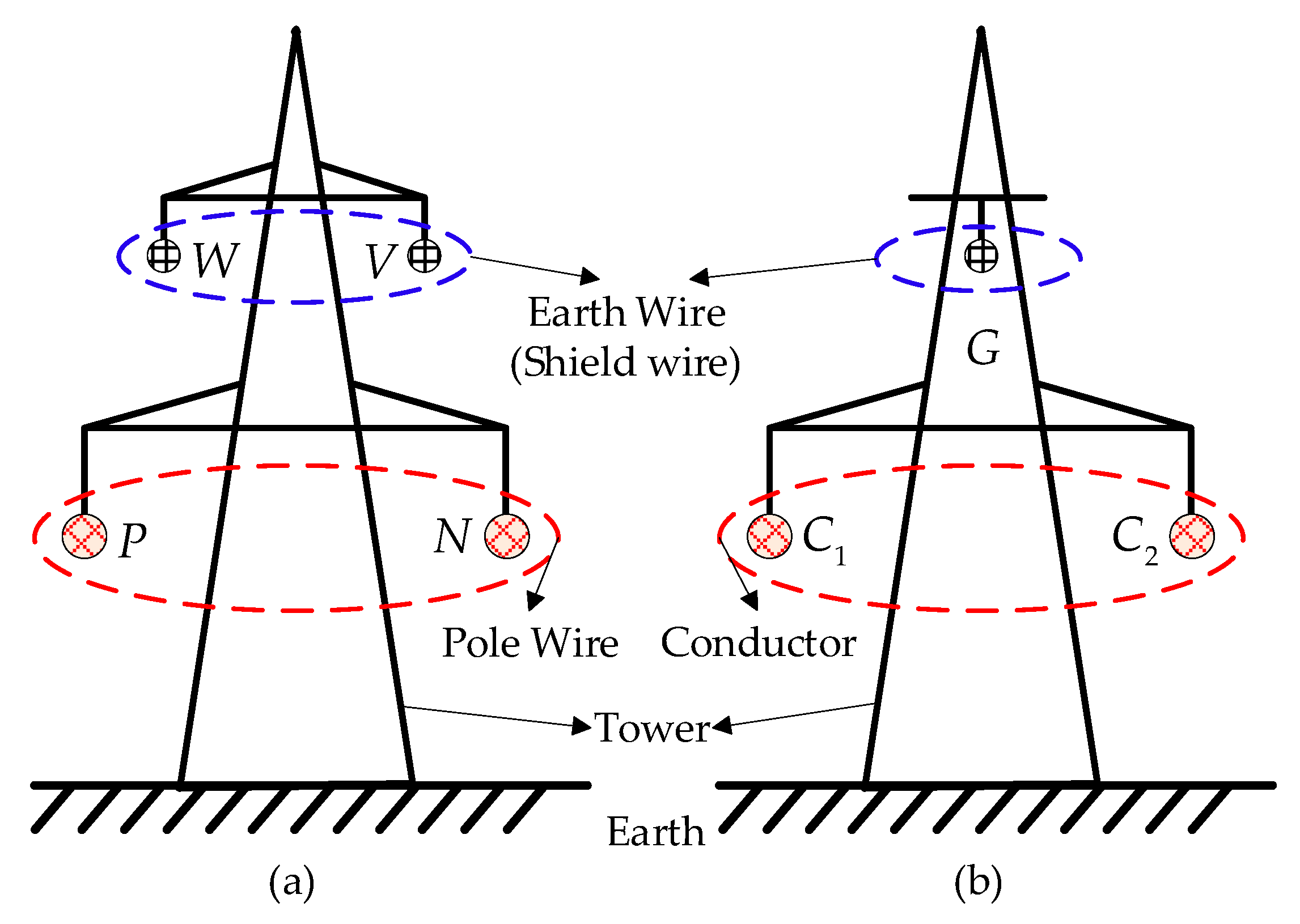
3.3. DC Transmission Line Model

In practical projects, the structures of the overhead DC transmission line and electrode line are shown in Figure 4, respectively. The overhead DC transmission line consists of four coupled wires physically in parallel on the same tower, or three coupled wires for the electrode line. In the majority of line installations, the earth wires are used as shield wires and are solidly earthed at both the sending and receiving ends. As a simplification, the earth wires are not shown in Figure 1.
In the analysis of the DC-side harmonic behavior, the non-linear influences of the earth and the conductors with respect to frequency are particularly important for long transmission lines. Accounted for the ground resistivity and skin-effect, the distributed parameters of lines are calculated by using Carson’s equations [26], which are expressed with the frequency-dependent series impedance matrices Z and shunt admittance matrices Y per unit length. The parameters necessary for distributed-parameter calculation comprise all wires’ data (i.e., type, size, geometry, resistivity), tower and span geometry, sag, and ground resistivity.
When solving the DC-side circuit, the coupled multi-phase transmission line is regarded as a multi-node element. Based on the phase-mode transformation, the nodal admittance matrix of the line Yl is expressed as [27]:
{ [ I S I R ] = Y l [ U S U R ] = [ Y s Y m Y m Y s ] [ U S U R ] Y s = Z 1 T u Γ c t h ( Γ l ) T u 1 Y m = Z 1 T u Γ c s c h ( Γ l ) T u 1 Γ = Λ 1 / 2 = ( T u 1 Z Y T u ) 1 / 2
where, US, UR, IS, and IR are the voltage and current vectors at the sending end and the receiving end of lines, respectively; Ys and Ym are the self- and mutual-admittance matrices; Γ is the propagation matrix; Λ is the eigenvalues matrix of (ZY), and Tu is the transformation matrix composed of eigenvectors corresponding to Λ; l is the length of the transmission line.

3.4. Solution for the DC-Side Circuit

The equivalent DC-side model for harmonic behavior analysis is formed as in Figure 5. The model is a linear but frequency-dependent circuit, which synthesizes the three-pulse harmonic voltage sources, the DC-side harmonic filtering system, the overhead DC transmission line, the electrode lines and the ground electrode resistances.
Based on the standard steady-state frequency-domain analysis technique, the DC-side circuit can be solved with the nodal voltage analysis method, namely, I = YdcU. Here, I is the injection current vector; U is the nodal voltage vector; Ydc is the nodal admittance matrix of the entire DC-side circuit.
The solution for the DC-side circuit mainly includes five steps, as follows:
Step (1).
Calculate the worst non-consistent sets of three-pulse harmonic voltage sources with the piecewise linear analysis approach derived in [15].
Step (2).
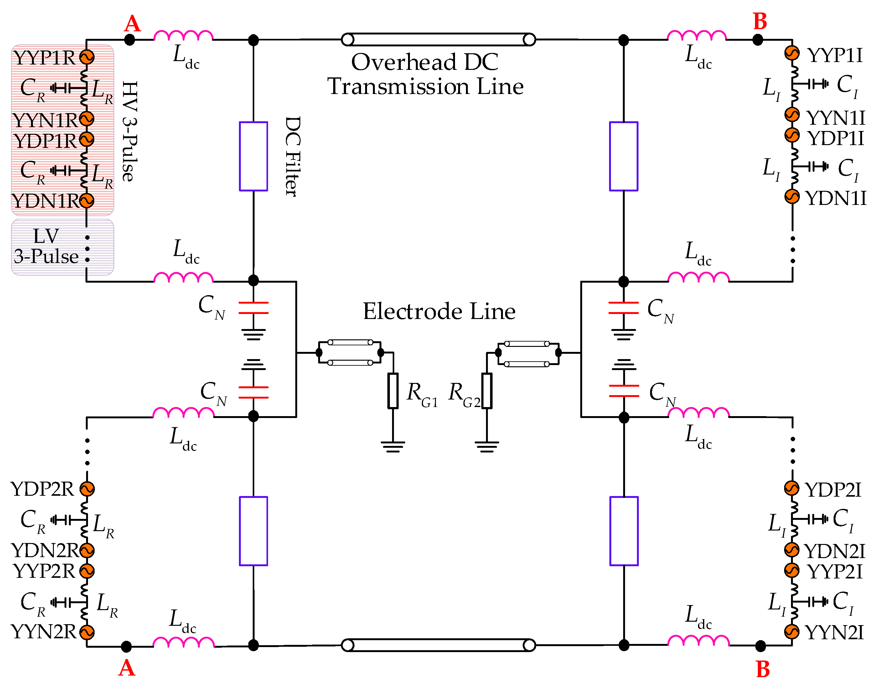
Form the nodal admittance matrix Ydc(n) at nth-order harmonic. First, calculate the nodal admittance matrix of lines Yl(n) in (1), including the DC transmission line and the electrode lines. Then, insert the Yl(n) into Ydc(n) as multi-node elements. Finally, Ydc(n) is constructed by adding other elements in Figure 5 one by one.
Step (3).
Solve the entire DC circuit. First, suppose that the three-pulse sources at the rectifier act alone and the sources at the inverter are set to zero, the injection current vector I(n, 1) is calculated with the Norton equivalent. Second, the nodal voltage vector U(n, 1) is obtained with the nodal voltage analysis method. Then, repeat the similar process, the voltage vector U(n, 2) excited solely by the three-pulse sources at the inverter is acquired. Finally, the harmonic voltages Ue(n, i) that the elements bear and the harmonic currents Ie(n, i) flowing in elements are calculated. Here, i is 1 or 2, which denotes the rectifier or the inverter.
Step (4).
Calculate the steady-state stresses of elements. Synthesized with all individual harmonics, the steady state stresses of the capacitors are expressed as in:
{ U C = i = 1 i = 2 n = 1 n = N U e ( n , i ) I C = i = 1 i = 2 n = 1 n = N I e ( n , i )
where N is the maximum harmonic order. The voltage stress expression of the reactors UL are the same as that of the capacitor, while the current stress of the reactors are calculated by the root sum of squares (RSS) method as:
I L = i = 1 i = 2 n = 1 n = N I e 2 ( n , i )
Step (5).
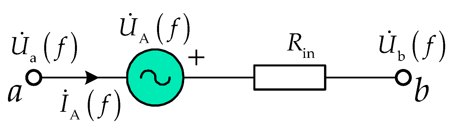
Calculate the DC-loop impedance. Firstly, insert two identical test voltage sources at point A in Figure 5, whose schematics are shown in Figure 6. Here, U ˙ A ( f ) is the voltage phasor of the inserted voltage source at the specified frequency f, Rin is the internal resistance; I ˙ A ( f ) is the current phasor flowing through point A; U ˙ a ( f ) and U ˙ b ( f ) are the voltage phasors at point a and point b, respectively.
Then, with the passive part in Figure 5 and the inserted test voltage sources, U ˙ a ( f ) and U ˙ b ( f ) are calculated by using the method similar to Step (2) and Step (3). Finally, the DC-loop impedance from the rectifier side Zdc_R(f) is derived as:
Z dc _ R ( f ) = U ˙ A ( f ) I ˙ A ( f ) = U ˙ A ( f ) R in U ˙ b ( f ) U ˙ a ( f ) + U ˙ A ( f )

4. Parameters of the Test System

In this paper, a ±800 kV/8000 MW LCC-UHVDC project is taken as an illustrative example. As shown in Figure 1, each pole consists of two 12-pulse converters connected in series, i.e., a HV converter, and a low-voltage (LV) converter. The main parameters of the converter stations are listed in Table 1.

4.1. Subsection

The operating modes include bipolar or monopolar, and full or reduced (70%) DC voltage operation. The asymmetries are as follows: (1) the negative-sequence AC voltage of the 1.1% fundamental positive sequence is used, where the phase angle is assumed to be uniformly and randomly distributed between 0° and 360°; (2) the imbalances in firing angle between the valves in a 12-pulse converter are assumed to have a standard deviation of 0.0184°; (3) the phase reactance deviations from the mean values are assumed to be normally distributed with a standard deviation of 0.7%; (4) other factors are also considered, such as background harmonic voltages [21]. For the limited space, only the worst non-consistent set of bipolar and full DC voltage operation are listed in Table 2. Here, the maximum harmonic order N is 50, and the harmonic voltages of LV converter are equal to those of the HV converter.

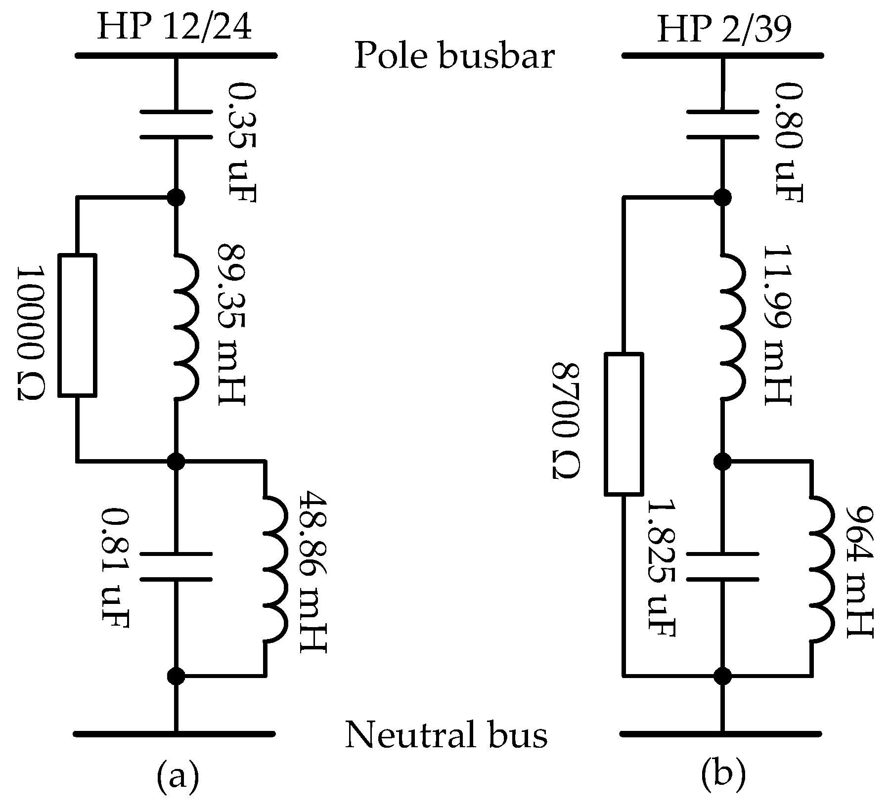
4.2. DC-Side Harmonic Filtering System

Two identical SRs with nominal reactance of 75 mH are installed on both DC 800 kV pole busbar and neutral bus at each pole in each station, namely 150 mH. The NBCs at the rectifier and inverter are 17 μF and 15 μF, respectively. The DCFs’ configuration are identical for each pole in each station. The schematics and parameters of two double-tuned DCFs are shown in Figure 7, respectively. In order to avoid the fundamental frequency resonance, the blocking filters are placed in series at the neutral bus in both poles of the rectifier.

4.3. DC Transmission Lines

Table 3 elaborates the parameters of the overhead DC lines and the electrode lines. Here, to approximate the varying earth resistivity, the overhead DC lines are split into two sections.

4.4. Surge Arrester Scheme

The surge arrester configuration of the studied project is illustrated as in Figure 8. Here, the specific description of each arrester could be referred to as in [28], and will not be repeated here in full depth.
On the basis of the arrangement principles of arresters and arrester stresses for different events, the stresses of the arresters (i.e., DB1/DB2, DR, and E) are most likely to be affected after removing the DCFs. Table 4 shows the basic parameters and protection levels for the relative arresters [29].

5. Study on Steady Stress

Based on the calculation procedure described in Section 3.4, the steady harmonic stresses for the DC-side circuit are solved. For the steady harmonic stress without the DCFs, some equipment which may be impacted are researched, including the NBC, the SR at the DC pole bus, the voltage at the DC line inlet, and DC-side low-frequency impedance. Three operation modes are considered as follows: (1) bipolar and full DC voltage (BIF); (2) monopolar with earth return and full DC voltage (MGF); (3) monopolar with earth return and reduced DC voltage (MGR).

5.1. NBC

As listed in Table 5, the harmonic voltage stresses for the NBC are increased by only about 1.0 kV after removing the DCFs. Under normal operation, the NBC withstands the tiny DC voltage. Thus, after removing the DCFs, the upgrading and reconstruction for the NBC is hardly necessary.

5.2. SR

Before and after eliminating the DCFs, the harmonic current stresses for the SR are presented in Table 6. This is an interesting result, that is, the harmonic current stresses for the SR are unexpectedly diminished. The reason is that the DCF branches supply a nearby low-impedance circuit for specific tuning harmonic currents (i.e., 2nd, 12th, 24th, etc.) to flow into the neutral bus instead of the pole bus. The DCF branch shunt a majority of those harmonic currents, while the currents at the line side of the DCFs are decreased. In other words, compared to the DC circuit without the DCFs, the DC loop impedance with the DCFs is relatively smaller at the specific tuning frequencies, thus resulting in larger currents.
Thereby, the DCFs’ removal has barely an effect on the SR, whereas the currents flowing in the DC switching devices and DC current transformer (CTs) at the line side of the DCFs are adversely enlarged, resulting in increase of losses.

5.3. Voltage at the DC Line Inlet

Before and after canceling the DCFs, the harmonic voltage stresses at both ends of the positive pole DC line are exhibited as in Table 7. Without the DCFs, the harmonic voltage stresses at both ends of the DC line are evidently magnified, mainly dominated by the 2nd and 12th harmonics. It may accelerate the insulation aging, and shorten lifetime for the equipment near both ends of the pole DC line. At the same, the operating voltage for the arresters of DB1/DB2 are also enlarged.

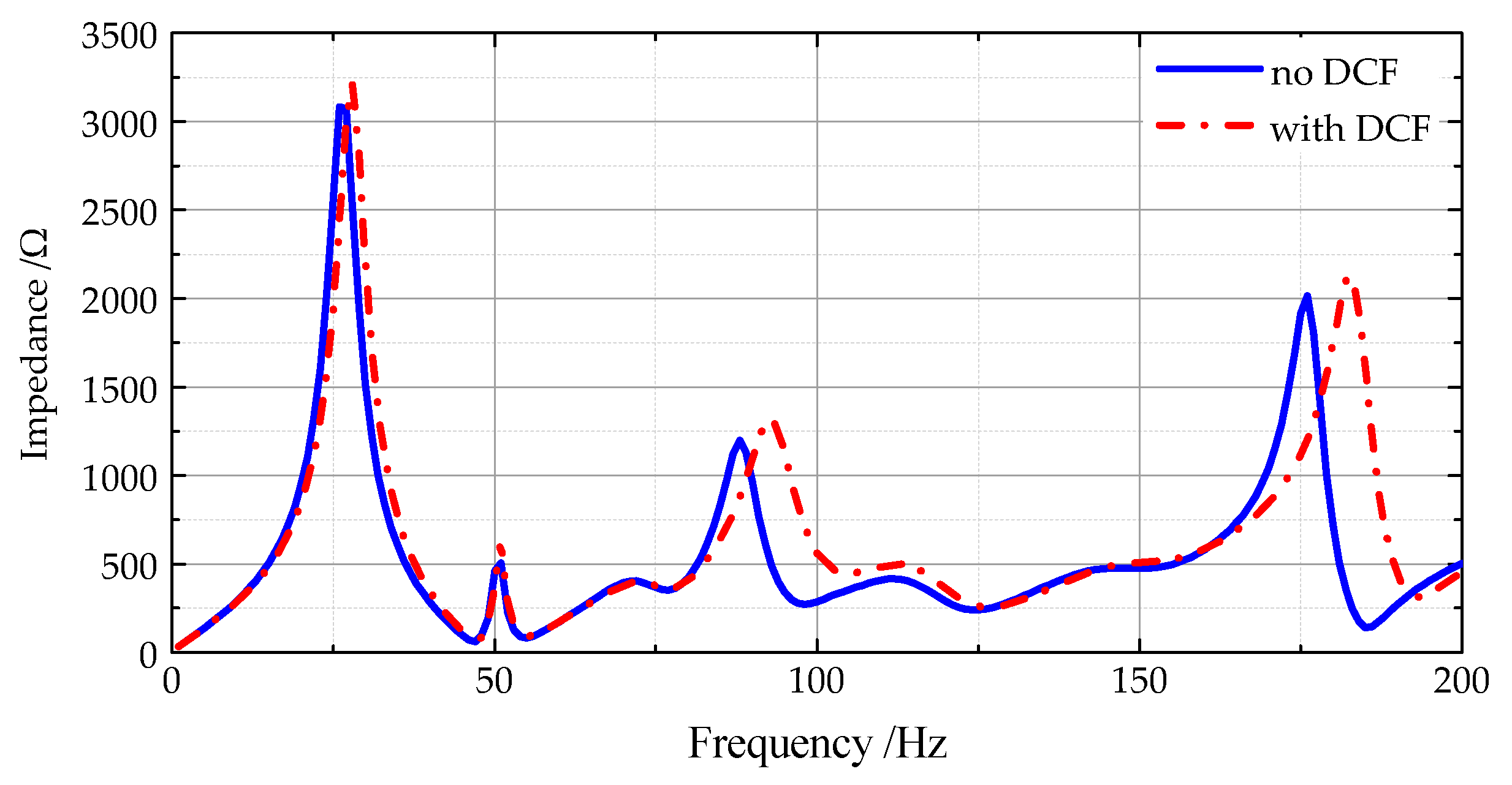
5.4. DC Loop Impedance

Due to the very large inductances and capacitances of both the LCC converters and the DC lines, resonances at the lower frequencies (generally fundamental and 2nd harmonics) are almost inevitable [21]. When the DC system resonance occurs, excessive harmonic currents and voltages may be generated, and can even damage the converter, the SR and other equipment.
Insert two identical 1.0 kV test voltage sources at point A in Figure 5, and then the DC loop impedances for bipolar mode are calculated and drawn in Figure 9. Here, the frequency f is ranged from 1 Hz to 200 Hz at the step of 1 Hz. It is observed that due to the blocking filter, the DC impedances at 50 Hz are amplified to about 500 Ω whether the DCFs are present or not. Without the DCFs, the DC impedance is reduced from 561.52 Ω to 287.55 Ω at 100 Hz. Hence, the DC system suffers the risk of the 2nd resonance.

5.5. Summary

Based on the research, in this Section, it is concluded that it has little effect on the NBC and SR after canceling DCFs. The voltage and current stresses are undesirably elevated for the DC-side apparatus at the line side of the DCFs, such as the DC line switch, CTs, and pole arresters (DB1/DB2). The elevated stresses will imply a higher operation loss, equipment voltage rating, insulation, and consequently, the increased expenditure for those affected devices. Since the existing LCC-UHVDC projects usually install the series fundamental blocking filters, no resonance will occur near 50 Hz, and the concern on resonance has shifted to 2nd harmonic resonance.
In the case of refurbishment of older projects, the evaluation on the cost between the DCFs’ maintenance cost and the equipment modification is needed for the question of whether DC filters are required. If the equipment modification cost is lower, the DCF removal is technically feasible, and vice versa. For new LCC-HVDC projects, the enhancement on voltage rating and insulation may be a more economical and attractive alternative than installing the extensive DCFs, thereby reducing the footprint and cost. At least, the DCF branch could be simplified to a 2/12 double-tuned DCF, where the 2nd tuning frequency is applied for the resonance suppression, and 12th for mitigating the prominent harmonic.

6. Study on Transient Stress

In this Section, the LCC-UHVDC electromagnetic transient model is benchmarked on the PSCAD/EMTDC to study the protection performance for the surge arresters listed in Table 4. The arrester configuration in Figure 8 is also accurately built.

6.1. Switching Overvoltage

The surge arrester is modeled with a non-linear resistance, and the Frequency Dependent (Phase) Line Model is employed. Other equipment uses PSCAD model, such as LCC converter and converter transformer. The events for the switching overvoltage study are listed in Table 8 [28].
The events are applied respectively, and the corresponding residual voltages of arresters are recorded as in Table 9. According to the simulation results, the residual voltages are always below the SIPL of the arresters, regardless of whether the DCFs are absent or not.

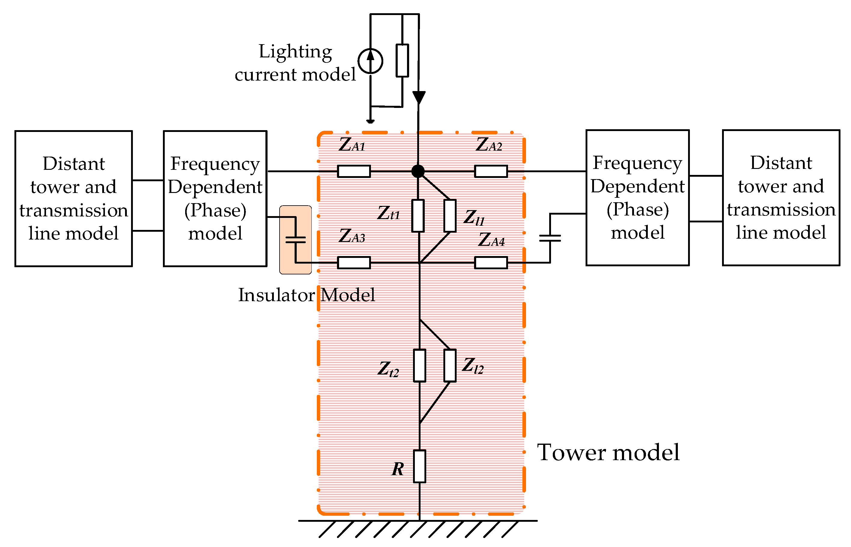
6.2. Lightning Overvoltage

All DC-side equipment is modeled with high-frequency model, including the LCC converter, the converter transformer, SR, surge arresters, and so on. As pictured in Figure 10, the tower is modeled with multi-segment multi-surge impedance model, and the Frequency Dependent (Phase) Line Model is adopted to connect the two sides of the tower [30]. The lightning current is simulated by double-exponential model. Both the counterstrike and the shielding failure are calculated with monopolar with earth return. The lightning current of the former is 260 kA with 300 Ω, and 24.46 kA/800 Ω for the latter.
Both the counterstrike and shielding failure are implemented, and the corresponding residual voltages of arresters are recorded as in Table 10. Before and after eliminating the DCFs, the residual voltages of lightning strikes are always lower than the LIPL of the arresters. It is noted that the residual voltage of the arrester E decreases drastically after canceling the DCFs, and the reason is that the lightning current path through the DCFs’ circuit to the neutral bus is obstructed after removing the DCFs.

6.3. Summary

Based on the overvoltage calculations, in this Section, it is concluded that the residual voltages are always below the protection levels of the arresters under both the switching surge and lightning stroke, regardless of whether the DCFs are absent or not. Thereby, under the consideration of DCFs’ elimination, little concern needs to be taken into the overvoltage and insulation co-ordination studies.

7. Conclusions

This paper first meticulously researches and evaluates the question on elimination of DC filters for LCC-HVDC projects in new situations. To demonstrate this constructive question, this paper carries out a commercial ±800 kV/8000 MW LCC-UHVDC project as an illustrative example. Then, based on the standard steady-state frequency-domain analysis and the PSCAD/EMTDC simulations, some crucial aspects, which may impact the LCC-UHVDC stable operation and reliability after removing the DCFs, are analyzed and discussed.
According to the studies, the conclusions are drawn as follows:
  • The DCF elimination mainly affects the harmonic steady-state stresses of the DC equipment, but has little influence on the transient stresses.
  • In the case of refurbishment of older projects, if the equipment modification cost is lower, the DCF removal is technically feasible, and vice versa.
  • For new LCC-HVDC projects, the enhancement on voltage rating and insulation of DC equipment may be a more economical and attractive alternative than installing the extensive DCFs, thereby reducing the footprint and cost. At least, the DCF branch could be simplified to a 2/12 double-tuned DCF.
In further research, harmonic interaction between connected AC systems will be emphasized and studied.

Author Contributions

Investigation, writing: X.L.; Supervision: Z.X. Both authors have read and agreed to the published version of the manuscript.

Funding

This research received no external funding.

Data Availability Statement

Data available on request due to privacy.

Conflicts of Interest

The authors declare no conflict of interest.

References

  1. Meah, K.; Ula, S. Comparative evaluation of HVDC and HVAC transmission systems. In Proceedings of the 2007 IEEE Power Engineering Society General Meeting, Tampa, FL, USA, 24–28 June 2007; pp. 1–5. [Google Scholar]
  2. Kalair, A.; Abas, N.; Khan, N. Comparative study of HVAC and HVDC transmission systems. Renew. Sust. Energ. Rev. 2016, 59, 1653–1675. [Google Scholar] [CrossRef]
  3. Xu, Z.; Dong, H.; Huang, H. Debates on ultra-high-voltage synchronous power grid: The future super grid in China? IET Gener. Transm. Dis. 2015, 9, 740–747. [Google Scholar] [CrossRef]
  4. Kimbark, E.W. Direct Current Transmission; John Wiley & Sons: New York, NY, USA, 1971. [Google Scholar]
  5. Adamson, C.; Hingorani, N.G. High Voltage Direct Current Transmission; Garraway: London, UK, 1960. [Google Scholar]
  6. Cigre Working Group B4.72. DC Grid Benchmark Models for System Studies; Cigre Working Group B4.72: Paris, France, 2020. [Google Scholar]
  7. Rao, H.; Zhou, Y.; Zou, C.; Xu, S.; Li, Y.; Yang, L.; Huang, W. Design aspects of the hybrid HVDC system. CSEE J. Power Energy Syst. 2021, 7, 644–653. [Google Scholar]
  8. Ahrabi, R.R.; Li, Y.W.; Nejabatkhah, F. Hybrid AC/DC network with parallel LCC-VSC interlinking converters. IEEE Trans. Power Syst. 2021, 36, 722–731. [Google Scholar] [CrossRef]
  9. Liu, Z.; Yu, J.; Guo, X.; Sun, T.; Zhang, J. Survey of technologies of line commutated converter based high voltage direct current transmission in China. CSEE J. Power Energy Syst. 2015, 1, 1–8. [Google Scholar] [CrossRef]
  10. Yue, B.; Li, W.; Wang, J.; Wang, S.; Liu, T.; Peng, Z. Electric field calculation and optimization of shielding device for filter capacitor tower in ± 1100 kV indoor DC yard. In Proceedings of the 2018 IEEE International Conference on High Voltage Engineering and Application (ICHVE), Athens, Greece, 10–13 September 2018; pp. 1–4. [Google Scholar]
  11. Liu, Z.; Zhang, F.; Yu, J.; Gao, K.; Ma, W. Research on key technologies in ±1100 kV ultra-high voltage DC transmission. High Volt. 2018, 3, 279–288. [Google Scholar] [CrossRef]
  12. Alassi, A.; Bañales, S.; Ellabban, O.; Adam, G.; MacIver, C. HVDC transmission: Technology review, market trends and future outlook. Renew. Sust. Energy Rev. 2019, 112, 530–554. [Google Scholar] [CrossRef]
  13. Zhang, Z.; Xu, Z.; Xue, Y.; Tang, G. DC-side harmonic currents calculation and DC-loop resonance analysis for an LCC–MMC hybrid HVDC transmission system. IEEE Trans. Power Del. 2015, 30, 642–651. [Google Scholar] [CrossRef]
  14. Shore, N.L.; Andersson, G.; Canelhas, A.P.; Asplund, G. A three-pulse model of DC side harmonic flow in HVDC systems. IEEE Trans. Power Del. 1989, 4, 1945–1954. [Google Scholar] [CrossRef]
  15. Wang, F.; Xu, Z.; Huang, Y.; Li, X. DC harmonic current calculation for HVDC systems based on the classical transmission line model. In Proceedings of the 2010 International Conference on Power System Technology, Hangzhou, China, 24–28 October 2010; pp. 1–5. [Google Scholar]
  16. CCITT. Directives Concerning the Protection of Telecommunication Lines against Harmful Effects from Electricity Lines; International Telegraph and Telephone Consultative Committee (C.C.I.T.T.): Geneva, Switzerland, 1989. [Google Scholar]
  17. Arrillaga, J. High Voltage Direct Current Transmission, 2nd ed.; The Institution of Engineering and Technology: London, UK, 2008. [Google Scholar]
  18. Kanngieβer, K.W. HVDC Systems and Their Planning; Siemens: Munich, Germany, 1996. [Google Scholar]
  19. IEEE Standard 1124. IEEE Guide for Analysis and Definition of DC Side Harmonic Performance of HVDC Transmission Systems; IEEE Std 1124-2003; The institute of Electrical and Electronics Engineers: New York, NY, USA, 2003.
  20. IEC TS 63014-1. High Voltage Direct Current (HVDC) Power Transmission—System Requirements for DC-Side Equipment; IEC Tech. Specification, Part. 1; The International Electrotechnical Commission (IEC): Geneva, Switzerland, 2018. [Google Scholar]
  21. Cigre Working Group B4.68. DC Side Harmonics and Filtering in HVDC Transmission Systems; Cigre Working Group B4.68: Paris, France, 2020. [Google Scholar]
  22. Wilhelm, D. High Voltage Direct Current Handbook, 1st ed.; Electric Power Research Institute (EPRI): Palo Alto, CA, USA, 1994. [Google Scholar]
  23. Ji, Y.; Zhang, J.; Zhang, P.; Yue, B.; Yang, Y.; Wu, F. Survey of electromagnetic interference of ±1100 kV HVDC project on communication network for DC filter necessity research. In Proceedings of the 2018 IEEE International Conference on High Voltage Engineering and Application (ICHVE), Athens, Greece, 10–13 September 2018; pp. 1–10. [Google Scholar]
  24. Zhang, X.; Li, N.; Wu, X. Equivalent disturbing current limit for HVDC project in new period. In Proceedings of the 2010 Asia-Pacific Symposium on Electromagnetic Compatibility (APEMC), Beijing, China, 12–16 April 2010; pp. 814–817. [Google Scholar]
  25. Li, P.; Hao, Q. The algorithm for the parameters of AC filters in HVDC transmission system. In Proceedings of the Transmission and Distribution Exposition Conference: 2008 IEEE PES Powering Toward the Future (PIMS), Chicago, IL, USA, 21–24 April 2008; pp. 1–6. [Google Scholar]
  26. Carson, J.R. Wave propagation in overhead wires with ground return. Bell Syst. Tech. J. 1926, 5, 539–554. [Google Scholar] [CrossRef]
  27. Li, X.; Xu, Z.; Lai, Q.; Zhang, Z. Research on transmission line model based on phase-mode transformation in HVDC system. IEEJ Trans. Electr. Electron. Eng. 2020, 15, 51–60. [Google Scholar] [CrossRef] [Green Version]
  28. IEC TS 60071-5. Insulation Co-Ordination—Procedures for High Voltage Direct Current (HVDC) Converter Stations; IEC Tech. Specification, Part. 5; The International Electrotechnical Commission (IEC): Geneva, Switzerland, 2014. [Google Scholar]
  29. Central Southern China Electric Power Design Institute Co. Ltd. of China Power Engineering Consulting Group. HVDC Transmission Design Manual; China Electric Power Press: Beijing, China, 2017. (In Chinese) [Google Scholar]
  30. Guo, X.; Fu, Y.; Yu, J.; Xu, Z. A non-uniform transmission line model of the ±1100 kV UHV tower. Energies 2019, 12, 445. [Google Scholar] [CrossRef] [Green Version]
Figure 1. Structure of the LCC-HVDC system.
Energies 14 05770 g001
Figure 2. Communication lines: (a) Overhead open-wire lines; (b) Sheilded aerial/buried cables; (c) Optical fiber.
Energies 14 05770 g002
Figure 3. Three-pulse harmonic voltage source model of a twelve-pulse bridge.
Energies 14 05770 g003
Figure 4. Structure of DC transmission lines: (a) Overhead DC line; (b) Electrode line.
Energies 14 05770 g004
Figure 5. Equivalent DC-side harmonic analysis model.
Energies 14 05770 g005
Figure 6. Schematic of the test voltage source.
Energies 14 05770 g006
Figure 7. Schematics and parameters of the DCFs: (a) High Pass (HP) 12/24; (b) HP 2/39.
Energies 14 05770 g007
Figure 8. Arrester scheme of the studied project.
Energies 14 05770 g008
Figure 9. DC-side low-frequency impedance for bipolar mode.
Energies 14 05770 g009
Figure 10. Tower model.
Energies 14 05770 g010
Table 1. Parameters of converter stations.
ItemsValues
RectifierInverter
Nominal DC power (bipolar), PdcN, MW8000
Nominal DC voltage, UdcN, kV800
Nominal DC current, IdcN, kA5
Nominal AC system frequency, f, Hz50
Nominal AC system voltage, Uac, kV530510
Nominal ideal no-load DC voltage, Udi0N, kV231.45218.54
Firing angle, α, °15 ± 2.5/
Extinction angle, γ, °/17 ± 1
Converter transformerWinding voltages (L-L), kV/kV530/171.4510/161.83
3-phase capacity, MVA12121146
Commutation reactance, %19.519
Tap changer, %1.25 (+23/−5)
Three-pulse modelInternal inductance, L, mH14.1613.34
Stray capacitance, C, nF18.15 (HV)
24.36 (LV)
15.82 (HV)
24.36 (LV)
Earth electrode resistance, RG1/RG2, Ω0.250.25
Table 2. Three-pulse voltages of bipolar and full DC voltage operation.
3-pulse voltages at positive pole, kV
OrderStationYYP1YYN1+YDP1YDN1
2ndRectifier1.76∠0°3.52∠0°1.76∠0°
Inverter1.52∠0°3.03∠0°1.52∠0°
12thRectifier3.98∠−24.06°7.95∠−24.06°3.98∠−24.06°
Inverter3.65∠−38.80°7.31∠−38.80°3.65∠−38.8°
24thRectifier2.64∠142.63°5.28∠142.63°2.64∠142.63°
Inverter2.48∠125.68°4.95∠125.68°2.48∠125.68°
3-pulse voltages at negative pole, kV
OrderStationYYN2YYP2+YDN2YDP2
2ndRectifier1.76∠10°3.52∠10°1.76∠10°
Inverter1.52∠10°3.03∠10°1.52∠10°
12thRectifier3.09∠−69.12°6.19∠−69.12°3.09∠−69.12°
Inverter4.02∠−17.51°8.04∠−17.51°4.02∠−17.51°
24thRectifier2.31∠70.89°4.63∠70.89°2.31∠70.89°
Inverter2.62∠161.67°5.25∠161.67°2.62∠161.67°
Table 3. Transmission line parameters.
ItemsOverhead DC LineElectrode Line
Section ISection IIRectifierInverter
Length, km1140539.910323.6
Earth resistivity, Ω*m180300180300
Conductor dataHeight, m42.242.22224
Horizontal spacing, m20206.66
Sag, m21.221.211.515.52
Sub-conductor number6622
Sub-conductors spacing, m0.450.450.50.4
Outer radius, m0.02030.019950.0150.015
Total strands number84724848
Strand radius, m0.0018450.0019950.00180.0018
Resistivity, Ω*m2.84 × 10−82.84 × 10−82.84 × 10−82.84 × 10⁻⁸
Shield wire dataHeight, m57572928
Horizontal spacing, m1616//
Sag, m13136.82.29
Outer radius, m0.0078750.0078750.00650.0065
Total strands number19191919
Strand radius, m0.001750.001750.00130.0013
Resistivity, Ω*m2.0 × 10−72.0 × 10−72.0 × 10−72.0 × 10⁻⁷
Table 4. Parameters and protection levels for arresters.
ArresterCCOV,
kV
Uref,
kV
LIPL,
kV/kA
SIPL,
kV/kA
ColumnsEnergy
Capability, MJ
DB18249691625/201391/1314
DB28249691625/201391/1314
DR44483 rms900/05/13.4
E95304478/5/23
Note: CCOV: Crest value of continuous operating voltage; LIPL/SIPL: Lightning/switching impulse protective level.
Table 5. Harmonic voltage stress for the NBC.
Neutral bus at positive pole in rectifier
Operation modeBIFMGFMGR
DCFno DCFDCFno DCFDCFno DCF
Voltage SUM, kV2.262.6811.4712.2310.0011.17
Major harmonic
(order/voltage),
kV
3/0.672/1.072/7.842/7.942/8.432/8.60
2/0.613/0.763/2.073/2.031/0.2512/0.91
6/0.406/0.326/0.836/1.013/0.224/0.29
12/0.124/0.134/0.1012/0.474/0.191/0.27
Neutral bus at positive pole in inverter
Operation modeBIFMGFMGR
DCFno DCFDCFno DCFDCFno DCF
Voltage SUM, kV2.993.234.345.522.633.70
Major harmonic
(order/voltage),
kV
3/1.393/1.556/2.136/2.802/0.8312/1.12
6/0.636/0.512/0.782/0.796/0.342/0.84
2/0.312/0.413/0.4212/0.624/0.304/0.42
4/0.204/0.3539/0.283/0.4439/0.266/0.39
Table 6. Harmonic current stress for the SR.
Pole bus at positive pole in rectifier
Operation modeBIFMGFMGR
DCFno DCFDCFno DCFDCFno DCF
Current RSS, A36.2325.7837.7225.7765.5546.61
Major harmonic
(order/current),
A
12/29.4112/19.4012/30.3112/21.7312/59.0512/42.87
6/11.796/9.172/18.2724/6.142/19.5224/12.98
39/7.1224/5.9739/7.432/6.0024/15.162/6.73
24/6.3339/4.1324/7.143/5.2339/9.8339/5.46
Pole bus at positive pole in inverter
Operation modeBIFMGFMGR
DCFno DCFDCFno DCFDCFno DCF
Current RSS, A41.1226.8646.1028.3765.3843.55
Major harmonic
(order/current),
A
12/28.0112/17.8212/29.1712/20.6012/53.1712/36.94
6/18.936/11.5039/24.312/15.602/25.032/16.22
39/14.222/6.232/23.6924/5.6539/22.3524/12.63
2/8.9524/5.5624/6.6439/5.0124/14.8039/5.46
Table 7. Harmonic voltage stress at pole line inlet.
Pole line inlet at positive pole in rectifier
Operation modeBIFMGFMGR
DCFno DCFDCFno DCFDCFno DCF
Voltage RSS, kV18.0125.9317.2920.6716.3925.40
Major harmonic
(order/voltage),
kV
2/12.736/18.92/15.122/14.882/16.0012/18.24
6/9.792/11.836/6.7312/9.5614/2.312/15.71
14/5.4712/10.493/4.196/7.8712/1.7048/4.64
3/5.373/4.6314/2.323/3.831/1.0824/3.90
Pole line inlet at positive pole in inverter
Operation modeBIFMGFMGR
DCFno DCFDCFno DCFDCFno DCF
Voltage RSS, kV17.1724.3916.4920.4915.9325.03
Major harmonic
(order/voltage),
kV
2/12.476/19.262/14.482/14.782/15.6012/17.63
6/9.612/11.616/6.7812/9.4414/2.192/15.93
14/5.5412/5.963/3.086/8.2412/1.5348/4.74
3/2.9948/3.9114/2.2330/2.974/1.0624/2.86
Table 8. Events for switching overvoltage.
EventArrester
DB1DB2DRE
1DC pole line to earth fault
2AC phase to earth fault at valve side
3AC earth fault at grid side
Table 9. Residual voltages of arresters for switching surge.
Residual Voltage, kV
ArresterEvent 1Event 2Event 3
DCFNo DCFDCFNo DCFDCFNo DCF
DB11121.581083.071060.871085.44941.23922.67
DB21121.581083.071060.871085.44941.23922.67
DR160.36163.95220.70250.74177.75179.15
E240.59264.95255.67252.67237.20262.77
Table 10. Residual voltages of arresters for lightning stroke.
Residual Voltage, kV
ArresterCounterstrikeShielding Failure
DCFNo DCFDCFNo DCF
DB11253.441352.451566.091606.22
DB21247.691346.151514.991564.84
DR215.75304.35287.13307.27
E350.839.26398.567.2
Publisher’s Note: MDPI stays neutral with regard to jurisdictional claims in published maps and institutional affiliations.

