Abstract
Thermomagnetic energy harvesters are one form of technology that can be effectively used to extract energy from low grade heat sources, without causing damage to the environment. In this study, we investigated the output performance of our previously designed thermomagnetic heat engine, which was developed to extract thermal energy by exploiting the magnetocaloric effect of gadolinium. The proposed heat engine uses water as the heat transfer fluid, with heat sources at a temperature in the range 20–65 °C. Although this method turned out to be a promising solution to extract thermal energy, the amount of energy extracted through this geometry of thermomagnetic engine was limited and depends on the interaction between magnetic flux and magnetocaloric material. Therefore, in this paper we carry out an in-depth analysis of the designed thermomagnetic heat engine with an integrated approach of numerical simulation and experimental validation. The computational model improved recognition of the critical component to developing an optimized model of the thermomagnetic heat engine. Based on the simulation result, a new working model was developed that showed a significant improvement in the rpm and axial torque generation. The results indicate that the peak RPM and torque of the engine are improved by 34.3% and 32.2%, respectively.
1. Introduction
Fossil fuel has ruled the day since the start of industrial revolution. However, apart from a depleting stock, fossil energy presents a major threat by causing climate change and poses serious problems for the future. On the other hand, renewable energy generation is cleaner, easy to sustain, and even cheaper than fossil fuel. With renewable energy, we can develop a clean and comfortable future for the next generations, as it comes from natural resources, and involves less CO2 emissions. To achieve this goal, massive investments have been made by many countries to explore all kinds of eco-friendly energy sources. A survey shows that almost 60% of the primary energy consumed by industry is lost as waste heat, without being put into practical use [1]. Recovering this massive amount of dumped thermal energy will improve the overall efficiency and sustainability in the field of power production.
To date, various methods have been validated for thermal energy harvesting, which underpins the pyroelectric effect [2,3,4], thermoelectric [5], shape memory alloys (SMA) [6,7], and the magnetocaloric effect [8]. Among these choices, the thermomagnetic heat engine has proved to be a promising approach to harvest thermal energy at low temperature differences. Thermomagnetic engines exploit the thermomagnetic effect to convert heat flow into useful forms of mechanical energy. The thermomagnetic effect is the property of transition materials (ferromagnetic materials), whereby their magnetization switches between paramagnetic and ferromagnetic with changing temperature. These devices exploit the frequent changes in magnetization with thermally cycled magnetocaloric material that produces mechanical energy. Electricity generation from heat flow via the thermomagnetic effect can be practiced in two different ways:
- Active thermomagnetic devices;
- Passive thermomagnetic devices.
The first method exploits the direct conversion of thermal energy into electrical energy [9], whereas the second conversion takes place via an intermediate mechanical stage from thermal energy into electrical energy [10].
Recently, several designs of the thermomagnetic generator have been proposed for waste heat harvesting. Trapanese proposed a thermomagnetic rotor, where external power is required to circulate the thermal fluids [11,12,13]. Takahashi suggested a different design of the cylindrical thermomagnetic engine, although the working mechanism remained unchanged [14,15,16]. Here, cooling and heating at the alternative position of the cylinder along its periphery create an unbalanced magnetic torque in the presence of a magnetic field. Thermomagnetic generators based on the spring-mass design have also been recommended by several researchers [17,18,19]. In this case, the spring and mass create counteractive forces that allow ferromagnetic material to move in a back-and-forth direction. The spring-mass systems have also been numerically investigated by Bulgrin and Joshi [20,21]. Murakami proposed an acrylic-based resin plate rotating thermomagnetic motor [22]. The device rotates around a C-shaped electromagnet. The cooling and heating processes were carried out via ambient air and silicon oil, respectively. Andreevskil suggested a numerical model of the thermomagnetic engine that characterizes the thermodynamic and physical aspects of the system [23]. Chen et al. and Chun et al. introduced a GD-based thermomagnetic generator, where a cantilever beam structure was proposed to attain the spring effect [24,25]. The designed thermomagnetic generator can produce the actual work during the first half of the thermomagnetic cycle. Franzitta proposed a mathematical model by using the dq axis theory of the Curie motors [12]. Gadolinium is employed as a working transition material in the proposed design, which was capable of generating a high torque of 1.2 Nm.
Zeeshan and Rahate proposed a thermomagnetic heat engine integrated with the hybrid electromagnetic and triboelectric generator to reclaim low temperature waste heat [26,27]. Later, another study was reported, in which a piezoelectric and electromagnetic generator was used in conjunction with the same design of a thermomagnetic heat engine [28]. Although these approaches turned out to be promising solutions to harvest low temperature waste heat, the lower torque of the thermomagnetic heat engine is one of the biggest challenges to develop an efficient methodology to improve the overall efficiency of the system.
In this study, an integrated approach of numerical simulation and experimental validation is carried out to optimize our existing working model of the TME to increase the overall energy output of the system. The engine’s behavior is thoroughly investigated in the presence of different magnetic fields and different geometric parameters. In particular, a simulation survey of the different magnetic fields was carried out, which indicates how the changing magnetic field affects the axial torque generation, and hence the overall energy output of the TME. The designed thermomagnetic heat engine exploits the magnetocaloric effect of gadolinium, which undergoes a phase shift from magnetic to nonmagnetic state with the altering heat near the Curie temperature.
2. Working Principle of the Thermomagnetic Engine
The thermomagnetic engine uses the magnetocaloric effect, which is one of the most popular methods to convert heat into mechanical or electrical energy. These devices exploit the cyclic transition effect of ferromagnetic material under two different temperature conditions. In this study, gadolinium is used as a working ferromagnetic material, and has a Curie temperature of 20 °C. Below the Curie point, Gadolinium shows ferromagnetic behavior, and above this temperature, shows paramagnetic nature. This change in the magnetic properties of gadolinium interacts with the permanent magnet, which produces rotational mechanical energy. Figure 1 shows a schematic of the existing thermomagnetic model. The current configuration comprises a cylindrical rotor, permanent magnet, and two cold- and one hot-water inlet located at an angle of 120° from each other. The cylindrical rotor is 68 mm in diameter, with 16 equally spaced cubical holes, where gadolinium blocks with dimensions of 1 × 1 × 1 cm are fixed. A permanent bar magnet with dimensions of 10 × 2.5 × 1 cm is placed at a 1 mm distance from the rotor. Figure 1 shows that the hot-water inlet is placed on the same side of the magnet, while the two cold-water inlets are placed on the opposite side of the magnet. The hot- and cold-water inlets create different temperature zones at a specific orientation from the magnet during the rotation of the rotor, which induces a difference in the magnetic properties of the gadolinium blocks as shown in Figure 2. A thermal imaging camera was used to investigate the temperature zones of the gadolinium rotor. It can be seen from Figure 2 that the engine operates under steady conditions with a cold and hot water temperature of 20 and 66 °C, respectively. This results in an imbalance of forces in the presence of the magnet, which is responsible for the torque generation, and hence the continuous rotation of the rotor. The torque generation of the TME depends on several parameters: the strength and position of the magnet, the temperature of the water inlets (both hot and cold), and the angle between the water jets.
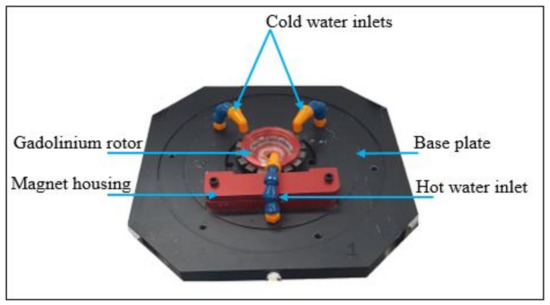
Figure 1.
Operational prototype of the thermomagnetic heat engine.
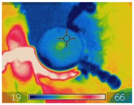
Figure 2.
Temperature zones of thermomagnetic heat engine.
3. Simulation Model of the Thermomagnetic Engine
Figure 3 shows a 3D model of the existing geometry of the TME. The given geometry is exclusively examined for its output performance under different conditions at the COMSOL platform. Table 1 shows the magnetic properties of the materials used in different parts of the thermomagnetic engine. The simulation geometry under study uses the same dimensions as the working model. The simulation steps to evaluate the output performance of the TME are as follows:
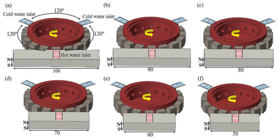
Figure 3.
Simulated models of a thermomagnetic heat engine, consisting of different sizes of magnets and two cold- and a hot-water inlet located at an angle of 120°: (a) thermomagnetic engine consists of 100 mm magnet, (b) thermomagnetic engine consists of 90 mm magnet, (c) thermomagnetic engine consists of 80 mm magnet, (d) thermomagnetic engine consists of 70 mm magnet, (e) thermomagnetic engine consists of 60 mm magnet, and (f) thermomagnetic engine consists of 50 mm magnet.

Table 1.
Magnetic properties of different materials used in the thermomagnetic heat engine.
- In the first step of the simulation, the performance of the existing model of the TME was evaluated based on the axial torque generation in the presence of the magnetic field. The permanent magnet used in the existing model of the thermomagnetic engine has a length and diameter of 100 and 2 mm, respectively. Then, the magnet length was decreased gradually, while the diameter was kept constant at 25 mm. The magnets were placed at a 1 mm distance from the rotor. The zero magnetic scalar potential passes in the middle of the gadolinium blocks. Figure 3 shows bar magnets of different lengths, which were used to compare the output performance, especially the axial torque generation. Moreover, a permanent magnet with different poles (north and south) direction was also investigated for the axial toque generation, as shown in Figure 4.
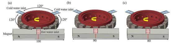 Figure 4. Simulated models of a thermomagnetic heat engine, consisting of different sizes of magnets and two cold- and a hot-water inlet located at an angle of 120°: (a) thermomagnetic engine consists of 100 mm magnet, (b) thermomagnetic engine consists of 90 mm magnet, (c) thermomagnetic engine consists of 80 mm magnet.
 - In the second stage of simulation, the best performing magnet configuration was used for further simulation. As mentioned, the output of the thermomagnetic engine can be improved by increasing the interaction of magnetic flux with gadolinium. Therefore, the geometry of the engine was reformed to introduce one more permanent magnet and hot-water inlet. Figure 5 shows three different geometries of the thermomagnetic engine where the second magnet and hot-water inlet were placed in three different positions (angles). Here, it can be seen that the number of permanent magnets and hot-water inlets was doubled, but not that of the cold-water inlets.
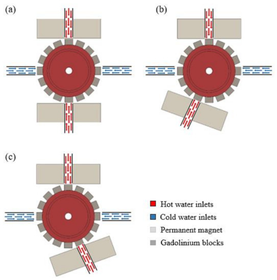 Figure 5. Simulated models of a thermomagnetic heat engine, where cold-water inlets are placed in the same position while the angle between the permanent magnet and hot-water inlets is varied: (a) an angle of 180° between the permanent magnet and hot water inlets, (b) an angle of 160° between the permanent magnet and hot water inlets, and (c) an angle of 200° between the permanent magnet and hot water inlets.
3.1. Governing Equation and Boundary Conditions
COMSOL multiphysics supposes that the thermomagnetic engine is confined by air. In that case, the magnetic force on the gadolinium blocks can be calculated as follows [29]:
F = ∮ · ΩnΓdS
The net force on the gadolinium blocks relies on the performing magnetic force, which is determined by taking the integral of the stress tensor over the entire boundaries of the blocks, as described in Equation (1):
where Γ stands for Maxwell stress tensor, n is the boundary normal pointing out from the block surface, and S is the displacement of the gadolinium blocks. The torque generation by the thermomagnetic engine can be calculated as the cross-product between the magnetic force and the radius of the rotor:
where, is the torque along a specific axis. The exterior boundaries of the air domain are supposed to be a perfect magnetic conductor, where the tangential magnetic field vanishes to zero. This is given as:
where, H represents the magnetic field, and n is the normal vector to the boundary.
τ = ∮·Ω (r − r0) × (nΓ) dS
n × H = 0
3.2. Material Properties and Meshing Strategy
Figure 6 shows the simulation geometry of the thermomagnetic heat engine under study. To minimize the computational time, the air was assumed as the surrounding domain, and the following three major components of the geometry were considered for simulation: permanent magnet, gadolinium blocks, and aluminum rotor. The remanent flux density (Br) and relative permeability (µr) of the permanent magnet were considered to be 1.2 and 1.05, respectively. The relative permeability (µr) of the gadolinium blocks depends on the exposed temperature. Gadolinium blocks exhibit a relative permeability of ~1.6 near room temperature at 20 °C, while it increases to 14 at a temperature of 0 °C. However, the availability of water at 0 °C for commercial implementation is not feasible and so is the operation of TME. Therefore, the simulation analysis was carried out considering the actual scenario, where relative permeability of ~1.6 was assigned to the gadolinium blocks influenced by cold water inlets at room temperature. Similarly, gadolinium blocks exposed to hot water inlets reveal a relative permeability of 1 in the comsol simulation analysis. Figure 7 plots the relationship between the relative permeability and temperature [30]. The relative permeability (µr) of the cylindrical rotor was held to be 1, as it was made from aluminum. Figure 8 shows the simulation model after applying the meshing strategy.
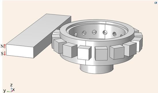
Figure 6.
Simulation model of the thermomagnetic heat engine.
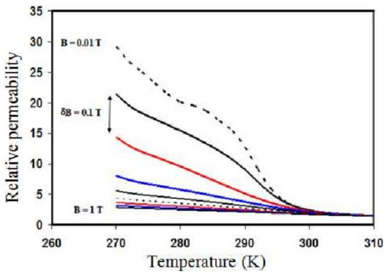
Figure 7.
Relationship between the temperature and relative permeability of gadolinium.
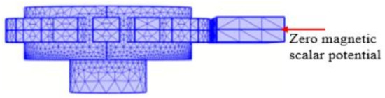
Figure 8.
Mesh analysis of the TME model.
4. Numerical Results
Different sizes of the rectangular magnet were studied to follow up the output performance of the TME for the applied magnetic field. In the first section of the simulation, the length of the permanent magnet was gradually reduced from 100 to 50 mm by keeping its diameter constant at 25 mm, as can be seen in Figure 9. This study reveals how the placement of the magnet’s pole near the rotor affects the torque generation of the TME.
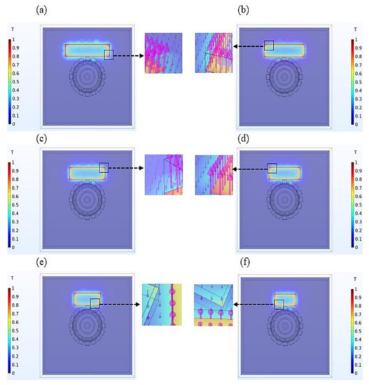
Figure 9.
Simulation results of different models of thermomagnetic engine: (a) magnetic flux distribution of 100 mm rectangular shape magnet, (b) magnetic flux distribution of 90 mm rectangular shape magnet, (c) magnetic flux distribution of the optimized size (80 mm) of the magnet, (d) magnetic flux distribution of 70 mm rectangular shape magnet, (e) magnetic flux distribution of 60 mm rectangular shape magnet, and (f) magnetic flux distribution of 50 mm rectangular shape magnet.
Figure 9a illustrates the simulation analysis of the existing model of the TME, which contains a rectangular magnet having a length and diameter of 100 and 25 mm, respectively. The actual length of the rectangular magnet is considerably larger than the diameter of the rotor, which causes an overall distance of 22 mm between the magnet poles and the edges of the cubic gadolinium blocks. In such a case, the axial torque of the TME is calculated to be 25.9 N.mm, where the magnetic energy exerted by the magnet is 8.7 J. Figure 9b shows another TME model having a 90 mm long permanent magnet. In this case, the distance between the magnet poles and the gadolinium blocks is 12 mm, which is comparatively closer to the rotor than the previous existing model of the TME. The total magnetic energy of the magnet is 7.8 J, and the axial torque caused by the TME is 26.3 N.mm. Figure 9c represents another geometry of the TME which incorporates an 80 mm long rectangular shape magnet. In this particular case, the length of the permanent magnet is almost equal to the gadolinium rotor from one end to the other. In other words, there is no considerable distance between the magnet poles, and the edges of the gadolinium blocks. This assembly of the TME leads to an axial torque and magnetic energy of 27 N.mm and 7 J, respectively. Figure 9d presents the simulation results of another scenario, where the effectiveness of a 70 mm magnet is studied for the torque generation. Figure 9d shows that the total length of the magnet is smaller than that of the gadolinium rotor. At this point, the axial torque is 24.6 N.mm, whereas the total magnetic energy is 6.12 J. As illustrated in Figure 9e, the total length of the permanent magnet is further decreased to be less than the edges of the gadolinium rotor. In this case, the TME exhibits an axial torque of 23.3 N.mm, where the permanent magnet length is 60 mm. Additionally, the total magnetic energy is measured to be 5.1 J. Figure 9f shows the case in which a smaller magnet of 50 mm is employed in the simulation model. The magnetic energy exerted by the magnet is 4.2 J; it produces an axial torque of 22.6 N.mm, which is the minimum among all the six TME models, because the magnet length is much smaller than that of the gadolinium rotor.
It can be concluded from the above analysis that the generation of the axial torque dominantly relies on the size of the permanent magnet. In this study, the permanent magnet in Figure 9c with a length of 80 mm and a diameter of 25 mm outperformed the others in terms of axial torque generation. Figure 10a illustrates the relationship of the length of the magnet and the produced axial torque by the TME, while Figure 10b shows the total magnet energy employed by the magnet on the TME.
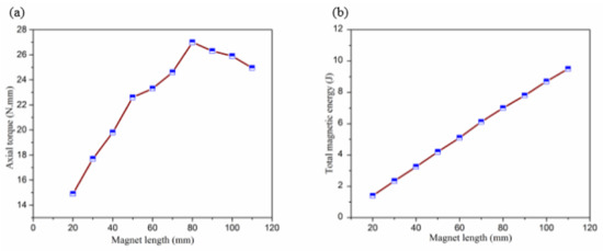
Figure 10.
(a) Magnetic length vs. axial torque generation, and (b) magnetic length vs. total magnetic energy.
Further, different sizes of permanent magnets with different polar directions were investigated for the axial torque generation to validate the results. Figure 11 shows the simulation results for the TME models considered. The TME model shown in Figure 11a has a magnet with a length and diameter of 100 and 25 mm, respectively. In this case, the torque generated by the TME is 1.6 N.mm. The TME model in Figure 11b produces an axial torque of 2.3 N.mm, where the length of the used magnet is 90 mm. Another model of the TME shown in Figure 11c uses a permanent magnet with a length of 80 mm. In this case, the measured axial torque was 4.2 N.mm. The analysis clearly describes that the torque generation by these TME models is not even comparable with the above TME models shown in Figure 9. Therefore, the optimal magnet shown in Figure 9c was considered for further simulation analysis.
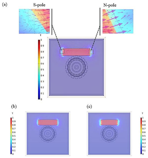
Figure 11.
Simulation results of different models of thermomagnetic engine: (a) magnetic flux distribution of 100 mm magnet, (b) magnetic flux distribution of 90 mm magnet, (c) magnetic flux distribution of 80 mm magnet.
As stated earlier, the output performance of the TME can be improved by increasing the number of hot-water inlets, as well as permanent magnets. Therefore, in the second stage of the simulation, the geometry of the TME is modified to incorporate more permanent magnets and hot-water inlets at three different positions, as shown in Figure 12. Based on the above simulation analysis, we used the outperformed 80 mm magnet in the modified geometry of the TME. Figure 12a shows simulation results for the modified model of the TME where the two magnets and hot-water inlets were placed with 180° angles between them. In this case, the net measured torque was 40 N.mm. In Figure 12b, the angle between the permanent magnets and the hot-water inlets was maintained at 160°, which generated an axial torque of 34.2 N.mm. Figure 12c shows the final investigated model of the TME. In this model, the two magnets and hot-water inlets were kept at an angle of 200° to each other. In this context, the measured axial torque generation is 32.9 N.mm. The above simulation results identify that the angle between water inlets (hot and cold) also plays a vital role in axial torque generation. According to the simulation results, the TME model in Figure 12a outperformed the other models in terms of axial torque generation. Figure 13 shows a relationship between the axial torque and the position of the hot-water inlets and permanent magnet.
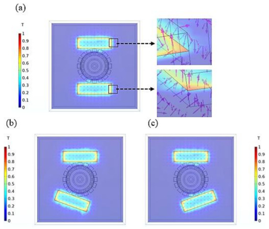
Figure 12.
Simulation results of different models of a thermomagnetic heat engine, where two permanent magnets are placed at different positions to each other: (a) 180°, (b) 160°, and (c) 200°.
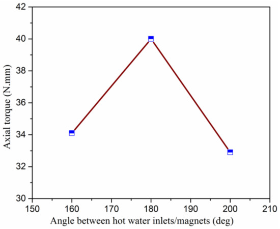
Figure 13.
Relationship between torque generation and the position (angle) between hot-water inlets and the permanent magnet.
5. Laboratory Experimentation of the Optimized TME
Based on the above simulation analysis, the geometry of the TME was modified by optimizing the size of the permanent magnet. Additionally, the number of optimal permanent magnets, as well as the number of heat sources, was increased in the newly designed geometry. As a result, the unbalanced magnetic forces were generated twice in one cycle of the TME operation. Figure 14 shows the prototype of the optimal TME model that was fabricated for practical applications. The fabricated thermomagnetic engine was operated with different temperatures of hot-water jets to experimentally determine torque generation and rotational speed. The temperature of the hot-water inlet was gradually increased from 31 to 96 °C with a 5 °C increment, whereas that of the cold-water inlet was kept constant at 21 °C. The given temperature difference causes a cyclic change in the magnetic properties of the gadolinium blocks, and the engine starts to produce rotational motion. Figure 15a illustrates a comparison of rotational speed and difference in temperature between hot- and cold-water inlets. The rotational speed and the torque of the engine were measured by digital tachometer (Model: DM6234P+) and Tohnichi torque gauge (Model: 9BTG), respectively. The test run of the engine was carried out at a constant flow rate of 400 and 800 mL/min for the hot- and cold-water inlets, respectively. It is because of the engine’s output performance, which is directly related to the water flow rate. Increasing the water flow rate after a certain value, the splashes from the water inlets (hot or cold) start affecting the surrounding gadolinium blocks. As a result, it will start to diminish the difference in temperature from the affected zones and hence the output performance will be seriously affected. Therefore, the flow rate chosen in the experiment is the maximum while maintaining the spilling and splashing to a minimum. The water flow was provided and controlled by using Lab Companion (RW-3025G) during the experiments.
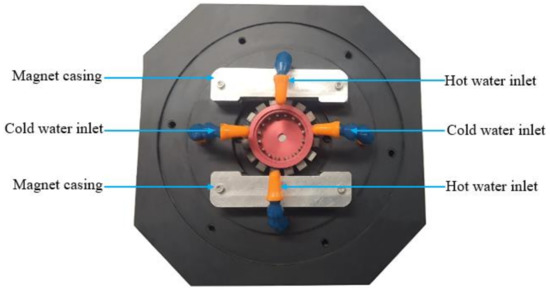
Figure 14.
Operational prototype of the optimized model of thermomagnetic engine.
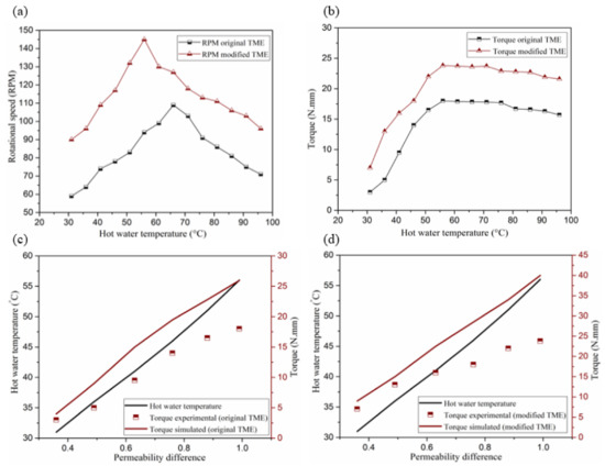
Figure 15.
(a) Comparison of the rotational speed values between the original and modified configuration of the thermomagnetic engine. (b) Comparison of torque values between the original and modified configuration of the thermomagnetic engine. (c) Comparison of the experimental and simulated values of torque for the original configuration of the heat engine. (d) Comparison of the experimental and simulated values of torque for the modified configuration of the heat engine.
Figure 15a shows that both the original and modified TME models reach their maximum rotational speed at a specific hot-water temperature. However, with a further increase of the hot-water temperature, the rotational speed of both engines is reduced. This is because of the limited heat transfer of the TME after a certain temperature of the hot-water inlets, where the cold-water inlets are unable to cool down or lower the temperature of the gadolinium blocks exposed to the hot-water inlets. Therefore, the magnetic properties of the gadolinium decrease, which results in the reduction of RPM after this critical point. This critical value of hot-water temperature is obtained at 66 °C for the original TME model, and 56 °C for the modified configuration of the thermomagnetic heat engine. It is important to note that the modified geometry experiences the critical point at a lower temperature of 56 °C, compared to the original geometry at 66 °C as can be seen in Figure 15a. One of the main contributing factors is the reduction in the amount of heat transferred through heat sinks, as the original configuration of the TME uses two cold-water inlets (heat sinks) to cool the gadolinium blocks during rotation. Meanwhile, in the modified geometry of the thermomagnetic heat engine, one cold-water inlet is deployed after each hot-water inlet to perform this function. Therefore, compared to the original heat engine, the modified configuration has a higher temperature.
Figure 15c,d compares the experimental torque values with the simulated ones for the original and modified configurations of the thermomagnetic engine, respectively. In both cases, the simulated torque has higher values, and it increases at a different rate compared to the experimental torque. This is related to the fact that the simulation model addresses the entire geometry of the gadolinium blocks, while calculating the amount of generated torque. In other words, any block that makes contact with the water attains the inlet temperature, which would be an ideal scenario. In the actual scenario, only some portion of the gadolinium geometry experiences temperature change during the experiment.
From the presented results it can be inferred that compared to the original configuration of the thermomagnetic heat engine, the modified TME model shows better performance. This means that increasing the number of heat sources and permanent magnets can significantly improve the overall output performance of the proposed system. Additionally, note that introducing more heat sinks and permanent magnets to the geometry can further improve the output performance of the thermomagnetic heat engine. However, the geometry should be configured in such a way that the permanent magnets maintain sufficient distance between one another, and do not magnetically interact with each other.
The mechanical power of the system is calculated by using Equation (6).
where T is the torque in N.mm and N is the rotational speed of the system in rpm.
Similarly, the thermal energy input of the system is calculated by using Equation (7) as follows:
where qin is the total input energy given to the system in J; m and c are the mass and specific heat capacity of the water in g and J/g °C, respectively, and ΔT represents the temperature difference in °C between hot- and cold-water inlets.
Optimal operating conditions are considered to calculate the thermal efficiency of the system by using Equation (8):
where wm and qin are the mechanical power output and total energy input of the thermomagnetic engine, respectively. The thermal conversion efficiency and mechanical power of the proposed system are calculated to be 0.144% and 363 mW at ΔT = ~46 °C, respectively. Though, the thermal conversion efficiency seems to be lower than other types of heat engines. It, however, displayed higher thermal conversion efficiency in comparison with other types of thermomagnetic heat engines [26,27].
6. Conclusions
In this study, different simulation models of our previously designed thermomagnetic heat engines were developed to analyze different aspects for an optimized model of a thermomagnetic heat engine. In particular, the numerical analysis was performed to study the output performance of the proposed thermomagnetic engine in the presence of an applied magnetic field.
As a first step, permanent magnets of different types and different lengths were investigated for higher axial torque generation. The 80 mm long permanent magnet was found to generate higher torque than the 100 mm permanent magnet used in our previously designed thermomagnetic generator. The outperforming/optimal magnet was used for further simulation. Secondly, we introduced one more permanent magnet and hot-water inlet to the geometry. Additionally, the best positions (angles) for the extra permanent magnet and hot-water inlet were investigated. Lastly, based on the simulation results, an optimized model of the TME was designed for practical applications.
According to the simulation results, the optimal size of the magnet improved the output performance of the TME. Additionally, the addition of an extra permanent magnet and hot-water inlet produced significant improvements in the output results. The laboratory trials reveal that the peak torque of the TME increased from 18 ± 1 to 23.8 ± 1% N.mm, which is an increase of 32.2%. In addition, the modified engine boosts the rotational speed (RPM) from 109 ± 1.5 to 146 ± 1.5%, an increase of 34.3%. Meanwhile, the limitations owing to heat conduction were again examined in this configuration. The modified engine attains its maximum output at a lower temperature of hot water, compared to the original engine. The heat transfer efficiency can be enhanced with a higher circumference of gadolinium rotor having more magnets and heat sinks. Nevertheless, there is much room to further improve the performance of thermomagnetic heat engines for the practical application of harnessing low grade thermal energy.
Author Contributions
Conceptualization, Z. and S.C.; methodology, Z.; software, S.C.; validation, Z., M.U.M. and S.C.; formal analysis, M.U.M.; investigation, S.C.; resources, S.C.; data curation, M.U.M.; writing—original draft preparation, Z.; writing—review and editing, Z.; visualization, Z.; supervision, S.C.; project administration, S.C.; funding acquisition, S.C. All authors have read and agreed to the published version of the manuscript.
Funding
This research was supported by National Research Foundation of Korea (NRF-2019R1A2C1088680 and 2018M3A9F1023691) and by the GRRC program of Gyeonggi province (GRRC-Gachon2020(B01), AI-based Medical Image Analysis).
Institutional Review Board Statement
Not applicable.
Informed Consent Statement
Not applicable.
Data Availability Statement
The study did not report any data.
Conflicts of Interest
The authors declare no conflict of interest.
References
- Forman, C.; Muritala, I.K.; Pardemann, R.; Meyer, B. Estimating the global waste heat potential. Renew. Sustain. Energy Rev. 2016, 57, 1568–1579. [Google Scholar] [CrossRef]
- Olsen, R.B. Ferroelectric Conversion of Heat to Electrical EnergyA Demonstration. J. Energy 1982, 6, 91–95. [Google Scholar] [CrossRef]
- Olsen, R.B.; Briscoe, J.M.; Bruno, D.A.; Butler, W.F. A pyroelectric energy converter which employs regeneration. Ferroelectrics 1981, 38, 975–978. [Google Scholar] [CrossRef]
- Olsen, R.; Brown, D. High efficiency direct conversion of heat to electrical energy-related pyroelectric measurements. Ferrolectrics 1982, 40, 17–27. [Google Scholar] [CrossRef]
- Hsu, C.-T.; Huang, G.-Y.; Chu, H.-S.; Yu, B.; Yao, D.-J. An effective Seebeck coefficient obtained by experimental results of a thermoelectric generator module. Appl. Energy 2011, 88, 5173–5179. [Google Scholar] [CrossRef]
- Fedelich, B.; Zanzotto, G. One-dimensional quasistatic nonisothermal evolution of shape-memory material inside the hysteresis loop. Contin. Mech. Thermodyn. 1991, 3, 251–276. [Google Scholar] [CrossRef]
- Raniecki, B.; Lexcellent, C.; Tanaka, K. Thermodynamic models of pseudoelastic behaviour of shape memory alloys. Arch. Mech. 1992, 44, 261–284. [Google Scholar]
- Kirol, L.D.; Mills, J.I. Numerical analysis of thermomagnetic generators. J. Appl. Phys. 1984, 56, 824–828. [Google Scholar] [CrossRef]
- Stauss, H.E. Efficiency of Thermomagnetic Generator. J. Appl. Phys. 1959, 30, 1622–1623. [Google Scholar] [CrossRef]
- Maas, G.V.D.; Purvis, W.J. “Curie point” motor. Am. J. Phys. 1956, 24, 176–177. [Google Scholar] [CrossRef]
- Trapanese, M. A dq axis theory of the magnetic, thermal, and mechanical properties of Curie motor. J. Appl. Phys. 2011, 109. [Google Scholar] [CrossRef]
- Franzitta, V.; Viola, A.; Trapanese, M. Design and Test of a Thermomagnetic Motor Using a Gadolinium Rotor. Appl. Mech. Mater. 2013, 432, 324–329. [Google Scholar] [CrossRef]
- Trapanese, M.; Cipriani, G.; Di Dio, V.; Franzitta, V.; Viola, A. Optimization of a thermomagnetic motor. J. Appl. Phys. 2015, 117, 17A750. [Google Scholar] [CrossRef]
- Takahashi, Y.; Irie, T.; Nishikawa, M. Experiment on Cylindrical Thermomagnetic Engine for Exhaust Heat Recovery. IEEJ Trans. Power Energy 2003, 123, 389–394. [Google Scholar] [CrossRef]
- Takahashi, Y.; Matsuzawa, T.; Nishikawa, M. Fundamental performance of the disc-type thermomagnetic engine. Electr. Eng. Jpn. 2004, 148, 26–33. [Google Scholar] [CrossRef]
- Takahashi, Y.; Yamamoto, K.; Nishikawa, M. Fundamental performance of triple magnetic circuit type cylindrical thermo-magnetic engine. Electric. Eng. Jpn. 2006, 154, 68–74. [Google Scholar] [CrossRef]
- Chun, J.; Song, H.-C.; Kang, M.-G.; Kang, H.B.; Kishore, R.A.; Priya, S. Thermo-Magneto-Electric Generator Arrays for Active Heat Recovery System. Sci. Rep. 2017, 7, 41383. [Google Scholar] [CrossRef]
- Ujihara, M.; Carman, G.P.; Gil Lee, D. Thermal energy harvesting device using ferromagnetic materials. Appl. Phys. Lett. 2007, 91, 093508. [Google Scholar] [CrossRef]
- Song, H.C.; Maurya, D.; Chun, J.; Zhou, Y.; Song, M.E.; Gray, D.; Yamoah, N.K.; Kumar, D.; McDannald, A.; Jain, M.; et al. Modulated magneto-thermal response of La0.85Sr0.15MnO3 and (Ni0.6Cu0.2Zn0.2) Fe2O4 composites for thermal energy harvesters. Energy Harvest. Syst. 2017, 4, 57–65. [Google Scholar] [CrossRef]
- Bulgrin, K.E.; Ju, Y.S.; Carman, G.P.; Lavine, A.S. A coupled thermal and mechanical model of a thermal energy harvesting device. In Proceedings of the ASME 2009 International Mechanical Engineering Congress and Exposition, Lake Buena Vista, FL, USA, 13–19 November 2009; pp. 327–335. [Google Scholar]
- Joshi, K.B.; Priya, S. Multi-physics model of a thermo-magnetic energy harvester. Smart Mater. Struct. 2013, 22. [Google Scholar] [CrossRef]
- Murakami, K.; Nemoto, M. Some experiments and considerations on the behavior of thermomagnetic motors. IEEE Trans. Magn. 1972, 8, 387–389. [Google Scholar] [CrossRef]
- Andreevskii, K.N.; Mandzhavidze, A.G.; Margvelashvili, I.G.; Sobolevskaya, S.V. Investigation of the thermodynamic and physical char-acteristics of a thermomagnetic engine with a gadolinium working element. Tech. Phys. 1998, 43, 1115–1118. [Google Scholar] [CrossRef]
- Chen, C.-C.; Chung, T.-K.; Tseng, C.-Y.; Yeh, P.-C.; Cheng, C.-C. A miniature magnetic-piezoelectric thermal energy harvester. IEEE Trans. Magn. 2015, 51, 1–9. [Google Scholar] [CrossRef]
- Chun, J.; Kishore, R.A.; Kumar, P.; Kang, M.G.; Kang, H.B.; Sanghadasa, M.; Priya, S. Self-powered temperature mapping sensors based on thermo-magneto-electric generator. ACS Appl. Mater. Interfaces 2018, 10, 10796. [Google Scholar] [CrossRef] [PubMed]
- Zeeshan; Ahmed, R.; Chun, W.; Oh, S.J.; Kim, Y. Power Generation from a Hybrid Generator (TENG-EMG) Run by a Thermomagnetic Engine Harnessing Low Temperature Waste Heat. Energies 2019, 12, 1774. [Google Scholar] [CrossRef]
- Ahmed, R.; Kim, Y.; Mehmood, M.U.; Zeeshan; Shaislamov, U.; Chun, W. Power generation by a thermomagnetic engine by hybrid operation of an electromagnetic generator and a triboelectric nanogenerator. Int. J. Energy Res. 2019, 43, 5852–5863. [Google Scholar] [CrossRef]
- Zeeshan; Ahmed, R.; Mehmood, M.U.; Kim, Y.; Lee, J.; Chun, W. Harnessing low-grade waste heat by operating a hybrid piezoelectric-electromagnetic energy harvester combined with a thermomagnetic engine. Int. J. Energy Res. 2020, 44, 10710–10723. [Google Scholar] [CrossRef]
- Comsol Inc. Comsol Multiphysics Users Guide; Comsol Inc.: Stockholm, Sweden, 2012. [Google Scholar]
- Bouchekara, H.R.E.-H.; Kedous-Lebouc, A.; Yonnet, J.P. Electromagnetic design of a magnetic field source for a magnetocaloric refrigerator. Prog. Electromagn. Res. 2011, 19, 251–263. [Google Scholar] [CrossRef][Green Version]
Publisher’s Note: MDPI stays neutral with regard to jurisdictional claims in published maps and institutional affiliations. |
© 2021 by the authors. Licensee MDPI, Basel, Switzerland. This article is an open access article distributed under the terms and conditions of the Creative Commons Attribution (CC BY) license (https://creativecommons.org/licenses/by/4.0/).