1. Introduction
The expected increase of Distributed Energy Resources (DER) in distribution grids, such as Renewable Energy Sources (RES), Electric Vehicles (EV) and distributed Energy Storage Systems (ESS), is highlighting new challenges regarding operation and control of electric power systems [
1,
2,
3,
4,
5]. In order to face this new paradigm, advanced concepts aimed to improve controllability and observability of distribution grids have been proposed, such as the microgrid, being regarded as the building block of the broader smart-grids concept [
6,
7,
8,
9,
10,
11].
AC microgrids have constituted the initial approaches to tackle those challenges [
7,
8,
12], but advancements in power electronics have motivated an increasing interest in DC distribution microgrids, presenting advantages for the integration of resources which are DC by nature such as PV generation, ESS and EV charging [
13,
14]. The possibility of employing both AC and DC grids for DER integration has attracted attention for the Smart-Transformer (ST) concept as a possible technical solution to improve the controllability of future distribution grids [
15,
16,
17]. The ST is a three-stage Solid-State Transformer (SST) adapted for advanced monitoring and control of distribution grids [
16,
17].
However, comparatively to traditional low-frequency magnetic transformers, the ST inherently presents stringent challenges regarding particular operation conditions involving overcurrents—namely overloads and short-circuits—since it is based on power electronic converters. Fault-Ride-Through (FRT) capabilities in ST are of upmost importance not only for the physical integrity of the ST itself but also for the continuity of supply of the hybrid AC/DC distribution grid derived from the ST itself. The development of FRT capabilities for electronic power converters, especially for distributed generation, has been extensively addressed in the literature [
18,
19,
20,
21,
22]. The incorporation of FRT capabilities in Medium-Voltage (MV) inverters is also an important research topic [
22,
23,
24,
25]. Nevertheless, the inclusion of FRT capabilities in ST remains scarcely addressed in the literature, there being a single work on the subject to date, to the best of the authors’ knowledge [
26].
In [
26], FRT strategies are proposed for grid-forming ST and for grid-tied ST without local energy storage integrated in the ST’ DC stage. Regarding grid-tied ST, the FRT strategy proposed in [
26] aims to mitigate the adverse impacts in the hybrid AC/DC grid derived from the ST, by exploiting the active power-voltage sensitivity of LV DC and LV AC sub-networks in order to support net load and net generation balancing in the hybrid AC/DC distribution grid during voltage sags in the upstream MV AC grid. The ST’s MV inverter will increase its injected/absorbed current in order to preserve the power balance in the hybrid AC/DC distribution grid. However, when ST’s MV inverter reaches its current limits, the FRT strategy is activated in order to preserve the power balance, by reducing/increasing the load/generation in the ST’s hybrid AC/DC distribution grid when it is importing active power, or by increasing/reducing the load/generation in the ST’s hybrid AC/DC distribution grid when it is exporting active power.
Simultaneously, the FRT strategy proposed in [
26] aims to minimize its impact on the voltage levels in the hybrid AC/DC grid (when current levels in the MV AC inverter saturate during a voltage sag in the MV AC grid) to the strictly necessary to ensure the aimed power balancing in the hybrid AC/DC grid. Thus, besides ensuring power balance in the hybrid AC/DC grid, the FRT strategy proposed in [
26] simultaneously improves the voltage levels in the hybrid AC/DC network, circumventing as much as possible the absence of local energy storage capacity associated to the grid-tied ST. However, the methodology proposed in [
26] has the following limitations:
It cannot exploit the active power-voltage sensitivity of an MV DC sub-network constituting the hybrid AC/DC distribution grid. The proposed FRT strategy may be less effective if most of the load/generation is located in a MV DC sub-network.
It cannot exploit power-frequency sensitive DER located in the LV AC sub-network constituting the hybrid AC/DC distribution grid [
27]. This feature would enable the regulation of the net active power in the LV AC sub-network with minimal impact on non-controllable resources.
It is not capable of exploiting complementary solutions (dump loads, controllable PV generation or ESS available in the hybrid AC/DC grid to further support the power balancing phenomena and voltage control mechanisms in the hybrid distribution grid in the moments subsequent to the fault.
It is evaluated only for balanced three-phase voltage sags in the upstream MV AC grid.
This paper proposes an improved FRT control strategy for grid-tied ST with no local energy storage capacity suitable to bridge the aforementioned limitations. Following a MV AC grid voltage sag, to foster net load balance downstream from the ST, the proposed FRT control strategy relies on the exploitation of active power-frequency sensitivity in the LV AC sub-network, on the exploitation of active power-voltage sensitivity in LV DC and AC sub-networks by adjusting the transformation ratio of the ST’s isolated DC-DC converter, and on the exploitation of active power-voltage sensitivity in MV DC sub-network by adjusting an electronic resistor added in series with the MV DC sub-network specifically for this purpose. The main purpose of the electronic resistor proposed to be integrated in the MV DC sub-network is to provide an additional degree of freedom regarding voltage control in the hybrid AC/DC grid during grid faults in the ST’s upstream AC grid. In order to support net generation balance downstream from the ST following an AC MV grid fault, the proposed FRT control strategy relies on a dump-load incorporated in the ST specifically for this purpose. Under the proposed FRT strategy, controllable PV generation and ESS available in the ST’s hybrid AC/DC distribution grid and sensitive to grid voltage and/or frequency can also be exploited to minimize the excess net load/generation in the ST’s hybrid AC/DC distribution grid.
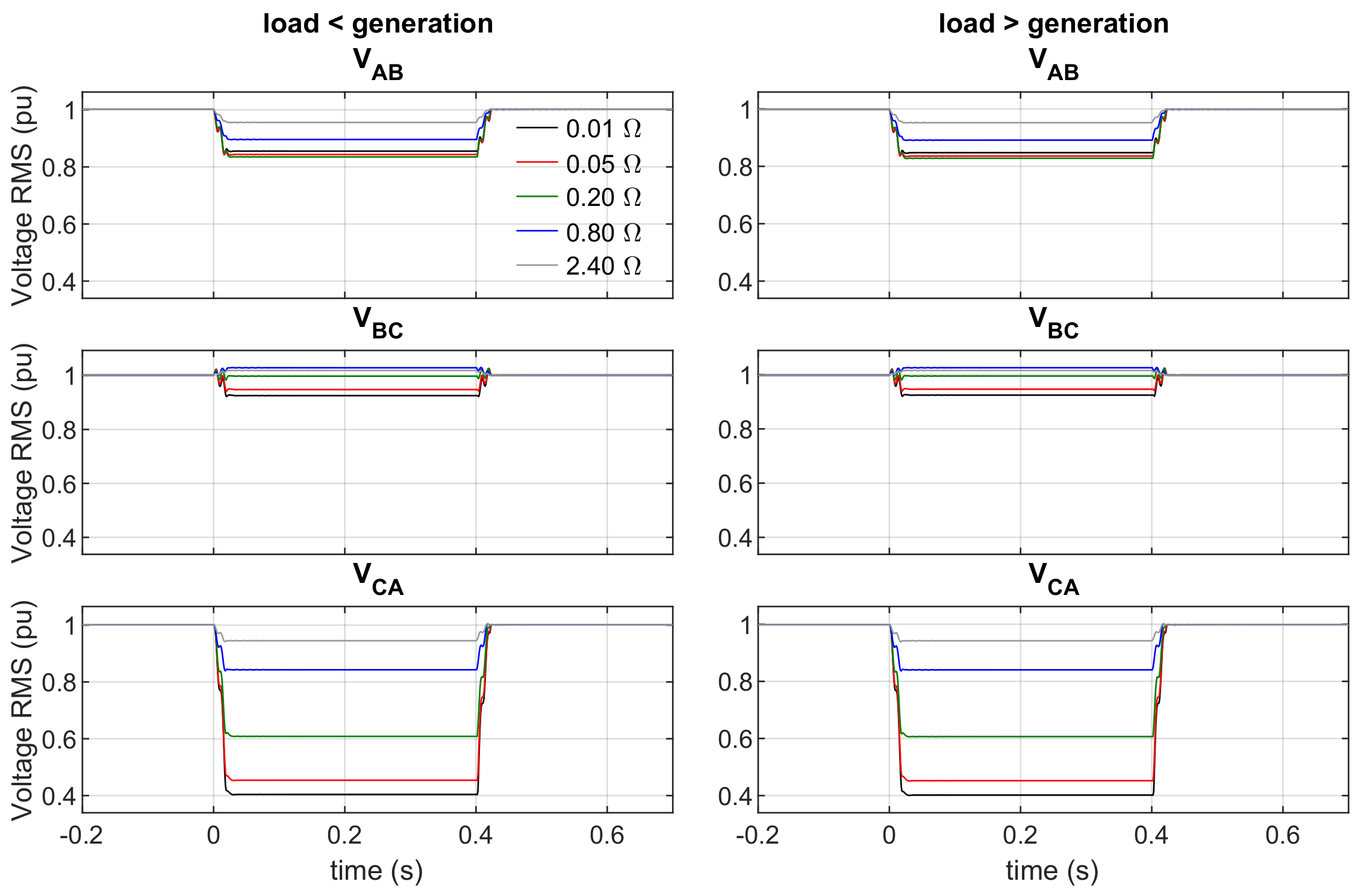
The FRT approach proposed in this paper is evaluated for voltage sags resulting from balanced three-phase faults and unbalanced phase–phase and phase-ground faults in the upstream AC grid. An electronically controlled supercapacitor bank is connected to the ST’s LV DC bus, aiming to mitigate power oscillations in the ST’s DC buses that may result from the unbalanced voltage sags in the upstream AC grid. The effectiveness of the proposed FRT strategy, in enabling the ST to ride through voltage sags in the upstream AC grid while mitigating adverse impacts affecting the ST’s hybrid distribution grid, is demonstrated in this paper through computational simulation.
2. Computational Models
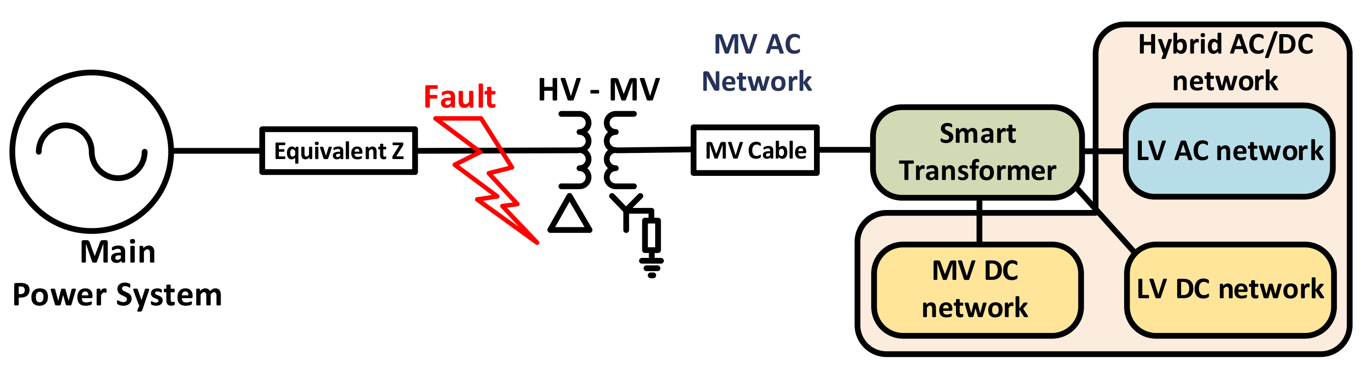
The effectiveness of the approaches suggested in this paper is studied and demonstrated using a test network modeled in a computational simulation environment. An over-view of the test network is depicted in
Figure 1, comprising a hybrid AC/DC distribution grid connected to an upstream MV AC grid through a grid-tied ST. A MV cable models the equivalent impedance in the MV AC grid between the ST and the HV AC grid. The MV AC grid is connected to a High-Voltage (HV) grid, modeled using a Thevenin equivalent comprising an ideal three-phase voltage source in series with an equivalent impedance. This simplification is adopted because frequency variations that may result from grid faults in the power system are not relevant for the subjects under study in this paper. A DYn core type HV/MV transformer was considered to interface HV and MV AC grids, where a neutral earthing through an impedance was considered for the MV AC grid.
The models for the ST are presented and described in
Section 2.1. The models for the ST’s hybrid AC/DC distribution grid are presented and described in
Section 2.2 (LV AC network) and
Section 2.3 (MV and LV DC networks). The modeling of the controllable DER incorporated in the hybrid distribution network is described in
Section 2.4.
The simulation models were developed in MATLAB
®/Simulink
® environment. A switching frequency of 20 kHz is chosen for the ST’s power converters since it is a realistic value for high power converters [
16,
28,
29]. However, given the considerable computational burden implicit to a detailed computational model simulating power converters operating at such frequency, the Dynamic Average Modeling (DAM) technique proposed in [
30] was adopted. The DAM technique uses the moving average operator at the switching frequency to eliminate the need of modeling detailed switching elements [
30]. Thus, the detailed power converters can be represented by controllable voltage and current sources without compromising their main dynamic behavior, and the respective control signals can be discretized at the switching frequency by choosing a simulation time step of 50
s. As a result, the switching effects from the computational model are neglected while obtaining a better compromise between computational burden and model accuracy.
2.1. Smart Transformer
This section aims to summarize the main modeling approach for the ST components. The proposed control options and mitigation solutions regarding the specific case of FRT following MV AC grid voltage sags are described in
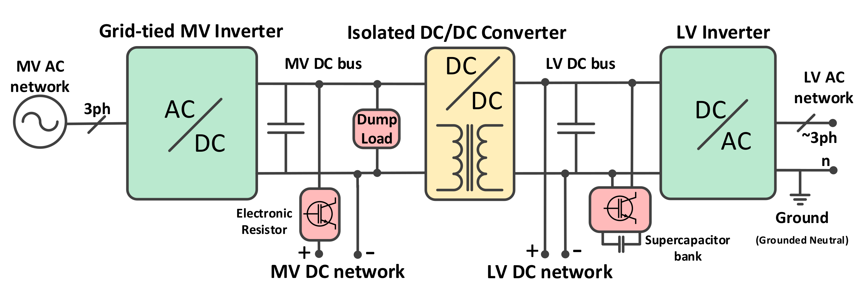
Section 3. The main modules considered in the modeled three-stage ST are depicted in
Figure 2 and described in the following subsections.
2.1.1. Medium Voltage Inverter
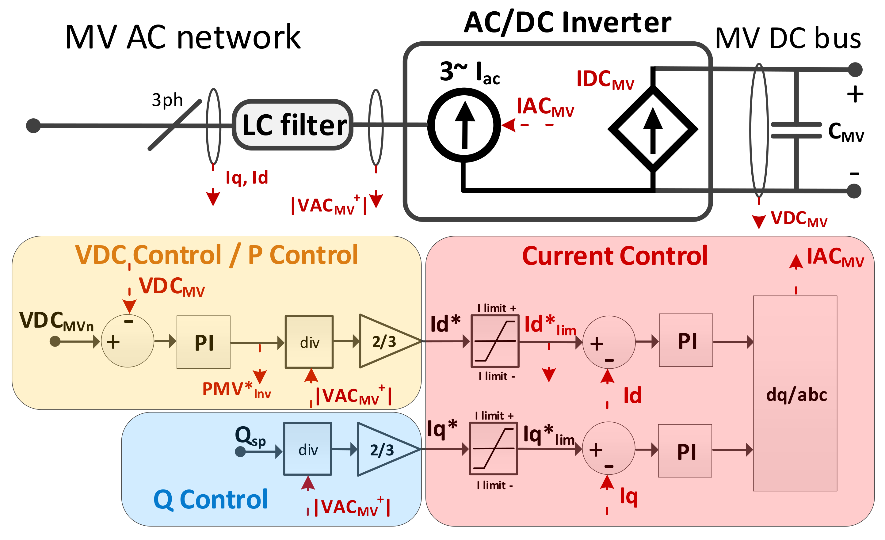
The model of ST’s MV inverter is illustrated in
Figure 3. The power stage of the MV inverter (AC/DC Inverter) and the coupling LC filter are modeled following the assumptions adopted in [
27] for the grid-tied ST, where the DAM technique is also adopted. No neutral connection was considered for the MV inverter.
The active power flow in the MV inverter is modeled according to Equation (
1), which determines the power transfer between the coupling LC filter and the MV DC bus.
is the DC current injected in the MV DC bus,
and
are the active power and the DC voltage in the connection with the MV DC bus,
,
and
are the phase–phase MV AC voltages (between phases
a,
b and
c) in the MV inverter, and
,
and
are the AC currents in the MV inverter’s phases
a,
b and
c (
).
is determined according to Equation (
2), where
is the capacitance of the MV DC bus, and
,
and
are the currents exchanged between the MV DC bus and the isolated DC/DC converter, the MV DC grid and the dump-load, respectively.
Regarding the control structure of the MV inverter, VDC Control / P Control regulates
by generating the reference for the active current (
) to be followed by the Current Control, which then establishes the active current in the MV inverter. The reference for the reactive current generated by Q Control is set to zero (
) given that voltage/VAr support is not addressed in this paper. Only the the positive-sequence component of the current is considered for the controller of the MV inverter. As it will be later discussed in
Section 3, the control of the negative-sequence component of the current by the MV inverter, in comparison to the use of a supercapacitor bank, does not represent the most advantageous approach to mitigate power oscillations that may arise in the ST’s DC buses as a result of unbalanced voltage sags in the MV AC grid. The zero sequence component of the current does not occur since no neutral connection exists in the MV inverter.
2.1.2. Isolated DC/DC Converter
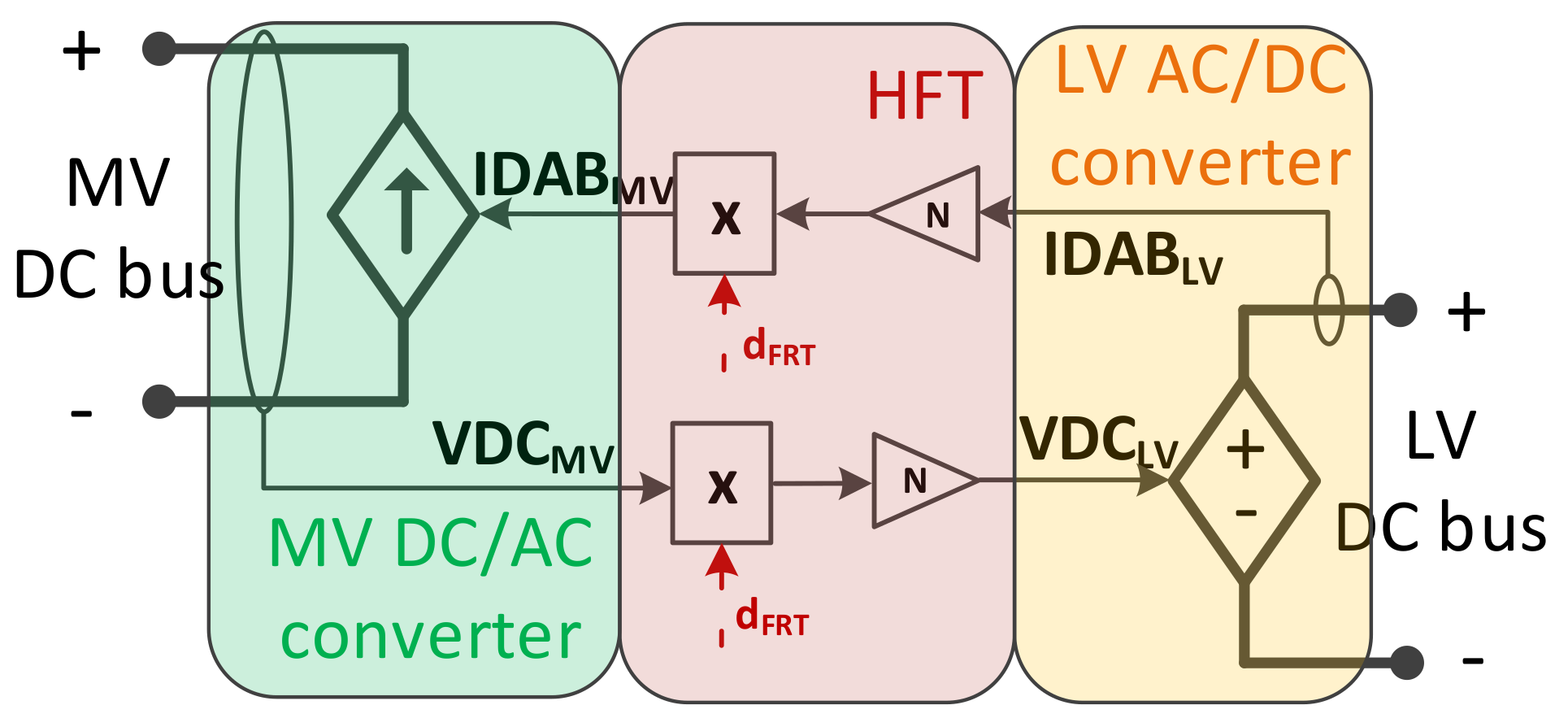
The isolated DC/DC converter was modeled according to the approach presented in [
31], following the considerations described in [
26]. The resulting model is depicted in
Figure 4 and expressed in Equations (
3) and (
4), where
and
are the voltages in the HFT,
and
are the nominal voltages for the ST’s MV and LV DC buses respectively,
and
are the currents in the HFT’s primary and secondary stages respectively, and
is the duty-cycle adjustment signal.
2.1.3. Electronic Resistor
The contribution of the MV DC grid for the provision of FRT is important since it may concentrate a large share of the total load of the hybrid distribution network. While it is possible to modulate the voltage levels in the ST’s LV DC bus in order to directly exploit the power-voltage sensitivity in the LV DC grid [
26], the same approach is not suitable for the ST’s MV DC bus in practical terms. Since the MV AC voltage in the ST’s MV inverter is imposed by the upstream MV AC grid, allowing the FRT control to reduce the MV DC bus voltage can in practice originate passive rectification in the ST’s MV inverter. Passive rectification is an uncontrolled operation mode of the ST MV inverter which can occur when the voltage in the MV DC bus is not enough to block the intrinsic diodes existing in the electronic switches, originating uncontrolled currents capable to damage the ST’s MV inverter.
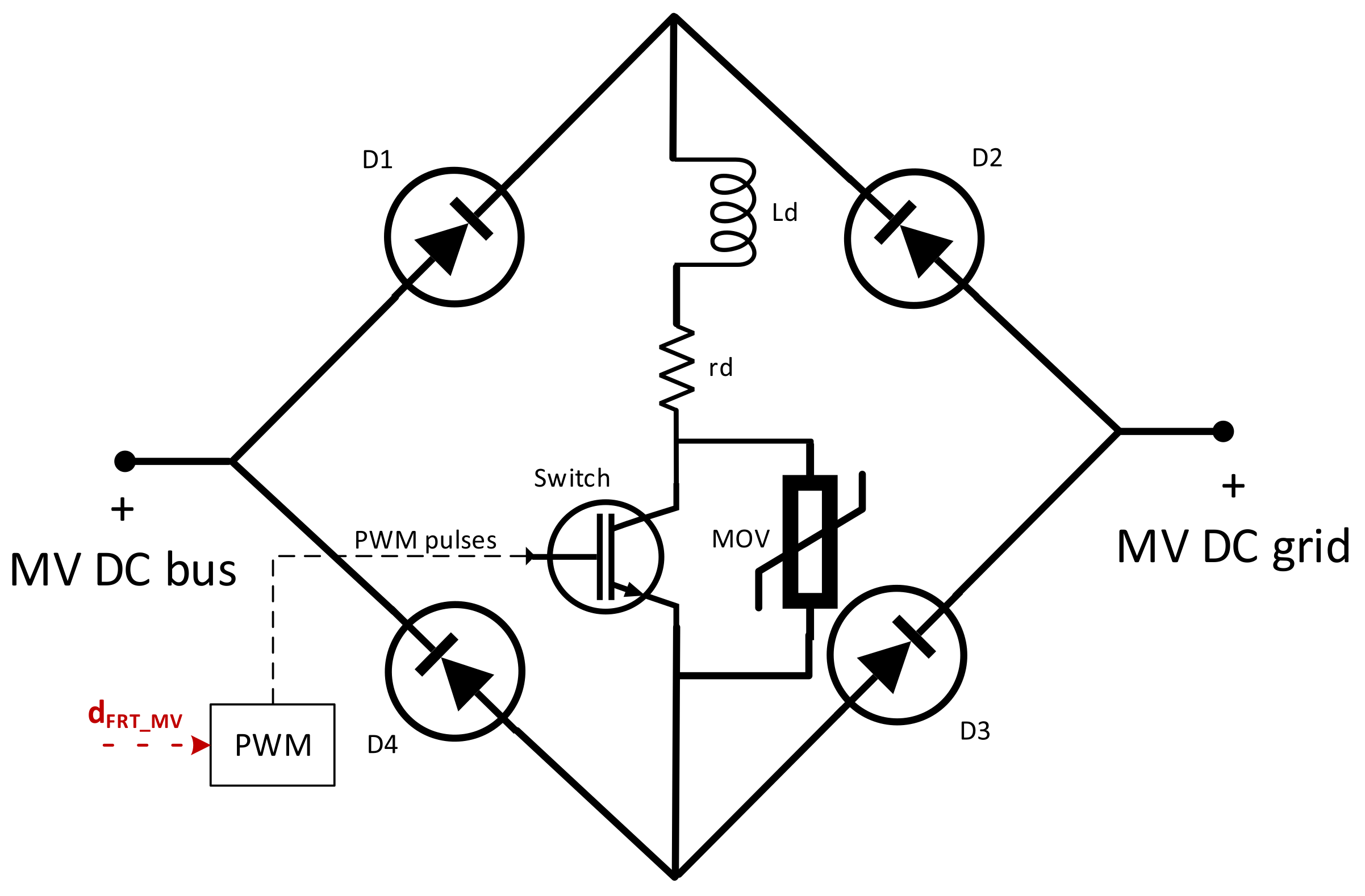
The purpose of the electronic resistor proposed in this work is to provide an additional degree of freedom to control the MC DC grid voltage aiming to support the provision of FRT during AC grid voltage sags without reducing the MV DC bus voltage. By enabling the introduction of a series voltage drop between the MV DC bus and the MV DC grid, the electronic resistor enables the effective reduction of MV DC grid voltage, and thus, the exploitation of its power-voltage sensitivity. A non-isolated bidirectional MV DC/DC converter could be used, but in practice it would represent a more expensive, complex and less energy efficient (in steady-state operation) solution. Instead, the proposed electronic resistor consists of a simpler device inserted in series with the + MV DC line, as depicted in
Figure 2. To the best of the authors knowledge, no electronic resistor specified for this purpose was found in the literature. Nevertheless, taking advantage of the main principles adopted in the design of solid-state Fault Current Limiters (FCL) [
32] and in the design of HVDC breakers [
33], the electronic resistor was conceived and proposed to be integrated in this specific application. The resulting device is depicted in
Figure 5.
The FCL proposed in [
32] provides a simple structure based on a four-diode bridge, a single electronic switching device, an inductor (
and
model the inductance and resistance of the inductor) and a resistor (used for current limiting). The following changes were made to the FCL device described in [
32] in order to obtain an electronic resistor device suited to the purpose intended in this paper. Instead of being operated in on/off operation (no fault/fault conditions), the electronic switch is operated in switching mode at the given switching frequency (
), commanded by a PWM controlled by the duty-cycle signal
generated by the FRT control described in
Section 3. To control the MV DC grid voltage from near zero to
, the current limiting resistor is replaced by a Metal-oxide varistor (MOV), whose impedance is much higher than the equivalent impedance of the MV DC grid for a MOV voltage below its clamping voltage, but much lower that the equivalent impedance of the MV DC grid for a MOV voltage above its clamping voltage. The inductance is dimensioned considering
in order to reduce the current ripple to acceptable magnitudes. The MOV ensures a path for the inductor’s current during electronic switch’s off-state (
), protecting the switching device from voltage surges originated by the inductor. The effectiveness of a MOV in this role is shown in [
33].
In comparison with the high voltage values of the MV DC bus, the forward voltage drop in the four-diode bridge and in the electronic switch during its on-state (
) are much smaller, to the point of being negligible. Thus, the voltage drop in the electronic resistor can be approximated by Equation (
5), where
is the voltage drop in the electronic resistor,
the voltage drop in the inductor,
the voltage drop in the MOV,
is the on-state period of the electronic switch, and
is the off-state period of the electronic switch.
and
are related to the switching period
and switching frequency
according to Equation (
6).
A clamping voltage equal to
was considered for the MOV. Considering an inductor dimensioned to not allow a ripple current above 5% of the ST’s nominal current, a relatively constant current will flow through the MOV during the off-state of the electronic switch, thus originating a voltage at the MOV’s terminals approximately equal to
. A relatively constant current in the inductor also means a relatively constant voltage in the MV DC grid (
) during the switching interval
, assuming the impedance in the MV DC grid does not change significantly in that period. Given this, and considering that the voltage in the MV DC bus (
) is kept close to
, the relationship between
and
can be expressed by Equation (
7), which originate Equations (
8) and (
9), where
is the equivalent impedance of the MV DC grid (which depends on the connected loads and resources).
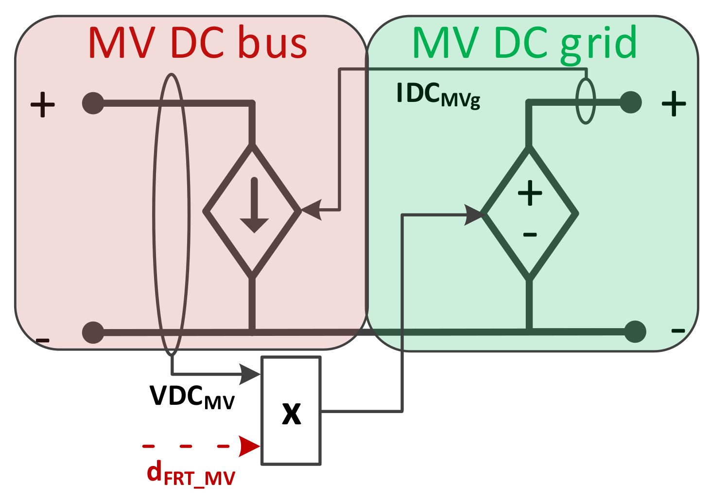
Employing the DAM approach to the model depicted in
Figure 5, the modulation mechanisms can be neglected without relevant impacts in the dynamics of the electronic resistor [
30] since average voltage and current values are determined for each switching period. As a result, given Equation (
9) and that input and output currents of the electronic resistor are equal to
, the electronic resistor can be modeled using controlled voltage and current sources as illustrated in
Figure 6.
2.1.4. Dump Load
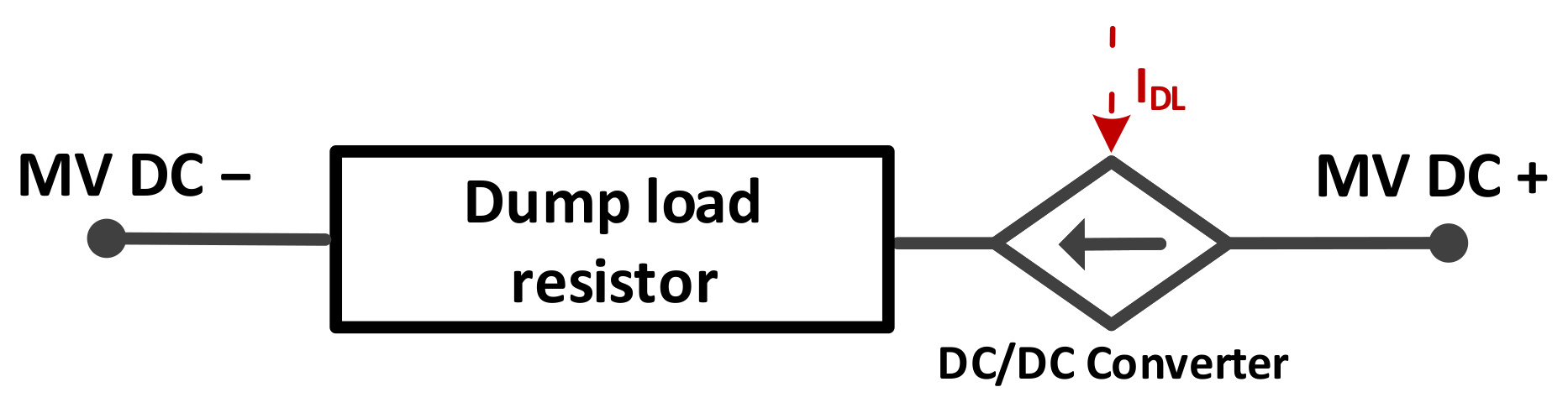
The purpose of the dump-load is to dissipate excessive net generation originated from the hybrid AC/DC network that cannot be delivered to the main power system through the ST’s MV inverter. This may happen when the ST’s MV inverter reaches its technical current limits, namely during fault disturbances in the upstream power system. The dump-load is connected to the ST’s MV DC link and is controlled by the FRT Control described in detail in
Section 3. The dump-load is modeled as illustrated in
Figure 7. Given the DAM technique was adopted, the electronic converter controlling the power flow in the dump-load’s resistor was modeled using a controlled current source.
2.1.5. Supercapacitor Bank
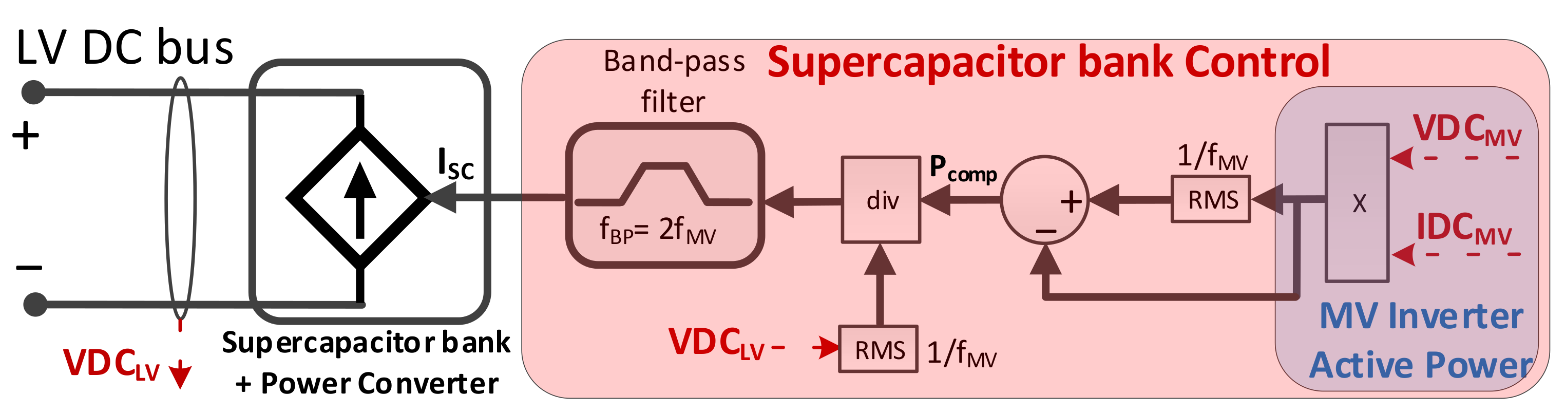
The supercapacitor bank aims to mitigate power oscillations (and thus DC voltage oscillations) in the ST’s DC buses which may result from the occurrence of unbalanced voltage sags in the MV AC grid. The justification for a supercapacitor bank for this purpose is explained in
Section 3. The computational model developed for the supercapacitor bank is depicted in
Figure 8. The modeling of the supercapacitor bank itself is neglected, based on two considerations. First, it is assumed that its internal dynamics is much faster than the dynamics of the power converter interfacing it with the LV DC bus. Second, as shown in
Section 4.1, the energy storage and output power capacities required to address the aforementioned power oscillations can be met by a relatively small supercapacitor bank with a margin sufficiently high to neglect the modeling of any energy and power constraints affecting the supercapacitor bank. Given this, and based on the adopted DAM technique, the supercapacitor bank is modeled as a controlled current source, which represents its interface power converter.
The active power compensation delivered to the LV DC bus occurs through the current
, obtained from Equation (
10) in the Laplace s-domain. In Equation (
10), a second-order band-pass filter captures the power oscillations resulting from the negative-sequence component present in the MV AC grid, using the error between the instantaneous active power in the ST’s MV inverter (
) and the active power related to the positive-sequence component in the MV AC grid (
) given by the RMS of
over the time period of the fundamental frequency in the MV AC grid (
).
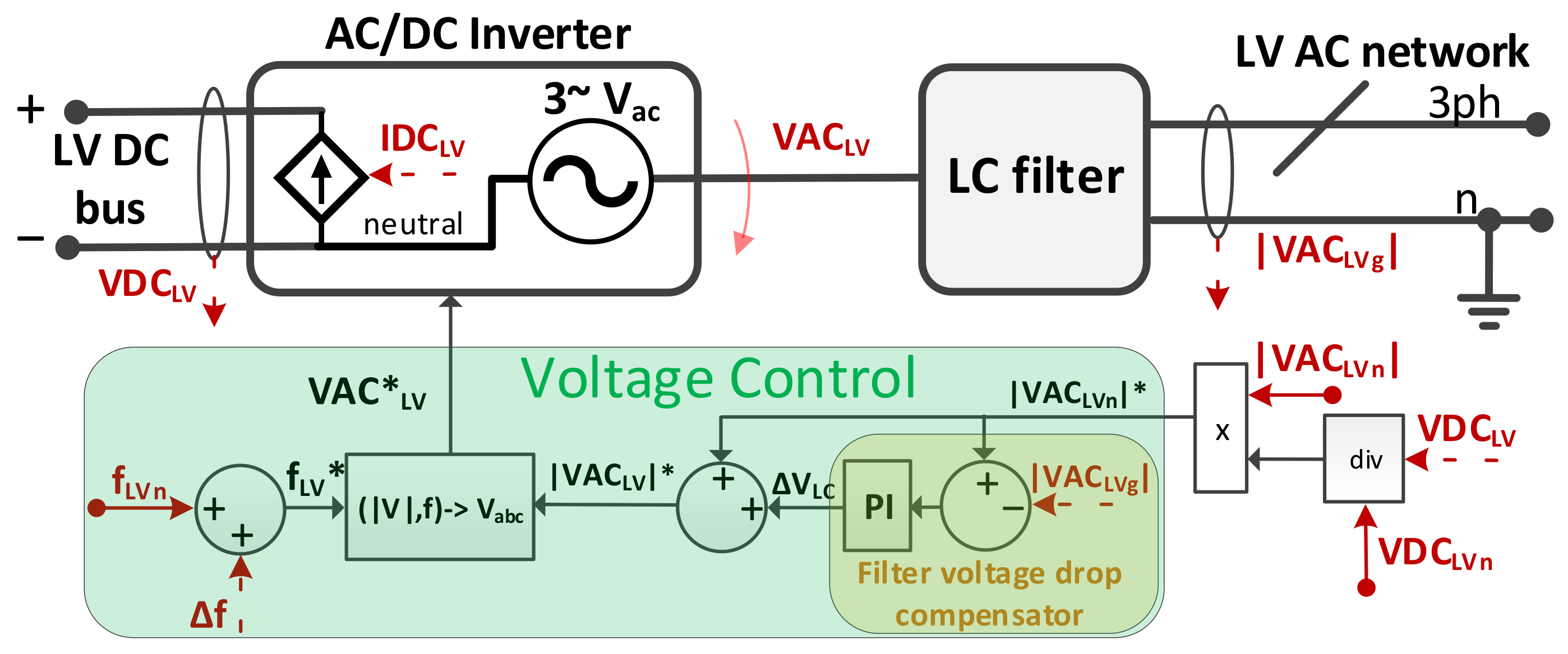
2.1.6. Low Voltage Inverter
The model of the ST’s LV inverter, responsible to generate the LV AC network (grid-forming operation), is represented in
Figure 9. The power stage of the MV inverter AC/DC Inverter) and the LC filter are modeled following the assumptions adopted in [
27]. A grounded neutral regime is adopted for the LV AC network.
The active power in the LV inverter is defined by Equation (
11), where
is the DC current exchanged with the LV DC bus,
is the active power in the LV inverter,
is the LV DC bus voltage,
,
and
are the phase-neutral LV AC voltages (in phases
a,
b and
c) in the LV inverter (
), and
,
and
are the AC currents in the LV inverter’s phases
a,
b and
c (
).
is defined by Equation (
12), where
is the capacitance of the LV DC bus, and
,
and
are the DC currents exchanged between the LV DC bus and the isolated DC/DC converter, LV DC network and the supercapacitor bank, respectively.
The LV DC bus voltage is regulated according to Equations (
13)–(
15), obtained combining Equations (
2), (
3), (
9) and (
12). During normal operation conditions (no FRT activation),
is regulated only through
, given that
and
(as explained in
Section 3), and the remaining currents varying according to the load/generation profile in the hybrid distribution grid. When FRT is activated,
becomes saturated, being
regulated through
,
and
(as explained in
Section 3).
Regarding the control structure of the ST’s LV inverter, a three-phase AC voltage (
is generated using the references for the nominal frequency (
) and voltage magnitude (
), plus a frequency adjustment
generated by FRT Control, as expressed by Equation (
16).
is given by the sum of the voltage magnitude set-point (
) defined by Equation (
17), and the component
generated by the Filter voltage drop compensator.
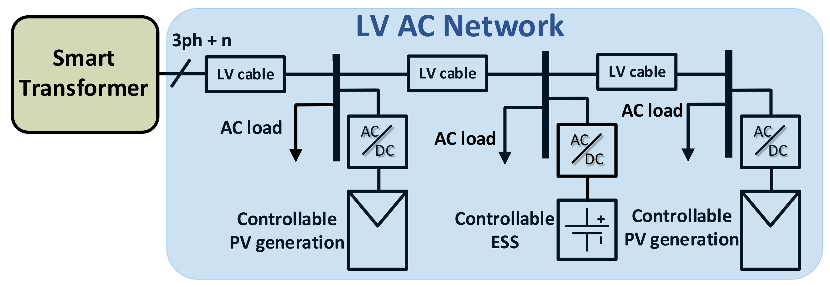
2.2. LV AC Network
The LV AC network integrating the hybrid AC/DC distribution grid adopts the topology described in [
27], represented in
Figure 10. Nevertheless, different power levels for the various elements and load voltage sensitivities were considered. The operation of the PV generation with deloading reserve in normal operation conditions is also adopted.
The exploitation of load-voltage and load-frequency sensitivities in AC networks is already addressed in the literature [
34,
35], as well as their estimation in AC networks using the ST itself [
36,
37]. According to [
38], exponential load models have been the most frequently used static load models by TSOs worldwide. For that reason, Equations (
18) and (
19) are used to model the aggregated active (
P) and reactive (
Q) non-controllable load in the LV AC network, where
and
are respectively the active and reactive loads at the nominal voltage (
) and frequency (
),
is the LV AC network frequency,
and
are respectively the active and reactive power exponents determining the power-voltage load sensitivity, and
and
are respectively the active and reactive power exponents determining the power-frequency load sensitivity.
The parametrization of
and
follows the average value estimations for the entire world presented in [
38]. Regarding
and
, a range of values for residential load in North America is provided in [
38], considered realistic to be used here. The resulting load models are described by Equations (
20) and (
21). The controllable ESS and PV generation were modeled as constant power and constant current devices according to Equation (
22), where
is the module of the output RMS current and
is the nominal RMS current.
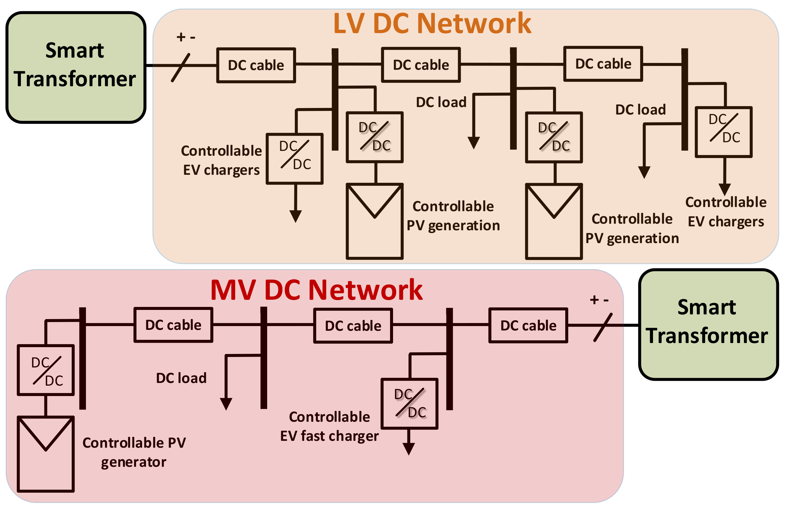
2.3. MV and LV DC Networks
The MV DC and LV DC grids were modeled according to the topologies described also in [
27] and represented in
Figure 11, with the same modifications mentioned in
Section 2.2. Contrary to LV AC grids, the estimation of load voltage sensitivity in DC grids remains largely unexplored in the literature, although several works suggest that a large portion the load in DC grids may consist of constant power loads since it is based on power electronic converters [
39,
40]. Given the lack of data, a scenario with a significant ratio of constant power loads presented in [
37] is adopted. In this paper, this adopted scenario is intended to represent the non-controllable DC loads only, modeled according to Equation (
23) where
is the load power for the nominal voltage (
). The controllable EV chargers and PV generation were modeled as constant power and constant current devices according to Equation (
24), where
is the output current and
is the nominal current.
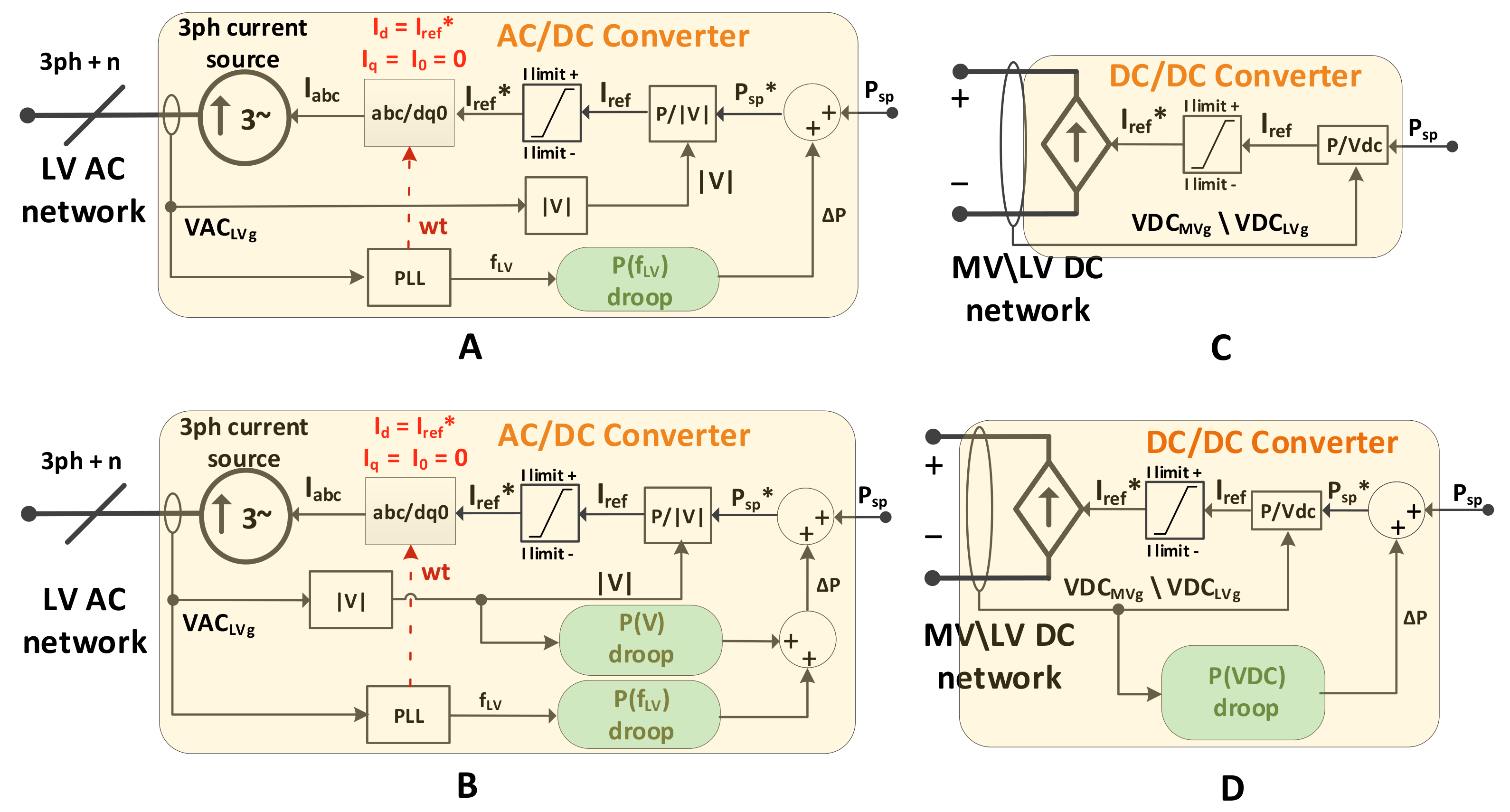
2.4. Distributed Energy Resources
The controllable DER considered in the hybrid AC/DC grid were also modeled following the considerations assumed in [
27], and are illustrated in the block diagrams presented in
Figure 12: The AC/DC Converter for interfacing the PV generator (
Figure 12A) and ESS unit (
Figure 12B) with the LV AC network, and the DC/DC Converter for interfacing the EV chargers (
Figure 12C) and PV generators (
Figure 12D) with the DC networks.
Not being object of study in this paper, reactive power is not considered in the DER units available in the LV AC distribution grid. Thus, the generated reference current (
) represents only the direct current component. PV generation and the ESS in the AC network incorporate an active power–frequency droop (
) in order to respond to the frequency deviations induced by the FRT Control described in
Section 3. The ESS in the AC network also incorporates an active power–voltage droop (
) in order to respond to voltage modulations originated by the FRT Control. PV generation in DC networks incorporates an active power–voltage droop (
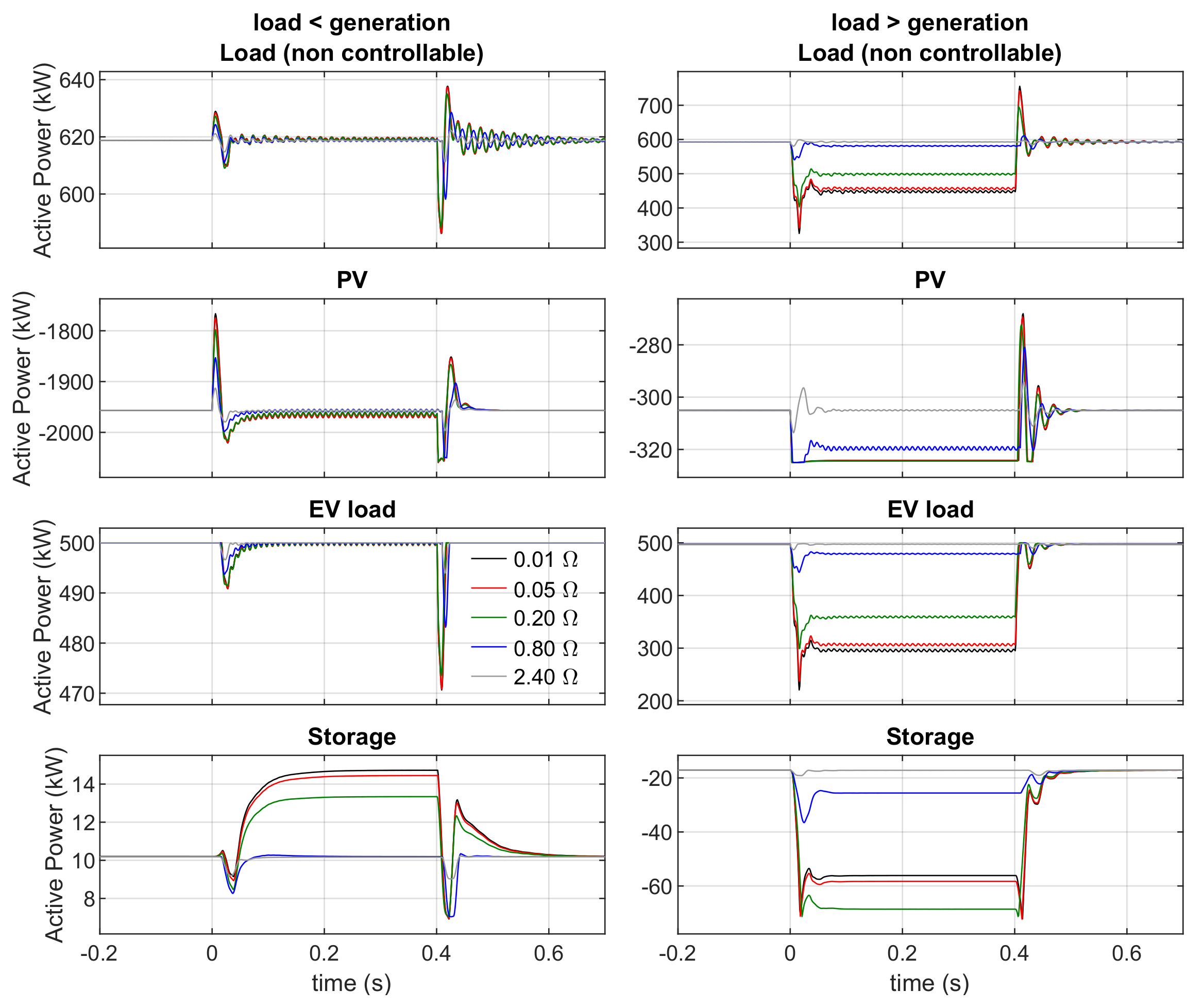
P(VDC)) in order to respond to the voltage deviations induced by the same FRT Control. PV generation operates with 10% of deloading reserve, which is activated in case of under-voltage (DC networks) or under-frequency (LV AC network).
3. Fault-Ride-Through Control
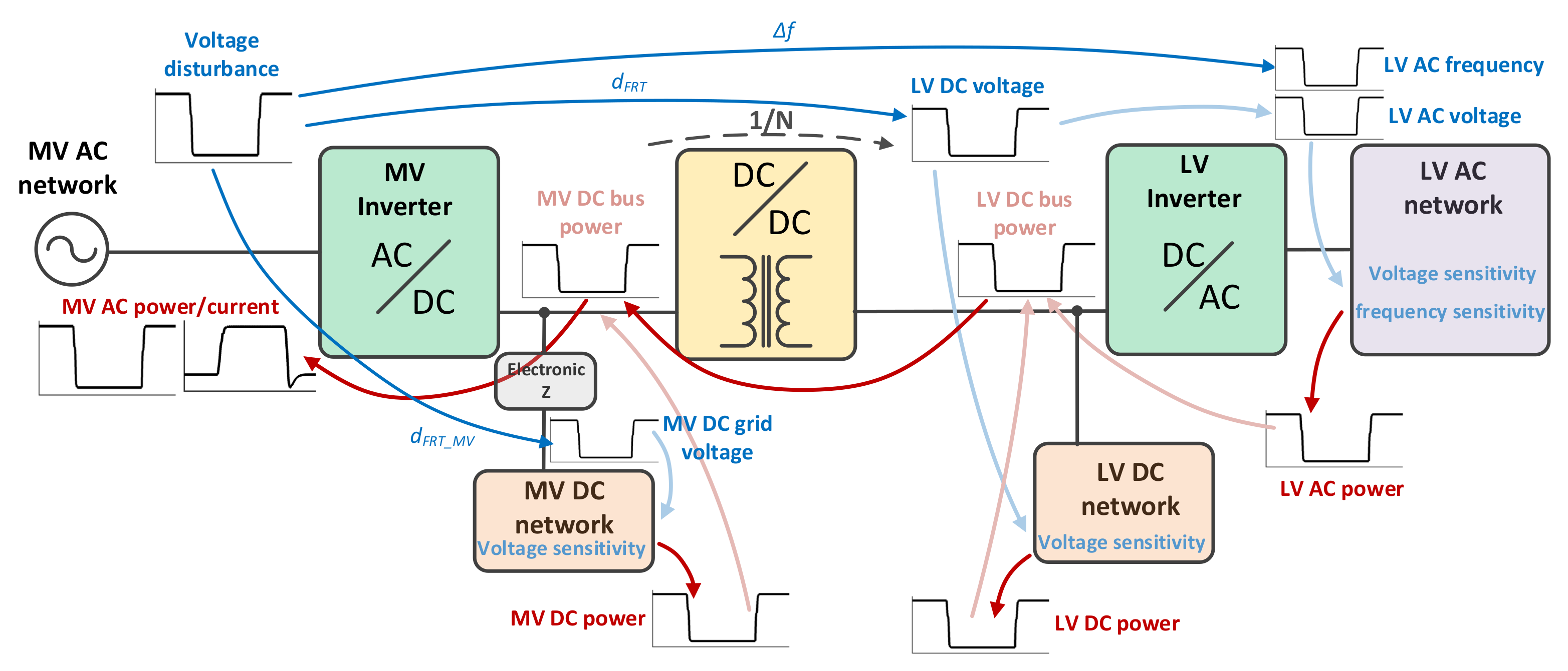
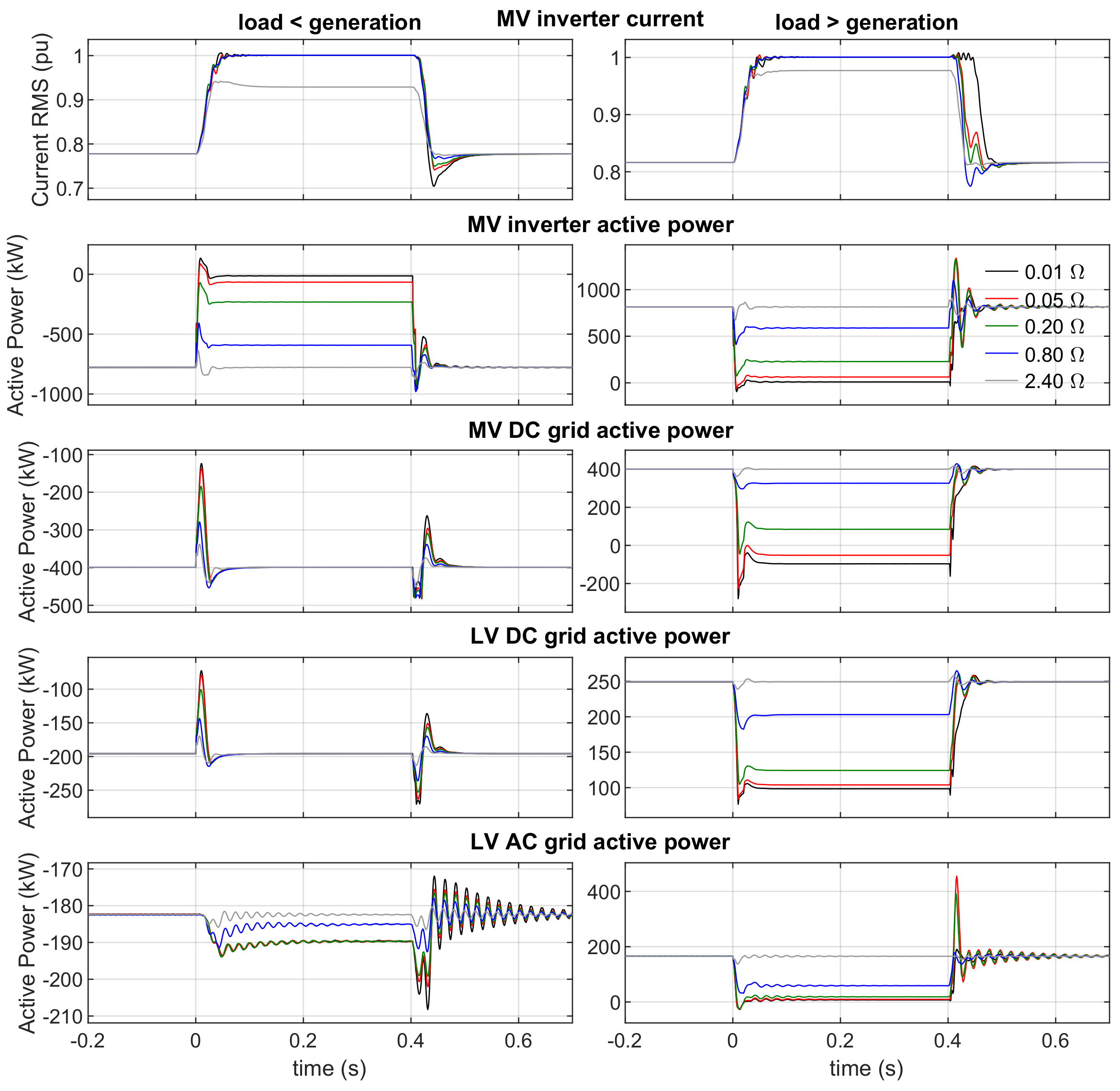
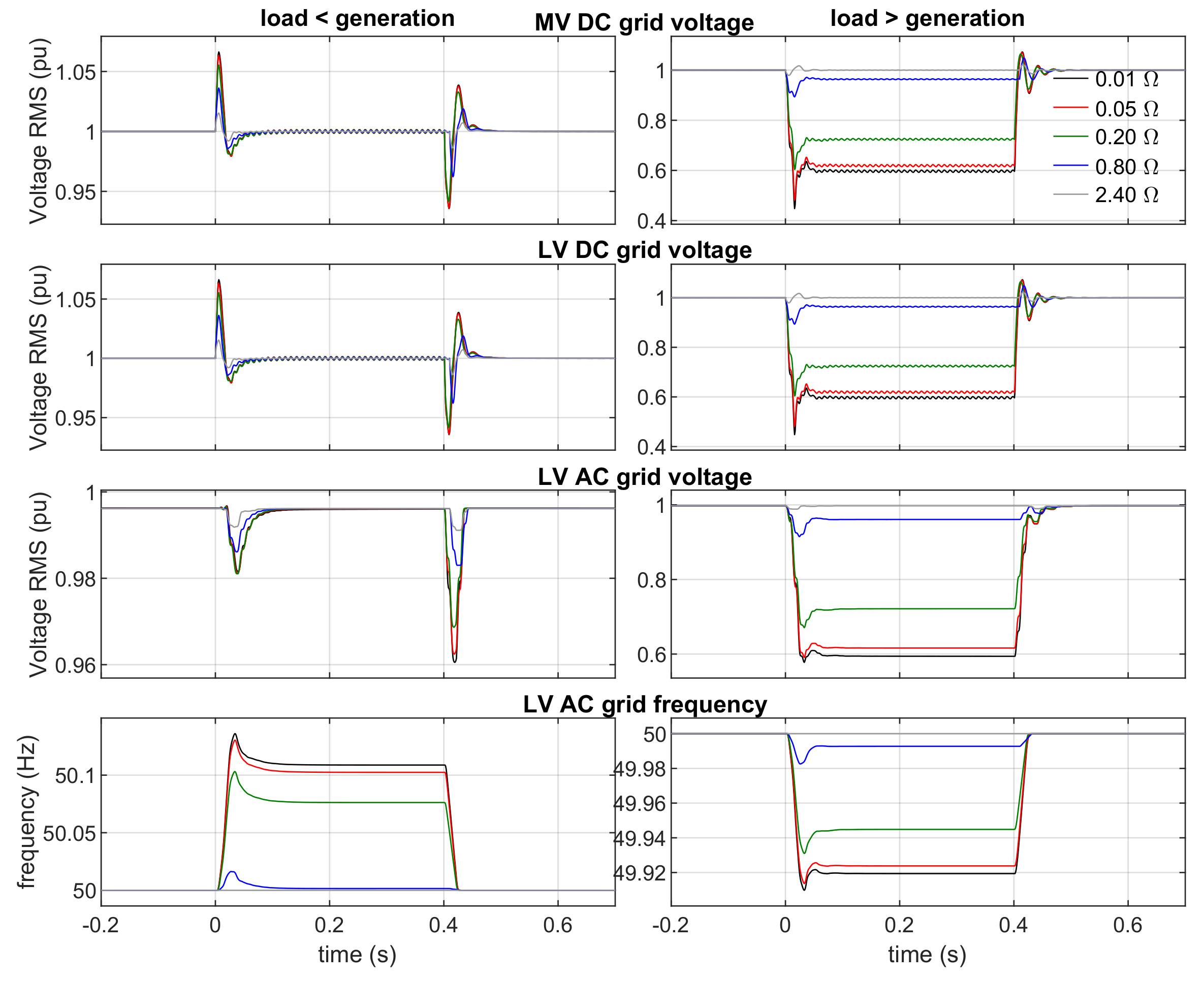
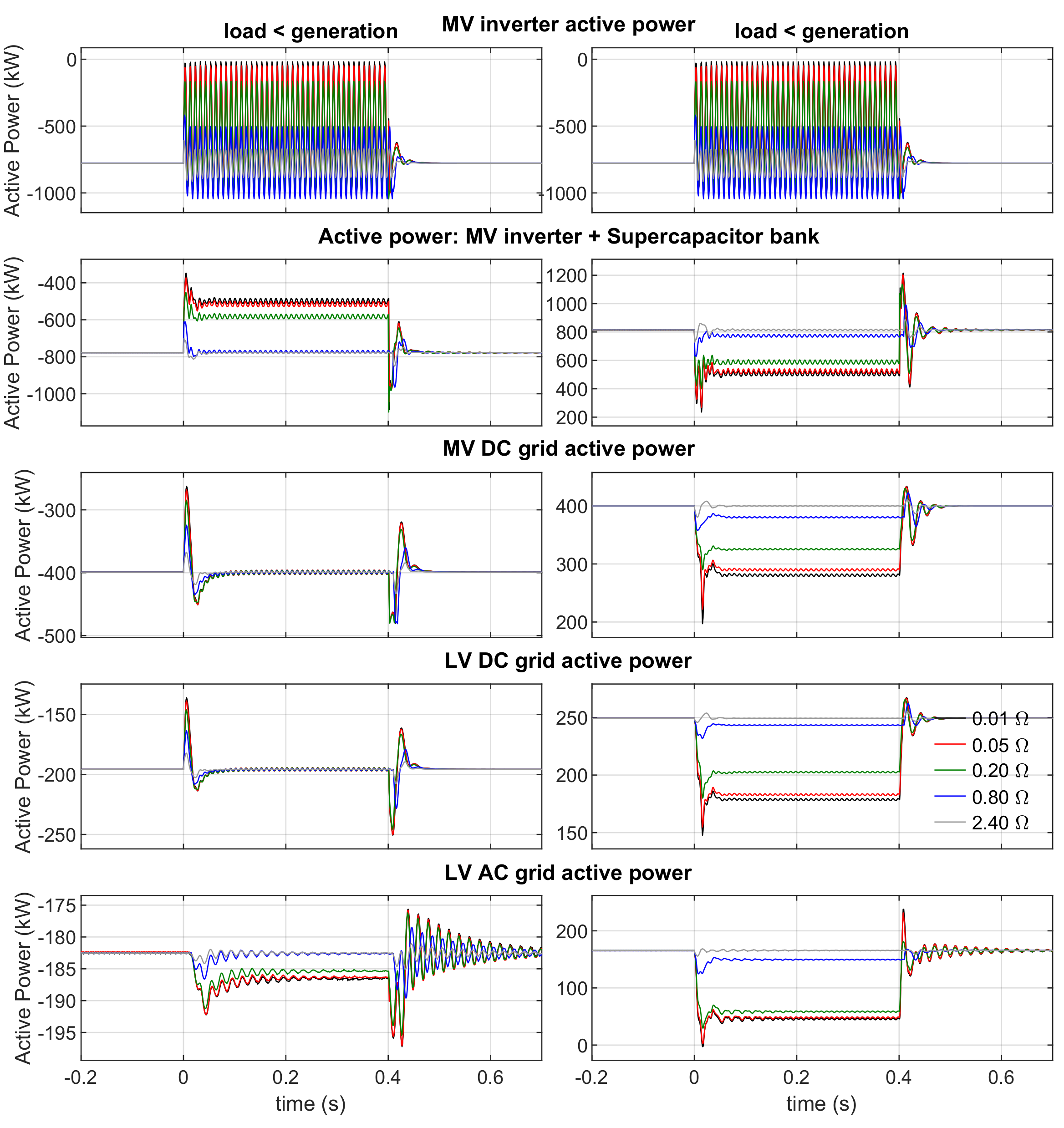
Suited for grid-tied ST with no local energy storage capacity, the underlying rationale of the proposed FRT strategy consists in diverting and/or eliminating excessive net active power (load or generation) from the ST’s hybrid AC/DC network that cannot be balanced by the ST’s MV inverter without violating its current limits. Different operation modes are used for net load scenarios and net generation scenarios in the hybrid AC/DC grid.
For net load scenarios in the hybrid AC/DC grid, the cascading reaction of the proposed FRT strategy is illustrated in
Figure 13. A voltage sag in the MV AC grid causes the FRT control to modulate the voltage and frequency levels in the hybrid AC/DC grid, if the ST’s MV inverter is not capable to balance the power in the hybrid AC/DC grid without violating its current limits. The modulation of the voltage and frequency levels in the hybrid AC/DC grid is aimed to exploit the voltage-power and frequency-power sensitivities of the hybrid AC/DC grid (including voltage-power and frequency-power sensitive modes of DER connected downstream from the ST) in order to reduce the net active power consumption in the hybrid AC/DC network. As a result, the active power in the hybrid AC/DC network that cannot be balanced by the ST’s MV inverter is eliminated. The participation of the MV DC sub-network in this process is made possible by the electronic resistor incorporated in series between the ST’s MV DC bus and the MV DC sub-network. The modeling of the electronic resistor proposed for this purpose is presented in
Section 2.1.3.
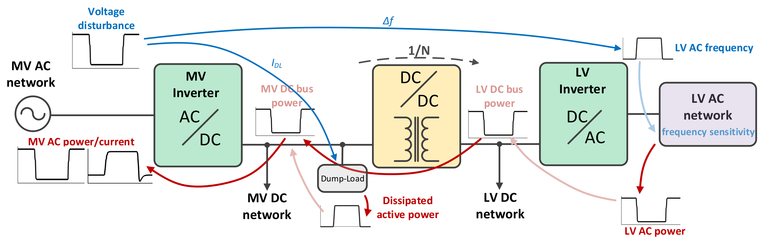
The cascading actuation of the proposed FRT strategy during net generation scenarios in the hybrid AC/DC grid is illustrated in
Figure 14. If the ST’s MV inverter is not capable to balance all the net active power in the hybrid AC/DC grid during the occurrence of a voltage sag in the MV AC grid, the FRT control will modulate the frequency in the LV AC sub-network (using a proportional gain, as shown in
Figure 15 and expressed in Equation (
27)) and also command the dump-load to dissipate net active power in excess. The modulation of the frequency in the LV AC sub-network aims to exploit the frequency-power sensitivity of the LV AC sub-network and of power-frequency sensitive DER located in the LV AC sub-network in order to decrease power generation and increase power consumption in the LV AC sub-network. As a result, the active power in the hybrid AC/DC network that the ST’s MV inverter cannot balance is eliminated. The modeling of the dump-load for the aforementioned purpose is presented in
Section 2.1.4.
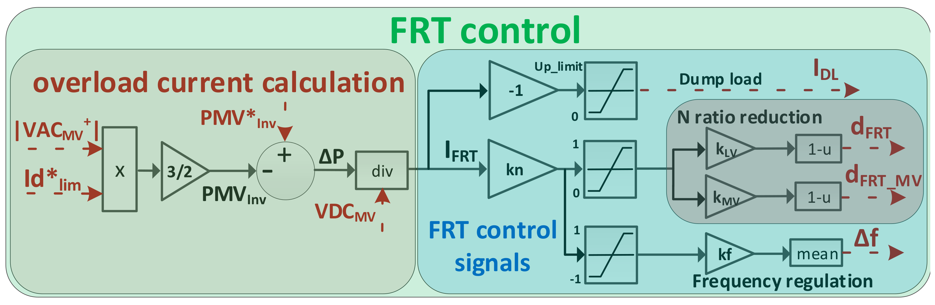
As shown in
Figure 13 and
Figure 14, the operation of the proposed FRT strategy relies on
,
,
and
signals. These signals are generated by the FRT control whose structure is depicted in the block diagram presented in
Figure 15.
,
,
and
signals depend on the reference signal for the MV inverter overload current
, which is calculated according to Equation (
25), where
is the voltage in the MV DC bus,
is the maximum instant active power in the MV inverter,
is the unrestricted reference for the active power (generated by the
VDC Control / P Control illustrated in
Figure 3),
is the magnitude of the positive sequence component of the MV AC voltage measured at the ST’s MV inverter (
Figure 3)) and
is the limited reference for the direct current component (generated by the Current Control illustrated in
Figure 3).
The FRT mechanism is activated when the overload current (
) is non-zero. While the proposed FRT control strategy relies solely in proportional gains to calibrate the response of each four control signals, it is capable to eliminate the steady-state error due to the dependence of
on the PI controller responsible to generate
(see VDC Control / P Control in
Figure 3).
The occurrence of unbalanced voltage sags in the MV AC grid may induce an oscillatory active power component in the MV inverter, here denominated by , which is a result of a negative-sequence component in the MV AC grid voltage. propagates to the MV DC bus, introducing voltage oscillations in the hybrid AC/DC grid, whose compensation effort by VDC Control / P Control will originate an oscillatory component in .
Using the ST’s MV inverter to compensate (by injecting a negative-sequence component current) may imply severe reductions in the transferable active power (positive-sequence component) through the ST’s MV inverter during severe unbalanced voltage sags in the MV AC grid. As a result, this approach could result in adverse impacts on the hybrid AC/DC grid as the proposed FRT mechanism promotes the power balance within the hybrid AC/DC grid.
could also be mitigated by increasing the capacitance in the ST’s DC buses, but unrealistic bulky capacitors would be required in order to achieve an acceptable maximum limit for the DC voltage ripple. Additionally, this solution would significantly degrade the dynamics of the ST itself.
To avoid the drawbacks of the aforementioned solutions, an electronically controlled supercapacitor bank, described in
Section 2.1.5, was incorporated as part of the proposed FRT strategy. Besides preserving the transferable power in the ST’s MV inverter, it also preserves the dynamics of the ST because it only actuates against power oscillations associated to the negative-sequence component, as explained in
Section 2.1.5. Based on [
41], the maximum voltage ripple (
) for the ST’s MV DC bus voltage can be expressed by Equation (
26), where
M is the modulation index of the ST’s MV inverter,
is the maximum amplitude of the active power oscillation associated to the negative-sequence component of the MV AC grid voltage,
is the MV AC grid frequency,
is the maximum amplitude of the negative-sequence component of the MV AC grid voltage,
and
are the capacitances of the ST’s MV and LV DC buses respectively,
is the capacitance of the supercapacitor bank, and
is the supercapacitor bank voltage.
Still, it is also necessary to prevent the amplification of the aforementioned power and voltage oscillations in the hybrid AC/DC grid by the FRT control during unbalanced voltage sags in the MV AC grid. For that reason, is used to calculate in order to obtain an active power limit for the ST’s MV inverter based on the positive-sequence component of the MV AC grid voltage.
3.1. Elimination of Excessive Net Generation
The elimination of excessive net generation in the hybrid AC/DC grid is mainly performed by the dump-load, controlled by the
signal.
is set to zero in normal conditions (
) or during excessive net load in the hybrid AC/DC grid (
). If
, an excess of net generation in the hybrid AC/DC network exists, and a non-zero
signal (
is generated, forcing the dump-load (described in
Section 2.1.4) to dissipate the active power in excess.
Additionally, if
, a nonzero
is also generated, which enables any controllable power-frequency sensitive DER located in the LV AC network to actively contribute to the active power balancing problem by modulating the power output as a function of the LV AC grid frequency in order to reduce the amount of net generation.
is added to the nominal frequency of the LV AC grid (
), as depicted in
Figure 9, and is given by Equation (
27), where
is a gain to regulate the sensitivity of the FRT control to
, and
is a droop gain to adjust
in order to best exploit the existing frequency-controllable DER available in the LV AC sub-network (see
Figure 15).
is set to 0 in normal conditions (
).
3.2. Elimination of the Excessive Net Load
The elimination of the excessive net load in the hybrid AC/DC grid is performed by the combined actuation of
,
and
signals. The
and
signals are set to 1 in normal conditions (
) or during excessive net generation in the hybrid AC/DC grid (
). As a result, the transformation ratio in the isolated DC/DC converter remains in its default value (
), and the electronic resistor (described in
Section 2.1.3) is not actuating (the voltage in the MV DC grid (
) follows the voltage in the MV DC bus (
)). When
,
reduces the transformation ratio in the isolated DC/DC converter and
controls the electronic resistor to insert a series resistance in the connection point of the MV DC grid with the ST’s MV DC bus. As a result the voltages in the LV DC grid (
) and MV DC grid (
) are reduced, according to Equations (
28) and (
29) respectively.
The sensitivity of
and
to
can be adjusted using the gain
(see
Figure 15). The relative contribution of
and
can be adjusted using the gains
and
respectively, with real values between 0 and 1 (see
Figure 15). Equal values for
and
means that
and
will originate similar per unit voltage reductions in their respective sub-networks.
also affects the magnitude of the LV AC grid voltage given its dependence on
as depicted in
Figure 9. Thus, by reducing
and
, the FRT mechanism aims to reduce the active power load in the LV DC and LV AC grids by exploiting their power-voltage sensitivity.
Regarding the
signal, its actuation mechanism is as already described in
Section 3.1.
5. Conclusions
The work presented in this paper addresses the presentation and discussion of a novel FRT control strategy suited for ST with no local energy storage capacity. Four important improvements comparatively to previously proposed FRT control strategies are exposed in this paper: The participation of the MV DC sub-network of the hybrid AC/DC grid, the use of frequency modulation to control the active power output in DER located in the LV AC sub-network of the hybrid AC/DC grid, the dissipation of excessive net generation in the hybrid AC/DC grid to a dump-load, and the use of a electronically controlled supercapacitor bank to compensate active power oscillations in the ST’s DC buses resulting from unbalanced faults in the upstream AC power grid.
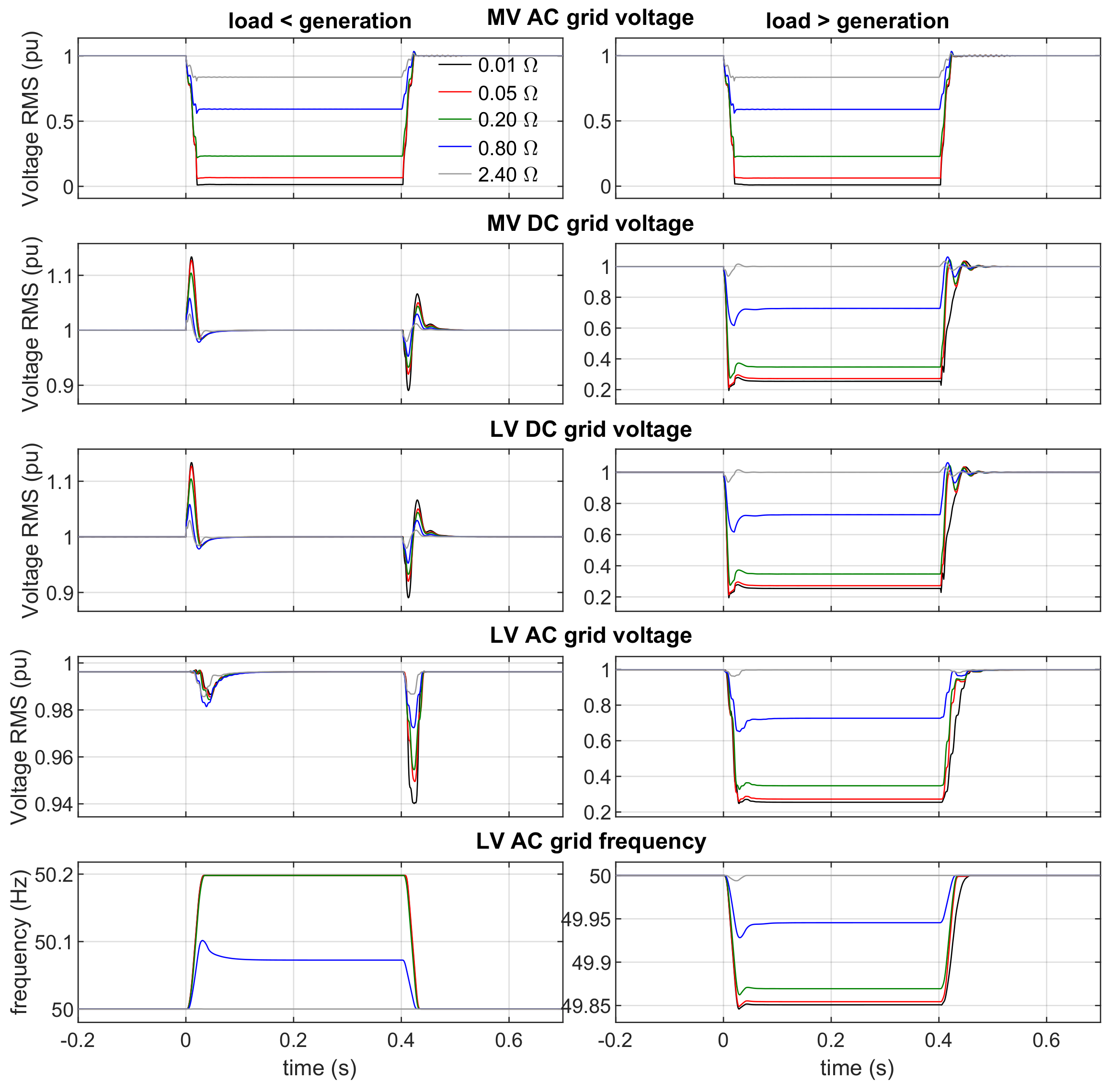
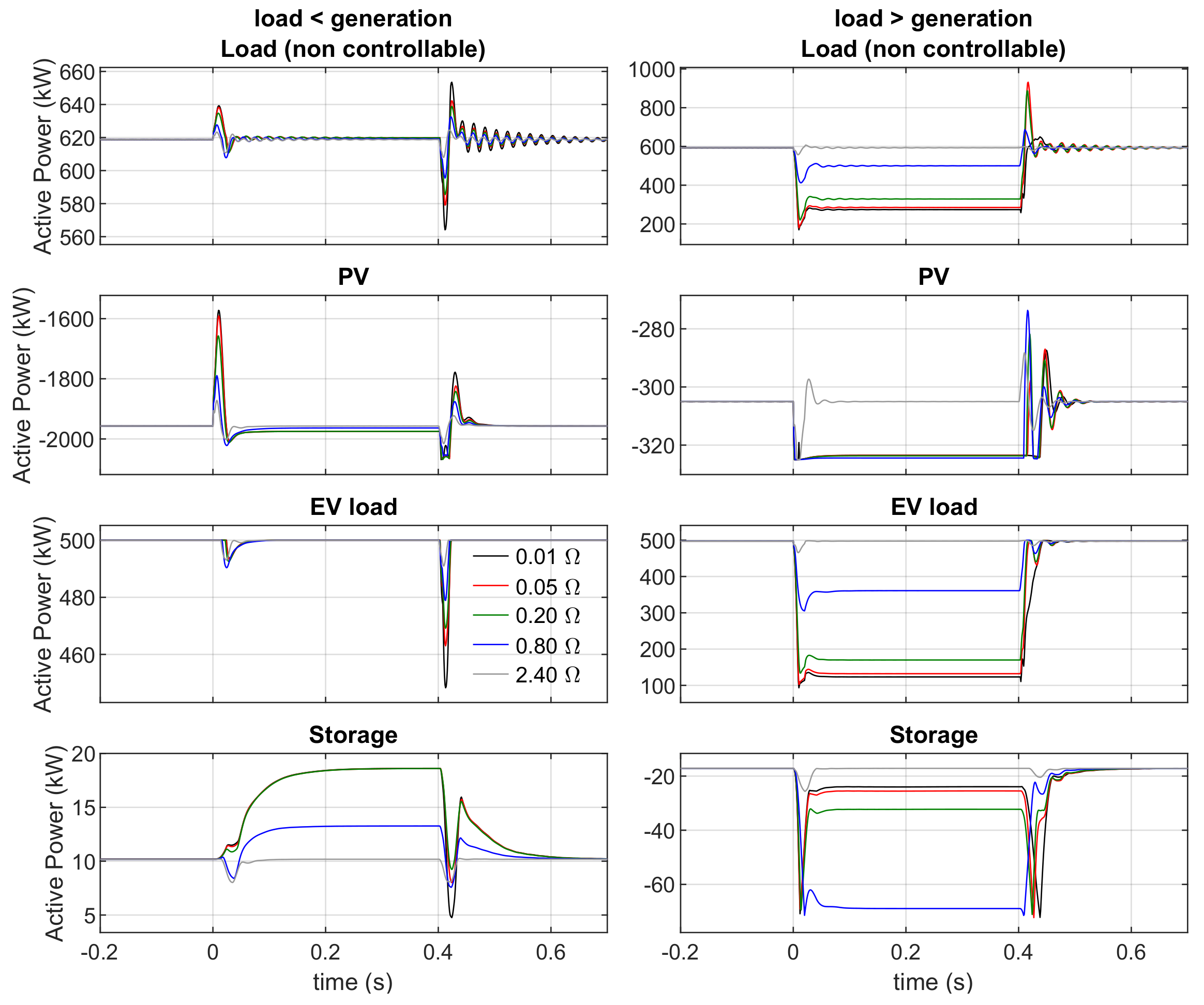
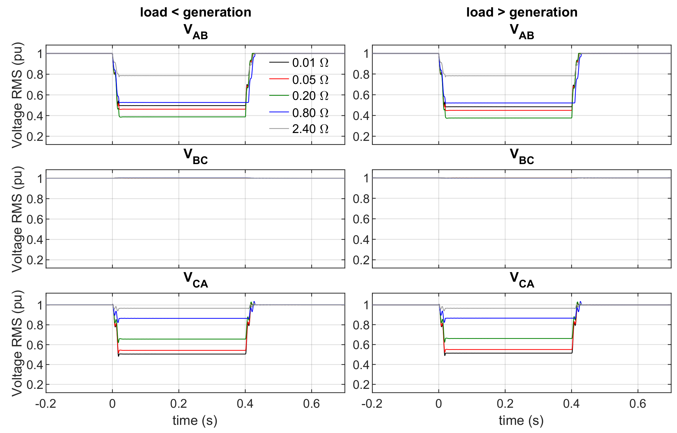
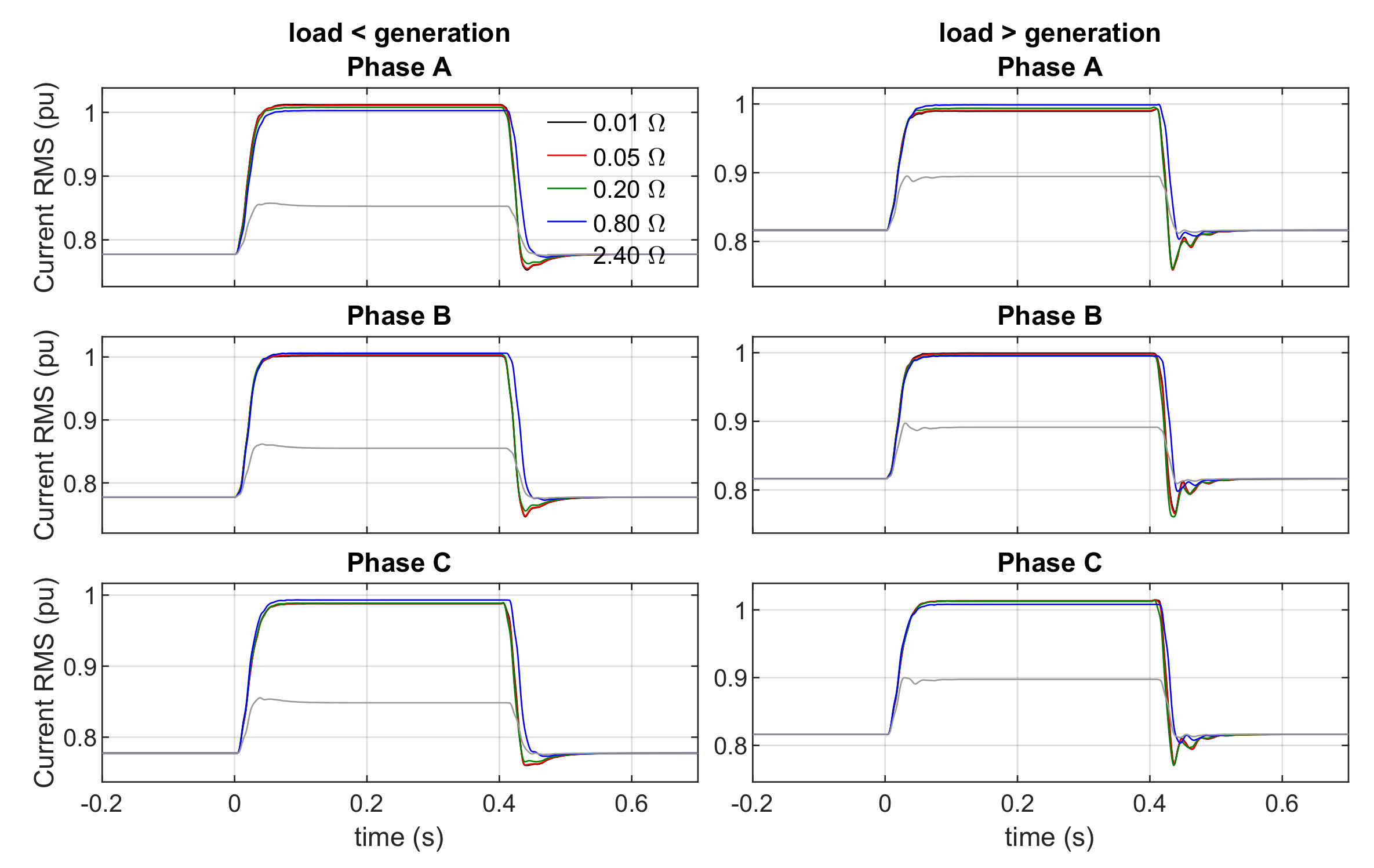
The effectiveness of the proposed strategy is demonstrated for balanced three-phase voltage sags and unbalanced phase–phase and phase-ground voltage sags, while considering also net load and net generation scenarios in the ST’s hybrid AC/DC distribution grid. During net generation scenarios, the proposed FRT control strategy relied successfully on a dump-load do dissipate the excessive net generation in the hybrid AC/DC network, but also exploited the energy storage capacity available in the hybrid AC/DC grid to absorb part of the generation in excess. Regarding net load scenarios, the proposed FRT control strategy modulated the electrical quantities in the hybrid AC/DC grid (voltages in DC and LV AC grids and frequency in LV AC grid), thus exploiting its power-voltage and power-frequency sensitivities in order to eliminate its excessive net load. It also took advantage of PV generation with deloading reserve to reduce the net load in excess, and of energy storage capacity available in the hybrid AC/DC grid which also actively participated in the process by reducing their charging power or by injecting more power to the hybrid AC/DC grid. It is also demonstrated that active power oscillations in the ST’s DC buses resulting from unbalanced faults in the upstream AC power grid can be successfully mitigated.
The proposed FRT approach addresses a research gap with great relevance in future scenarios where hybrid AC/DC distribution grids based on ST may play a central role in a context of massive integration of DER in distribution grids. The proposed FRT control strategies aim at exploiting all the available resources connected downstream from the ST together with complementary solutions at the ST level. However, the parametrization of the FRT controller as a function of the existing resources in the hybrid AC/DC distribution network is not addressed. Moreover, computational models for real-time simulation can also be developed using the DAM approach according to [
30], but this subject was not addressed in the scope of this work. These topics remain to be addressed in future works.


