
Thermodynamic Analysis of CNG Fast Filling Process of Composite Cylinder Type IV

 , ,
, ,
Abstract
:1. Introduction
2. Natural Gas Composition
3. CNG Filling Station
4. Thermodynamic Analysis of a CNG Composite Tank (Type IV) Fast Filling Process
- —the mass of natural gas filled for the “last/recent” step;
- —the mass of natural gas filled at the “start” of the filling process;
5. Calculation of Natural Gas Thermodynamic Properties
5.1. Peng–Robinson Equation of State
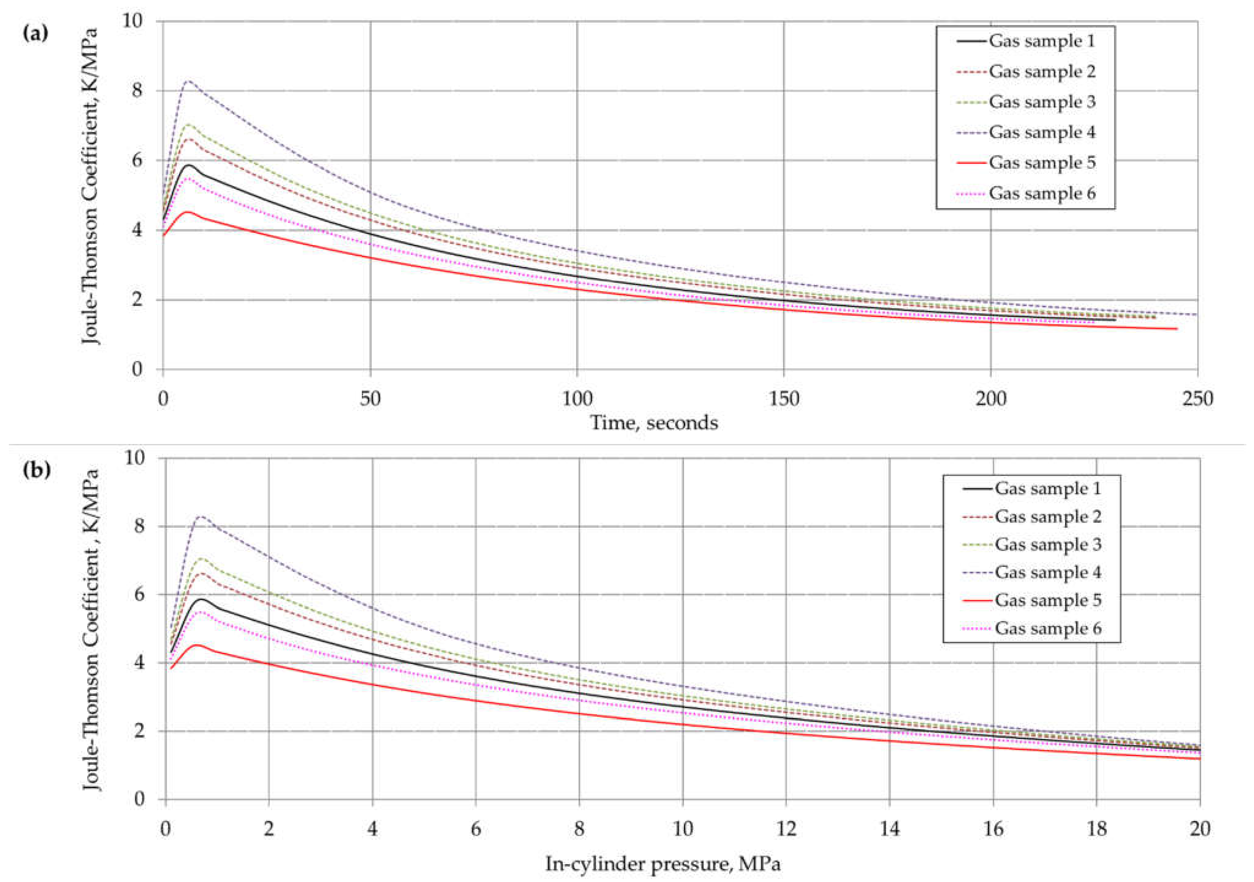
5.2. Enthalpy and Joule–Thomson Coefficient Calculation
- A, B, C, D, E, F, H—empirical coefficients;
- T—temperature [K]/1000;
- hid298.15K— ideal gas enthalpy in 298.15 K;
5.3. Internal Energy Calculation
- um—molar internal energy of real gas;
- —molar internal energy of ideal gas.
6. Results and Discussion
7. Conclusions
Author Contributions
Funding
Acknowledgments
Conflicts of Interest
Nomenclature
| Symbols | |
| A | Area (m2) |
| A, B | dimensionless Peng–Robinson EOS coefficients |
| ai, bi | Peng–Robinson EOS constants |
| Cd | Orifice discharge coefficient |
| Cp | Isobaric heat capacity (kJ/kg·K) |
| Cv | Isochoric heat capacity (kJ/kg·K) |
| g | Gravitational acceleration (m/s2) |
| h | Specific enthalpy (kJ/kg) |
| hm | Molar enthalpy (kJ/kmol) |
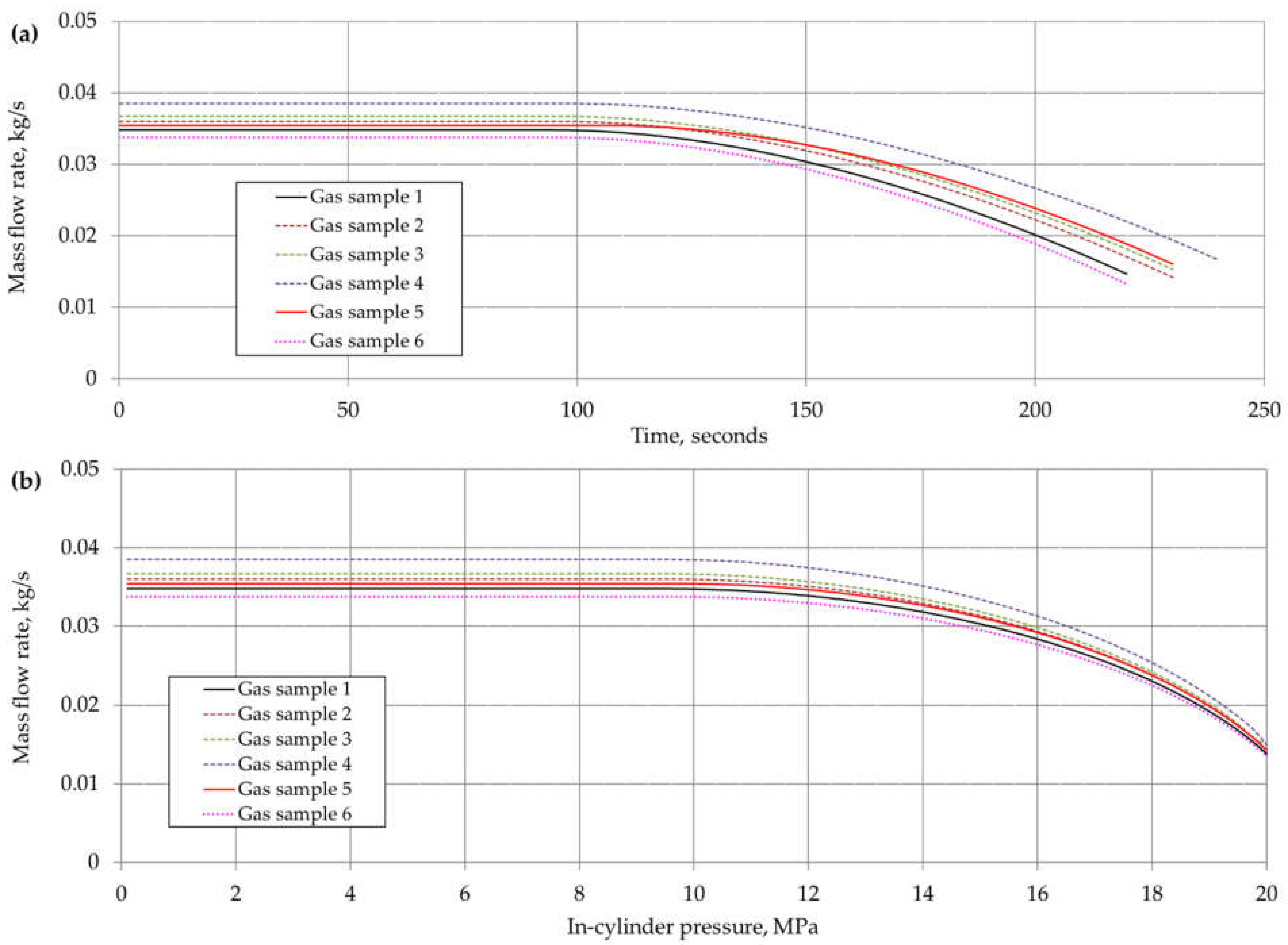
| Mass flow rate (kg/s) | |
| M | Molecular weight (kg/kmol) |
| p | Pressure (bar or Pa) |
| Heat transfer rate (kW) | |
| R | universal gas constant (kJ/(kmol·K) |
| t | Time (s) |
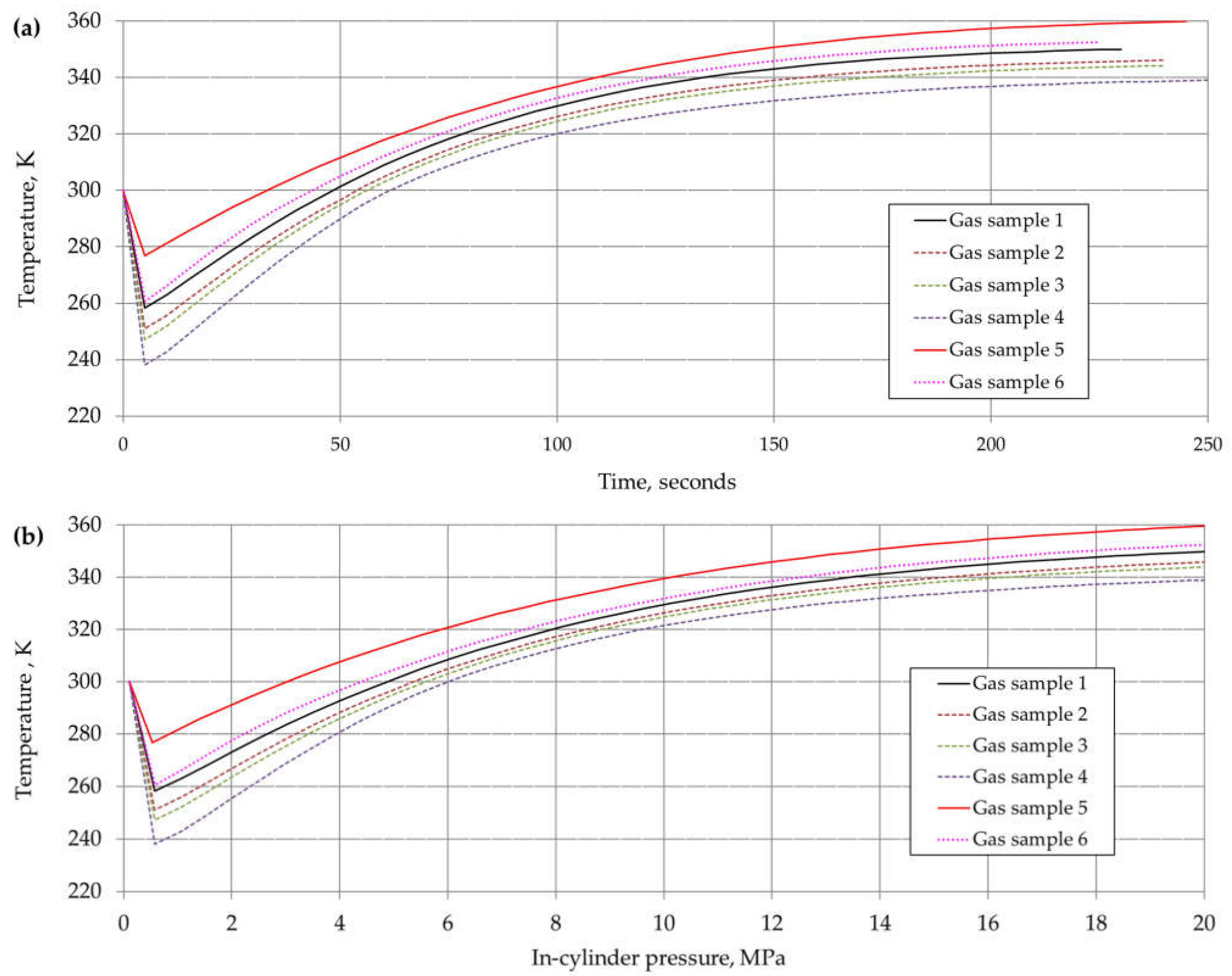
| T | Temperature (K or °C) |
| u | Internal energy (kJ/kg) |
| um | Molar internal energy |
| UHC | Heat transfer coefficient (W/(m2K)) |
| v | Specific volume (m3/kg) |
| vm | Molar specific volume (m3/mol) |
| V | Velocity (m/s) |
| W | Actual work (kJ/kg) |
| Actual work rate (kW or MW) | |
| z | Height (m) |
| Z | Compressibility factor |
| Greek letters | |
| α | Soave alpha function |
| δij | Binary coefficient |
| ρ | Density (kg/m3) |
| ρm | Molar density (mol/m3) |
| ρr | Reduce density |
| γ | Isentropic exponent |
| μJ-T | Joule–Thomson coefficient (K/MPa) |
| ω | Acentric factor |
| Subscripts | |
| C | NGV onboard cylinder |
| cr | Critical |
| cv | Control volume |
| R | Reservoir tank |
| id | Ideal gas |
| I | Initial or inlet condition |
| r | Recent |
| res | Residual |
| S | Start of filling process |
| amb | Ambient |
| av | Average |
References
- Kuczyński, S.; Liszka, K.; Łaciak, M.; Kyć, K.; Oliinyk, A.; Szurlej, A. The impact of the use of alternative fuels in transport, with a particular emphasis on CNG, to reduce the emissions of air pollutants. Polityka Energetyczna—Energy Policy J. 2016, 19, 91–104. [Google Scholar]
- Khan, M.I.; Yasmin, T.; Shakoor, A. Technical overview of compressed natural gas (CNG) as a transportation fuel. Renew. Sustain. Energy Rev. 2015, 51, 785–797. [Google Scholar] [CrossRef]
- Burchart-Korol, D.; Gazda-Grzywacz, M.; Zarębska, K. Research and Prospects for the Development of Alternative Fuels in the Transport Sector in Poland: A Review. Energies 2020, 13, 2988. [Google Scholar] [CrossRef]
- NGV Global. Statistics on Natural Gas Vehicles. Available online: www.ngvglobal.org/ngv-statistics/ (accessed on 26 July 2021).
- IGU. Global Gas Report 2018. In Proceedings of the 27th World Gas Conference, Washington, DC, USA, 23–29 June 2018. [Google Scholar]
- IEA. Natural Gas Information 2020; International Energy Agency: Paris, France, 2020. [Google Scholar]
- PSPA. Rynek Paliw Alternatywnych CNG i LNG. In Polskie Stowarzyszenie Paliw Alternatywnych; PSPA: Warszawa, Poland, 2017. [Google Scholar]
- Nagy, S.; Siemek, J. Shale gas in Europe: The state of the technology-challenges and opportunities. Arch. Min. Sci. 2011, 56, 727–760. [Google Scholar]
- Siemek, J.; Kaliski, M.; Rychlicki, S.; Sikora, S.; Janusz, P.; Szurlej, A. Importance of LNG technology in the development of world’s natural gas deposits. Gospod. Surowcami Miner. 2011, 27, 109–130. [Google Scholar]
- Dorosz, P. Sprężony i skroplony gaz ziemny jako alternatywa dla paliw ropopochodnych wykorzystywanych w transporcie. Polityka Energetyczna—Energy Policy J. 2018, 21, 85–98. [Google Scholar]
- European Parliament and the Council of the European Union, Deployment of Alternative Fuels Infrastructure, Directive 2014/94/EU. 2014. Official Journal of the European Union. Available online: https://eur-lex.europa.eu/legal-content/EN/TXT/?uri=celex%3A32014L0094 (accessed on 30 August 2021).
- European Parliament and the Council of the European Union, Union Guidelines for the Development of the Trans-European Transport Network and Repealing Decision No 661/2010/EU, Regulation (EU) No 1315/2013. 2013. Official Journal of the European Union. Available online: https://eur-lex.europa.eu/legal-content/EN/TXT/?uri=uriserv:OJ.L_.2013.348.01.0001.01.ENG (accessed on 30 August 2021).
- Communication from the Commission. The European Green Deal; European Commission: Brussels, Belgium, 2019; Available online: https://eur-lex.europa.eu/legal-content/EN/TXT/?uri=COM%3A2019%3A640%3AFIN (accessed on 30 August 2021).
- Speirs, J.; Balcombe, P.; Blomerus, P.; Stettler, M.; Brandon, N.; Hawkes, A. Can natural gas reduce emissions from transport. In Heavy Goods Vehicles and Shipping; Sustainable Gas Institute, Imperial College London: London, UK, 2019. [Google Scholar]
- Ogden, J.; Jaffe, A.M.; Scheitrum, D.; McDonald, Z.; Miller, M. Natural gas as a bridge to hydrogen transportation fuel: Insights from the literature. Energy Policy 2018, 115, 317–329. [Google Scholar] [CrossRef]
- International Standard. ISO 11439-2013. Gas Cylinders—High Pressure Cylinders for the On-Board Storage of Natural Gas as a Fuel for Automotive Vehicles; ISO: Geneva, Switzerland, 2013. [Google Scholar]
- European Standard. EN 12245-2011, Transportable Gas Cylinders. Fully Wrapped Composite Cylinders; European Standards: Brussels, Belgium, 2011. [Google Scholar]
- Regulation No 110 of the Economic Commission for Europe of the United Nations (UN/ECE)—Uniform Provisions Concerning the Approval of I. Specific Components of Motor Vehicles Using Compressed Natural Gas (CNG) in Their Propulsion System; II. Vehicles with Regard to the Installation of Specific Components of an Approved Type for the Use of Compressed Natural Gas (CNG) in Their Propulsion System. 2010. Official Journal of the European Union. Available online: https://eur-lex.europa.eu/legal-content/EN/TXT/?uri=CELEX:42011X0507(01) (accessed on 30 August 2021).
- Kountz, K.J. Modeling the fast fill process in natural gas vehicle storage cylinders. In Proceedings of the 207th ACS National Meeting-Division of Fuel Chemistry, San Diego, CA, USA, 13–17 March 1994; Institute of Gas Technology: Chicago, IL, USA, 1994. [Google Scholar]
- Farzaneh-Gord, M.; Deymi-Dashtebayaz, M.; Rahbari, H.R. Studying effects of storage types on performance of CNG filling stations. J. Nat. Gas Sci. Eng. 2011, 3, 334–340. [Google Scholar] [CrossRef]
- Farzaneh-Gord, M. Real and ideal gas thermodynamic analysis of single reservoir filling process of natural gas vehicle cylinders. J. Theor. Appl. Mech. 2011, 41, 21–36. [Google Scholar]
- Deymi-Dashtebayaz, M.; Farzaneh-Gord, M.; Rahbari, H.R. Studying transmission of fuel storage bank to NGV cylinder in CNG fast filling station. J. Braz. Soc. Mech. Sci. Eng. 2012, 34, 429–435. [Google Scholar] [CrossRef] [Green Version]
- Farzaneh-Gord, M.; Deymi-Dashtebayaz, M. Optimizing natural gas fueling station reservoirs pressure based on ideal gas model. Pol. J. Chem. Technol. 2013, 15, 88–96. [Google Scholar] [CrossRef] [Green Version]
- Farzaneh-Gord, M.; Deymi-Dashtebayaz, M.; Rahbari, H.R. Effects of gas types and models on optimized gas fuelling station reservoir’s pressure. Braz. J. Chem. Eng. 2013, 30, 399–411. [Google Scholar] [CrossRef]
- Nahavandi, N.N.; Farzaneh-Gord, M. Numerical simulation of filling process of natural gas onboard vehicle cylinder. J. Braz. Soc. Mech. Sci. Eng. 2013, 35, 247–256. [Google Scholar] [CrossRef]
- Deymi-Dashtebayaz, M.; Farzaneh-Gord, M.; Nooralipoor, N.; Rastgar, S. The full simulation of rapid refueling of a natural gas vehicle on-board cylinder. J. Nat. Gas Sci. Eng. 2014, 21, 1099–1106. [Google Scholar] [CrossRef]
- Farzaneh-Gord, M.; Rahbari, H.R.; Deymi-Dashtebayaz, M. Effects of natural gas compositions on CNG fast filling process for buffer storage system. Oil Gas Sci. Technol.—Rev. D’ifp Energ. Nouv. 2014, 69, 319–330. [Google Scholar] [CrossRef] [Green Version]
- Khamforoush, M.; Moosavi, R.; Hatami, T. Compressed natural gas behavior in a natural gas vehicle fuel tank during fast filling process: Mathematical modeling, thermodynamic analysis, and optimization. J. Nat. Gas Sci. Eng. 2014, 20, 121–131. [Google Scholar] [CrossRef]
- Ramoutar, S.; Riverol, C.A. Thermodynamic analysis of refueling a Natural Gas Vehicle cylinder from a cascade reservoir using chilled natural gas. J. Nat. Gas Sci. Eng. 2017, 38, 298–322. [Google Scholar] [CrossRef]
- Zhang, G.; Brinkerhoff, J.; Li, R.; Forsberg, C.; Sloan, T. Analytical and numerical study on the fast refill of compressed natural gas with active heat removal. J. Nat. Gas Sci. Eng. 2017, 45, 552–564. [Google Scholar] [CrossRef] [Green Version]
- Taccani, R.; Maggiore, G.; Micheli, D. Development of a Process Simulation Model for the Analysis of the Loading and Unloading System of a CNG Carrier Equipped with Novel Lightweight Pressure Cylinders. Appl. Sci. 2020, 10, 7555. [Google Scholar] [CrossRef]
- Liu, J.; Zheng, S.; Zhang, Z.; Zheng, J.; Zhao, Y. Numerical study on the fast filling of on-bus gaseous hydrogen storage cylinder. Int. J. Hydrogen Energy 2020, 45, 9241–9251. [Google Scholar] [CrossRef]
- Dicken, C.J.B.; Merida, W. Modeling the transient temperature distribution within a hydrogen cylinder during refueling. Numer. Heat Transf. Part A Appl. 2007, 53, 685–708. [Google Scholar] [CrossRef]
- Bourgeois, T.; Ammouri, F.; Weber, M.; Knapik, C. Evaluating the temperature inside a tank during a filling with highly-pressurized gas. Int. J. Hydrogen Energy 2015, 40, 11748–11755. [Google Scholar] [CrossRef]
- Deymi-Dashtebayaz, M.; Farzaneh-Gord, M.; Nooralipoor, N.; Niazmand, H. The complete modelling of the filling process of hydrogen onboard vehicle cylinders. Braz. J. Chem. Eng. 2016, 33, 391–399. [Google Scholar] [CrossRef] [Green Version]
- Wang, L.; Zheng, C.; Wei, S.; Wang, B.; Wei, Z. Thermo-mechanical investigation of composite high-pressure hydrogen storage cylinder during fast filling. Int. J. Hydrogen Energy 2015, 40, 6853–6859. [Google Scholar] [CrossRef]
- Khab, H.; Chaker, A.; Ziani, L. Effects of pressure and hydrogen addition to methane on the temperatures within a pressurized cylinder during the vehicle refueling of HCNG. Int. J. Hydrogen Energy 2019, 44, 22437–22444. [Google Scholar] [CrossRef]
- Bourgeois, T.; Ammouri, F.; Baraldi, D.; Moretto, P. The temperature evolution in compressed gas filling processes: A review. Int. J. Hydrogen Energy 2018, 43, 2268–2292. [Google Scholar] [CrossRef]
- Li, H.; Lyu, Z.; Liu, Y.; Han, M.; Li, H. The effects of infill on hydrogen tank temperature distribution during fast fill. Int. J. Hydrogen Energy 2021, 46, 10396–10410. [Google Scholar] [CrossRef]
- Bai, Y.; Zhang, C.; Duan, H.; Jiang, S.; Zhou, Z.; Grouset, D.; Zhang, M.; Ye, X. Modeling and optimal control of fast filling process of hydrogen to fuel cell vehicle. J. Energy Storage 2021, 35, 102306. [Google Scholar] [CrossRef]
- Sadi, M.; Deymi-Dashtebayaz, M. Hydrogen refueling process from the buffer and the cascade storage banks to HV cylinder. Int. J. Hydrogen Energy 2019, 44, 18496–18504. [Google Scholar] [CrossRef]
- Melideo, D.; Baraldi, D.; Acosta-Iborra, B.; Cebolla, R.O.; Moretto, P. CFD simulations of filling and emptying of hydrogen tanks. Int. J. Hydrogen Energy 2017, 42, 7304–7313. [Google Scholar] [CrossRef]
- Kuczyński, S.; Liszka, K.; Łaciak, M.; Olijnyk, A.; Szurlej, A. Experimental Investigations and Operational Performance Analysis on Compressed Natural Gas Home Refueling System (CNG-HRS). Energies 2019, 12, 4511. [Google Scholar] [CrossRef] [Green Version]
- Safronov, A.; Guzeyeva, J.; Begens, J.; Mezulis, A. The Innovative Technology of Hydraulic Compression and Boosting for Filling the Vehicles and Storage Systems with Natural Gas and Biomethane. Environ. Clim. Technol. 2020, 24, 80–93. [Google Scholar] [CrossRef]
- Nagy, S.; Barczyński, A.; Blicharski, J.; Duliński, W.; Łaciak, M.; Marszałek, J.; Ropa, C.E.; Rybicki, C.; Smulski, R.; Ślizowski, J.; et al. Vademecum gazownika tom I. Podstawy Gazownictwa Ziemnego: Pozyskiwanie, Przygotowanie do Transportu, Magazynowanie; Scientific and Technical Association of Engineers and Technicians of the Oil and Gas Industry: Kraków, Poland, 2014. [Google Scholar]
- Nederstigt, P. Real Gas Thermodynamics: And the Isentropic Behavior of Substances. Master’s Thesis, Master of Science in Mechanical Engineering, Delft University of Technology, Delft, The Netherlands, 2017. [Google Scholar]
- Peng, D.Y.; Robinson, D.B. A New Two-Constant Equation of State. Ind. Eng. Chem. Fundam. 1976, 15, 59–64. [Google Scholar] [CrossRef]
- Chase, M. NIST-JANAF Themochemical Tables, 4th ed.; American Chemical Society and the American Institute of Physics for the National Institute of Standards and Technology: New York, NY, USA, 1998; pp. 1–1951. [Google Scholar]
- Moran, M.J.; Shapiro, H.N. Fundamentals of Engineering Thermodynamics, 6th ed.; John Wiley & Sons Inc.: Hoboken, NJ, USA, 2007. [Google Scholar]
- Tsuchiya, M.; Ogasa, H.; Matsuura, H.; Shimanuki, H.; Fujii, I. Thermodynamic Behavior of Supply Gas and Influence on Vehicle Fuel Fill Line during CNG Fast Fill; SAE Technical Paper 961173; SAE International: Warrendale, PA, USA, 1996. [Google Scholar]


| Component | Chemical Formula | Gas Sample No. | |||||
|---|---|---|---|---|---|---|---|
| 1 | 2 | 3 | 4 | 5 | 6 | ||
| Concentration, [% Mol] | |||||||
| methane | CH4 | 100 | 96.2 | 93.3 | 90 | 80.3 | 97 |
| ethane | C2H6 | - | 2.6 | 6.3 | 6.5 | 0.3 | - |
| propane | C3H8 | - | 1.1 | 0.3 | 2.5 | - | - |
| butane | n-C4H10 | - | - | - | 0.5 | - | - |
| isobutane | i-C4H10 | - | - | - | 0.5 | - | - |
| nitrogen | N2 | - | 0.1 | 0.1 | - | 19.4 | - |
| hydrogen | H2 | - | - | - | - | - | 3 |
Publisher’s Note: MDPI stays neutral with regard to jurisdictional claims in published maps and institutional affiliations. |
© 2021 by the authors. Licensee MDPI, Basel, Switzerland. This article is an open access article distributed under the terms and conditions of the Creative Commons Attribution (CC BY) license (https://creativecommons.org/licenses/by/4.0/).
Share and Cite
Saferna, A.; Saferna, P.; Kuczyński, S.; Łaciak, M.; Szurlej, A.; Włodek, T. Thermodynamic Analysis of CNG Fast Filling Process of Composite Cylinder Type IV. Energies 2021, 14, 5568. https://doi.org/10.3390/en14175568
Saferna A, Saferna P, Kuczyński S, Łaciak M, Szurlej A, Włodek T. Thermodynamic Analysis of CNG Fast Filling Process of Composite Cylinder Type IV. Energies. 2021; 14(17):5568. https://doi.org/10.3390/en14175568
Chicago/Turabian StyleSaferna, Adam, Piotr Saferna, Szymon Kuczyński, Mariusz Łaciak, Adam Szurlej, and Tomasz Włodek. 2021. "Thermodynamic Analysis of CNG Fast Filling Process of Composite Cylinder Type IV" Energies 14, no. 17: 5568. https://doi.org/10.3390/en14175568
APA StyleSaferna, A., Saferna, P., Kuczyński, S., Łaciak, M., Szurlej, A., & Włodek, T. (2021). Thermodynamic Analysis of CNG Fast Filling Process of Composite Cylinder Type IV. Energies, 14(17), 5568. https://doi.org/10.3390/en14175568