
Multi-Objective Constructal Optimization for Marine Condensers


Abstract
:1. Introduction
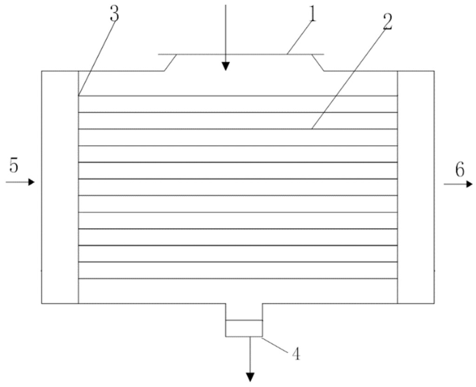
2. Model of the Marine Condenser
2.1. Heat Transfer Calculation in Condenser
2.1.1. Total HTR and Heat Balance Equation
2.1.2. Total HTC
2.1.3. Total EGR
2.2. Calculations of Pressure Drop (PD) and Required TPP
3. Constructal Design of the Marine Condenser
3.1. Constructal Design with Single Objective Optimization
3.2. Constructal Design with Multi-Objective Optimization
4. Conclusions
- (1)
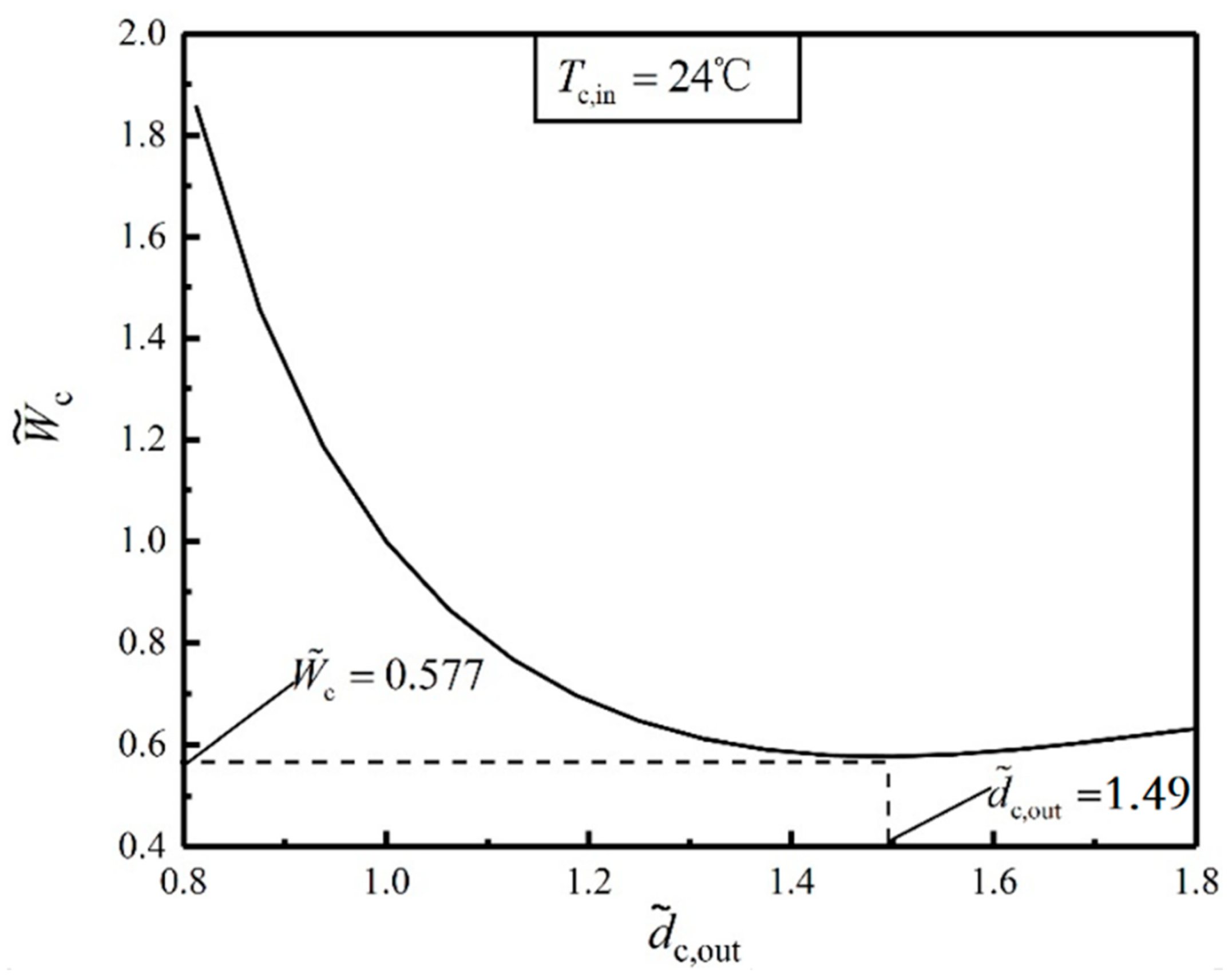
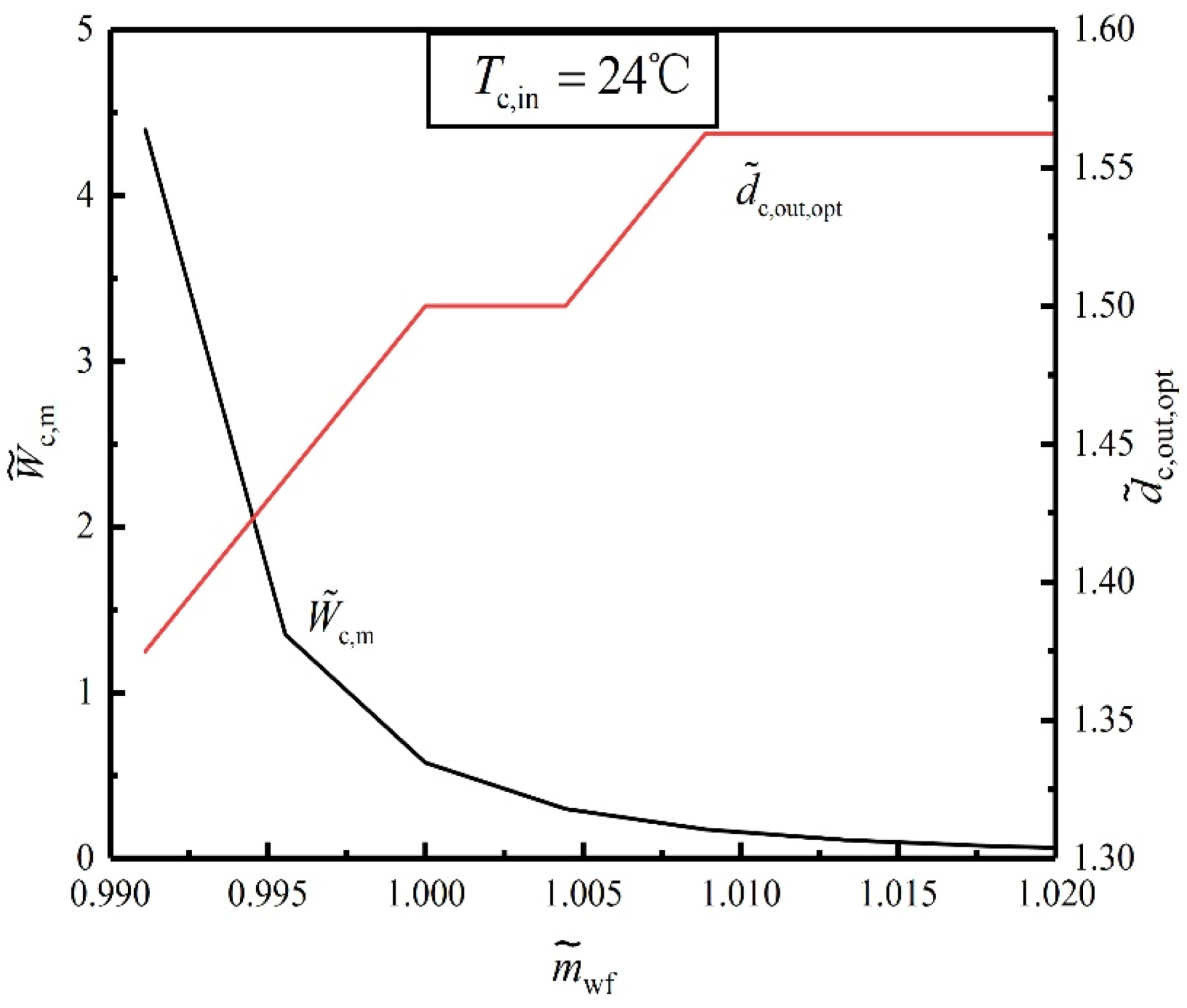
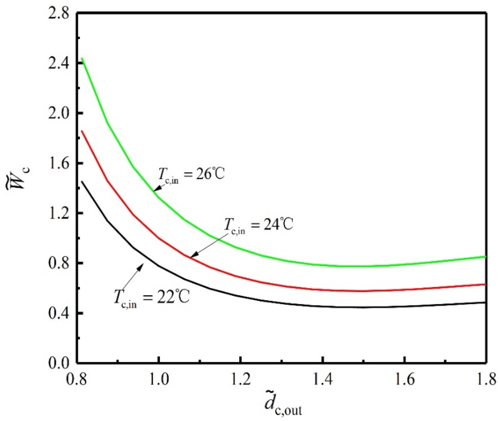
- There is an optimal dimensionless tube diameter leading to the minimum TPP required by the condenser. Compared with , the TPP of the condenser is reduced by 42.3% after constructal optimization, which greatly improves the fluid flow performance and reduces the operation cost of the condenser. As the steam MFR and HTA increase and the total HTR decreases, the minimum TPP required by the condenser decreases.
- (2)
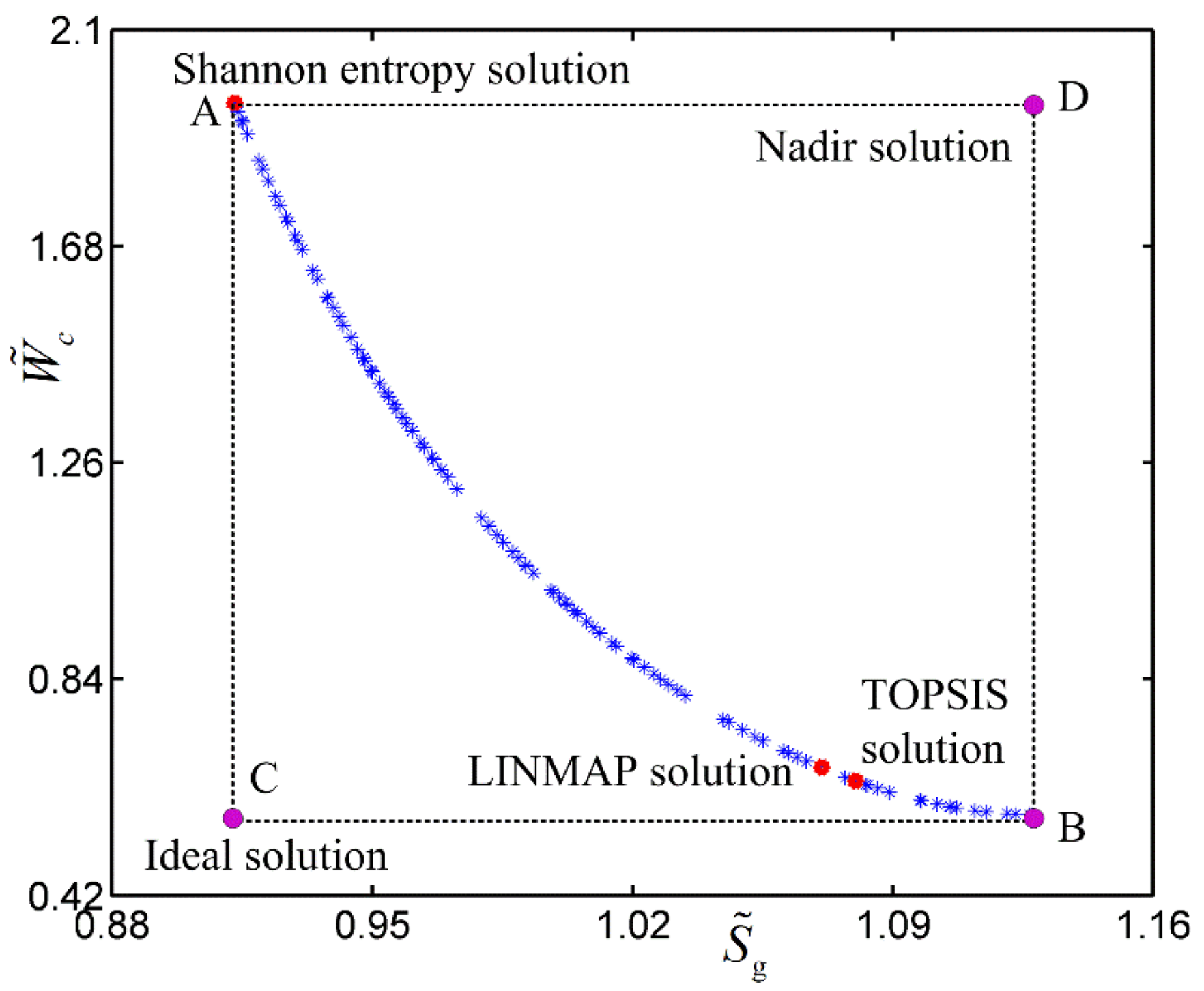
- The Pareto optimal set of the and gained by multi-objective optimization is the compromise between the EGR and TPP under different design requirements. The EGRs (or TPPs) of the condenser gained by the three decision methods are not smaller than that gained by EGR (or TPP) minimization at point A (or point B). The deviation index of the TOPSIS decision method is the smallest one. Therefore, the optimal construct gained by the TOPSIS decision method is recommended in the optimal design of the condenser.
Author Contributions
Funding
Institutional Review Board Statement
Informed Consent Statement
Data Availability Statement
Acknowledgments
Conflicts of Interest
Nomenclature
| Heat transfer area (m2) | ||||
| Diameter correction factor | ||||
| Specific heat capacity (KJ/(kg·K)) | ||||
| Diameter (m) | ||||
| Gravity acceleration (m/s2) | ||||
| Heat transfer coefficient (W/(m2·k)) | ||||
| Tube length (m) | ||||
| Mass flow rate (kg/s) | ||||
| Path number | ||||
| Tube number | ||||
| Prandtl number | ||||
| Pressure (Pa) | ||||
| Heat transfer rate (W) | ||||
| Reynolds number | ||||
| Latent heat (KJ/kg) | ||||
| Entropy generation rate (W) | ||||
| Temperature (K) | ||||
| Velocity (m/s) | ||||
| Specific volume (m3/kg) | ||||
| Pumping power (W) | ||||
| Greek letters | ||||
| Convective heat transfer coefficient (W/(m2·K)) | ||||
| Pump efficiency | ||||
| Thermal conductivity of the tube (W/(m·K)) | ||||
| Liquid film thermal conductivity (W/(m·K)) | ||||
| Kinematic viscosity (m2/s) | ||||
| Liquid film density (kg/m3) | ||||
| Subscripts | ||||
| c | Cooling water | |||
| in | Inlet | |||
| int | Initial | |||
| LH | Latent heat | |||
| m | Minimum | |||
| opt | Optimal | |||
| out | Outlet | |||
| p | Pump | |||
| s | Steam | |||
| wf | Working fluid | |||
| Superscripts | ||||
| Non-dimensionalized | ||||
Abbreviations
| CT | Condensation temperature |
| CW | Cooling water |
| CWIT | Cooling water inlet temperature |
| EGR | Entropy generation rate |
| HE | Heat exchanger |
| HL | Heat load |
| HTA | Heat transfer area |
| HTC | Heat transfer coefficient |
| HTR | Heat transfer rate |
| HTT | Heat transfer tube |
| MFR | Mass flow rate |
| MTD | Mean temperature difference |
| OD | Outer diameter |
| PD | Pressure drop |
| STHE | Shell-and-tube heat exchanger |
| TC | Thermal conductivity |
| TPP | Total pumping power |
References
- Silaipillayarputhur, K.; Khurshid, H. The design of shell and tube heat exchangers—A review. Int. J. Mech. Prod. Eng. Res. Dev. 2019, 9, 87–102. [Google Scholar]
- Kumar, S.; Singh, D. A Review on design and optimization of shell and tube heat exchanger by varying parameters. Smart Moves J. Ijosci. 2021, 6. Available online: https://ijoscience.com/ojsscience/index.php/ojsscience/article/view/298 (accessed on 1 September 2021). [CrossRef]
- Johnson, C.M.; Vanderplaats, G.N.; Marto, P.J. Marine condenser design using numerical optimization. J. Mech. Design 1980, 102, 469–475. [Google Scholar] [CrossRef]
- Patankar, S.V.; Spalding, D.B. A calculation procedure for transient and stead state behavior of shell-and-tube heat exchanger. Heat Exch. Des. Theor. Source Book 1974, 1, 155–176. [Google Scholar]
- Prithiviraj, M.; Andrews, M.J. Three dimensional numerical simulation of shell-and-tube heat exchangers. Part I: Foundation and fluid mechanics. Numer. Heat Transf. Part A Appl. 1998, 33, 799–816. [Google Scholar] [CrossRef]
- Guo, J.F.; Cheng, L.; Xu, M.T. Optimization design of shell-and-tube heat exchanger by entropy generation minimization and genetic algorithm. Appl. Therm. Eng. 2009, 29, 2954–2960. [Google Scholar] [CrossRef]
- Mirzabeygi, P.; Zhang, C. Multi-objective optimization of a steam surface condenser using the territorial particle swarm technique. J. Energy Res. Technol. 2016, 138, 052001. [Google Scholar] [CrossRef]
- Rodríguez, M.B.R.; Rodríguez, J.L.M.; Fontes, C.H.D.O. Thermo ecological optimization of shell-and-tube heat exchangers using NSGA II. Appl. Therm. Eng. 2019, 156, 91–98. [Google Scholar] [CrossRef]
- Xiao, W.; Wang, K.; Jiang, X.; Li, X.; Wu, X.; Hao, Z.; He, G. Simultaneous optimization strategies for heat exchanger network synthesis and detailed shell-and-tube heat-exchanger design involving phase changes using GA/SA. Energy 2019, 183, 1166–1177. [Google Scholar] [CrossRef]
- Yu, C.; Zhang, H.; Zeng, M.; Wang, R.; Gao, B. Numerical study on turbulent heat transfer performance of a new compound parallel flow shell and tube heat exchanger with longitudinal vortex generator. Appl. Therm. Eng. 2020, 164, 114449. [Google Scholar] [CrossRef]
- Sridhar, S.V.; Karuppasamy, R.; Sivakumar, G.D. Experimental investigation of heat transfer enhancement of shell and tube heat exchanger using SnO2-water and Ag-water nanofluids. Therm. Sci. Eng. Appl. 2020, 12, 041016. [Google Scholar] [CrossRef]
- Li, J.; Yang, Z.; Hu, S.; Yang, F.; Duan, Y. Effects of shell-and-tube heat exchanger arranged forms on the thermo-economic performance of organic Rankine cycle systems using hydrocarbons. Energy Convers. Manag. 2020, 203, 112248. [Google Scholar] [CrossRef]
- Miansari, M.; Jafarzadeh, A.; Toghraie, D. Thermal performance of a helical shell and tube heat exchanger without fin, with circular fins, and with V-shaped circular fins applying on the coil. J. Therm. Anal. Calorim. 2021, 43, 4273–4285. [Google Scholar] [CrossRef]
- Bejan, A. Street network theory of organization in nature. J. Adv. Transp. 1996, 30, 85–107. [Google Scholar] [CrossRef]
- Bejan, A. Constructal-theory network of conducting paths for cooling a heat generating volume. Int. J. Heat Mass Transf. 1997, 40, 799–816. [Google Scholar] [CrossRef]
- Bejan, A. Shape and Structure, from Engineering to Nature; Cambridge University Press: Cambridge, UK, 2000. [Google Scholar]
- Kim, S.; Lorente, S.; Bejan, A. Design with Constructal Theory: Vascularized Composites for Volumetric Cooling; ASME International: New York, NY, USA, 2008. [Google Scholar]
- Lorenzini, G.; Moretti, S.; Conti, A. Fin Shape Thermal Optimization Using Bejan's Constructal Theory; Morgan & Claypool Publishers: San Francisco, CA, USA, 2011. [Google Scholar]
- Chen, L.G. Progress in study on constructal theory and its applications. Sci. China Tech. Sci. 2012, 42, 505–524. [Google Scholar] [CrossRef]
- Chen, L.G.; Feng, H.J. Multi-Objective Constructal Optimization for Flow and Heat and Mass Transfer Processes; Science Press: Beijing, China, 2017. [Google Scholar]
- Bejan, A. Constructal law, twenty years after. Proc. Rom. Acad. Ser. A Math. Phys. Tech. Sci. Inform. Sci. 2018, 18, 309–311. [Google Scholar]
- Chen, L.G.; Feng, H.J.; Xie, Z.H.; Sun, F.R. Progress of constructal theory in China over the past decade. Int. J. Heat Mass Transf. 2019, 130, 393–419. [Google Scholar] [CrossRef]
- Lorente, S.; Bejan, A. Current trends in constructal law and evolutionary design. Heat Transf.-Asian Res. 2019, 48, 357–389. [Google Scholar] [CrossRef]
- Bejan, A. Freedom and Evolution: Hierarchy in Nature; Springer Science and Business Media LLC: Berlin, Germany, 2020. [Google Scholar]
- Chen, L.G.; Yang, A.B.; Feng, H.J.; Ge, Y.L.; Xia, S.J. Constructal designs for eight types of heat sinks. Sci. China Technol. Sci. 2020, 63, 1–33. [Google Scholar] [CrossRef]
- Wu, Z.X.; Feng, H.J.; Chen, L.G.; Ge, Y.L. Performance optimization of a condenser in ocean thermal energy conversion (OTEC) system based on constructal theory and multi-objective genetic algorithm. Entropy 2020, 22, 641. [Google Scholar] [CrossRef]
- Chen, L.G.; Wu, W.J.; Feng, H.J. Constructal Design for Heat Conduction; Book Publisher International: London, UK, 2021. [Google Scholar]
- Bejan, A.; Almahmoud, H.; Gucluer, S. Evolutionary design of composite structures for thermal conductance and strength. Int. Comm. Heat Mass Transf. 2021, 125, 105293. [Google Scholar] [CrossRef]
- Kuddusi, L.; Denton, J.C. Analytical solution for heat conduction problem in composite slab and its implementation in constructal solution for cooling of electronics. Energy Convers. Manag. 2007, 48, 1089–1105. [Google Scholar] [CrossRef]
- Marck, G.; Harion, J.L.; Nemer, M.; Russeil, S.; Bougeard, D. A new perspective of constructal networks cooling a finite-size volume generating heat. Energy Convers. Manag. 2011, 52, 1033–1046. [Google Scholar] [CrossRef]
- Tescari, S.; Mazet, N.; Neveu, P. Constructal theory through thermodynamics of irreversible processes framework. Energy Convers. Manag. 2011, 52, 3176–3188. [Google Scholar] [CrossRef]
- Zhang, F.Y.; Feng, H.J.; Chen, L.G.; You, J.; Xie, Z.J. Constructal design of an arrow-shaped high thermal conductivity channel in a square heat generation body. Entropy 2020, 22, 475. [Google Scholar] [CrossRef] [PubMed]
- Li, Y.L.; Feng, M.L. Optimal design of conductive natural branched pathways for cooling a heat-generating volume. Heat Transf. 2021, 50, 2571–2591. [Google Scholar] [CrossRef]
- Hajmohammadi, M.R.; Poozesh, S.; Campo, A.; Nourazar, S.S. Valuable reconsideration in the constructal design of cavities. Energy Convers. Manag. 2013, 66, 33–40. [Google Scholar] [CrossRef]
- Gonzales, G.V.; Lorenzini, G.; Isoldi, L.A.; Rocha, L.A.O.; dos Santos, E.D.; Silva Neto, A.J. Constructal design and simulated annealing applied to the geometric optimization of an isothermal double T-shaped cavity. Int. J. Heat Mass Transf. 2021, 174, 121268. [Google Scholar] [CrossRef]
- Lu, Z.H.; Zhang, K.; Liu, J.X.; Li, F. Effect of branching level on the performance of constructal theory based Y-shaped liquid cooling heat sink. Appl. Therm. Eng. 2020, 168, 114824. [Google Scholar] [CrossRef]
- Hazarika, S.A.; Deshmukhya, T.; Bhanja, D.; Nath, S. A novel optimum constructal fork-shaped fin array design for simultaneous heat and mass transfer application in a space-constrained situation. Int. J. Therm. Sci. 2020, 150, 106225. [Google Scholar] [CrossRef]
- Wei, S.H.; Feng, H.J.; Chen, L.G.; Ge, Y.L. Constructal equivalent thermal resistance minimization for Tau-shaped fin. Entropy 2020, 22, 1206. [Google Scholar] [CrossRef] [PubMed]
- Chen, C.; You, J.; Feng, H.J.; Chen, L.G. A multi-objective study on the constructal design of non-uniform heat generating disc cooled by radial- and dendritic-pattern cooling channels. Sci. China Technol. Sci. 2021, 64, 729–744. [Google Scholar] [CrossRef]
- Hajmohammadi, M.R.; Salimpour, M.R.; Saber, M.; Campo, A. Detailed analysis for the cooling performance enhancement of a heat source under a thick plate. Energy Convers. Manag. 2013, 76, 691–700. [Google Scholar] [CrossRef]
- Birinci, S.; Saglam, M.; Sarper, B.; Aydin, O. Constructal design of heat sources with different heat generation rates for the hot spot mitigation. Int. J. Heat Mass Transf. 2020, 163, 120472. [Google Scholar] [CrossRef]
- Neveu, P.; Tescari, S.; Aussel, D.; Mazet, N. Combined constructal and exergy optimization of thermochemical reactors for high temperature heat storage. Energy Convers. Manag. 2013, 71, 186–198. [Google Scholar] [CrossRef]
- Joshi, V.; Rathod, M.K. Constructal enhancement of thermal transport in latent heat storage systems assisted with fins. Int. J. Therm. Sci. 2019, 145, 105984. [Google Scholar] [CrossRef]
- Wu, Z.X.; Feng, H.J.; Chen, L.G.; Tang, W.; Shi, J.Z.; Ge, Y.L. Constructal thermodynamic optimization for ocean thermal energy conversion system with dual-pressure organic Rankine cycle. Energy Convers. Manag. 2020, 210, 112727. [Google Scholar] [CrossRef]
- Feng, H.J.; Wu, Z.X.; Chen, L.G.; Ge, Y.L. Constructal thermodynamic optimization for dual-pressure organic Rankine cycle in waste heat utilization system. Energy Convers. Manag. 2021, 227, 113585. [Google Scholar] [CrossRef]
- Mosa, M.; Malley-Ernewein, A. Constructal design applications in buildings: Radiant cooling panels and thermochemical energy storage. Heat Transf. 2020, 49, 3981–3996. [Google Scholar] [CrossRef]
- Rodrigues, G.C.; Lorenzini, G.; Victoria, L.C.; Vaz, I.S.; Rocha, L.A.O.; dos Santos, E.D.; Rodrigues, M.K.; da S D Estrada, E.; Isoldi, L.A. Constructal design applied to the geometric evaluation of a T-shaped earth-air heat exchanger. Int. J. Sustain. Dev. Plan. 2021, 16, 207–217. [Google Scholar] [CrossRef]
- Pinto, V.T.; Cunha, M.L.; Martins, K.L.; Rocha, L.A.O.; de Vasconcellos Real, M.; dos Santos, E.D.; Isoldi, L.A. Geometric evaluation of steel plates subjected to uniform transverse load with rectangular or trapezoidal stiffeners by means constructal design method. Int. J. Hydromechatron. 2020, 3, 190–198. [Google Scholar] [CrossRef]
- da Silveira, T.; Pinto, V.T.; Neufeld, J.P.S.; Pavlovic, A. Applicability evidence of constructal design in structural engineering: Case study of biaxial elasto-plastic buckling of square steel plates with elliptical cutout. J. Appl. Comput. Mech. 2021, 7, 922–934. [Google Scholar]
- Cetkin, E. The effect of cooling on mechanical and thermal stresses in vascular structures. J. Therm. Eng. 2018, 4, 1855–1866. [Google Scholar] [CrossRef]
- Dadsetani, R.; Sheikhzade, G.A.; Goodarzi, M.; Zeeshan, A. Thermal and mechanical design of tangential hybrid microchannel and high-conductivity inserts for cooling of disk-shaped electronic components. J. Therm. Anal. Calorim. 2021, 143, 2125–2133. [Google Scholar] [CrossRef]
- Vargas, J.V.C.; Bejan, A. Thermodynamic optimization of finned crossflow heat exchangers for aircraft environmental control systems. Int. J. Heat Fluid Flow 2001, 22, 657–665. [Google Scholar] [CrossRef]
- Bejan, A. Dendritic constructal heat exchanger with small-scale crossflows and larger-scales counterflows. Int. J. Heat Mass Transf. 2002, 45, 4607–4620. [Google Scholar] [CrossRef]
- Silva, D.A.K.; Lorente, S.; Bejan, A. Constructal multi-scale tree-shaped heat exchanger. J. Appl. Phys. 2004, 96, 1709–1718. [Google Scholar] [CrossRef]
- Silva, D.A.K.; Bejan, A. Dendritic counterflow heat exchanger experiments. Int. J. Therm. Sci. 2006, 45, 860–869. [Google Scholar] [CrossRef]
- Zimparov, V.D.; Silva, D.A.K.; Bejan, A. Constructal tree-shaped parallel flow heat exchangers. Int. J. Heat Mass Transf. 2006, 49, 4558–4566. [Google Scholar] [CrossRef]
- Azad, A.V.; Amidpour, M. Economic optimization of shell-and-tube heat exchanger based on constructal theory. Energy 2011, 36, 1087–1096. [Google Scholar] [CrossRef]
- Yang, J.; Oh, S.R.; Liu, W. Optimization of shell-and-tube heat exchangers using a general design approach motivated by constructal theory. Int. J. Heat Mass Transf. 2014, 77, 1144–1154. [Google Scholar] [CrossRef]
- Yang, J.; Fan, A.W.; Liu, W.; Jacobi, A.M. Optimization of shell-and-tube heat exchangers conforming to TEMA standards with designs motivated by constructal theory. Energy Convers. Manag. 2014, 78, 468–476. [Google Scholar] [CrossRef]
- Mirzaei, M.; Hajabdollahi, H.; Fadakar, H. Multi-objective optimization of shell-and-tube heat exchanger by constructal theory. Appl. Therm. Eng. 2017, 125, 9–19. [Google Scholar] [CrossRef]
- Manjunath, K.; Kaushik, S.C. Second law analysis of unbalanced constructal heat exchanger. Int. J. Green Energy 2014, 11, 173–192. [Google Scholar] [CrossRef]
- Bejan, A.; Lorente, S.; Martins, L.; Meyer, J.P. The constructal size of a heat exchanger. J. Appl. Phys. 2017, 122, 064902. [Google Scholar] [CrossRef]
- Hajabdollahi, H. Multi-objective optimization of plate fin heat exchanger using constructal theory. Int. Commun. Heat Mass Transf. 2019, 108, 104283. [Google Scholar] [CrossRef]
- Ariyo, D.O.; Bello-Ochende, T. Constructal design of subcooled microchannel heat exchangers. Int. J. Heat Mass Transf. 2020, 146, 118835. [Google Scholar] [CrossRef]
- Martins, L.S.; Ordonez, J.C.; Vargas, J.V.C.; Parise, J.A.R. Thermodynamic optimization of a regenerator heat exchanger. Appl. Therm. Eng. 2012, 45, 42–51. [Google Scholar] [CrossRef]
- Bejan, A.; Lorente, S.; Kang, D.H. Constructal design of regenerators. Int. J. Energy Res. 2013, 37, 1509–1518. [Google Scholar] [CrossRef]
- Bejan, A.; Lorente, S.; Anderson, R. Constructal underground designs for ground-coupled heat pumps. Trans. ASME J. Sol. Energy Eng. 2014, 136, 011019. [Google Scholar] [CrossRef]
- Rodrigues, M.K.; Silva, D.B.R.; Vaz, J.; Rocha, L.A.O.; Santos, D.E.D.; Isoldi, L.A. Numerical investigation about the improvement of the thermal potential of an earth-air heat exchanger (EAHE) employing the constructal design method. Renew. Energy 2015, 80, 538–551. [Google Scholar] [CrossRef]
- Cai, C.G.; Feng, H.J.; Chen, L.G.; Wu, Z.X.; Xie, Z.J. Constructal design of a shell-and-tube evaporator with ammonia-water working fluid. Int. J. Heat Mass Transf. 2019, 135, 541–547. [Google Scholar] [CrossRef]
- Wu, Z.X.; Feng, H.J.; Chen, L.G.; Xie, Z.J.; Cai, C.G. Pumping power minimization of an evaporator in ocean thermal energy conversion system based on constructal theory. Energy 2019, 181, 974–984. [Google Scholar] [CrossRef]
- Xie, Z.J.; Feng, H.J.; Chen, L.G.; Wu, Z.X. Constructal design for supercharged boiler evaporator. Int. J. Heat Mass Transf. 2019, 138, 571–579. [Google Scholar] [CrossRef]
- Feng, H.J.; Xie, Z.J.; Chen, L.G.; Wu, Z.X.; Xia, S.J. Constructal design for supercharged boiler superheater. Energy 2020, 191, 116484. [Google Scholar] [CrossRef]
- Tang, W.; Feng, H.J.; Chen, L.G.; Xie, Z.J.; Shi, J.Z. Constructal design for a boiler economizer. Energy 2021, 223, 120013. [Google Scholar] [CrossRef]
- Gulotta, T.M.; Guarino, F.; Cellura, M.; Lorenzini, G. Constructal law optimization of a boiler. Int. J. Heat Technol. 2017, 35, 297–305. [Google Scholar] [CrossRef]
- Gulotta, T.M.; Guarino, F.; Cellura, M.; Lorenzini, G. A constructal law optimization of a boiler inspired by life cycle thinking. Therm. Sci. Eng. Prog. 2018, 6, 380–387. [Google Scholar] [CrossRef]
- Kim, Y.S.; Lorente, S.; Bejan, A. Constructal steam generator architecture. Int. J. Heat Mass Transf. 2009, 52, 2362–2369. [Google Scholar] [CrossRef]
- Norouzi, E.; Amidpour, M. Optimal thermodynamic and economic volume of a heat recovery steam generator by constructal design. Int. Commun. Heat Mass Transf. 2012, 39, 1286–1292. [Google Scholar] [CrossRef]
- Mehrgoo, M.; Amidpour, M. Constructal design and optimization of a dual pressure heat recovery steam generator. Energy 2017, 124, 87–99. [Google Scholar] [CrossRef]
- Norouzi, E.; Amidpour, M.; Rezakazemi, M. Heat recovery steam generator: Constructal thermoeconomic optimization. Appl. Therm. Eng. 2019, 148, 747–753. [Google Scholar] [CrossRef]
- Bejan, A.; Lee, J.; Lorente, S.; Kim, Y. The evolutionary design of condensers. J. Appl. Phys. 2015, 117, 125101. [Google Scholar] [CrossRef]
- Li, B.T.; Xu, J.H.; Y, N.; Hong, J. Optimization design of grooved condenser wick structures in a vapor chamber for electronic cooling applications. Struct. Multidiscipl. Optim. 2019, 61, 1–19. [Google Scholar] [CrossRef]
- Xu, W. Numerical and Experimental Studies of Vapor-Liquid Two-Phase Flow and Heat Transfer in Marine Condenser. Ph.D. Thesis, Harbin Engineering University, Harbin, China, 2015. (In Chinese). [Google Scholar]
- Yang, S.M.; Tao, W.Q. Heat Transfer; Higher Education Press: Beijing, China, 2006. (In Chinese) [Google Scholar]
- Li, Y.Q.; Liao, S.M.; Liu, G. Thermo-economic multi-objective optimization for a solar-dish Brayton system using NSGA-II and decision making. Int. J. Electr. Power Energy Syst. 2015, 64, 167–175. [Google Scholar] [CrossRef]
- Ghorani, M.M.; Haghighi, M.H.S.; Riasi, A. Entropy generation minimization of a pump running in reverse mode based on surrogate models and NSGA-II. Int. Commun. Heat Mass Transf. 2020, 118, 104898. [Google Scholar] [CrossRef]
- Ghazvini, M.; Pourkiaei, S.M.; Pourfayaz, F. Thermo-economic assessment and optimization of actual heat engine performance by implemention of NSGA II. Renew. Energy Res. Appl. 2020, 1, 235–245. [Google Scholar]
- Wang, L.B.; Bu, X.B.; Li, H.S. Multi-objective optimization and off-design evaluation of organic rankine cycle (ORC) for low-grade waste heat recovery. Energy 2020, 203, 117809. [Google Scholar] [CrossRef]
- Lee, U.; Park, S.; Lee, I. Robust design optimization (RDO) of thermoelectric generator system using non-dominated sorting genetic algorithm II (NSGA-II). Energy 2020, 196, 117090. [Google Scholar] [CrossRef]
- Li, Y.Y.; Wang, S.Q.; Duan, X.B.; Liu, S.J.; Liu, J.P.; Hu, S. Multi-objective energy management for Atkinson cycle engine and series hybrid electric vehicle based on evolutionary NSGA-II algorithm using digital twins. Energy Convers. Manag. 2021, 230, 113788. [Google Scholar] [CrossRef]
- Yusuf, A.; Bayhan, N.; Tiryaki, H.; Hamawandi, B.; Toprak, M.S.; Ballikaya, S. Multi-objective optimization of concentrated photovoltaic-thermoelectric hybrid system via non-dominated sorting genetic algorithm (NSGA II). Energy Convers. Manag. 2021, 236, 114065. [Google Scholar] [CrossRef]
- Ahmadi, M.H.; Ahmadi, M.A.; Shafaei, A.; Ashouri, M.; Toghyani, S. Thermodynamic analysis and optimization of the Atkinson engine by using NSGA-II. Int. J. Low-Carbon Technol. 2016, 11, 317–324. [Google Scholar] [CrossRef] [Green Version]
- Xu, Z.; Guo, Y.Q.; Mao, H.T.; Yang, F.Q. Configuration optimization and performance comparison of STHX-DDB and STHX-SB by a multi-objective genetic algorithm. Energies 2019, 12, 1794. [Google Scholar] [CrossRef] [Green Version]
- Tang, C.Q.; Feng, H.J.; Chen, L.G.; Wang, W.H. Power density analysis and multi-objective optimization for a modified endoreversible simple closed Brayton cycle with one isothermal heat process. Energy Rep. 2020, 6, 1648–1657. [Google Scholar] [CrossRef]
- Meng, J.H.; Wu, H.C.; Wang, T.H. Optimization of two-stage combined thermoelectric devices by a three-dimensional multi-physics model and multi-objective genetic algorithm. Energies 2019, 12, 2832. [Google Scholar] [CrossRef] [Green Version]
- Abedinnezhad, S.; Ahmadi, M.H.; Pourkiaei, S.M.; Pourfayaz, F.; Mosavi, A.; Feidt, M.; Shamshirband, S. Thermodynamic assessment and multi-objective optimization of performance of irreversible Dual-Miller cycle. Energies 2019, 12, 4000. [Google Scholar] [CrossRef] [Green Version]
- Sun, M.; Xia, S.J.; Chen, L.G.; Wang, C.; Tang, C.Q. Minimum entropy generation rate and maximum yield optimization of sulfuric acid decomposition process using NSGA-II. Entropy 2020, 22, 1065. [Google Scholar] [CrossRef]
- Shi, S.S.; Ge, Y.L.; Chen, L.G.; Feng, F.J. Four objective optimization of irreversible Atkinson cycle based on NSGA-II. Entropy 2020, 22, 1150. [Google Scholar] [CrossRef]
- Chen, L.G.; Tang, C.Q.; Feng, H.J.; Ge, Y.L. Power, efficiency, power density and ecological function optimizations for an irreversible modified closed variable-temperature reservoir regenerative Brayton cycle with one isothermal heating process. Energies 2020, 13, 5133. [Google Scholar] [CrossRef]
- Zhang, L.; Chen, L.G.; Xia, S.J.; Ge, Y.L.; Wang, C.; Feng, H.J. Multi-objective optimization for helium-heated reverse water gas shift reactor by using NSGA-II. Int. J. Heat Mass Transf. 2020, 148, 119025. [Google Scholar] [CrossRef]
- Jankowski, M.; Borsukiewicz, A.; Hooman, K. Development of decision-making tool and pareto set analysis for bi-objective optimization of an ORC power plant. Energies 2020, 13, 5280. [Google Scholar] [CrossRef]
- Tang, C.Q.; Chen, L.G.; Feng, H.J.; Ge, Y.L. Four-objective optimizations for an improved irreversible closed modified simple Brayton cycle. Entropy 2021, 23, 282. [Google Scholar] [CrossRef] [PubMed]
- Yang, J.Y.; Gao, L.; Ye, Z.H.; Hwang, Y.H.; Chen, J.P. Binary-objective optimization of latest low-GWP alternatives to R245fa for organic Rankine cycle application. Energy 2021, 216, 119336. [Google Scholar] [CrossRef]
- Shi, S.S.; Chen, L.G.; Ge, Y.L.; Feng, F.J. Performance optimizations with single-, bi-, tri- and quadru-objective for irreversible Diesel cycle. Entropy 2021, 23, 826. [Google Scholar] [CrossRef] [PubMed]
- Shi, S.S.; Chen, L.G.; Ge, Y.L.; Feng, F.J. Performance optimizations with single-, bi-, tri- and quadru-objective for irreversible Atkinson cycle with nonlinear variation of working fluid's specific heat. Energies 2021, 14, 4175. [Google Scholar] [CrossRef]
- Zhang, Z.M.; Feng, H.J.; Chen, L.G.; Ge, Y.L. Multi-objective constructal design for compound heat dissipation channels in a three-dimensional trapezoidal heat generation body. Int. Commun. Heat Mass Transf. 2021, 127, 105584. [Google Scholar] [CrossRef]
- Gong, Q.R.; Ge, Y.L.; Chen, L.G.; Shi, S.S.; Feng, H.J. Performance analyses and four-objective optimizations of an irreversible rectangular cycle. Entropy 2021, 23. in press. [Google Scholar]


| Optimization Methods | Optimization Results | Deviation Index | |||
|---|---|---|---|---|---|
| Multi-objective Optimizations | LINMAP | 1.22 | 1.071 | 0.668 | 0.124 |
| TOPSIS | 1.26 | 1.080 | 0.642 | 0.120 | |
| Shannon Entropy | 0.80 | 0.913 | 1.958 | 0.865 | |
| Single Objective Optimizations | 0.80 | 0.913 | 1.958 | 0.865 | |
| 1.49 | 1.128 | 0.577 | 0.134 | ||
Publisher’s Note: MDPI stays neutral with regard to jurisdictional claims in published maps and institutional affiliations. |
© 2021 by the authors. Licensee MDPI, Basel, Switzerland. This article is an open access article distributed under the terms and conditions of the Creative Commons Attribution (CC BY) license (https://creativecommons.org/licenses/by/4.0/).
Share and Cite
Feng, H.; Tang, W.; Chen, L.; Shi, J.; Wu, Z. Multi-Objective Constructal Optimization for Marine Condensers. Energies 2021, 14, 5545. https://doi.org/10.3390/en14175545
Feng H, Tang W, Chen L, Shi J, Wu Z. Multi-Objective Constructal Optimization for Marine Condensers. Energies. 2021; 14(17):5545. https://doi.org/10.3390/en14175545
Chicago/Turabian StyleFeng, Huijun, Wei Tang, Lingen Chen, Junchao Shi, and Zhixiang Wu. 2021. "Multi-Objective Constructal Optimization for Marine Condensers" Energies 14, no. 17: 5545. https://doi.org/10.3390/en14175545
APA StyleFeng, H., Tang, W., Chen, L., Shi, J., & Wu, Z. (2021). Multi-Objective Constructal Optimization for Marine Condensers. Energies, 14(17), 5545. https://doi.org/10.3390/en14175545