
Analysis and Experimental Verification of the Demagnetization Vulnerability in Various PM Synchronous Machine Configurations for an EV Application


Abstract
:1. Introduction
2. Demagnetization Principles and Baseline PM Machines
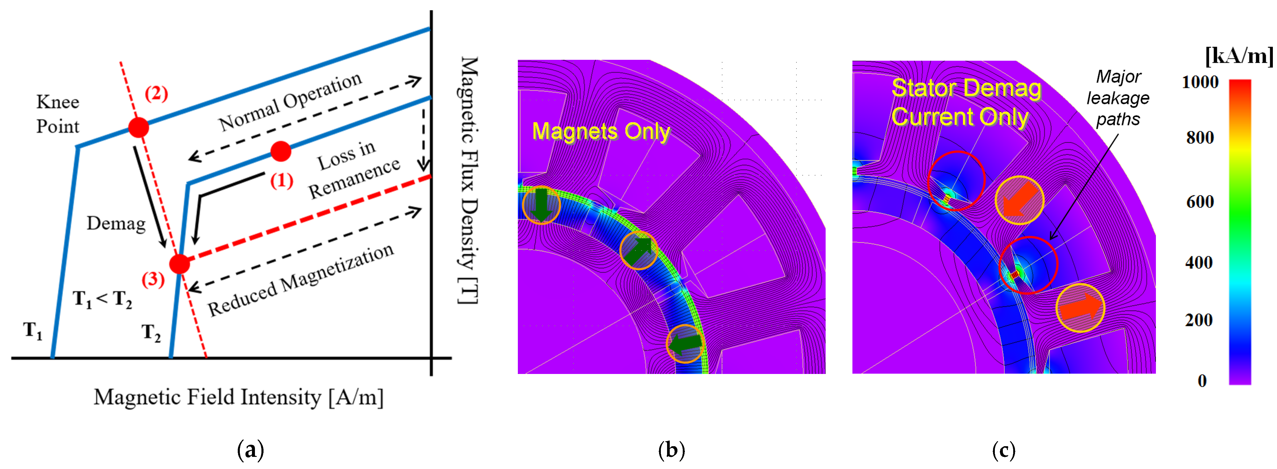
2.1. Demagnetization Principles
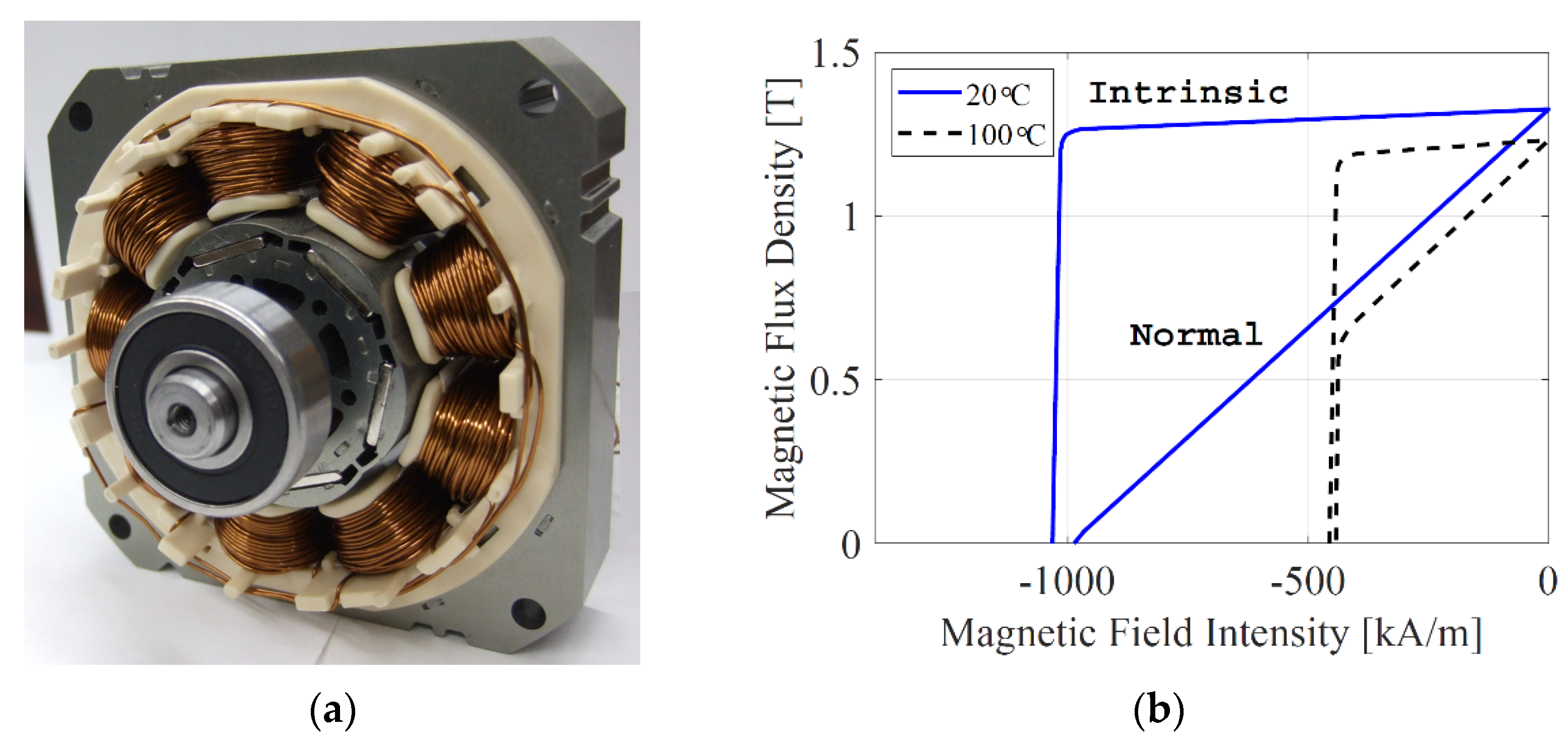
2.2. Baseline PM Machines
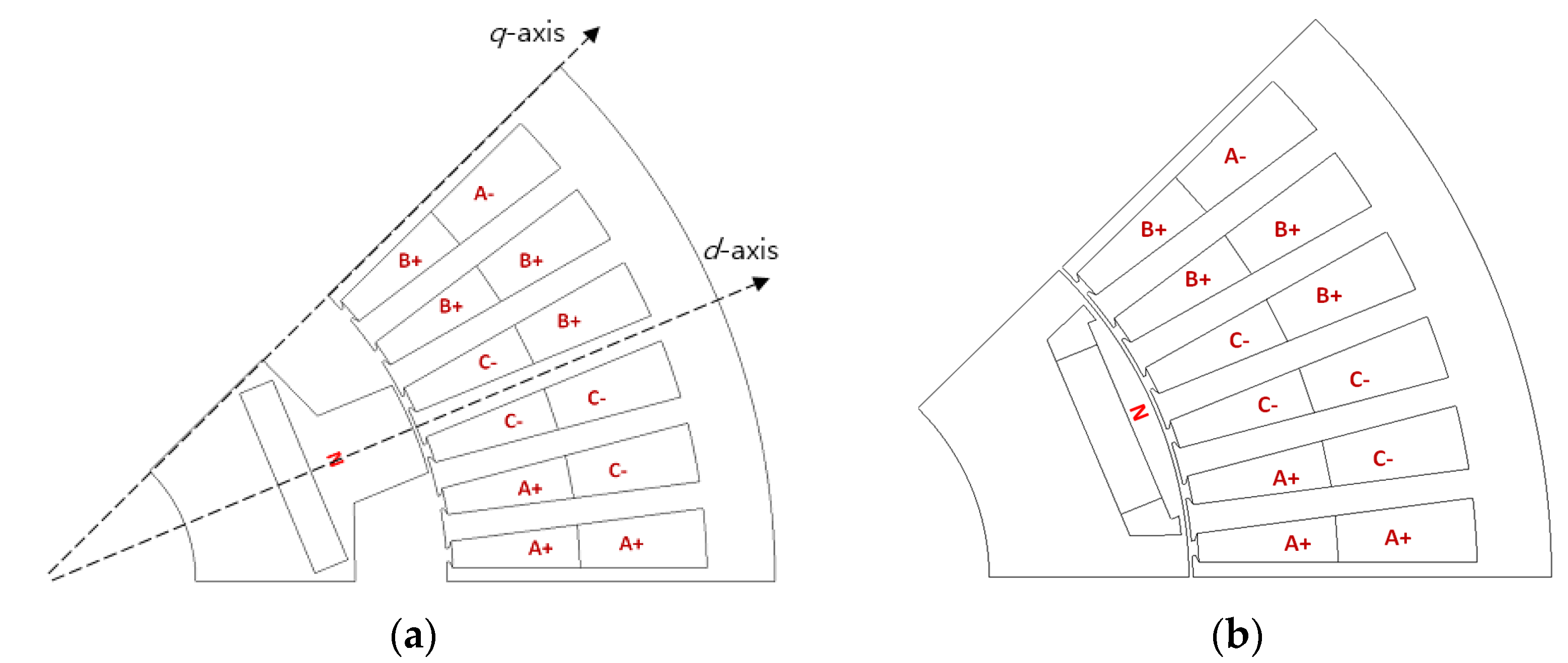
2.3. FW-IPM vs. FI-IPM
3. Simulation Results
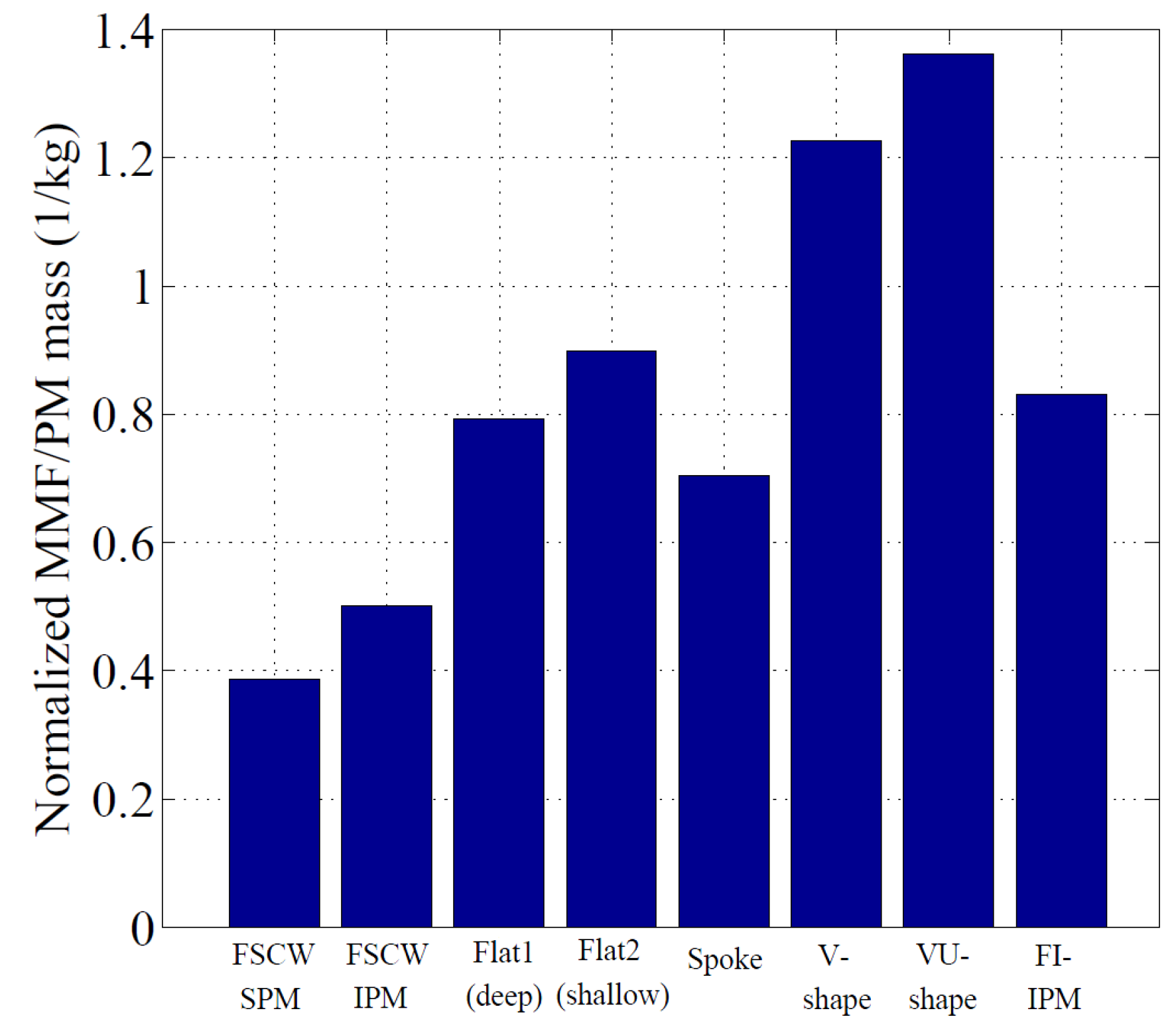
3.1. Baseline PM Machines
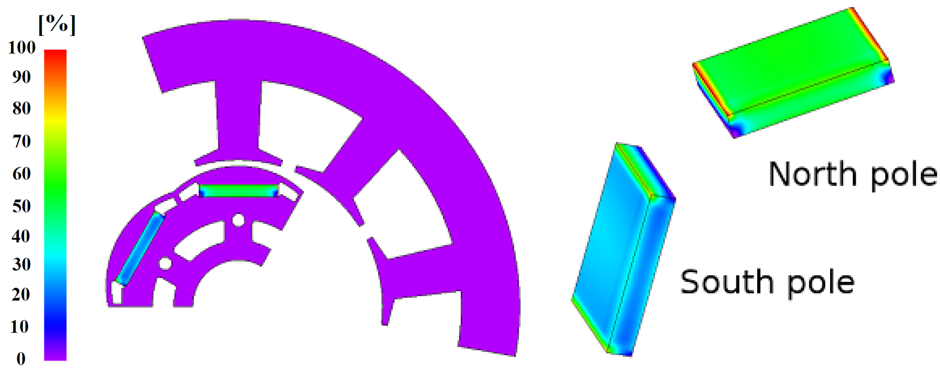
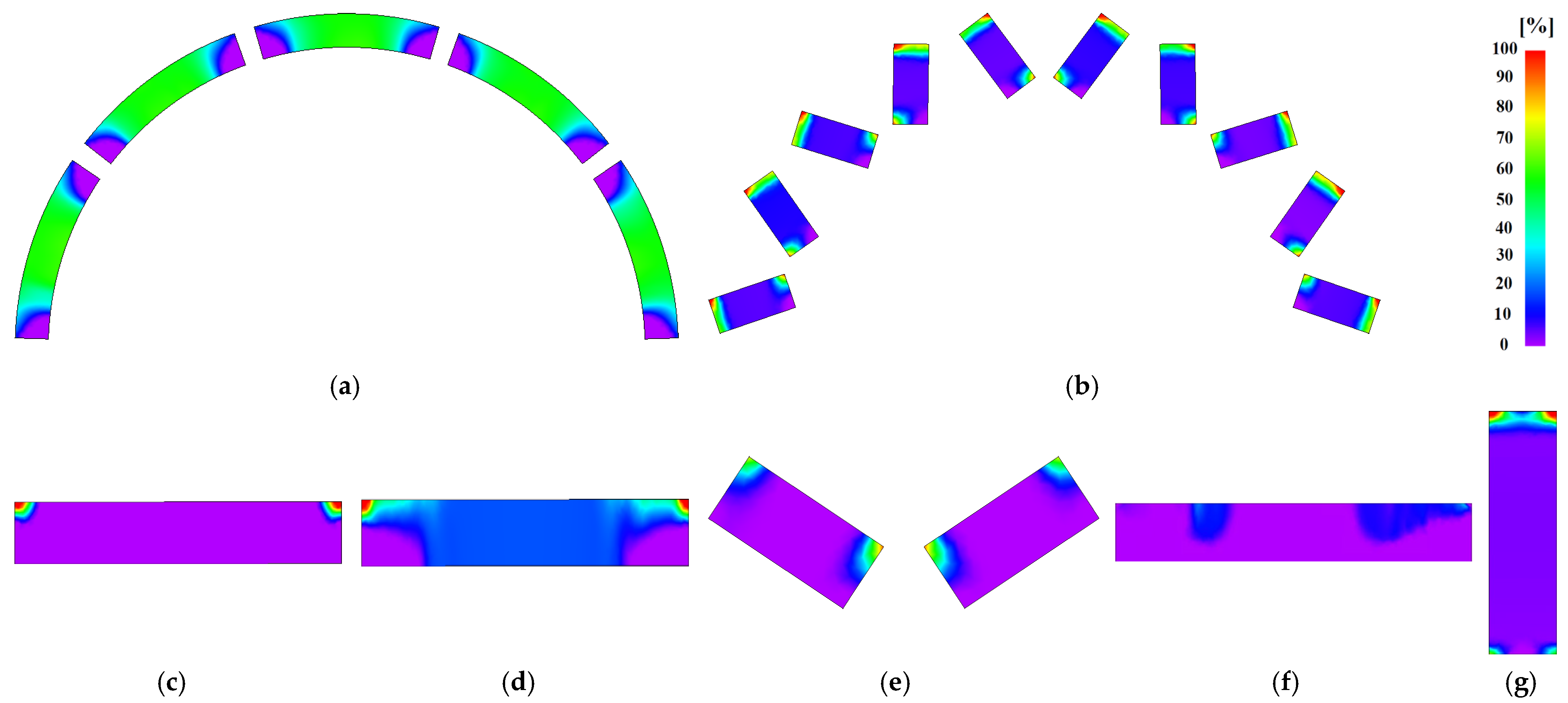
3.2. Remanence Ratio Contour Plots
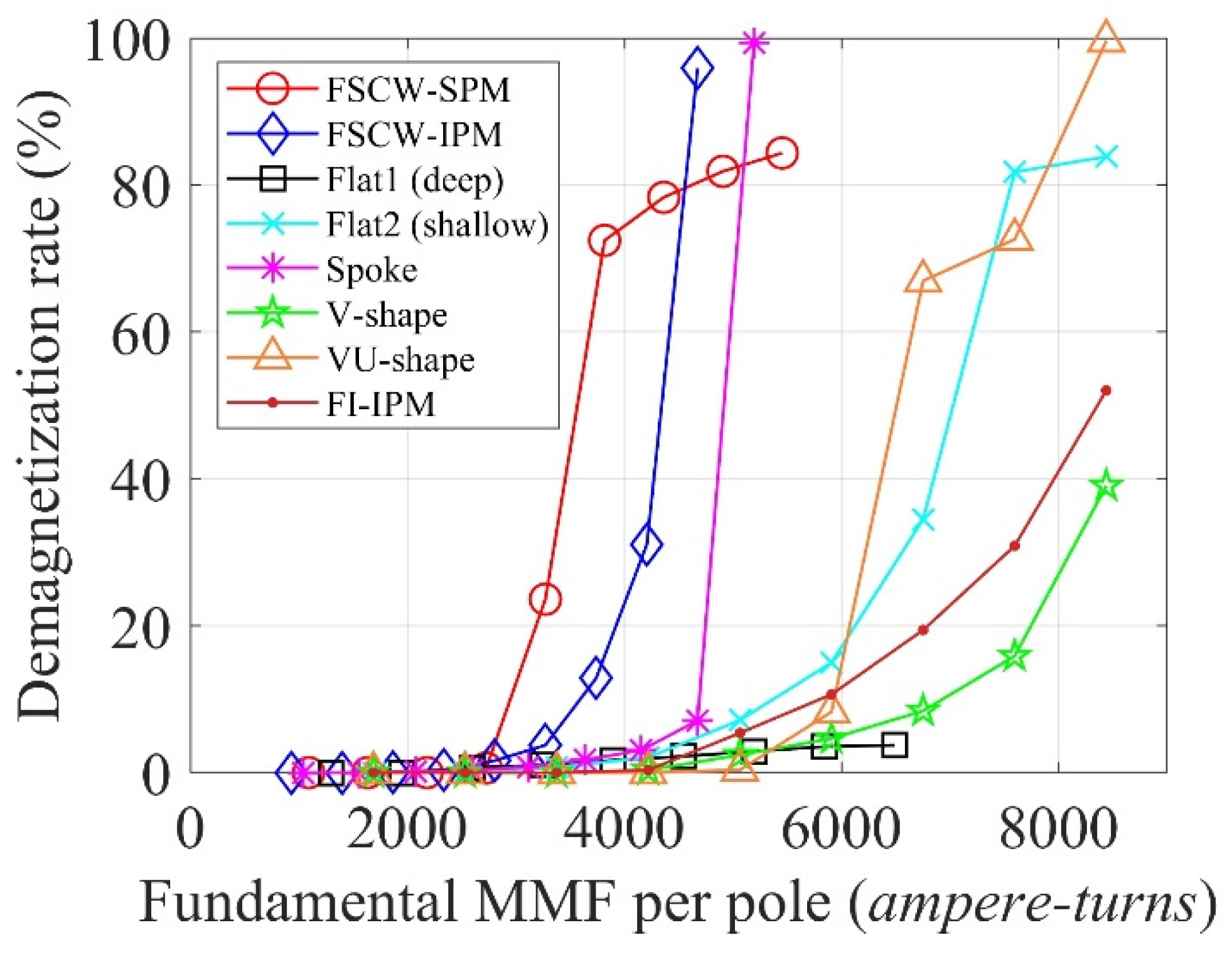
3.3. Demagnetization Index
3.4. Impact of q-Axis Current
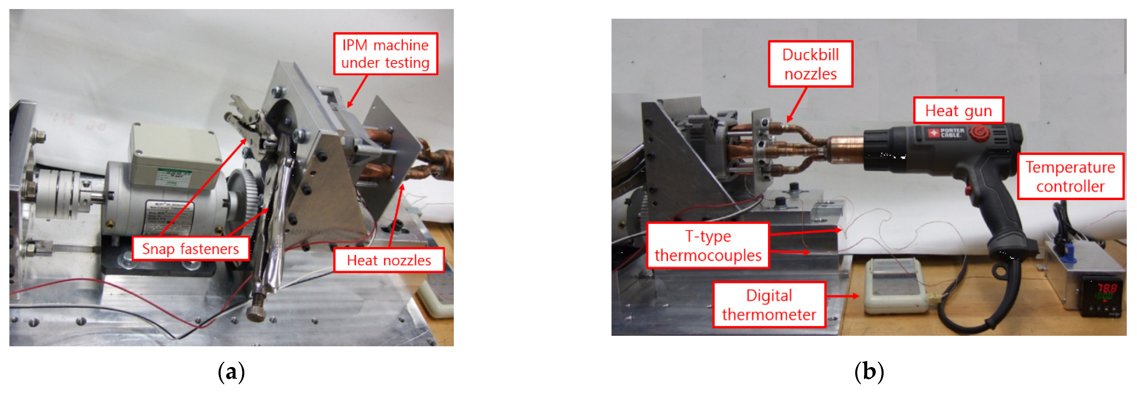
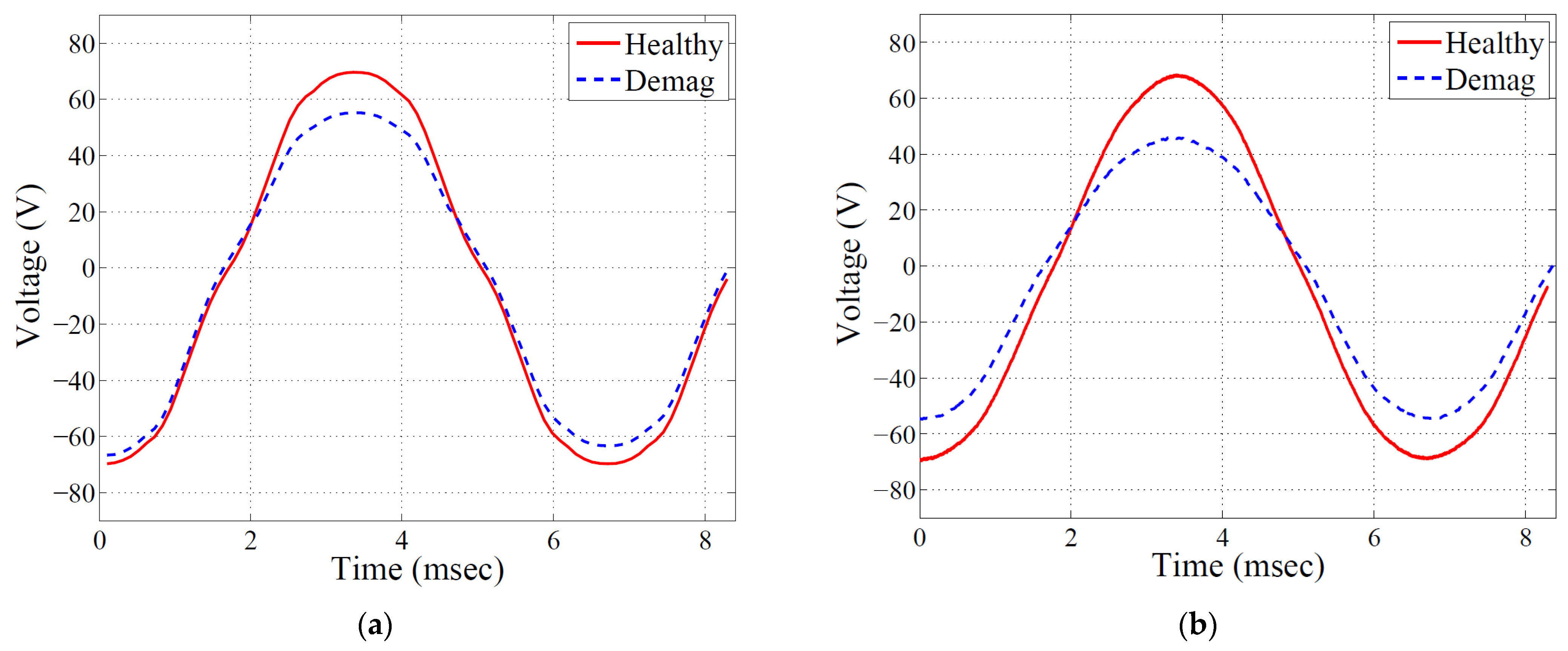
4. Experimental Verification
Tested FSCW-IPM Machine
5. Discussion
6. Conclusions
Funding
Institutional Review Board Statement
Informed Consent Statement
Acknowledgments
Conflicts of Interest
Abbreviations
| 2D | Two-dimensional |
| 3D | Three-dimensional |
| DW | Distributed windings |
| EV | Electric vehicle |
| FE | Finite element |
| FI | Flux intensifying |
| FSCW | Fractional-slot concentrated winding |
| FW | Distributed winding |
| IPM | Interior permanent magnet |
| MMF | Magnetomotive force |
| NdFeB | Neodymium–iron–boron |
| PM | Permanent magnet |
| PMSM | Permanent magnet synchronous machine |
| pu | Per unit |
| SPM | Surface permanent magnet |
References
- Ruoho, R.; Kolehmainen, J.; Ikaheimo, J.; Arkkio, A. Interdependence of Demagnetization, Loading, and Temperature Rise in a PM Synchronous Motor. IEEE Trans. Magn. 2010, 46, 949–953. [Google Scholar] [CrossRef]
- Lipo, T.A. Introduction to AC Machine Design; University of Wisconsin: Madison, WI, USA, 2007. [Google Scholar]
- Hendershot, J.R.; Miller, T.J.E. Design of Brushless Permanent Magnet Machines; Clarendon: Oxford, UK, 2010. [Google Scholar]
- Bianchi, N.; Jahns, T.M. (Eds.) Design, Analysis, and Control of Interior PM Synchronous Machines, Tutorial Course Notes. In Proceedings of the IEEE Industry Appl. Society Annual Meeting, Seattle, WA, USA, 3–7 October 2004. [Google Scholar]
- Sanada, M.; Inoue, Y.; Morimoto, S. Rotor Structure for Reducing Demagnetization of Magnet in a PMASynRM with Ferrite Permanent Magnet and its Characteristics. In Proceedings of the IEEE Energy Conversion Congress and Exposition (ECCE), Phoenix, AZ, USA, 17–22 September 2011; pp. 4189–4194. [Google Scholar]
- Vagati, A.; Boazzo, B.; Guglielmi, P.; Pellegrino, G. Design of Ferrite Assisted Synchronous Reluctance Machines Robust towards Demagne-tization. IEEE Trans. Ind. Appl. 2013, 50, 1768–1779. [Google Scholar] [CrossRef] [Green Version]
- Farooq, J.; Srairi, S.; Djerdir, A.; Miraoui, A. Use of Permeance Network Method in the Demagnetization Phenomenon Modeling in a Permanent Magnet Motor. IEEE Trans. Magn. 2006, 42, 1295–1298. [Google Scholar] [CrossRef]
- Kang, G.-H.; Hur, J.; Sung, H.-G.; Hong, J.-P. Optimal Design of Spoke Type BLDC Motor Considering Irreversible Demagnetization of Permanent Magnet. In Proceedings of the International Conference Electrical Machines and Systems (ICEMS), Beijing, China, 9–11 November 2003; Volume 1, pp. 234–237. [Google Scholar]
- Bianchi, N.; Bolognani, S.; Luisem, F. Potentials and Limits of High-Speed PM Motors. IEEE Trans. Ind. Appl. 2004, 40, 1570–1578. [Google Scholar] [CrossRef]
- Lee, B.-K.; Kang, G.-H.; Hur, J.; You, D.-W. Design of Spoke Type BLDC Motors with High Power Density for Traction Applications. In Proceedings of the IEEE Ind. Applicat. Conf. 39th IAS Annu. Meeting, Seattle, WA, USA, 3–7 October 2004; Volume 2, pp. 1068–1074. [Google Scholar]
- Hosoi, T.; Watanabe, H.; Shima, K.; Fukami, T.; Hanaoka, R.; Takata, S. Demagnetization Analysis of Additional Permanent Magnets in Salient-Pole Synchronous Machines With Damper Bars Under Sudden Short Circuits. IEEE Trans. Ind. Electron. 2012, 59, 2448–2456. [Google Scholar] [CrossRef]
- Kim, K.-C.; Kim, K.; Kim, H.J.; Lee, J. Demagnetization Analysis of Permanent Magnets According to Rotor Types of Interior Permanent Magnet Synchronous Motor. IEEE Trans. Magn. 2009, 45, 2799–2802. [Google Scholar]
- Ruoho, S.; Kolehmainen, J.; Ikaheimo, J.; Arkkio, A. Demagnetization Testing for a Mixed-Grade Dovetail Permanent-Magnet Machine. IEEE Trans. Magn. 2009, 45, 3284–3289. [Google Scholar] [CrossRef]
- McFarland, J.D.; Jahns, T.M. Investigation of the rotor demagnetization characteristics of interior PM synchronous machines during fault conditions. In Proceedings of the IEEE Energy Conversion Congress and Exposition (ECCE), Raleigh, NC, USA, 15–20 September 2012; pp. 4021–4028. [Google Scholar]
- McFarland, J.D.; Jahns, T.M. Influence of d- and q-Axis Currents on Demagnetization in PM Synchronous Machines. In Proceedings of the Energy Conversion Congress & Exposition (ECCE), Denver, CO, USA, 15–19 September 2013; pp. 4380–4387. [Google Scholar]
- Kakihara, W.; Takemoto, M.; Ogasawara, S. Rotor Structure in 50 kW Spoke-Type Interior Permanent Magnet Synchronous Motor with Ferrite Permanent Magnets for Automotive Applications. In Proceedings of the Energy Conversion Congress and Exposition (ECCE), Denver, CO, USA, 15–19 September 2013; pp. 606–613. [Google Scholar]
- Lee, S.G.; Kim, K.-S.; Lee, J.; Kim, W.H. A Novel Methodology for the Demagnetization Analysis of Surface Permanent Magnet Synchronous Motors. IEEE Trans. Magn. 2016, 52, 1–4. [Google Scholar] [CrossRef]
- Bekir, W.; Messal, O.; Benabou, A. Permanent Magnet Non-linear Demagnetization Model for FEM Simulation Environment. IEEE Trans. Magn. 2021. [Google Scholar] [CrossRef]
- Fukisaki, J.; Furuya, A.; Shitara, H.; Uehara, Y.; Kobayashi, K.; Hayashi, Y.; Ozaki, K. Demagnetization Correction Method by Using Inverse Analysis Considering Demagnetizing Field Distribution. IEEE Trans. Magn. 2020, 56, 1–4. [Google Scholar] [CrossRef]
- Kong, Y.; Lin, M.; Yin, M.; Hao, L. Rotor Structure on Reducing Demagnetization of Magnet and Torque Ripple in a PMa-SynRM with Ferrite Permanent Magnet. IEEE Trans. Magn. 2018, 54, 1–5. [Google Scholar] [CrossRef]
- Yoon, K.-Y.; Hwang, K.-Y. Optimal Design of Spoke-Type IPM Motor Allowing Irreversible Demagnetization to Minimize PM Weight. IEEE Access 2021, 9, 65721–65729. [Google Scholar] [CrossRef]
- Wang, M.; Zhu, H.; Zhou, C.; Zheng, P.; Tong, C. Analysis and Optimization of a V-shape Combined Pole Interior Permanent-Magnet Synchronous Machine with Temperature Rise and Demagnetization Considered. IEEE Access 2021, 9, 64761–64775. [Google Scholar] [CrossRef]
- Kim, K.; Lee, Y.; Hur, J.; Member, S. Transient Analysis of Irreversible Demagnetization of Permanent-Magnet Brushless DC Motor with Interturn Fault Under the Operating State. IEEE Trans. Ind. 2014, 50, 3357–3364. [Google Scholar] [CrossRef]
- le Roux, W.; Harley, R.G.; Habetler, T.G. Detecting Rotor Faults in Low Power Permanent Magnet Synchronous Machines. IEEE Trans. Power Electron. 2007, 22, 322–328. [Google Scholar] [CrossRef]
- Xiong, H.; Zhang, J.; Degner, M.W.; Rong, C.; Liang, F.; Li, W. Permanent Magnet Demagnetization Test Fixture Design and Validation. IEEE Trans. Ind. Appl. 2016, 52, 2961–2970. [Google Scholar] [CrossRef]
- Choi, G.; Jahns, T.M. Demagnetization Characteristics of Permanent Magnet Synchronous Machines. In Proceedings of the 40th Annual Conference of the IEEE Industrial Electronics Society (IECON), Dallas, TX, USA, 29 October–1 November 2014; pp. 469–475. [Google Scholar]
- Chu, W.Q.; Zhu, Z.Q. Average Torque Separation in Permanent Magnet Synchronous Machines using Frozen Permeability. IEEE Trans. Magn. 2013, 49, 1202–1210. [Google Scholar] [CrossRef]
- Limsuwan, N.; Kato, T.; Akatsu, K.; Lorenz, R.D. Design and Evaluation of a Variable-Flux Flux-Intensifying Interior Permanent-Magnet Machine. IEEE Trans. Ind. Appl. 2014, 50, 1015–1024. [Google Scholar] [CrossRef]
- Choi, G.; Jahns, T.M. Analysis and Design Recommendations to Mitigate Demagnetization Vulnerability in Surface PM Synchronous Machines. IEEE Trans. Ind. Appl. 2018, 54, 1292–1301. [Google Scholar] [CrossRef]
- Choi, G.; Zhang, Y.; Jahns, T.M. Experimental Verification of Rotor Demagnetization in a Fractional-Slot Concentrated-Winding PM Synchronous Machine Under Drive Fault Conditions. IEEE Trans. Ind. Appl. 2017, 53, 3467–3475. [Google Scholar] [CrossRef]


| Dimensions/Metrics | Design 1 | Design 2 | Design 3 | Design 4 | Design 5 | Design 6 | Design 7 |
|---|---|---|---|---|---|---|---|
| Winding type | FSCW | FSCW | ISDW | ISDW | ISDW | ISDW | ISDW |
| Rotor type | SPM | V shape | Flat 1 | Flat 2 | Spoke | V shape | VU shape |
| Slot/pole | 12/10 | 12/10 | 48/8 | 48/8 | 48/8 | 48/8 | 48/8 |
| Stator diameter [mm] | 275 | 261 | 273 | 291 | 260 | 291 | 291 |
| Rotor diameter [mm] | 160 | 160 | 160 | 160 | 160 | 160 | 160 |
| Stack length [mm] | 96 | 98 | 113 | 88 | 148 | 88 | 85 |
| Estimated volume [pu] | 1.09 | 1 | 1.26 | 1.13 | 1.50 | 1.13 | 1.09 |
| Magnet remanence [T] at 180 degC | 1.01 | 1.01 | 1.01 | 1.01 | 1.01 | 1.01 | 1.01 |
| Unsaturated saliency | ≈1 | 1.51 | 2.18 | 2.21 | 1.58 | 2.39 | 2.29 |
| Magnet mass [kg] | 2.59 | 2.23 | 2.40 | 1.71 | 2.11 | 1.55 | 1.41 |
| Parameter | FI-IPM | FW-IPM |
|---|---|---|
| Slot/pole | 48/8 | 48/8 |
| Peak power/torque at base speed | 80.5 kW/281 Nm | 80.5 kW/281 Nm |
| Peak speed | 10,000 r/min | 10,000 r/min |
| Stator/rotor diameter | 290.8 mm/160 mm | 290.8 mm/160 mm |
| Airgap length | 0.73 mm | 0.73 mm |
| Magnet remanence | 1.01 T at 180 degC | 1.01 T at 180 degC |
| Active stack length | 120 mm | 88 mm |
| Magnet mass | 2.10 kg | 1.71 kg |
| Total active mass | 47.02 kg | 37.61 kg |
| Parameter | Value | Parameter | Value |
|---|---|---|---|
| Number of slots | 9 | Number of poles | 6 |
| Series turns | 301.5 | Number of coils/phase | 3 |
| Stator diameter | 92.1 [mm] | Rotor diameter | 45 [mm] |
| Active length | 19.5 [mm] | Airgap length | 1 [mm] |
| Parameter | Value | Parameter | Value |
|---|---|---|---|
| Max. sensor tip thickness | 0.65 mm | Linear magnetic field range | ±1 T |
| Frequency range | 0 to 20 kHz | Operating temperature | 0 to 50 °C |
| Sensitivity | 1.069 mV/mT | Offset | 2.54 V |
| Measurement Point | FE Results | Measured |
|---|---|---|
| Point A | 33.8% | 32.3% |
| Point B | 51.3% | 43.3% |
| Point C | 33.6% | 35.7% |
Publisher’s Note: MDPI stays neutral with regard to jurisdictional claims in published maps and institutional affiliations. |
© 2021 by the author. Licensee MDPI, Basel, Switzerland. This article is an open access article distributed under the terms and conditions of the Creative Commons Attribution (CC BY) license (https://creativecommons.org/licenses/by/4.0/).
Share and Cite
Choi, G. Analysis and Experimental Verification of the Demagnetization Vulnerability in Various PM Synchronous Machine Configurations for an EV Application. Energies 2021, 14, 5447. https://doi.org/10.3390/en14175447
Choi G. Analysis and Experimental Verification of the Demagnetization Vulnerability in Various PM Synchronous Machine Configurations for an EV Application. Energies. 2021; 14(17):5447. https://doi.org/10.3390/en14175447
Chicago/Turabian StyleChoi, Gilsu. 2021. "Analysis and Experimental Verification of the Demagnetization Vulnerability in Various PM Synchronous Machine Configurations for an EV Application" Energies 14, no. 17: 5447. https://doi.org/10.3390/en14175447
APA StyleChoi, G. (2021). Analysis and Experimental Verification of the Demagnetization Vulnerability in Various PM Synchronous Machine Configurations for an EV Application. Energies, 14(17), 5447. https://doi.org/10.3390/en14175447