
Lumped Parameter Model and Electromagnetic Performance Analysis of a Single-Sided Variable Flux Permanent Magnet Linear Machine

 ,
,  , , ,
, , ,
Abstract
:1. Introduction
2. Machine Topology and Operating Principle
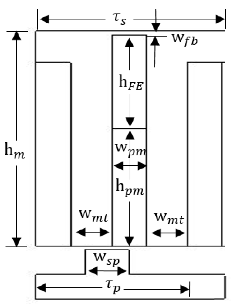
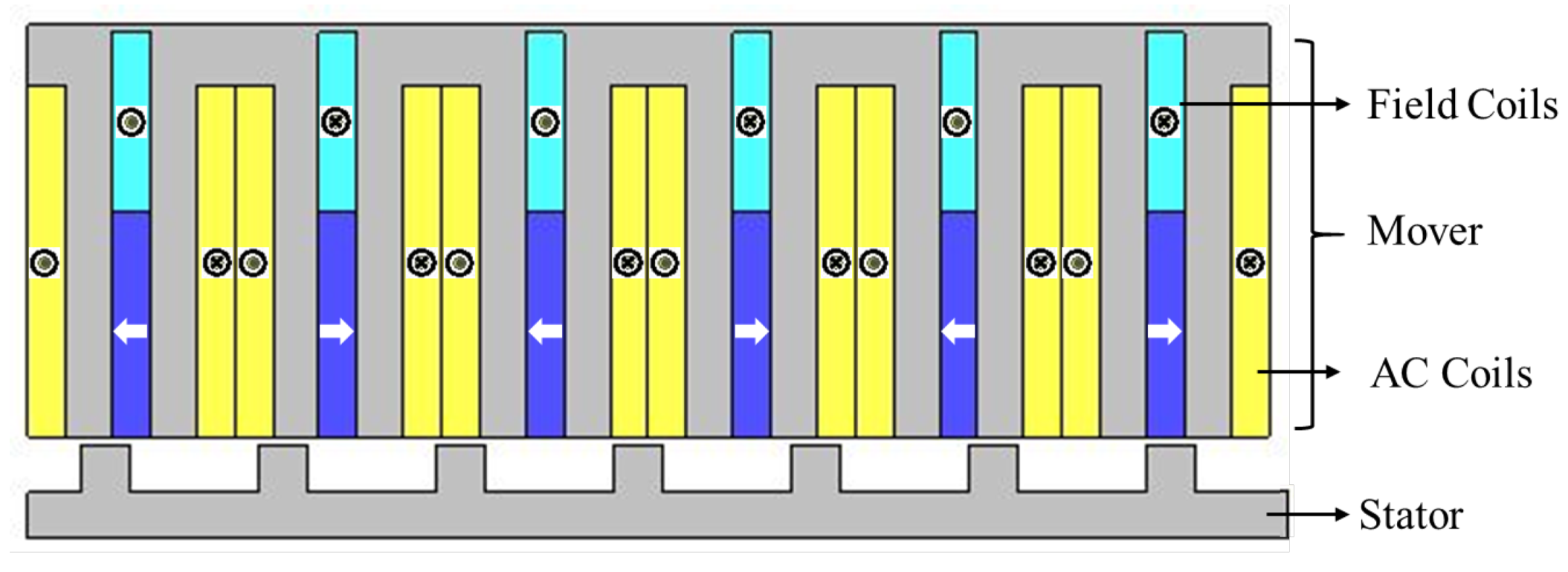
2.1. Machine Topology
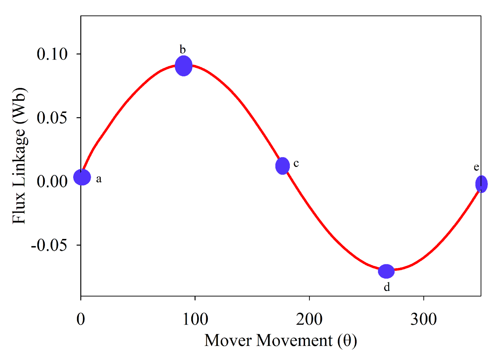
2.2. Operating Principle
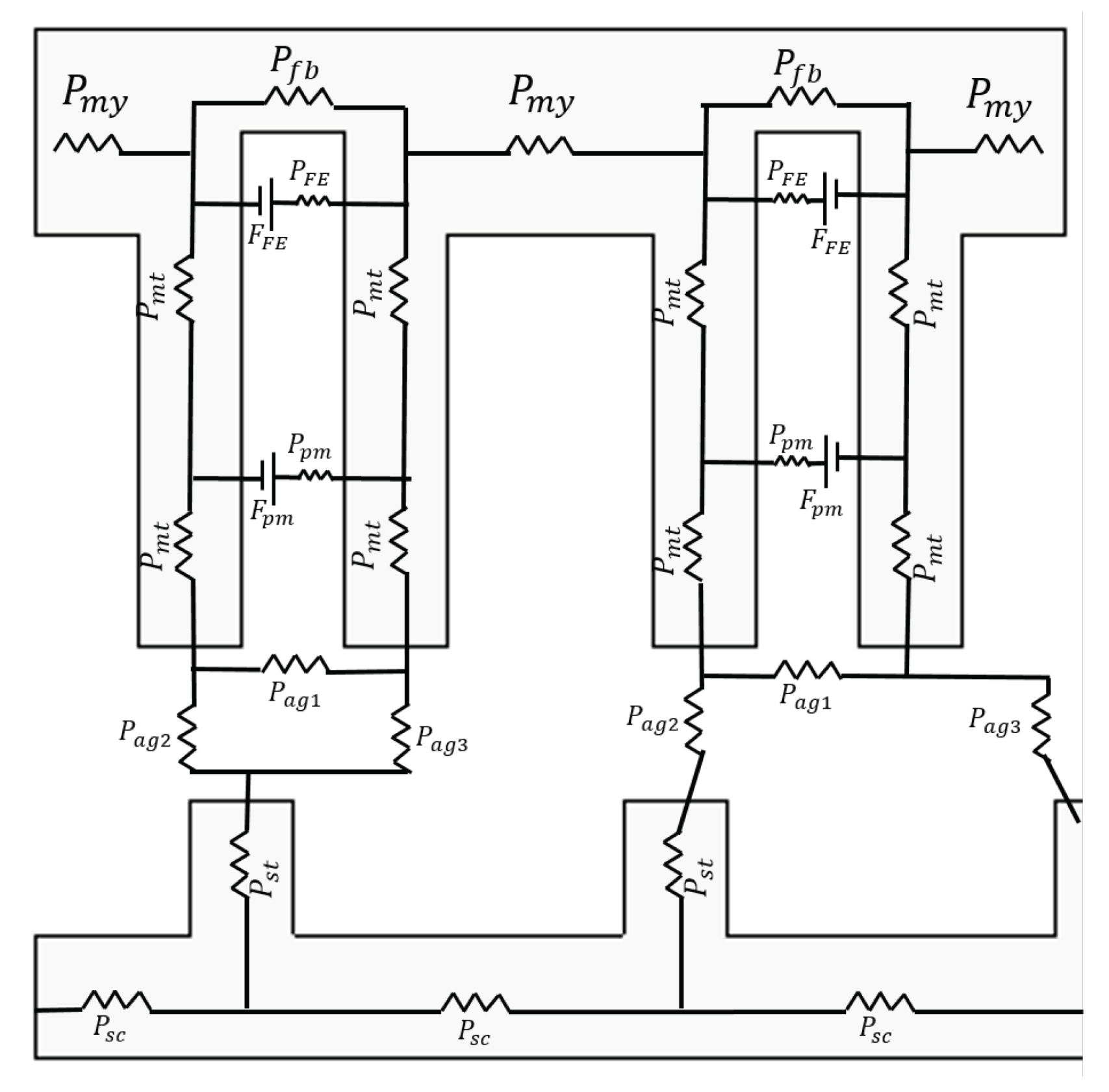
3. Lumped Parameter Model
4. Analysis of Single-Sided VFPMLM
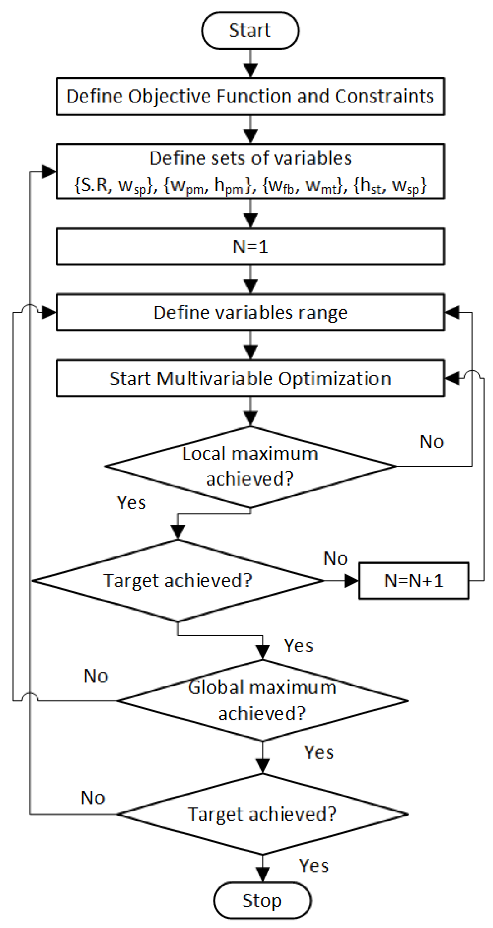
5. Multivariable Geometric Optimization
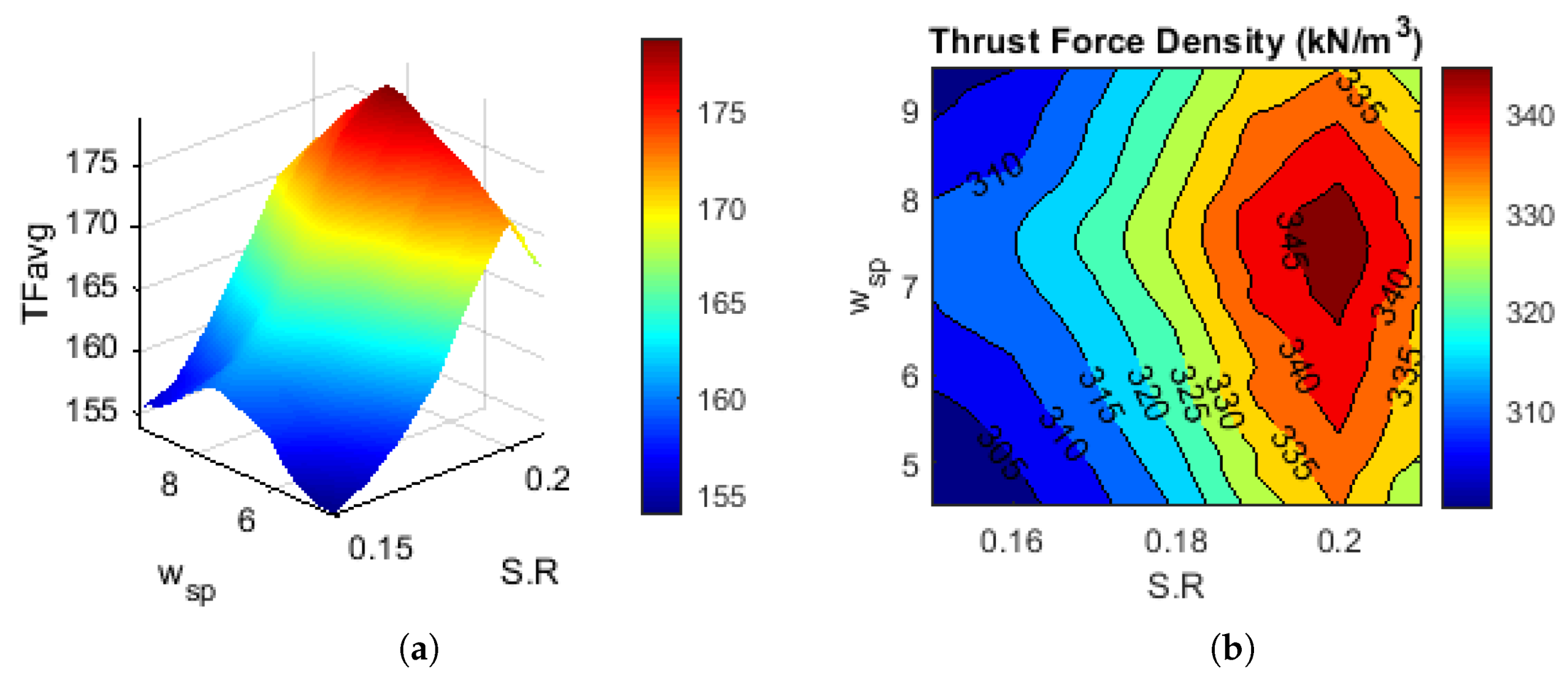
5.1. Influence of and
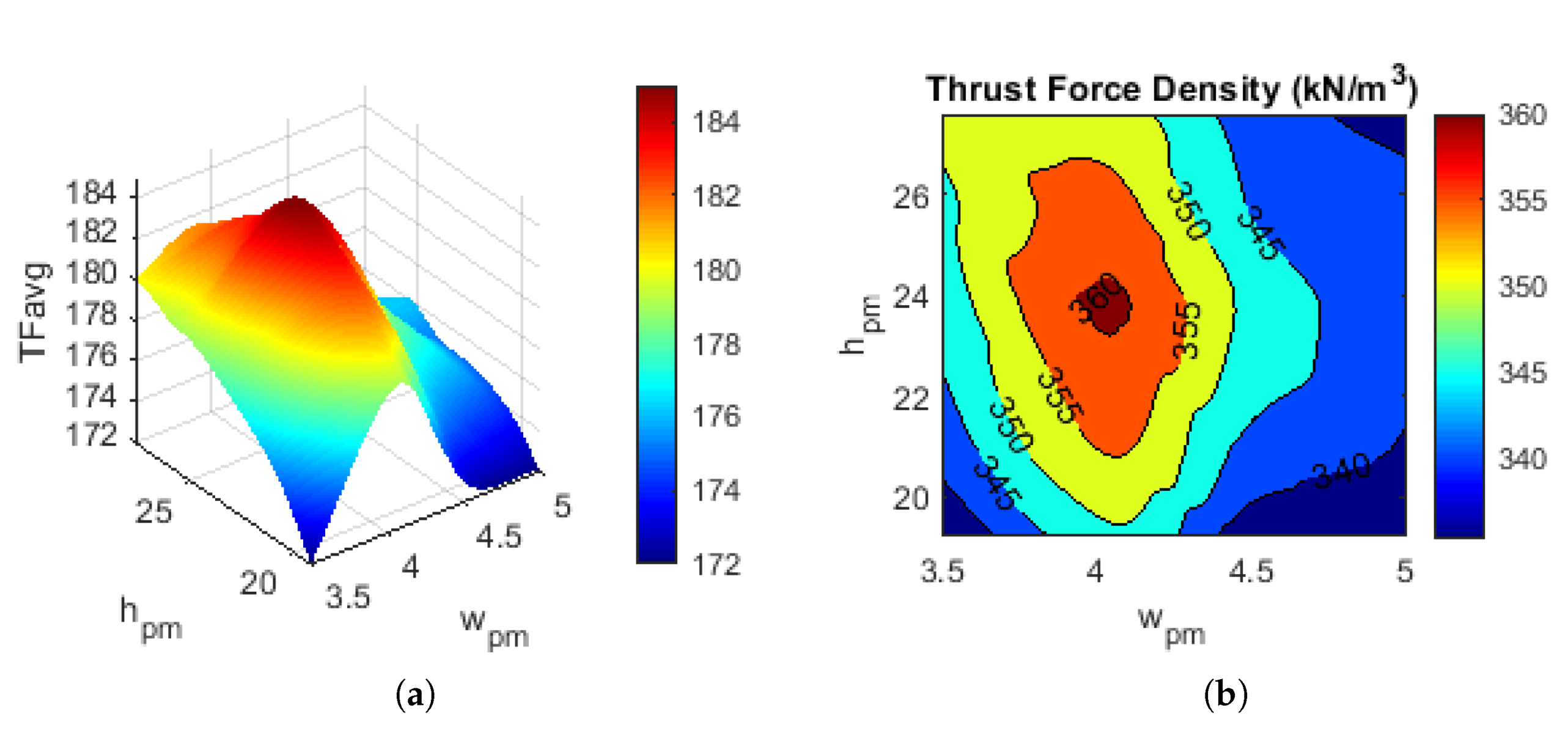
5.2. Influence of and
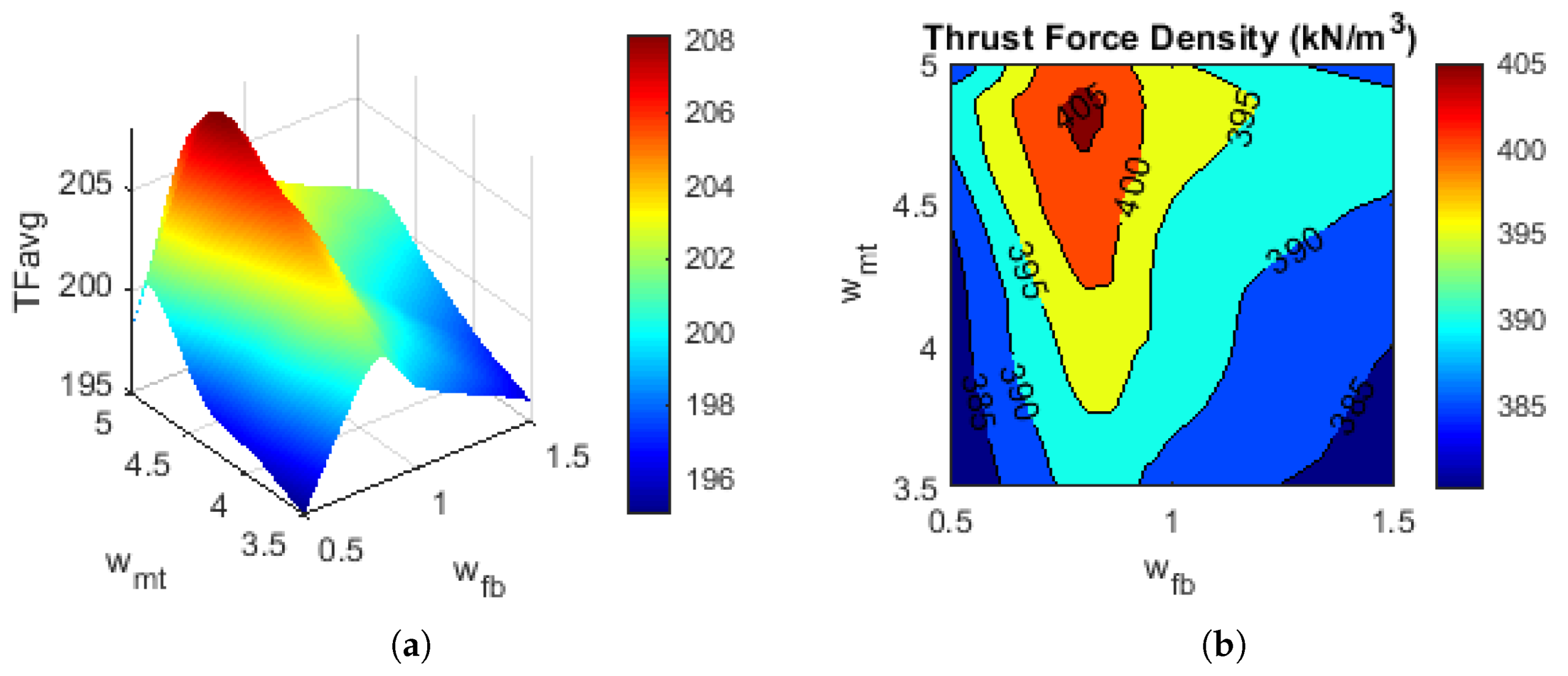
5.3. Influence of and
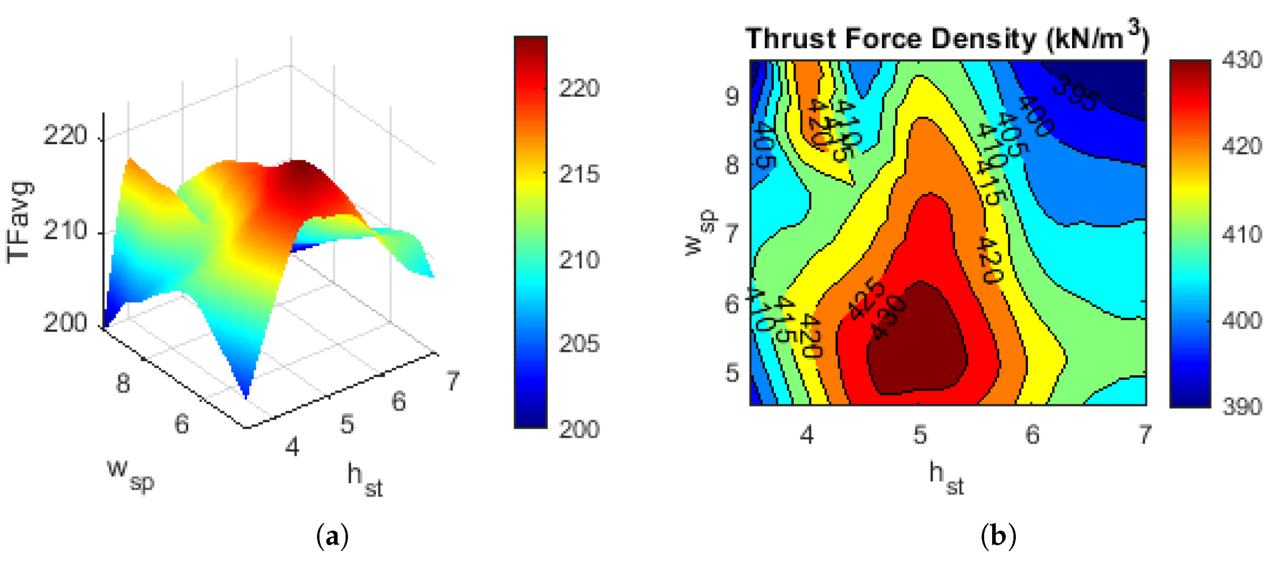
5.4. Influence of and
6. FEA Based Performance Analysis
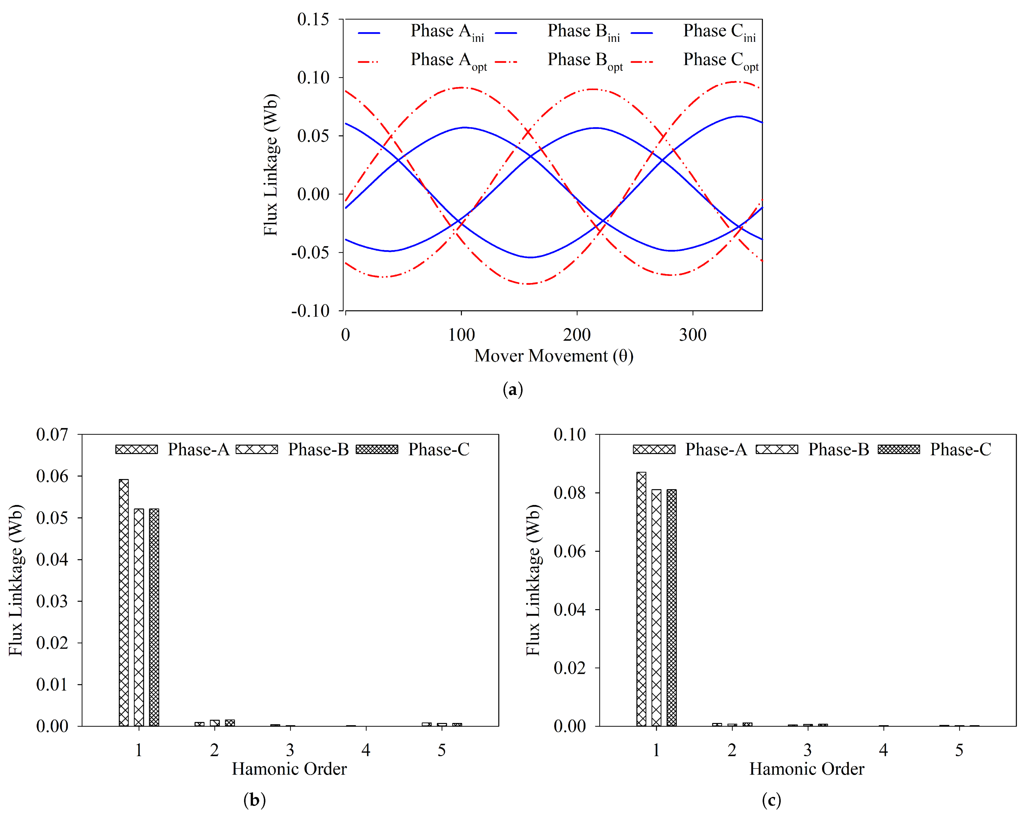
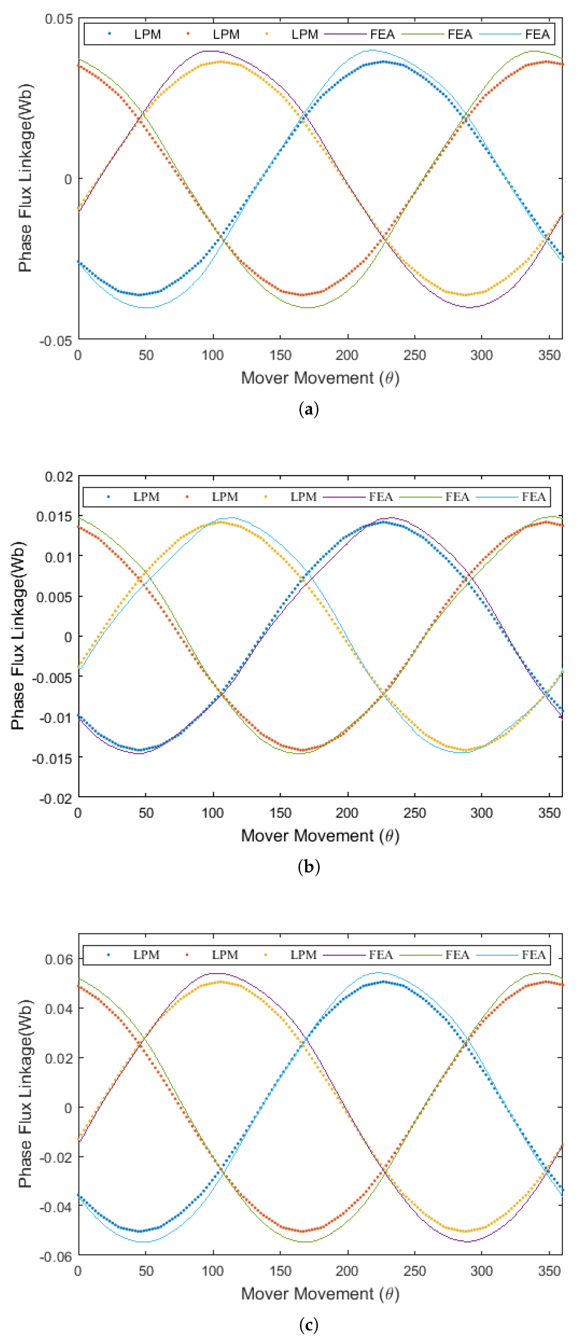
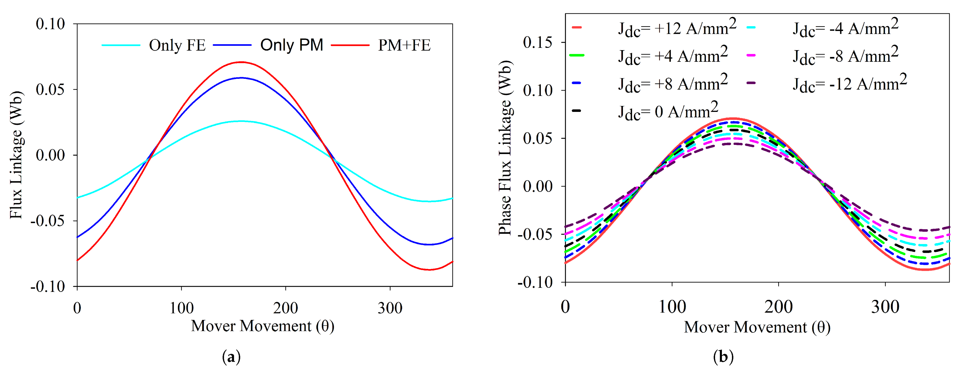
6.1. Flux Strength and Flux Regulation
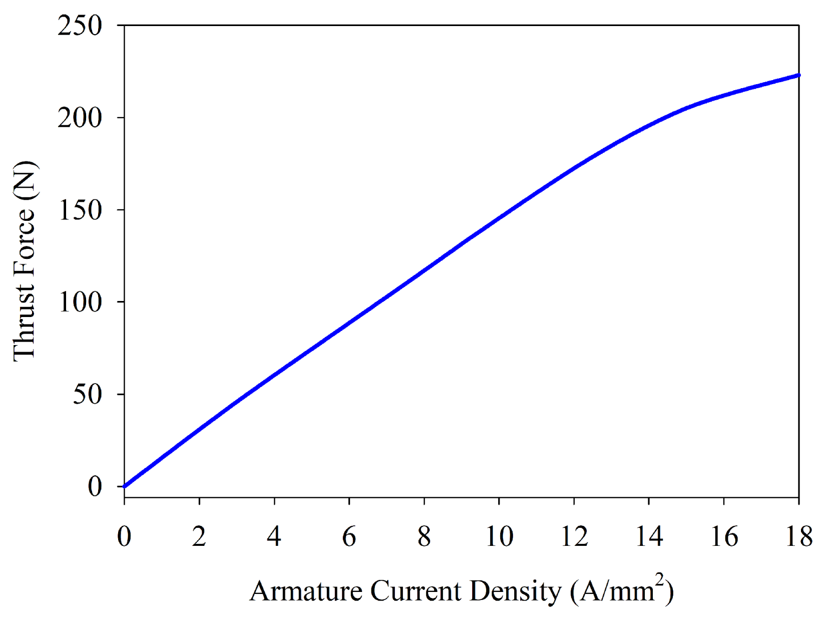
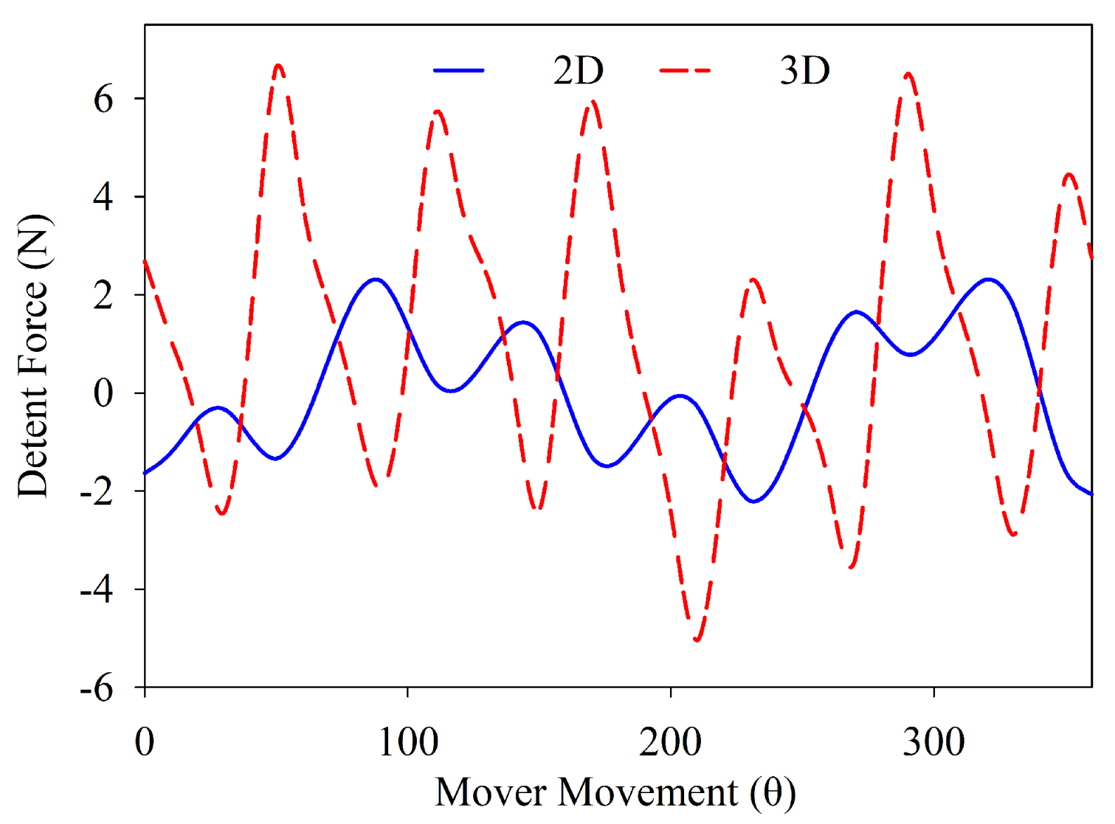
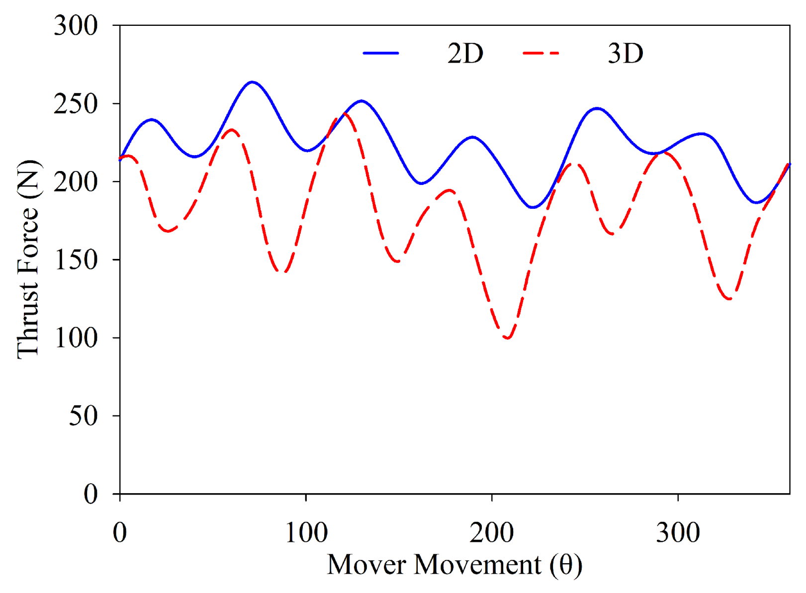
6.2. Detent Force and Average Thrust Force
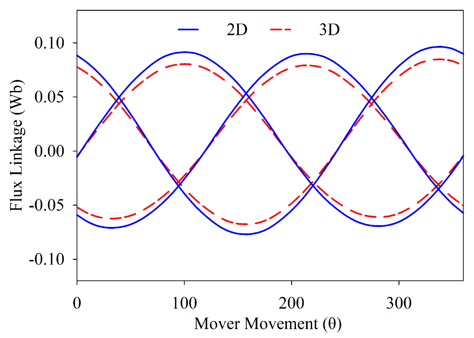
6.3. 3D Analysis
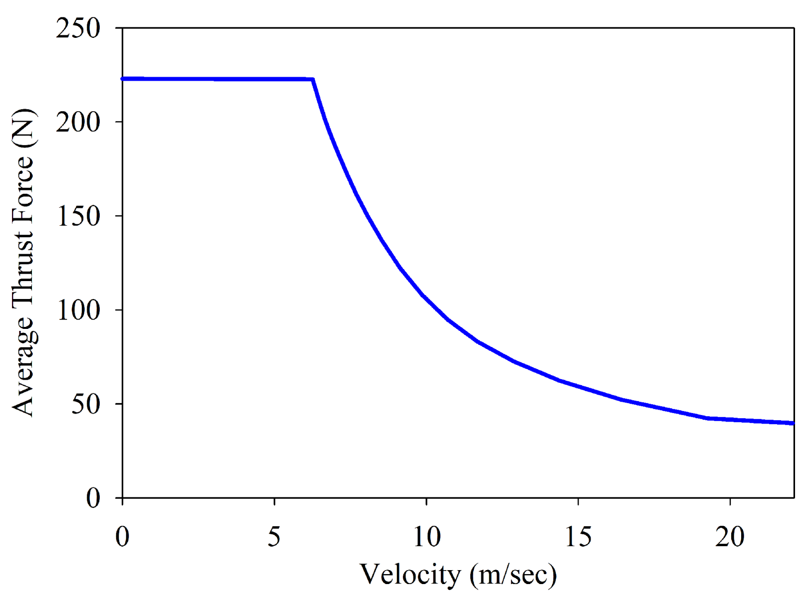
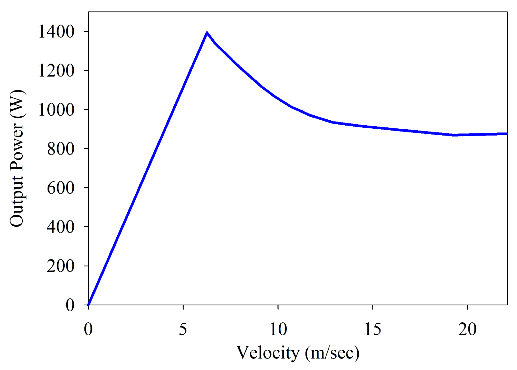
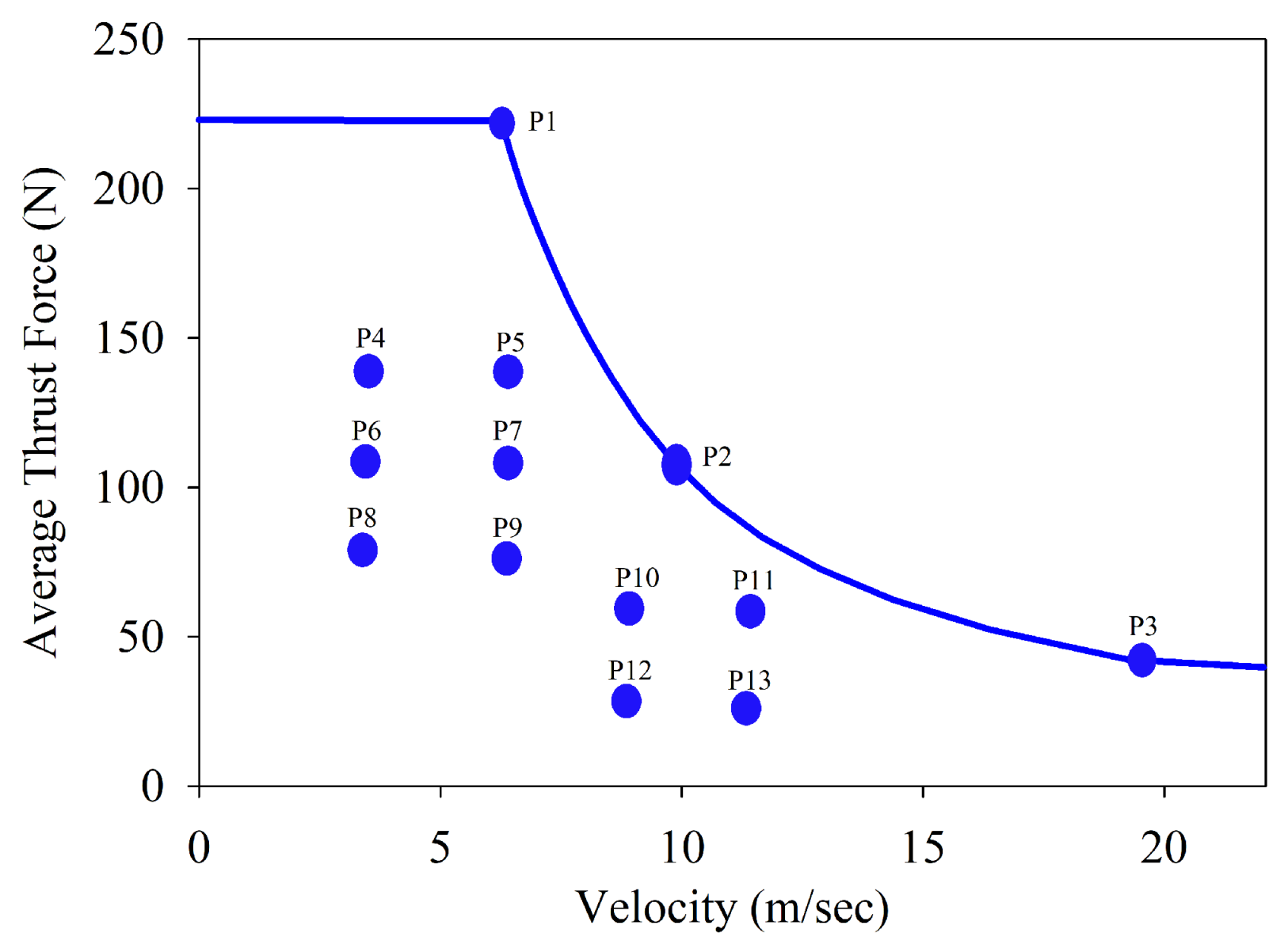
6.4. Force-Velocity and Power-Velocity Characteristic Curve
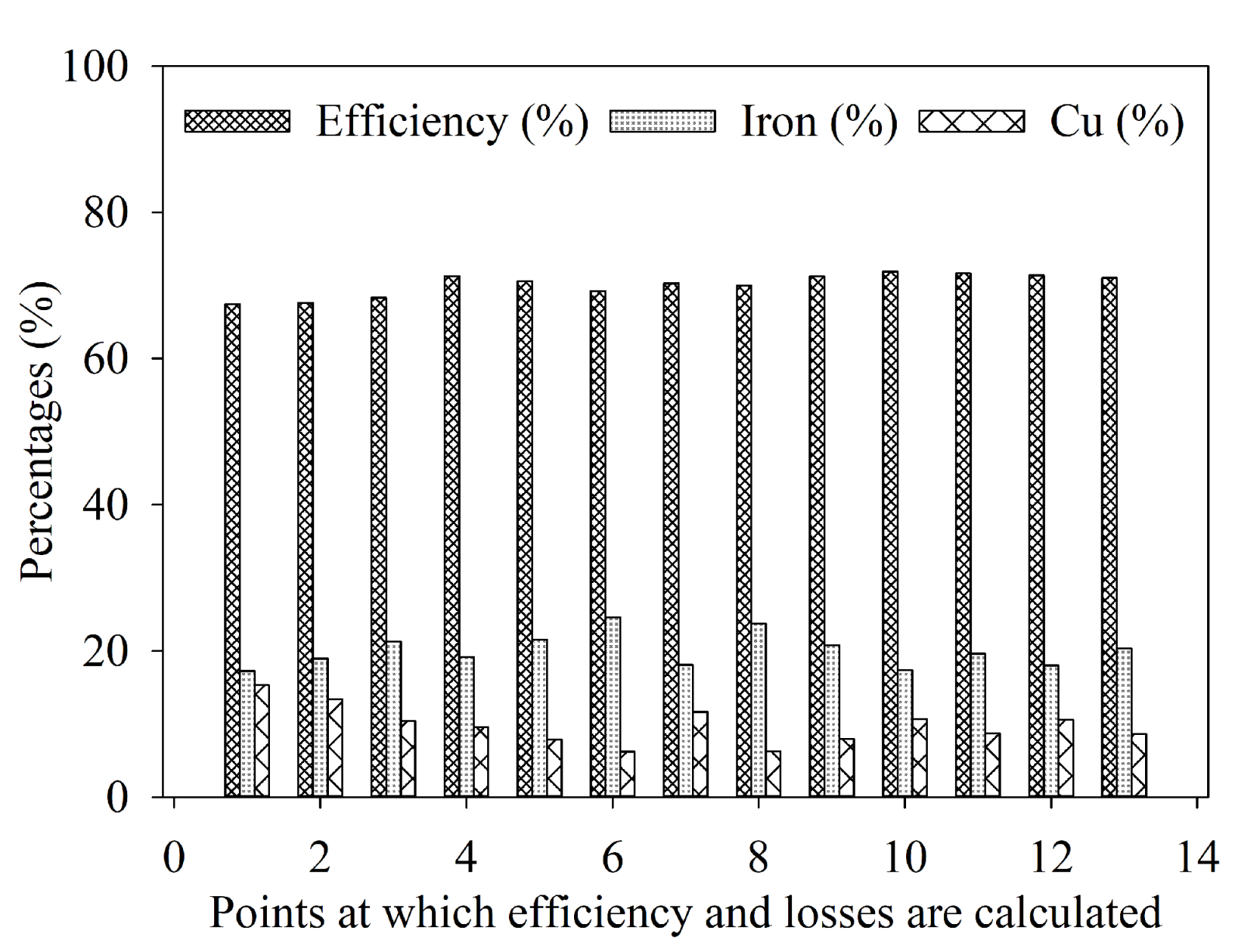
6.5. Efficiency Analysis
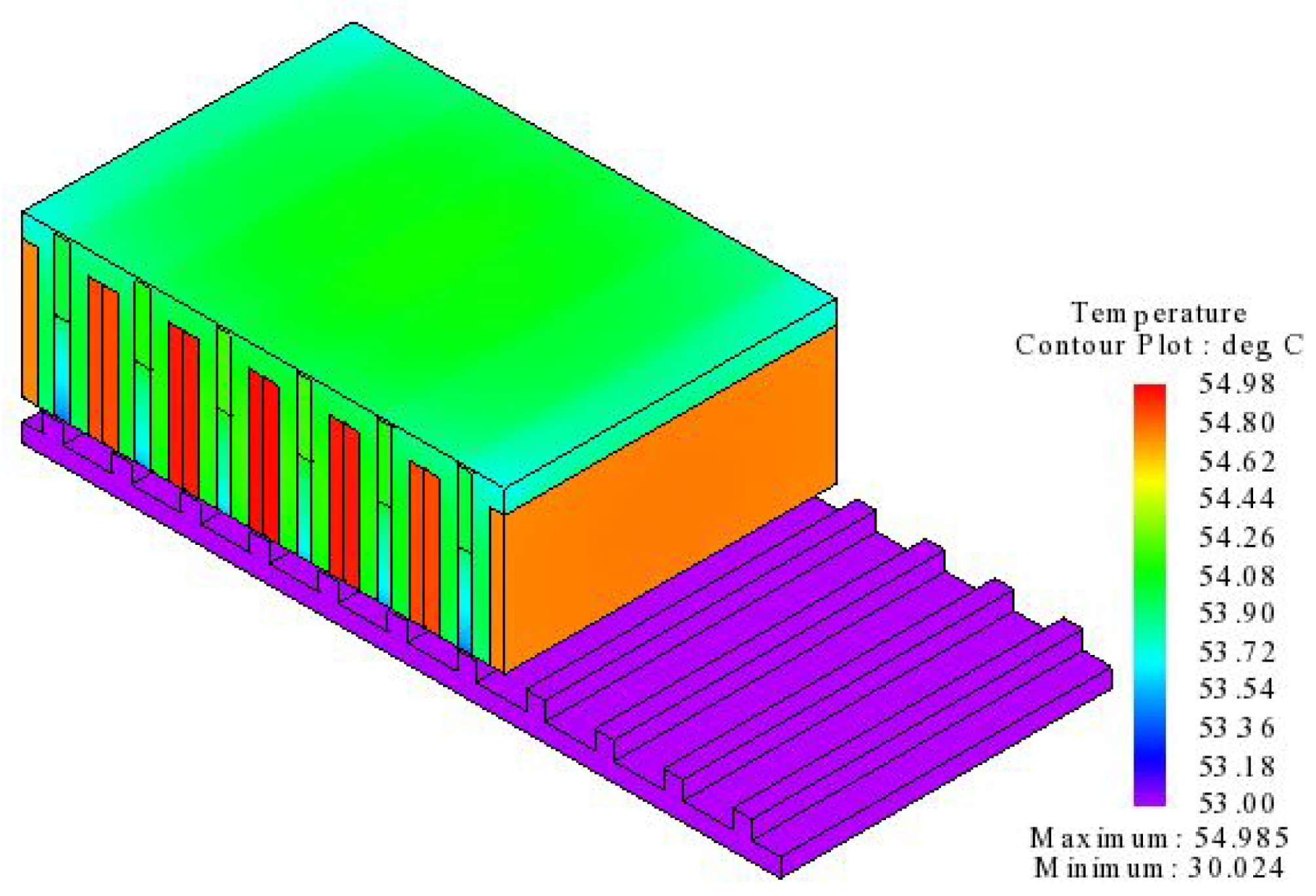
6.6. Thermal Analysis
6.7. Comparison with Conventional Model
7. Conclusions
Author Contributions
Funding
Acknowledgments
Conflicts of Interest
Nomenclature
| flux source | |
| P | permeance |
| F | magneto motive force (mmf) |
| PM mmf | |
| PM remanence | |
| length of PM | |
| relative permeability | |
| FE mmf | |
| field excitation current | |
| PM permeance | |
| mover yoke permeance | |
| flux bridge permeance | |
| secondry tooth permeance | |
| mover tooth permeance | |
| secondary core permeance | |
| length of iron part | |
| magnetic field intensity | |
| magnetic potential drop | |
| magnetization saturation | |
| materials constant | |
| magnetic flux density |
References
- Jin, M.J.; Wang, C.F.; Shen, J.X.; Xia, B. A modular permanent-magnet flux-switching linear machine with fault-tolerant capability. IEEE Trans. Magn. 2009, 45, 3179–3186. [Google Scholar] [CrossRef]
- Huang, L.; Yu, H.; Hu, M.; Liu, H. Study on a long primary flux-switching permanent magnet linear motor for electromagnetic launch systems. IEEE Trans. Plasma Sci. 2013, 41, 1138–1144. [Google Scholar] [CrossRef]
- Zhou, G.; Huang, X.; Jiang, H.; Tan, L.; Dong, J. Analysis method to a Halbach PM ironless linear motor with trapezoid windings. IEEE Trans. Magn. 2011, 47, 4167–4170. [Google Scholar] [CrossRef]
- Mirzaei, M.; Abdollahi, S.E.; Lesani, H. A large linear interior permanent magnet motor for electromagnetic launcher. IEEE Trans. Plasma Sci. 2011, 39, 1566–1570. [Google Scholar] [CrossRef]
- Zhu, Z.; Chen, J.; Pang, Y.; Howe, D.; Iwasaki, S.; Deodhar, R. Analysis of a novel multi-tooth flux-switching PM brushless AC machine for high torque direct-drive applications. IEEE Trans. Magn. 2008, 44, 4313–4316. [Google Scholar] [CrossRef]
- Hellinger, R.; Mnich, P. Linear motor-powered transportation: History, present status, and future outlook. Proc. IEEE 2009, 97, 1892–1900. [Google Scholar] [CrossRef]
- Cao, R.; Lu, M.; Jiang, N.; Cheng, M. Comparison between linear induction motor and linear flux-switching permanent-magnet motor for railway transportation. IEEE Trans. Ind. Electron. 2019, 66, 9394–9405. [Google Scholar] [CrossRef]
- Azer, P.; Bilgin, B.; Emadi, A. Mutually Coupled Switched Reluctance Motor: Fundamentals, Control, Modeling, State of the Art Review and Future Trends. IEEE Access 2019, 7, 100099–100112. [Google Scholar] [CrossRef]
- Wang, H.; Li, J.; Qu, R.; Lai, J.; Huang, H.; Liu, H. Study on high efficiency permanent magnet linear synchronous motor for maglev. IEEE Trans. Appl. Supercond. 2018, 28, 1–5. [Google Scholar] [CrossRef]
- Zhao, W.; Cheng, M.; Ji, J.; Cao, R.; Du, Y.; Li, F. Design and analysis of a new fault-tolerant linear permanent-magnet motor for maglev transportation applications. IEEE Trans. Appl. Supercond. 2012, 22, 5200204. [Google Scholar] [CrossRef]
- Cao, R.; Cheng, M.; Mi, C.; Hua, W.; Wang, X.; Zhao, W. Modeling of a complementary and modular linear flux-switching permanent magnet motor for urban rail transit applications. IEEE Trans. Energy Convers. 2012, 27, 489–497. [Google Scholar] [CrossRef]
- Cao, R.; Cheng, M.; Hua, W. Investigation and general design principle of a new series of complementary and modular linear FSPM motors. IEEE Trans. Ind. Electron. 2012, 60, 5436–5446. [Google Scholar] [CrossRef]
- Zhou, Y.; Zhu, Z. Comparison of wound-field switched-flux machines. IEEE Trans. Ind. Appl. 2014, 50, 3314–3324. [Google Scholar] [CrossRef]
- Abdollahi, S.E.; Vaez-Zadeh, S. Back EMF analysis of a novel linear flux switching motor with segmented secondary. IEEE Trans. Magn. 2013, 50, 1–9. [Google Scholar] [CrossRef]
- Ullah, N.; Basit, A.; Khan, F.; Shah, Y.A.; Khan, A.; Waheed, O.; Usman, A. Design and Optimization of Complementary Field Excited Linear Flux Switching Machine With Unequal Primary Tooth Width and Segmented Secondary. IEEE Access 2019, 7, 106359–106371. [Google Scholar] [CrossRef]
- Liu, C.T.; Hwang, C.C.; Li, P.L.; Hung, S.S.; Wendling, P. Design optimization of a double-sided hybrid excited linear flux switching PM motor with low force ripple. IEEE Trans. Magn. 2014, 50. [Google Scholar] [CrossRef]
- Gandhi, A.; Parsa, L. Hybrid flux-switching linear machine with fault-tolerant capability. In Proceedings of the 2015 IEEE International Electric Machines & Drives Conference (IEMDC), Coeur d’Alene, ID, USA, 10–13 May 2015; pp. 715–720. [Google Scholar]
- Hwang, C.C.; Li, P.L.; Liu, C.T. Design and analysis of a novel hybrid excited linear flux switching permanent magnet motor. IEEE Trans. Magn. 2012, 48, 2969–2972. [Google Scholar] [CrossRef]
- Xu, L.; Zhao, W.; Ji, J.; Liu, G.; Du, Y.; Fang, Z.; Mo, L. Design and analysis of a new linear hybrid excited flux reversal motor with inset permanent magnets. IEEE Trans. Magn. 2014, 50. [Google Scholar] [CrossRef]
- Zeng, Z.; Lu, Q.; Ye, Y. Optimization design of E-core hybrid-excitation linear switched-flux permanent magnet machine. Int. J. Appl. Electromagn. Mech. 2017, 54, 351–366. [Google Scholar] [CrossRef]
- Sulaiman, E.; Kosaka, T.; Matsui, N. Design and performance of 6-slot 5-pole PMFSM with hybrid excitation for hybrid electric vehicle applications. In Proceedings of the 2010 International Power Electronics Conference-ECCE ASIA, Sapporo, Japan, 21–24 June 2010; pp. 1962–1968. [Google Scholar]
- Gaussens, B.; Hoang, E.; Lécrivain, M.; Manfe, P.; Gabsi, M. A hybrid-excited flux-switching machine for high-speed DC-alternator applications. IEEE Trans. Ind. Electron. 2013, 61, 2976–2989. [Google Scholar] [CrossRef] [Green Version]
- Hua, W.; Zhang, G.; Cheng, M. Flux-regulation theories and principles of hybrid-excited flux-switching machines. IEEE Trans. Ind. Electron. 2015, 62, 5359–5369. [Google Scholar] [CrossRef]
- Hua, H.; Zhu, Z. Novel partitioned stator hybrid excited switched flux machines. IEEE Trans. Energy Convers. 2017, 32, 495–504. [Google Scholar] [CrossRef]
- Zhang, L.; Fan, Y.; Lorenz, R.D.; Cui, R.; Li, C.; Cheng, M. Design and analysis of a new five-phase brushless hybrid-excitation fault-tolerant motor for electric vehicles. IEEE Trans. Ind. Appl. 2017, 53, 3428–3437. [Google Scholar] [CrossRef]
- Gao, Y.; Li, D.; Qu, R.; Fan, X.; Li, J.; Ding, H. A novel hybrid excitation flux reversal machine for electric vehicle propulsion. IEEE Trans. Veh. Technol. 2017, 67, 171–182. [Google Scholar] [CrossRef]
- Zhu, Z.; Pang, Y.; Howe, D.; Iwasaki, S.; Deodhar, R.; Pride, A. Analysis of electromagnetic performance of flux-switching permanent-magnet machines by nonlinear adaptive lumped parameter magnetic circuit model. IEEE Trans. Magn. 2005, 41, 4277–4287. [Google Scholar] [CrossRef]
- Ullah, W.; Khan, F.; Umair, M. Lumped parameter magnetic equivalent circuit model for design of segmented PM consequent pole flux switching machine. Eng. Comput. 2020, 38, 572–585. [Google Scholar] [CrossRef]
- Chen, A.; Nilssen, R.; Nysveen, A. Analytical design of a high-torque flux-switching permanent magnet machine by a simplified lumped parameter magnetic circuit model. In Proceedings of the XIX International Conference on Electrical Machines-ICEM 2010, Rome, Italy, 6–8 September 2010; pp. 1–6. [Google Scholar]
- Qi, G.; Chen, J.; Zhu, Z.; Howe, D.; Zhou, L.; Gu, C. Influence of skew and cross-coupling on flux-weakening performance of permanent-magnet brushless AC machines. IEEE Trans. Magn. 2009, 45, 2110–2117. [Google Scholar] [CrossRef] [Green Version]
- Zhu, Z.; Shuraiji, A.L.; Lu, Q. Comparative study of tubular partitioned stator permanent magnet machines. In Proceedings of the 2015 Tenth International Conference on Ecological Vehicles and Renewable Energies (EVER), Monte Carlo, Monaco, 31 March–2 April 2015; pp. 1–7. [Google Scholar]
- Hua, H.; Zhu, Z.; Zhan, H. Novel consequent-pole hybrid excited machine with separated excitation stator. IEEE Trans. Ind. Electron. 2016, 63, 4718–4728. [Google Scholar] [CrossRef]
- Zhao, J.; Guan, X.; Li, C.; Mou, Q.; Chen, Z. Comprehensive evaluation of inter-turn short circuit faults in PMSM used for electric vehicles. IEEE Trans. Intell. Transp. Syst. 2020, 22, 611–621. [Google Scholar] [CrossRef]


| Symbol | Description | Unit | Dimension |
|---|---|---|---|
| mover height | mm | 43.5 | |
| whole mover length | mm | 131 | |
| mover pole pitch | mm | 21.84 | |
| AC slot height | mm | 33.4 | |
| DC slot height | mm | 19.5 | |
| PM height | mm | 24 | |
| flux bridge width | mm | 1 | |
| AC turns | – | 220 | |
| DC turns | – | 50 | |
| velocity | m/sec | 4 | |
| air gap | mm | 0.8 | |
| L | stack length | mm | 90 |
| stator pole pitch | mm | 18.72 | |
| Stator pole width | mm | 8.42 | |
| winding filling factor | – | 0.5 | |
| FE current | Amps | 6 |
| Pole/Slot Combination | Thrust Force | Detent Force |
|---|---|---|
| 5/6 | 112.714 N | 76.59 N |
| 7/6 | 165.212 N | 36.05 N |
| 8/6 | Bipolar Force | – |
| 10/6 | Bipolar Force | – |
| 11/6 | 139.653 N | 49.01 N |
| 13/6 | 65.42 N | 9.53 N |
| Analysis Method | Time | Drive Storage |
|---|---|---|
| LPM | 4.67 s | 126 KBs |
| 2D FEA | 7 min and 48 s | 217 MBs |
| Parameter | Initial Values | Optimized Values | Improvements |
|---|---|---|---|
| Flux Linkage (Wb) | 0.12112 | 0.17455 | 44.11% |
| THD (%) | 3.47 | 1.27 | 63.40% |
| Detent Force (N) | 36.05 | 4.51 | 87.49% |
| (N) | 165.21 | 223.04 | 35.0% |
| TFD (kN/m) | 322 | 434.76 | 35.02% |
| (N) | 60 | 46 | 23.33% |
| Parameter | Proposed | Conventional |
|---|---|---|
| Mover length | 131 mm | 131 mm |
| Machine total height | 54.3 mm | 54.3 mm |
| Stack Length | 90 mm | |
| Air gap | 0.8 mm | |
| No. of armature slots | 6 | |
| No. of DC slots | 3 | 7 |
| Field Current | 6 A | |
| Armature Turns | 226 | 276 |
| DC Turns | 51 | 81 |
| Thrust Force | 223.04 N | 153.45 N |
| per PM Volume | 4.302 N/cm | 2.77 N/cm |
| TFD | 434.76 kN/m | 265.325 kN/m |
Publisher’s Note: MDPI stays neutral with regard to jurisdictional claims in published maps and institutional affiliations. |
© 2021 by the authors. Licensee MDPI, Basel, Switzerland. This article is an open access article distributed under the terms and conditions of the Creative Commons Attribution (CC BY) license (https://creativecommons.org/licenses/by/4.0/).
Share and Cite
Ullah, B.; Khan, F.; Qasim, M.; Khan, B.; Milyani, A.H.; Cheema, K.M.; Din, Z. Lumped Parameter Model and Electromagnetic Performance Analysis of a Single-Sided Variable Flux Permanent Magnet Linear Machine. Energies 2021, 14, 5494. https://doi.org/10.3390/en14175494
Ullah B, Khan F, Qasim M, Khan B, Milyani AH, Cheema KM, Din Z. Lumped Parameter Model and Electromagnetic Performance Analysis of a Single-Sided Variable Flux Permanent Magnet Linear Machine. Energies. 2021; 14(17):5494. https://doi.org/10.3390/en14175494
Chicago/Turabian StyleUllah, Basharat, Faisal Khan, Muhammad Qasim, Bakhtiar Khan, Ahmad H. Milyani, Khalid Mehmood Cheema, and Zakiud Din. 2021. "Lumped Parameter Model and Electromagnetic Performance Analysis of a Single-Sided Variable Flux Permanent Magnet Linear Machine" Energies 14, no. 17: 5494. https://doi.org/10.3390/en14175494
APA StyleUllah, B., Khan, F., Qasim, M., Khan, B., Milyani, A. H., Cheema, K. M., & Din, Z. (2021). Lumped Parameter Model and Electromagnetic Performance Analysis of a Single-Sided Variable Flux Permanent Magnet Linear Machine. Energies, 14(17), 5494. https://doi.org/10.3390/en14175494