Article

Propagation of Cryogenic Thermal Fractures from Unconfined PMMA Boreholes

1
Department of Civil Engineering, Jeju National University, Jeju-si 63243, Korea
2
Carbon Capture, Utilization, and Storage Research Center, King Abdulaziz City for Science and Technology (KACST), Riyadh 11442, Saudi Arabia
3
Department of Petroleum Engineering, Colorado School of Mines, 1600 Arapahoe St., Golden, CO 80401, USA
4
School of Mining & Geosciences, Nazarbayev University, Qabanbay Batyr Ave 53, Nur-Sultan City 010000, Kazakhstan
5
Hydrocarbon Resources Program, Lawrence Berkeley National Laboratory, 1 Cyclotron Road, Berkeley, CA 94720, USA
*
Author to whom correspondence should be addressed.
Energies 2021, 14(17), 5433; https://doi.org/10.3390/en14175433
Submission received: 5 July 2021 / Revised: 10 August 2021 / Accepted: 26 August 2021 / Published: 1 September 2021

Abstract

:
In cryogenic fracturing, a rock surface exposed to cryogenic fluids undergoes a large thermal gradient, and the resultant local tensile stress overcomes rock strength and initiates fractures. This study investigates the development of cracks generated from the cryogenic treatment of a borehole under no external confining stress on specimens. The experiments were performed on transparent PMMA specimens to observe fracture proliferation around boreholes. Liquid nitrogen was flowed through the boreholes to cool the borehole surface. The results show that initial fracture growth is characterized by abrupt starts and stops, and as the fracture propagates outward, the growth appears more continuous. In an early stage, horizontal/radial fractures and vertical fractures are the defining patterns. Horizontal fractures tend to be separated by a specific exclusion distance (i.e., spacing between cracks). While distinct horizontal/vertical fractures and exclusion distance manifest themselves at an early stage, fractures resulting from fracture interactions and curvatures can develop into complex shapes at later stages. Cryogenic thermal loading induces distinctively curved fractures. The tendency of curvature may prevent greater penetration. An increase in the borehole pressure during liquid nitrogen flow, however, can lessen fracture tortuosity and facilitate radial propagation. A high flow pressure and rate are also advantageous in that they accelerate cooling and fracture propagation.

1. Introduction

Cryogenic fracturing exerts a large thermal gradient on near-borehole formations by creating contact between a cryogen and a much warmer rock under reservoir conditions to induce fractures. A cryogen, such as liquid nitrogen (LN), takes a liquid form at low temperatures and transforms into the gaseous phase in standard conditions. Specifically, when LN is injected into a borehole in which the temperature is much higher, the heat from the rock will quickly transfer to the LN and boil it (the boiling point of LN at atmospheric pressure is −195.8 °C). This rapid cooling, or thermal shock, will cause the near-borehole reservoir rock to contract and create local tensile stress. An increase in the tensile stress to a sufficiently high level will initiate fractures orthogonal to the rock surface. These newly induced fractures may extend even farther by high-pressure gas generated by LN vaporization. Note that nitrogen has a liquid-to-gas expansion ratio of 1:694 at room temperature (20 °C) and atmospheric pressure.
Extensive laboratory and numerical studies have been conducted to explain cryogenic fracturing and its implications for the field [1]. LN cooling decreases tensile, compressive and shear strength, elastic modulus, and P-wave velocity [2,3] and induces a moderate decrease in the stability of bedding planes and a relative increase in the propagation ability of fractures [3]. Cryogenic treatments increase the pore size in saturated sandstone and expand micro-fissures, resulting from thermal stress and frost force; they can also be influenced by the rock type and water content [4]. The shale pore structure undergoes significant alteration after freeze–thaw cycles, and some micro-pores are aggregated to form micro- and macro-cracks [3]. Although LN cooling increases permeability [2,5,6], it is less effective for sandstone than it is for other sedimentary rocks [7,8]. The surface micro-structure of rocks raises the Leidenfrost point, thus shortening the duration of film boiling and increasing the rate of cooling. Appropriately modifying the rock surface can further enhance quenching rates [9].
Cryogenic treatment creates a strong thermal gradient and local tensile stress in the rocks surrounding existing main fractures [10]. A faster cooling rate generates higher tensile stress in the exterior region of rocks and higher tensile hoop stress [2,11]. Conductive cracks are also generated on the surface and near the wellbore of shale, and the size and number of these cracks increase with initial temperature, and most of the cooling-induced cracks are inter-granular cracks [2,11,12]. Micro-cracks, or secondary cracks, perpendicular to the joints or primary fractures can be generated in a reservoir, creating a larger and more complex fracture network than the stimulation reservoir volume (SRV) in hydraulic fracturing [1,3,4]. The density and brittleness of fractures in sandstone, shale, and marble at cryogenic temperature under tensile loading markedly increase, promoting the generation of complex fracture networks with a larger volume [13,14]. Phase transition during the fracturing process and the low fluid viscosity of LN can facilitate fracture propagation and network generation [11]. The fracability of shale increases after LN pretreatment, especially under high confining pressure conditions, and after LN treatment, the strength and brittleness of shale decrease, which reduces the initiation and propagation pressure of reservoir stimulation [3,14,15].
Studies have also examined cryogenic fracturing stimulation to determine its effectiveness at building enhanced geothermal systems in hot dry rock. Their results have shown that LN cooling improves permeability while causing noticeable cracks in hot rock [16,17]. With increasing initial rock temperature, the number of thermal cracks increases, and a more complex crack network forms [16]. Inter-granular cracking is the primary failure mode during thermal treatment [17]. As heating temperature increases, reductions in strength, elastic modulus, and P-wave velocities become more pronounced [17]. Heating and cooling cycles accelerate the mechanical deterioration of granite and augment permeability, which mainly occur during the initial few cycles, and elevating the heating temperature in cycles increases the damage rate of granite [18]. Compared to an abrasive water jet, an abrasive LN jet, which creates a larger and more irregular cavity with lower threshold pressure, exhibits better performance in perforation [19,20]. A high initial rock temperature and a short perforation length can increase thermal stresses [19]. In addition, nozzle pressure drop affects the depth, diameter, and stress-dependent shape of the cavities, while the nozzle diameter affects the cavity-opening diameter. Increasing the abrasive particle diameter and rock temperature increases both the cavity-opening diameter and the cavity depth [20].
However, there is limited insight into how cryogenic fractures propagate from wellbores. Although studies have performed the visualization of thermal crack propagation in simple 1D or 2D geometries [21,22,23], none have attempted to explain the process of cryogenic fracturing propagating over time from borehole geometry, which is relevant to well stimulation. While reporting some cryogenic fracture patterns, notably tortuosity, the studies inferred them from boundary observations [24,25,26] or post-mortem observations after breakdown tests [15]. That is, the studies involved no real-time observations of internal cryogenic fracturing processes around the boreholes of 3D specimens, an approach similar to the CT-scan monitoring of hydraulic fracturing by de Borst et al. [27]. Rather than flowing cryogen through boreholes, which maximizes the cooling rate and sustains a cryogenic temperature at the boreholes, most studies involved injecting cryogen one way, pressurizing the borehole and thus elevating the temperature, but the borehole temperature was not monitored [11,28,29]. In addition, they did not consider the pressure of the LN flow into the borehole as a parameter in cryogenic fracture propagation.
In response to gaps in the literature, this study investigates the initiation and propagation of cryogenic fractures from and around boreholes with time under LN flow through the boreholes of transparent specimens. By internally observing the 3D transparent specimens with time, we aim to understand the dynamics of the development and morphology of cryogenic fractures around boreholes. We flowed LN through boreholes drilled through the center of transparent PMMA blocks to visualize fracture initiation and propagation. Fracturing processes, temperature, and borehole pressure were recorded during the cryogenic flow to visually assess fracture development and observe the behaviors. This study, performed under no confining stresses, examines two cases of thermal shock with negligible borehole hydraulic loading during thermal flow, and for comparison, one case with thermal shock with hydraulic loading.

2. Laboratory Study

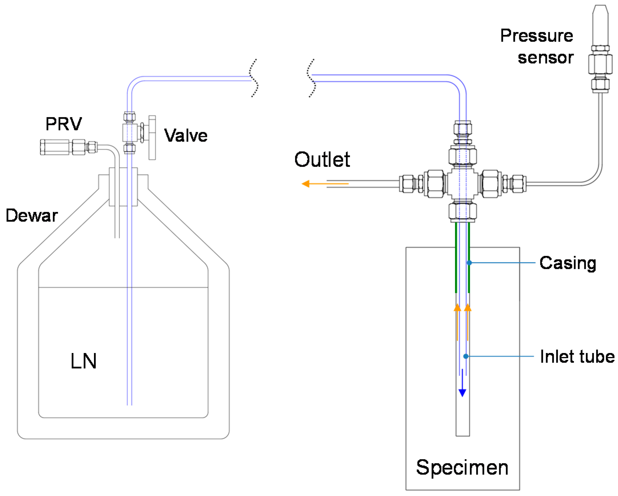
2.1. Devices and Procedure
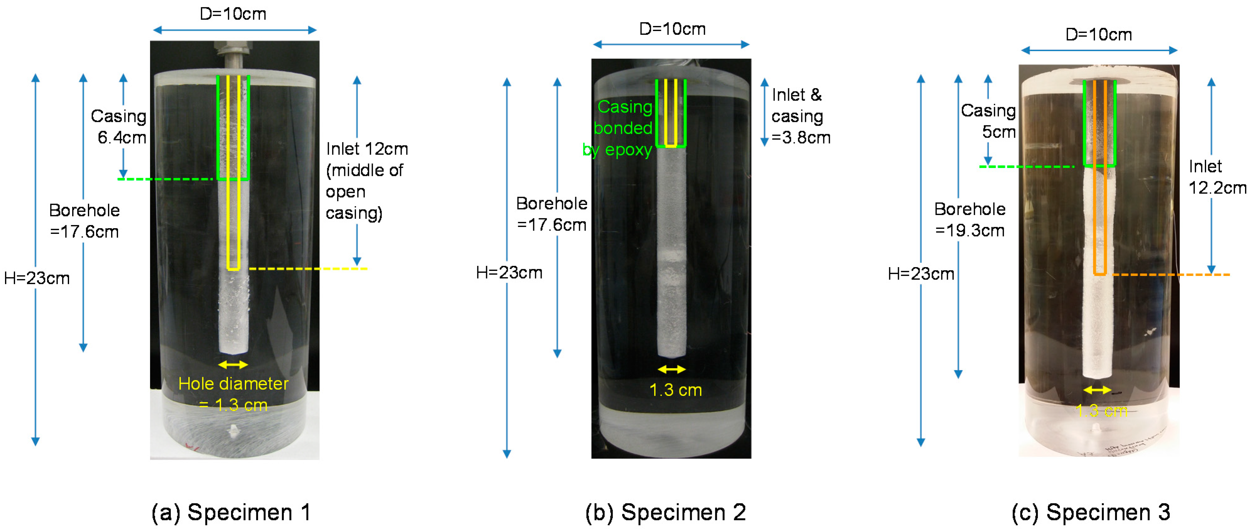
To maximize thermal shock and the thermal gradient on borehole walls, we continuously flushed liquid nitrogen (LN) to cool the borehole as rapidly as possible. LN was pumped from the dewar by a pressure difference using an LN withdrawal device (Figure 1) and was transported through a vacuum-jacketed hose to the specimen and injected into the borehole and then directed to an outlet. For the flow of LN through the borehole, we utilized a coaxial flow design in which LN enters the borehole through the central smaller-diameter inlet tubing (blue tubing and arrows—Figure 1), which passes through a larger-size cross-shaped fitting. Then, warmed nitrogen exits through the annulus between the inlet tubing and the casing, and then through the space in the cross-shaped fitting (Figure 1). Insulation was applied to all transport lines from the dewar to the specimen inlet to reduce heat loss.
Temperature, pressure inside the borehole, and LN consumption were monitored and recorded. Cryogenic temperature was measured by T-type thermocouples (range: −200~150 °C, precision: ±0.5 °C), and its thin wires were selected for prompt response to temperature changes and access to the borehole. The borehole pressure was monitored by attaching a pressure transducer (range: 0–1.4 kPa, accuracy: ±0.25%) at the top of an 8” stainless steel extension tube (1/8” OD) (Figure 1), which created a vapor cushion and dissipated the low temperature, which limited the heat transfer (the temperature was above 0 °C at the top of the tubing throughout the tests). LN consumption was monitored by a dewar placed on a scale (range: 75 kg, repeatability: 0.02 kg). The accuracy of the measurements within a range of ±1% was ensured for all the sensors by checking measurements by other types of sensors and/or known values in certain conditions. For example, the thermocouple measured room air temperature at a difference of less than 1 °C from that measured by a thermometer and measured −195 °C when it was submerged in LN at 1 atm. Images of the specimens were captured by a high-resolution digital camera throughout the experiments. More information about the devices can be found in Cha et al. [30].
In the setup, LN was directly transferred from the dewar to the borehole, and thus the pressure inside the borehole was closely related to the pressure inside the dewar. For Specimen 1–2 tests, cryogenic fracturing was performed by purer thermal shock; the pressure inside the boreholes was less than 50 kPa during the LN flow. For the Specimen 3 test, flow pressure was higher, about 400–500 kPa, and thus the flow rate was higher.

2.2. Specimens

Experiments were performed in poly (methyl methacrylate) (PMMA), a transparent, thermoplastic polymer. An advantage of performing experiments in a transparent specimen is that one can observe fracture proliferation through the media with time. Researchers often use PMMA for hydraulic fracturing tests because of its known physical properties and proximity to shale in terms of its mechanical properties, including its fracture toughness and brittleness [31,32,33]. Table 1 summarizes the mechanical and thermal properties of PMMA at both room temperature and cryogenic temperature as it exhibits temperature-dependent properties. The compressive strength, tensile strength, and elastic modulus of PMMA increase as the temperature decreases [34,35,36]. On the other hand, thermal conductivity, specific heat, and the coefficient of thermal expansion decrease at cryogenic temperature [37,38]. The properties of Niobrara shale, nitrogen, and water are compared in Table 1. In addition to the differences in the material properties, Niobrara shale consists of heterogeneous compositional contents (calcareous shale, marl, and a range of shaly siltstones to silty shales) and has preferential cleavage subparallel to the sedimentary bedding [39], which could affect fracture propagation differently from a plastic.
Three cylindrical PMMA specimens were used. The outer sizes of all of the specimens were 10.2 cm in diameter and 23.1 cm in height (Figure 2). The dimensions of Specimen 1 are illustrated in Figure 2a. The borehole, with a diameter of 1.3 cm, was drilled from the top at a depth of 17.6 cm. Then, a 1.3 cm O.D. stainless steel tube was inserted and attached to the borehole wall using epoxy to the depth of 6.4 cm. An LN inlet tubing (OD = 6.4 mm, ID = 5.1 mm for all cases) was inserted 12 cm deep from the top, 5.7 cm beyond the casing end, located in the middle of the open hole section (Figure 2a). The drilled depth of Specimen 2 was the same as that of Specimen 1. Both the casing and the inlet point were 3.8 cm deep (Figure 2b). The injection point was purposely placed higher than that of Specimen 1 so that we could observe any effect of the injection point location. For Specimen 3, the borehole was drilled 19.3 cm into the specimen. The casing was embedded in the borehole 5 cm (Figure 2c). The tubing inlet was located 12.2 cm into the borehole in the middle of the open hole.

3. Results and Discussions

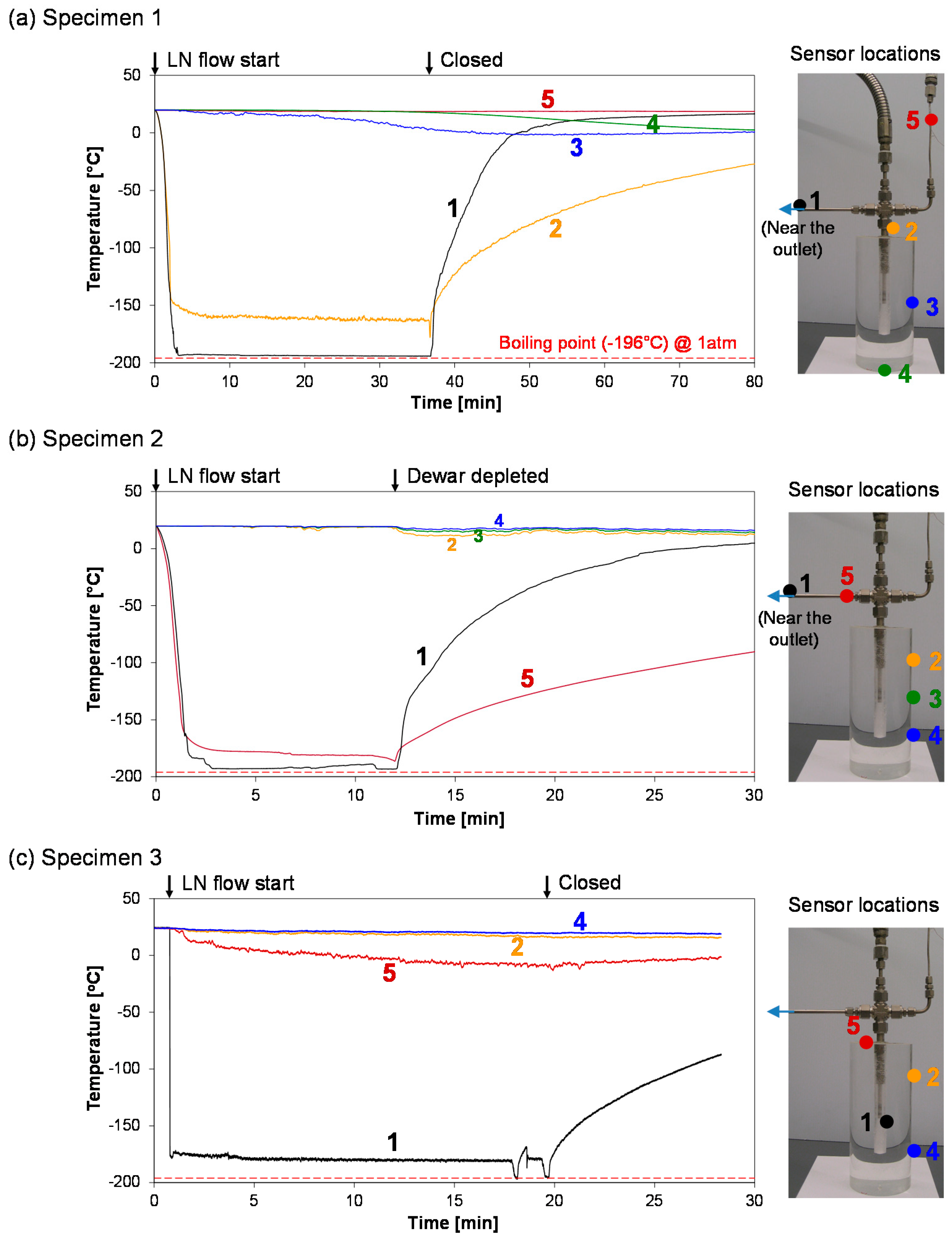
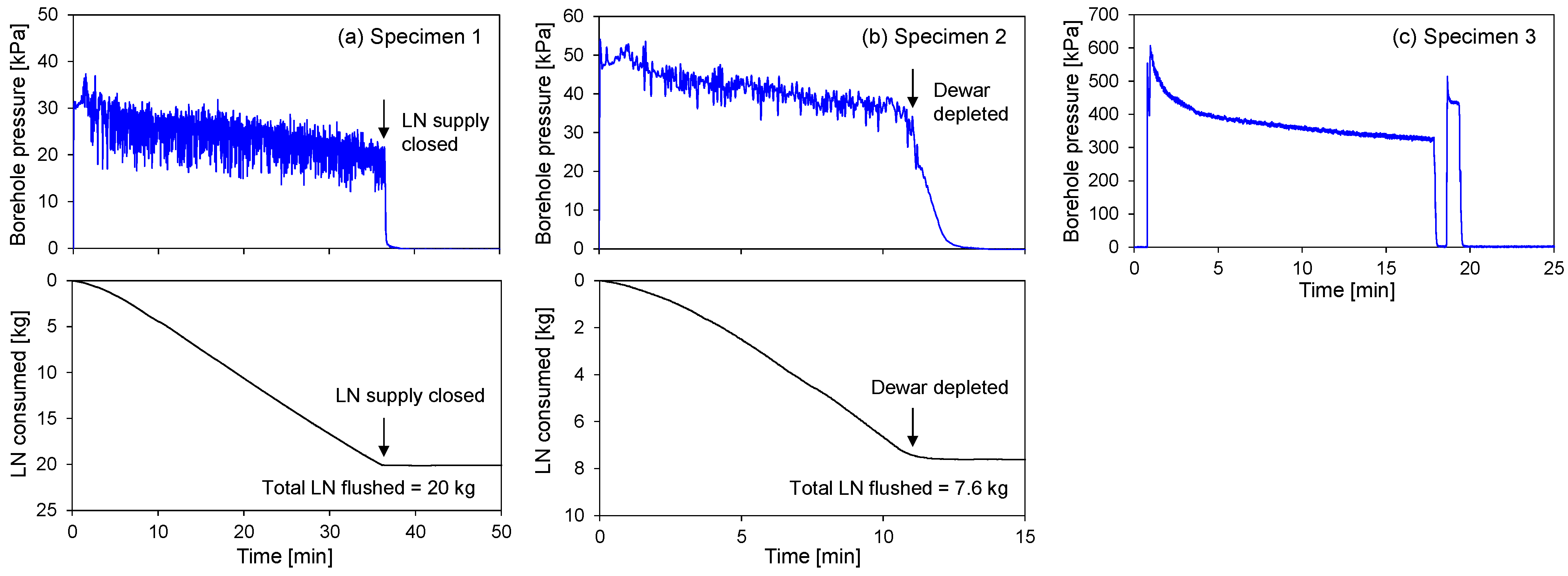
3.1. Temperature, Pressure, and LN Usage

The borehole temperatures of the specimens dropped rapidly with the introduction of LN and reached the boiling point of nitrogen within five minutes in this laboratory setup. The cooling rate was higher at the high flow pressure (1.5 °C/sec for Specimen 1, 2 °C/sec for Specimen 2, and 270 °C/sec for Specimen 3) (Figure 3); a higher mass flow pressure/rate allows better thermal exchange and more depressed thickness of contact film boiling (the Leidenfrost effect), which facilitate thermal conduction. A higher cooling rate is favorable for thermal shock because it creates high local thermal gradients.
The temperature at the outer side surfaces remained high, above 0 °C, and also depends on their proximity to the cracks resulting from the entrance of LN into the cracks (as will be shown in Section 3.6). During the flows, ΔT between the borehole surface and the outer surface remained at or above 200 K, creating an average thermal gradient between the borehole and the outer surfaces of about 46.0 K/cm.
Under the high-pressure injection, the terminal temperature on the borehole wall was maintained between −175 °C and −180 °C, higher than −196 °C, due to the pressure-dependent nitrogen phase boundary and boiling point (Figure 3c). Location #5 in Specimen 1 maintained almost constant room temperature because of no flow in the tubing, allowing the safe use of a regular pressure transducer. Location #5 at the top of Specimen 3 showed lower temperature than other external surfaces because of cold gas nitrogen leaking from the above fitting. At the end of the tests, temperatures dropped by a small amount (e.g., TC#2 of Specimen 1, TC#1 and 5 of Specimen 2, and TC#1 of Specimen 3), caused by the pressure drop in the borehole (Figure 3).
The dewar lever was opened fully during the release of LN without an intermediate closure. The experiment for Specimen 2 was terminated by the depletion of the LN tank. Borehole pressure was mainly determined by the internal pressure of the dewar. Pressure measured at the borehole fell in the range of 20–30 kPa for Specimen 1 and 35–50 kPa for Specimen 2, which was sustained by pressure in the dewar tank (Figure 4). A larger dewar that maintained a higher internal pressure applied greater borehole pressure in the Specimen 3 test. Time plots of borehole pressure show that the borehole pressures were initially higher and then decreased slightly over time because as the flow paths (tubes, rock, and borehole) cool, the reduced vaporization of LN and contraction of already-vaporized gas nitrogen cause the pressure to decrease and nitrogen consumption to increase (Figure 4).
The time plots of LN consumption are slightly curved (Figure 4). Initially, the LN consumption rate was lower, but it increased over time before reaching a constant rate. This is because more vaporization occurred in the early stages because of warm flow paths and, as the system cooled over time, the consumption rate increased and the slope became steeper. Although a substantial amount of LN (20 kg) flowed in the Specimen 1 test, most of the fractures occurred at an early stage (within 15 min). When the Specimen 2 test was terminated at 11 min, the amount of nitrogen that had flowed was only 7.6 kg because of the depleted dewar. The ending transition for Specimen 2 for both LN consumption and borehole pressure was smooth when the dewar became depleted and the flow ended (Figure 4b).
Flow characteristics inside the borehole were observed. Upon the start of the flow, nitrogen inside the borehole flowed as a gas for about 1 ~ 2 min, then as a gas mixed with liquid droplets, and finally as a more continuous liquid phase with a significant amount of gas patches remaining in the mix.

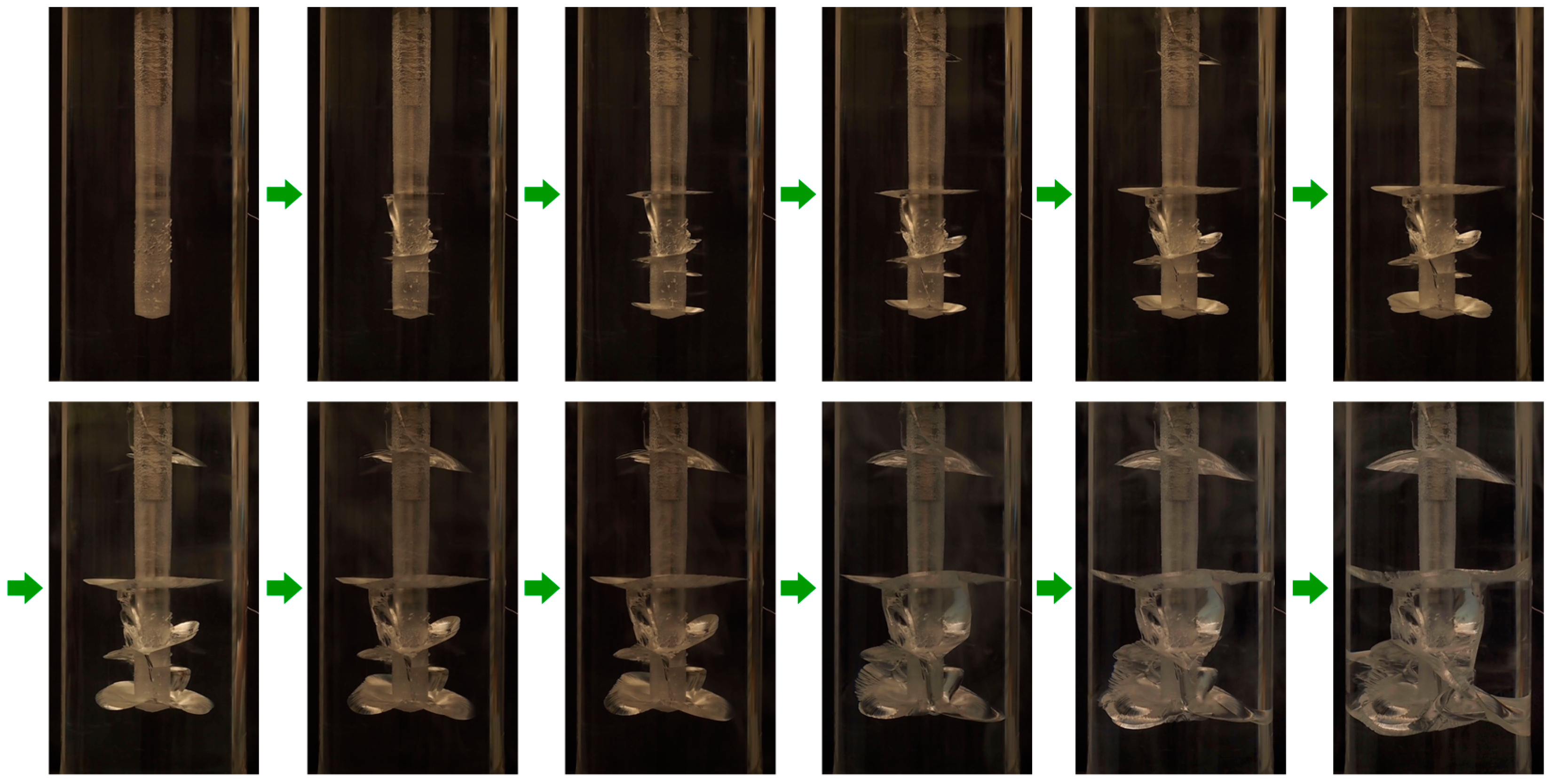
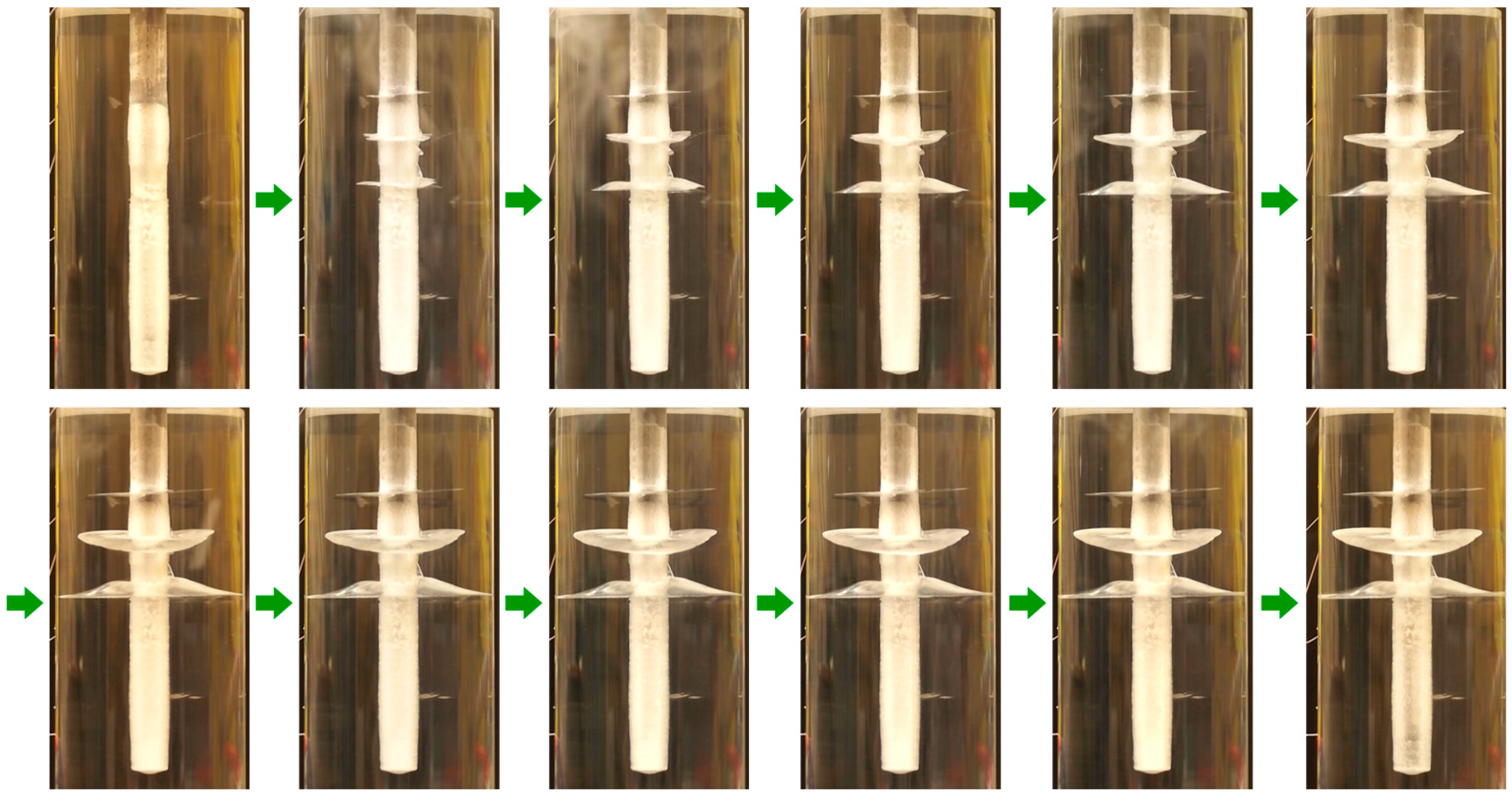
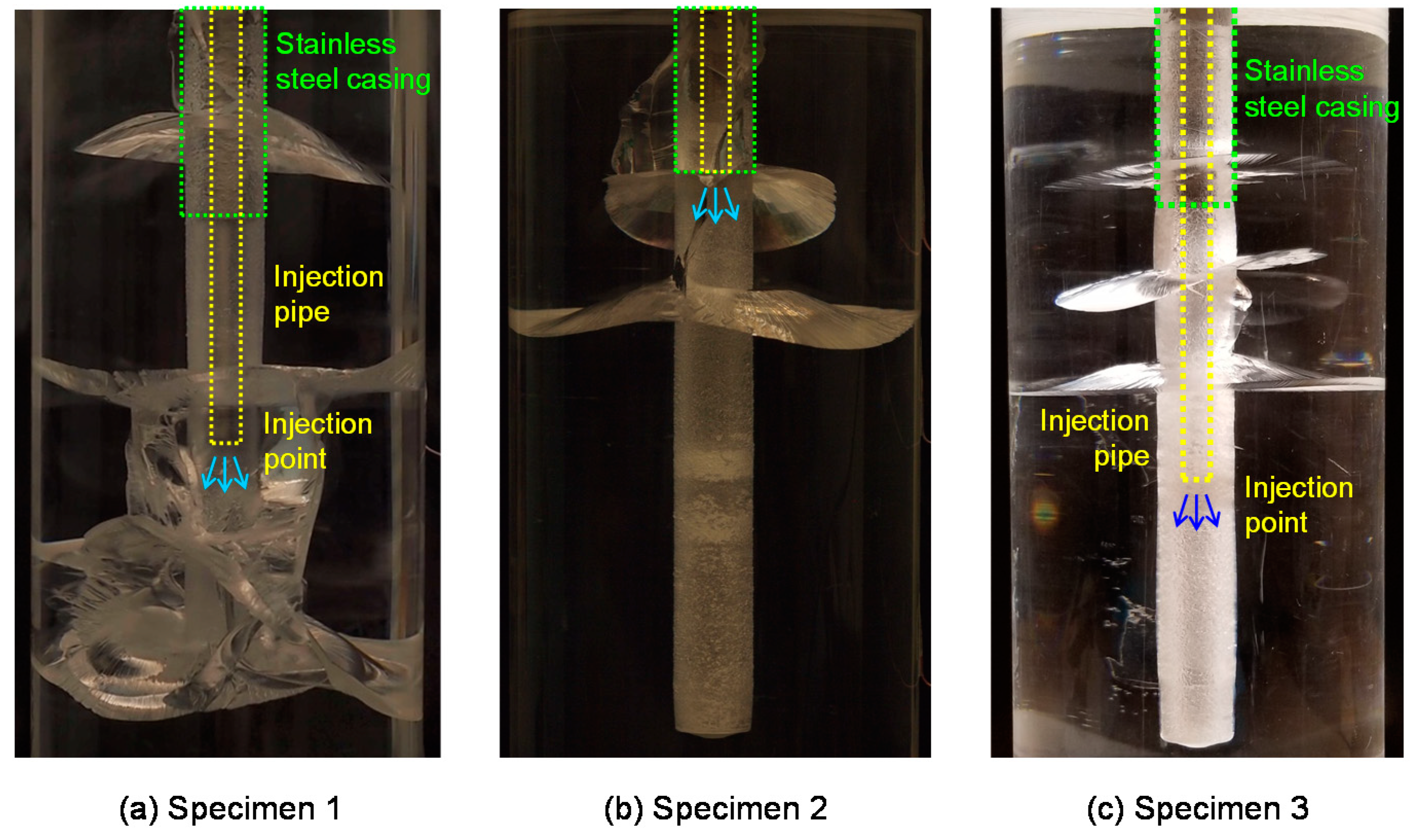
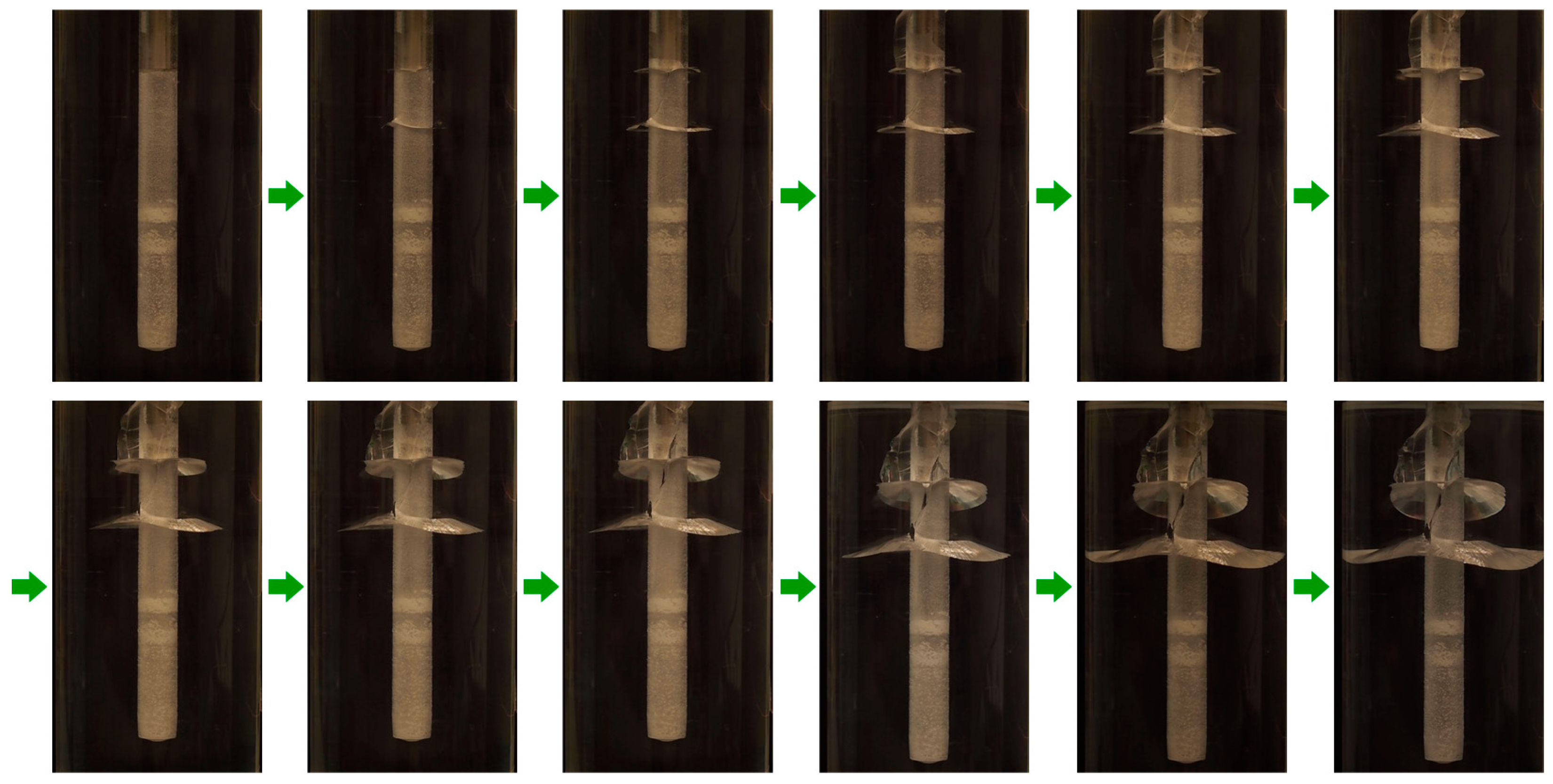
3.2. Fracture Propagation

Rapid cooling induces large tensile stresses at the wellbore surface. If the stress equals the tensile strength of a specimen, the specimen cracks. Changes in the tangential tensile stress component induced by temperature changes on the wellbore wall are estimated by Equation (1) [40,41].
σ m a x Δ T = E 1 ν α · Δ T ,
where ΔT is the temperature difference, α is the coefficient of linear thermal expansion (K−1), E is the static Young’s modulus (GPa), and ν is the Poisson’s ratio. With the specimen properties in Table 1 (E = 2.85 GPa, α = 70 × 10−6/K, and ν = 0.38) and ΔT = 210 °C, σ m a x Δ T is calculated as 67 MPa, which is close to the tensile strengths of 55–76 MPa. Thus, cracks will initiate at the borehole and propagate into the specimen as LN continuously flows.
For all cases, fractures started orthogonally from the borehole surfaces. Fracture propagation was faster in earlier stages. As fractures propagated outward and approached the outer surfaces, the propagation rate became slower because more areas needed to be covered as fractures propagated outward and because local thermal gradients and distances to unstressed outer surfaces decreased.
It was observed that fracture growth was jumpy, characterized by abrupt starts and stops, especially in the early stages. The increased material’s brittleness at cryogenic temperature could be attributed to the jumpiness. As the fracture propagated outward in the later stages, the increments of jumps became smaller, so the propagation appeared to be more continuous. During the experiments, audible sounds were emitted when major fractures opened, hinting at the brittleness of materials.
In general, two patterns in crack development were observed: horizontal/radial fractures and vertical fractures that tended to form between the horizontal fractures. The horizontal/radial fractures constituted the dominant pattern of crack morphology. An explanation for this is that as the specimen was cylindrical with a borehole height greater than the borehole circumference, the thermal contractions became more pronounced in the longitudinal direction, creating horizontal fractures. The horizontal fractures propagated to roughly equal distances from the boreholes in all horizontal directions within the plane. In all cases, the horizontal fractures emerged slightly earlier than the vertical fractures.
Fractures were generated in the vertical direction due to the circumferential thermal contraction, in lesser magnitudes compared to the horizontal fractures. Following the initiation of the horizontal fractures, vertical cracks initiated from and/or formed between the horizontal fractures and bridged them. It appears as if starting from a pre-existing defect (i.e., a horizontal fracture) and propagating toward another defect was energy efficient (Figure 5, Figure 6 and Figure 7). Because of the smaller circumference, only one major vertical fracture initiated from the open borehole, compared to up to three horizontal fractures.
The average speeds of horizontal fracture propagation were quantified from the middle 50–60% portion of propagation using the time lapse photos. The average speeds of fracture propagation were 0.41 cm/min for Specimen 1, 0.40 cm/min for Specimen 2, and 0.51 cm/min for Specimen 3. While the fracture in Specimen 3 grew the fastest, the Specimen 3 test had a higher flow pressure than the others. For the initial crack to emerge, Specimen 3 took only 4 s after initial flow while others took 20–30 s (the initial flow took place mainly during the cryogenic gas phase). The fracture speed of horizontal fractures was significantly faster than that of vertical fractures. As a fracture propagated radially, the fracture propagation rate tended to decrease.
Unlike in the other tests, in the Specimen 2 test, only one major horizontal/radial fracture was created in the open hole (versus three in the other tests) (Figure 6), the cause of which is unclear. However, the difference between the test conditions of Specimen 2 and the others was the shorter stimulation time of Specimen 2 (11 min vs. 36 min of Specimen 1 test); thus, a smaller amount of LN flowed (7.6 kg vs. 20 kg in Specimen 1 test), which could have led to an insufficient accumulation of thermal stress to generate additional fractures. The higher location of the fracture may have been related to the high location of the inlet port (Figure 2b).

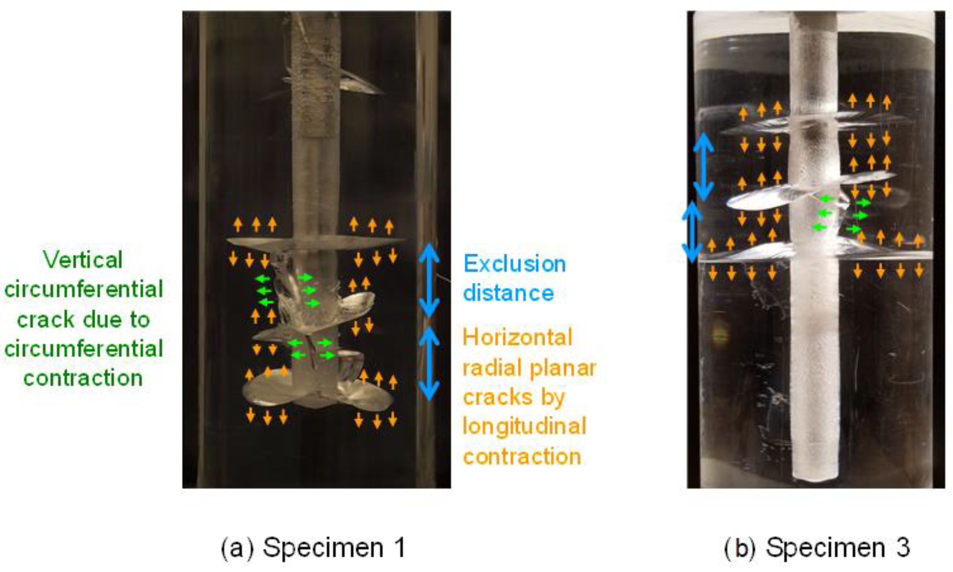
3.3. Exclusion Distance

Horizontal fractures were spaced at a certain length, that is, an “exclusion distance.” An exclusion distance exists because major cracks cannot form closer than a certain length because of the limited amount of thermal contraction (Figure 8). Propagation is focused to major fractures, rather than promoting in-between fractures. For example, photos 2–3 in Figure 5 display a small horizontal fracture visible on the right between the middle and bottom fractures. It stops growing at some point while neighboring fractures continue to grow. The spacing (i.e., exclusion distances) between horizontal fractures in open-hole areas measured 3 cm in Specimen 1 and 2.5 cm in Specimen 3 (Figure 8). The exclusion distance, or crack spacing pattern, has also appeared and been modeled in thermal cracking in simple two-dimensional media [21,22,23]. As there was only one vertical fracture, the exclusion distance was not manifested for the vertical fractures. Exclusion distance is more obvious in the early stages because fractures at later stages begin to interact in a complex manner.
Many geomechanical/geochemical processes have been observed to show the behavior of exclusion distance as an aspect of their manifestations. For example, in the acidizing of carbonate formation, wormhole competition stops the growth of side branches and determines the final wormhole density [42]. In columnar joint morphology, the cross-sectional area of a column is inversely proportional to the cooling rate [43]. When thermal stress reaches the tensile strength of a shrinking asphalt pavement, regularly spaced thermal cracks form across the width [44].

3.4. Fracture Curvature and Interaction between Fractures

While hydraulically driven fractures are generally straight in uncased boreholes [45], every cryogenic fracture in this study was curved after initiation orthogonal to the surface. A curved thermally induced fracture was also observed around shale boreholes [15]. The curvature patterns, however, were not consistent (Figure 5, Figure 6 and Figure 7). Some fractures curved upward, and others curved downward. Some fractures deflected or their curvatures changed after a certain propagation. In some cases, different curvature trends existed within the same horizontal fracture plane.
The curvatures in this study had some similarities with “caged fractures” around underbalanced wellbores where fractures curl around wellbores within a fracture cage [46,47], within which the principal deviatoric compressional stress follows concentric rings, not the far field stress. Thus, while curvature patterns seem arbitrary, distorted stress fields induced by thermal treatments were presumed to determine fracture curvature.
It appears that with a continuous supply of LN, a fracture continues to grow, but its curvature or tortuosity prevents large penetrations. In our tests, some major fractures reached the outer surfaces even though the fractures were curved, possibly the result of the relatively small distances from the borehole to the outer surface. Larger specimen tests would reveal patterns that could hint to a field scale. In Specimen 3, however, fractures were significantly straighter due to the higher borehole pressure, which reduced the impact of internal thermomechanical heterogeneities and fracture curvature/tortuosity and facilitated straighter and more radial propagation.
Between images 9 and 10 in Figure 5 for Specimen 1, the right portion of the middle horizontal fracture propagated upward and suddenly connected to the top horizontal fracture, and the left portion of the bottom horizontal fracture propagated upward and connected to the middle horizontal fracture. In addition, between photos 6 and 7, a fracture branched from the bottom fracture and connected to the small arrested horizontal fracture located between the middle and bottom fractures. All of these connections between the horizontal fractures occurred instantaneously (<0.03 sec) at different times. This instantaneous fracture merging indicates dynamic and complex thermal stress conditions, driven by seemingly more than longitudinal and circumferential thermal stresses. At the end of the experiment, the exclusion distance became less clear, and the specimen showed a complex fracture skeleton resulting from interaction among the fractures (Figure 5).

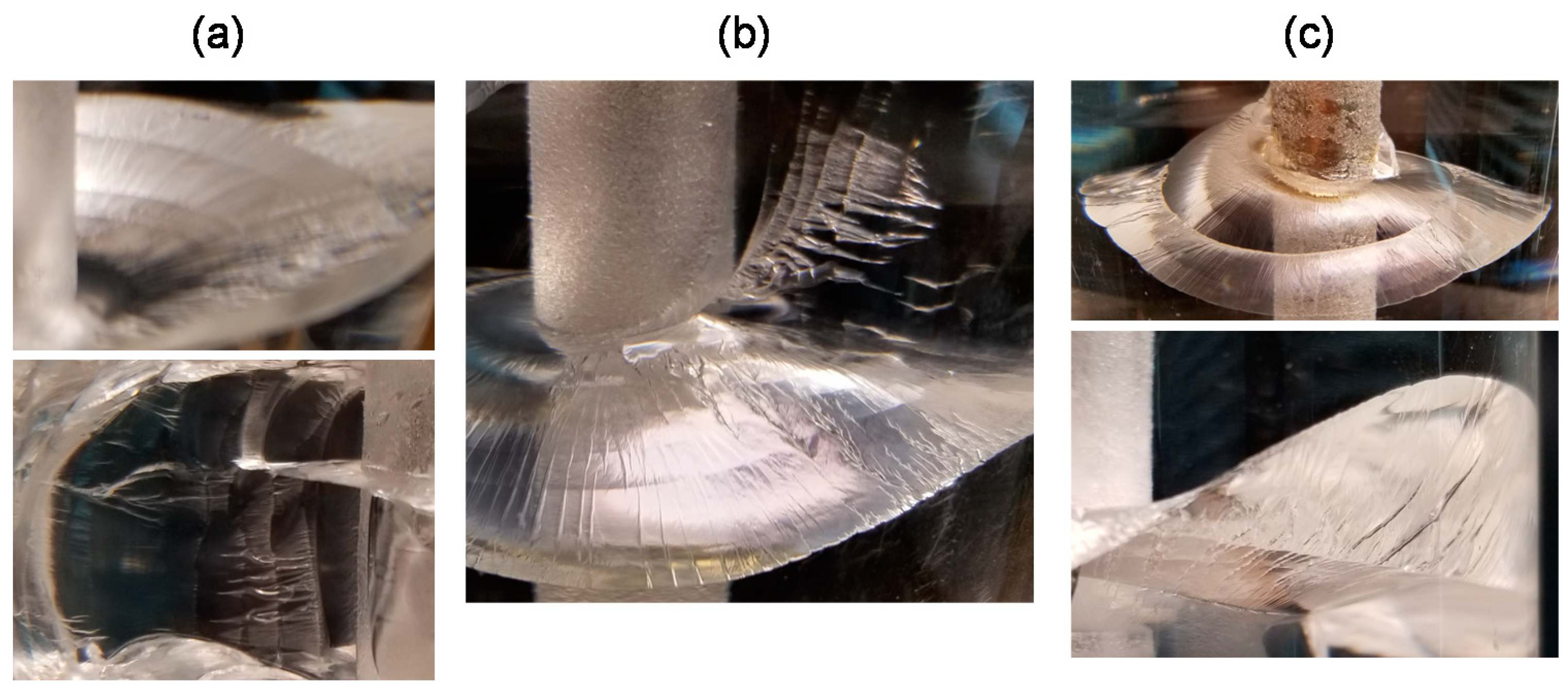
3.5. Striation in Fractures

Another feature, the existence of striation, appeared to be precisely perpendicular to the propagation directions for both horizontal and vertical fractures (Figure 9). Along the many striations, various degrees of changes in the curvature occurred. Along some striations, especially the vertical ones, the curvature changes were not noticeable. Figure 9c illustrates distinct changes in curvatures. Distances between striations in fractures, however, were not equal (Figure 9). In Specimen 3, striation was less distinct and less frequent, which relates to the straighter fractures in Specimen 3, which again relates to the higher borehole pressure applied. In general, striation spacing was smaller near the borehole. Close to the borehole, roughly within 0.5 inch from the wall, striations appeared to be identical to fracture jumps. As the fracture propagated outward, the fracture steps became smaller and more continuous and spacings between the striations became larger. It is postulated that striation could be determined by changing the thermomechanical conditions affected in part by liquid nitrogen in the aperture and by borehole pressure fluctuations, albeit small in this study. In Cha et al. [15], the application of breakdown pressure after cryogenic treatment in shale boreholes created discontinuities in curvature between cryogenic fractures and pressure-induced fractures. It is unknown whether striations in cryogenic fracturing are unique to certain materials; documented observations of cryogenic fracture surfaces in rocks are rare.

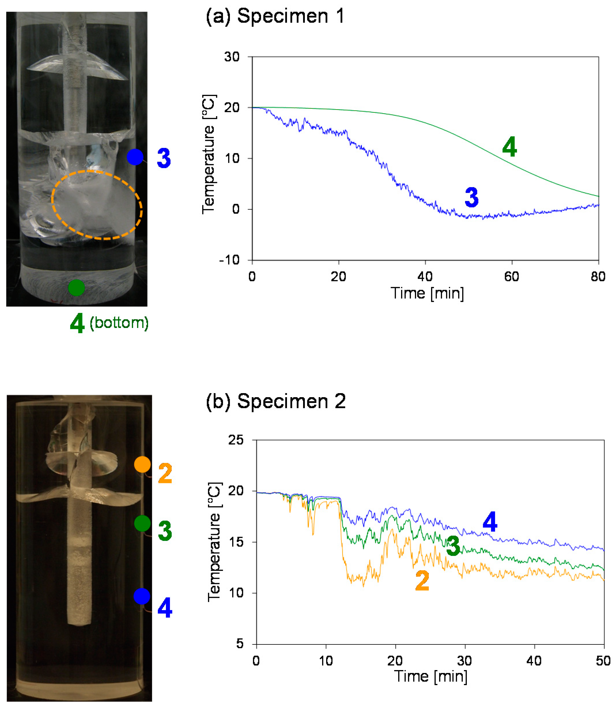
3.6. LN in Crack Aperture on the Propagation of Fracture and Temperature

During LN flow through the boreholes, we visually confirmed that LN moved into and flowed around the fractures created in open holes very close to the tip of thin fractures. The random movement of LN in thin cracks in its liquid state up to ~0.25–0.5 inch from crack tips was facilitated by low viscosity and possibly by low surface tension (viscosity of LN 0.158 cP vs. water 1.002 cP and surface tension of LN 8.85 dynes/cm vs. water 72.8 dynes/cm) (Table 1).
The presence of LN in fracture apertures efficiently cooled fracture surfaces and created a thermal gradient around the fractures, which helped further fracture propagation. In the open borehole, fractures eventually reached the surface at an extended period (Figure 5, Figure 6 and Figure 7). Fractures formed from the casing, yet did not grow as much. Even though they started at about the same time as those in the open hole, the growth of cracks from the casing was limited by a lack of access to LN. Therefore, it follows that a continuous supply of LN into cracks is important for their continuous growth.
The presence of LN in the aperture indicates that the temperature in the aperture was close to the boiling point of LN, and therefore the fractures acted as heat sinks that reduced the surrounding temperature. The temperature on the outside surface was affected by its proximity to the cracks (Figure 10). Since the thermal conductivity of PMMA is low (about 1/6 that of typical shale), the temperature difference between outer surfaces and inside the fractures was large, creating large thermal gradients that facilitated fracture growth.

3.7. Effect of Casing

For all tests, one major horizontal fracture was initiated early in the flow at the stainless steel cased parts of the borehole (Figure 5, Figure 6 and Figure 7 and Figure 11), although they were more distant from inlet ports. The stainless steel casings had a much higher thermal conductivity than PMMA (stainless steel: 16.3 W·m−1·K−1 versus PMMA: 0.185 W·m−1·K−1). Although the fractures in the casing started early, the growth was arrested at some point or slower because of a lack of or a lower rate of LN supply into the fractures caused by the casing, which reduced heat transfer. The epoxy that bonded the casing and the acrylic wall might have changed the stress condition and affected the fracture distribution.

4. Limitations

While PMMA is homogeneous, isotropic, and impermeable in material properties, sedimentary rocks are heterogeneous and have varying degrees of anisotropy and permeability. No confining stress was applied in this study. While detailed descriptions and interpretations of the new observations will benefit analytical and numerical modelers, extension to a field-scale understanding must be aided by further studies using large, confined rock specimens and/or field tests.
PMMA, as a thermoplastic, exhibits brittle behavior below its glass transition temperature of 105 °C and becomes pliable above its transition temperature. While drilling boreholes, if continuous cooling is not applied, the temperature of PMMA can exceed the glass transition temperature and even reach the melting point of 160 °C. We observed that during drilling, borehole surfaces underwent local plastic deformation, creating a texture. Residual stresses may be created near the borehole walls because of the cooling of the hot surface during drilling. When this altered surface with residual stress is rapidly cooled by LN, the development of internal stress can differ from that within a flat, polished, and residual stress-free surface. These complexities can affect crack initiations. To prevent the influence of these uncertainties, the temperature of materials should be kept low by slow drilling and a continuous supply of cooling fluid.
We noticed that fractures were created mainly near the injection point, which may suggest the effect of inlet port location on temperatures, possibly creating a lower temperature near the injection point (Figure 11). However, this interpretation did not apply for the Specimen 3 test; all the fractures were located above the inlet port in Specimen 3 (Figure 11c). This specimen was drilled twice. The first drilling created a hole to a point below the lowest fracture. The second drilling completed the hole, shown in Figure 11c. All fractures in Specimen 3 occurred in the hole created from the first drilling; different levels of residual stress and/or surface textures could exist. An unbiased understanding of the effect of the inlet port requires additional tests using boreholes created with clean, low-temperature drilling, as stated in the above paragraph.

5. Conclusions

We conducted cryogenic fracturing experiments in the boreholes of transparent PMMA specimens so that dynamic cryogenic fracturing processes could be directly observed with time. The study describes in detail the initiation, propagation, morphology, and factors controlling cryogenic fracture processes in a borehole geometry. Salient and unprecedented observations of cryogenic fracture propagation are summarized below.
Cryogenic fracture growth was characterized by abrupt starts and stops owing to the brittleness of the cryogenic PMMA specimens and the accumulated release of tensile stress coupled with fracture propagation and heat transfer. As the fracture propagated outwards, the increments of starts and stops became smaller and its growth turned more continuous. Aided by its low viscosity, LN readily moved into the cracks, which facilitated continuous crack growth.
At their initiation and in early stages, horizontal/radial fractures and vertical fractures were the two defining fracture patterns, driven by longitudinal and hoop stresses, respectively. Horizontal fractures were more dominant than vertical fractures because the borehole length was greater than the borehole circumference, creating more pronounced thermal contractions in the longitudinal direction.
Horizontal fractures tended to be spaced at a certain length, or an exclusion distance. While distinct horizontal/vertical fractures and the exclusion distance manifest themselves at an early stage, fractures later develop into complex shapes because of curvatures and fracture–fracture interactions.
Cryogenic thermal loading induces distinctively curved fractures in homogeneous and fine-grained media. Although all fractures start orthogonally from borehole surfaces, which is favorable in terms of production, the tendency of tortuosity may lead to limited penetration solely by thermal shock. On a positive note, the increase in borehole pressure during LN flow can lessen fracture curvature/tortuosity and facilitate radial propagation. A high flow pressure/rate is also advantageous, for it accelerates the cooling rate and fracture initiation and propagation.
The key features of cryogenic fracturing, that is, multiple set of cracks with spacing, vertical and horizontal fractures, and curvature, differ markedly from those of hydraulic fracturing, in which propagation mainly follows a bi-wing pattern, and is potentially beneficial in that it could increase fracture network density and stimulated reservoir volume even though the penetration depth is likely smaller than that of hydraulic fracturing. Nevertheless, with simultaneous cryogenic and hydraulic loading, significant penetration with multiple sets of fractures may be possible.

Author Contributions

Conceptualization, M.C., X.Y., T.J.K., and Y.-S.W.; methodology, M.C., X.Y., and T.J.K.; formal analysis, M.C. and N.B.A.; investigation, M.C., N.B.A., L.W., and B.Y.; writing—original draft preparation, M.C.; writing—review and editing, X.Y., L.W., J.L.M., T.J.K., and Y.-S.W.; funding acquisition, Y.-S.W., X.Y., J.L.M., T.J.K., and M.C. All authors have read and agreed to the published version of the manuscript.

Funding

This research was funded by the National Energy Technology Laboratory, US Department of Energy, grant number 10122-20. Wang thanks Nazarbayev University for financial support (Funder Project Reference: 021220CRP2022). This research was also supported by Basic Science Research Program through the National Research Foundation of Korea (NRF) funded by the Ministry of Education (2019R1A6A1A10072987).

Institutional Review Board Statement

Not applicable.

Informed Consent Statement

Not applicable.

Data Availability Statement

Not applicable.

Conflicts of Interest

The authors declare no conflict of interest.

References

  1. Huang, Z.; Zhang, S.; Yang, R.; Wu, X.; Li, R.; Zhang, H.; Hung, P. A review of liquid nitrogen fracturing technology. Fuel 2020, 266, 117040. [Google Scholar] [CrossRef]
  2. Wu, X.; Huang, Z.; Li, R.; Zhang, S.; Wen, H.; Huang, P.; Dai, X.; Zhang, C. Investigation on the damage of high-temperature shale subjected to liquid nitrogen cooling. J. Nat. Gas. Sci. Eng. 2018, 57, 284–294. [Google Scholar] [CrossRef]
  3. Han, S.; Cheng, Y.; Gao, Q.; Yan, C.; Han, Z. Experimental study of the effect of liquid nitrogen pretreatment on shale fracability. J. Nat. Gas. Sci. Eng. 2018, 60, 11–23. [Google Scholar] [CrossRef]
  4. Cai, C.; Li, G.; Huang, Z.; Shen, Z.; Tian, S.; Wei, J. Experimental study of the effect of liquid nitrogen cooling on rock pore structure. J. Nat. Gas. Sci. Eng. 2014, 21, 507–517. [Google Scholar] [CrossRef]
  5. Alqatahni, N.B.; Cha, M.; Yao, B.; Yin, X.; Kneafsey, T.J.; Wang, L.; Wu, Y.-S.; Miskimins, J.L. Experimental Investigation of Cryogenic Fracturing of Rock Specimens Under True Triaxial Confining Stresses. In Proceedings of the SPE Europec Featured at 78th EAGE Conference and Exhibition, Vienna, Austria, 20 May 2016; p. 24. Available online: https://onepetro.org/SPEEURO/proceedings-abstract/16EURO/All-16EURO/SPE-180071-MS/186639 (accessed on 30 May 2021).
  6. Elwegaa, K.; Emadi, H. The effect of thermal shocking with nitrogen gas on the porosities, permeabilities, and rock mechanical properties of unconventional reservoirs. Energies 2018, 11, 2131. [Google Scholar] [CrossRef] [Green Version]
  7. Du, M.; Gao, F.; Cai, C.; Su, S.; Wang, Z. Study on the surface crack propagation mechanism of coal and sandstone subjected to cryogenic cooling with liquid nitrogen. J. Nat. Gas. Sci. Eng. 2020, 81, 103436. [Google Scholar] [CrossRef]
  8. Cha, M.; Yin, X.; Kneafsey, T.; Johanson, B.; Alqahtani, N.; Miskimins, J.; Patterson, T.; Wu, Y.-S. Cryogenic fracturing for reservoir stimulation—Laboratory studies. J. Pet. Sci. Eng. 2014, 124, 436–450. [Google Scholar] [CrossRef] [Green Version]
  9. Li, R.; Huang, Z.; Wu, X.; Yan, P.; Dai, X. Cryogenic quenching of rock using liquid nitrogen as a coolant: Investigation of surface effects. Int. J. Heat Mass Transf. 2018, 119, 446–459. [Google Scholar] [CrossRef]
  10. Tang, S.; Wang, J.; Chen, P. Theoretical and numerical studies of cryogenic fracturing induced by thermal shock for reservoir stimulation. Int. J. Rock Mech. Min. Sci. 2020, 125, 104160. [Google Scholar] [CrossRef]
  11. Yang, R.; Chunyang, H.; Huang, Z.; Wen, H.; Li, X.; Huang, P.; Liu, W.; Chen, J. Liquid Nitrogen Fracturing in Boreholes under True Triaxial Stresses: Laboratory Investigation on Fractures Initiation and Morphology. SPE J. 2020, 26, 135–154. [Google Scholar] [CrossRef]
  12. Yao, B.; Wang, L.; Yin, X.; Wu, Y.-S. Numerical modeling of cryogenic fracturing process on laboratory-scale Niobrara shale samples. J. Nat. Gas. Sci. Eng. 2017, 48, 169–177. [Google Scholar] [CrossRef]
  13. Gao, F.; Cai, C.; Yang, Y. Experimental research on rock fracture failure characteristics under liquid nitrogen cooling conditions. Results Phys. 2018, 9, 252–262. [Google Scholar] [CrossRef]
  14. Jiang, L.; Cheng, Y.; Han, Z.; Gao, Q.; Yan, C.; Wang, H.; Fu, L. Effect of liquid nitrogen cooling on the permeability and mechanical characteristics of anisotropic shale. J. Pet. Explor. Prod. Technol. 2019, 9, 111–124. [Google Scholar] [CrossRef] [Green Version]
  15. Cha, M.; Alqahtani, N.B.; Yao, B.; Yin, X.; Kneafsey, T.J.; Wang, L.; Wu, Y.-S.; Miskimins, J.L. Cryogenic Fracturing of Wellbores Under True Triaxial-Confining Stresses: Experimental Investigation. SPE J. 2018, 23, 1271–1289. [Google Scholar] [CrossRef] [Green Version]
  16. Zhang, S.; Huang, Z.; Zhang, H.; Guo, Z.; Wu, X.; Wang, T.; Zhang, C.; Xiong, C. Experimental study of thermal-crack characteristics on hot dry rock impacted by liquid nitrogen jet. Geothermics 2018, 76, 253–260. [Google Scholar] [CrossRef]
  17. Wu, X.; Huang, Z.; Song, H.; Zhang, S.; Cheng, Z.; Li, R.; Wen, H.; Huang, P.; Dai, X. Variations of Physical and Mechanical Properties of Heated Granite After Rapid Cooling with Liquid Nitrogen. Rock Mech. Rock Eng. 2019, 52, 2123–2139. [Google Scholar] [CrossRef]
  18. Wu, X.; Huang, Z.; Cheng, Z.; Zhang, S.; Song, H.; Zhao, X. Effects of cyclic heating and LN2-cooling on the physical and mechanical properties of granite. Appl. Therm. Eng. 2019, 156, 99–110. [Google Scholar] [CrossRef]
  19. Zhang, S.; Huang, Z.; Huang, P.; Wu, X.; Xiong, C.; Zhang, C. Numerical and experimental analysis of hot dry rock fracturing stimulation with high-pressure abrasive liquid nitrogen jet. J. Pet. Sci. Eng. 2018, 163, 156–165. [Google Scholar] [CrossRef]
  20. Zhang, S.; Huang, Z.; Wang, H.; Li, G.; Sepehrnoori, K.; Wu, X.; Hong, C. Experimental study on the rock-breaking characteristics of abrasive liquid nitrogen jet for hot dry rock. J. Pet. Sci. Eng. 2019, 181, 106166. [Google Scholar] [CrossRef]
  21. Bourdin, B.; Marigo, J.-J.; Maurini, C.; Sicsic, P. Morphogenesis and Propagation of Complex Cracks Induced by Thermal Shocks. Phys. Rev. Lett. 2014, 112, 014301. [Google Scholar] [CrossRef] [Green Version]
  22. Jenkins, D.R. Determination of crack spacing and penetration due to shrinkage of a solidifying layer. Int. J. Solids Struct. 2009, 46, 1078–1084. [Google Scholar] [CrossRef] [Green Version]
  23. Jiang, C.P.; Wu, X.F.; Li, J.; Song, F.; Shao, Y.F.; Xu, X.H.; Yan, P. A study of the mechanism of formation and numerical simulations of crack patterns in ceramics subjected to thermal shock. Acta Mater. 2012, 60, 4540–4550. [Google Scholar] [CrossRef] [Green Version]
  24. Yang, R.; Huang, Z.; Shi, Y.; Yang, Z.; Huang, P. Laboratory investigation on cryogenic fracturing of hot dry rock under triaxial-confining stresses. Geothermics 2019, 79, 46–60. [Google Scholar] [CrossRef]
  25. Yang, R.; Hong, C.; Huang, Z.; Yang, Z.; Huang, P. An Experimental Investigation of Cyclic Cryogenic Fracturing in Coalbed Methane Reservoirs. In Proceedings of the 53rd U.S. Rock Mechanics/Geomechanics Symposium, New York, NY, USA, 28 August 2019; p. 8. Available online: https://onepetro.org/ARMAUSRMS/proceedings-abstract/ARMA19/All-ARMA19/ARMA-2019-1710/124954 (accessed on 30 May 2021).
  26. Zhang, H.; Huang, Z.; Zhang, S.; Yang, Z.; McLennan, J.D. Improving heat extraction performance of an enhanced geothermal system utilizing cryogenic fracturing. Geothermics 2020, 85, 101816. [Google Scholar] [CrossRef]
  27. de Borst, K.; Tan, C.P.; Mat Piah, M.F.; Groenenboom, J. First-Time Insights into Hydraulic Fracturing of Unconsolidated Sands from Novel Laboratory Experiments with in-situ CT-Scanning. In Proceedings of the International Petroleum Technology Conference, 23 March–1 April 2021. [Google Scholar]
  28. Huang, P.; Huang, Z.; Yang, Z.; Wu, X.; Li, R.; Zhang, S. An innovative experimental equipment for liquid nitrogen fracturing. Rev. Sci. Instrum. 2019, 90, 036104. [Google Scholar] [CrossRef] [PubMed]
  29. Qin, L.; Zhai, C.; Liu, S.; Xu, J. Mechanical behavior and fracture spatial propagation of coal injected with liquid nitrogen under triaxial stress applied for coalbed methane recovery. Eng. Geol. 2018, 233, 1–10. [Google Scholar] [CrossRef]
  30. Cha, M.; Alqahtani, N.B.; Yin, X.; Kneafsey, T.J.; Yao, B.; Wu, Y.-S. Laboratory system for studying cryogenic thermal rock fracturing for well stimulation. J. Pet. Sci. Eng. 2017, 156, 780–789. [Google Scholar] [CrossRef] [Green Version]
  31. Gan, Q.; Elsworth, D.; Alpern, J.S.; Marone, C.; Connolly, P. Breakdown pressures due to infiltration and exclusion in finite length boreholes. J. Pet. Sci. Eng. 2015, 127, 329–337. [Google Scholar] [CrossRef]
  32. Khadraoui, S.; Hachemi, M.; Allal, A.; Rabiei, M.; Arabi, A.; Khodja, M.; Lebouachera, S.E.I.; Drouiche, N. Numerical and experimental investigation of hydraulic fracture using the synthesized PMMA. Polym. Bull. 2020, 78, 3803–3820. [Google Scholar] [CrossRef]
  33. Alpern, J.; Marone, C.; Elsworth, D.; Belmonte, A.; Connelly, P. Exploring the Physicochemical Processes That Govern Hydraulic Fracture Through Laboratory Experiments. In Proceedings of the 46th U.S. Rock Mechanics/Geomechanics Symposium, Chicago, IL, USA, 1 January 2012; p. 6. Available online: https://onepetro.org/ARMAUSRMS/proceedings-abstract/ARMA12/All-ARMA12/ARMA-2012-678/120896 (accessed on 30 May 2021).
  34. Yu, P.; Yao, X.; Tan, S.; Han, Q. A Macro-Damaged Viscoelastoplastic Model for Thermomechanical and Rate-Dependent Behavior of Glassy Polymers. Macromol. Mater. Eng. 2016, 301, 469–485. [Google Scholar] [CrossRef]
  35. Richeton, J.; Ahzi, S.; Vecchio, K.S.; Jiang, F.C.; Adharapurapu, R.R. Influence of temperature and strain rate on the mechanical behavior of three amorphous polymers: Characterization and modeling of the compressive yield stress. Int. J. Solids Struct. 2006, 43, 2318–2335. [Google Scholar] [CrossRef] [Green Version]
  36. Abdel-Wahab, A.A.; Ataya, S.; Silberschmidt, V.V. Temperature-dependent mechanical behaviour of PMMA: Experimental analysis and modelling. Polym. Test. 2017, 58, 86–95. [Google Scholar] [CrossRef] [Green Version]
  37. Bilotti, E.; Fenwick, O.; Schroeder, B.C.; Baxendale, M.; Taroni-Junior, P.; Degousée, T.; Liu, Z. 6.14 Organic Thermoelectric Composites Materials. In Comprehensive Composite Materials II; Beaumont, P.W.R., Zweben, C.H., Eds.; Elsevier: Oxford, UK, 2018; pp. 408–430. Available online: https://www.sciencedirect.com/science/article/pii/B9780128035818100244?via%3Dihub (accessed on 30 May 2021).
  38. Esposito, M.; Buontempo, S.; Petriccione, A.; Zarrelli, M.; Breglio, G.; Saccomanno, A.; Szillasi, Z.; Makovec, A.; Cusano, A.; Chiuchiolo, A.; et al. Fiber Bragg Grating sensors to measure the coefficient of thermal expansion of polymers at cryogenic temperatures. Sens. Actuators A Phys. 2013, 189, 195–203. [Google Scholar] [CrossRef]
  39. Finn, T.M. Stratigraphic cross Sections of the Niobrara Interval of the Cody Shale and Associated Rocks in the Wind River Basin, Central Wyoming; U. S. Geological Survey: Reston, VA, USA, 2017; p. 3370.
  40. Zoback, M.D. Reservoir Geomechanics; Cambridge University Press, 2010. Available online: https://books.google.co.kr/books?hl=en&lr=&id=Xx63OaM2JIIC&oi=fnd&pg=PR7&dq=40.%09Zoback,+M.D.+Reservoir+Geomechanics%3B+Cambridge+University+Press:++2010.&ots=yuj9CYZaMT&sig=6YiFUgI6w31g9NgUSG9iIYtWRWQ&redir_esc=y#v=onepage&q=40.%09Zoback%2C%20M.D.%20Reservoir%20Geomechanics%3B%20Cambridge%20University%20Press%3A%20%202010.&f=false (accessed on 30 May 2021).
  41. Tarasovs, S.; Ghassemi, A. Self-similarity and scaling of thermal shock fractures. Phys. Rev. E 2014, 90, 012403. [Google Scholar] [CrossRef] [Green Version]
  42. Buijse, M.A. Understanding wormholing mechanisms can improve acid treatments in carbonate formations. SPE Prod. Facil. 2000, 15, 168–175. [Google Scholar] [CrossRef]
  43. Toramaru, A.; Matsumoto, T. Columnar joint morphology and cooling rate: A starch-water mixture experiment. J. Geophys. Res. Solid Earth 2004, 109, B02205. [Google Scholar] [CrossRef]
  44. Timm, D.; Guzina, B.B.; Voller, V.R. Prediction of thermal crack spacing. Int. J. Solids Struct. 2003, 40, 125–142. [Google Scholar] [CrossRef]
  45. Weijers, L. The Near-Wellbore Geometry of Hydraulic Fractures Initiated from Horizontal and Deviated Wells. Ph.D. Thesis, Delft University of Technology, Delft, The Netherlands, 1995. [Google Scholar]
  46. Weijermars, R.; Wang, J. Stress Reversals near Hydraulically Fractured Wells Explained with Linear Superposition Method (LSM). Energies 2021, 14, 3256. [Google Scholar] [CrossRef]
  47. Weijermars, R. Stress cages and fracture cages in stress trajectory models of wellbores: Implications for pressure management during drilling and hydraulic fracturing. J. Nat. Gas. Sci. Eng. 2016, 36, 986–1003. [Google Scholar] [CrossRef]
Figure 1. Experimental setup for cryogenic stimulation using liquid nitrogen.
Energies 14 05433 g001
Figure 2. Dimensions of the PMMA specimens and the locations of the stainless steel casings and inlet tubes.
Energies 14 05433 g002
Figure 3. Locations of temperature sensors and temperature changes during the liquid nitrogen thermal shock experiments.
Energies 14 05433 g003
Figure 4. Borehole pressure and LN consumption during the tests.
Energies 14 05433 g004
Figure 5. Crack development in Specimen 1. The pictures do not represent all of the crack growth steps.
Energies 14 05433 g005
Figure 6. Crack development in Specimen 2.
Energies 14 05433 g006
Figure 7. Crack development in Specimen 3.
Energies 14 05433 g007
Figure 8. Crack morphology and driving thermal tensile stresses. (a) Specimen 1 after 6 minutes’ flow and (b) Specimen 3 at the end of test.
Energies 14 05433 g008
Figure 9. Striations in the cryogenic fractures in PMMA. Striations in horizontal and vertical fractures in (a) Specimen 1 and (b) Specimen 2. (c) Examples of distinct changes in curvatures at striations in Specimen 1.
Energies 14 05433 g009
Figure 10. Effect of crack propagation on the surface temperature. Local frost due to surface temperature below 0 °C appeared in the circled area of Specimen 1 where a fracture reached the surface.
Energies 14 05433 g010
Figure 11. The locations of casings, inlet ports, and fractures.
Energies 14 05433 g011
Table 1. Properties of PMMA used and liquid nitrogen. The properties of shale, gas nitrogen, and water shown for comparison.
PropertiesPMMA (a)PMMA (low-T) (b)Niobrara Shale (c)
Density (g/cm3)1.18–1.192.39
Unconfined compressive strength (MPa)90–120250 (−40 °C)54.6
Tensile strength (MPa)55–76100–110 (−40 °C)8.48 (Splitting)
Static Young’s modulus (GPa)2.4–3.35.1 (−173 °C)41.4
Poisson’s ratio0.35–0.4-0.27
Specific heat capacity (J/(kg·K))1450450 (−196 °C)990
Thermal conductivity (W/(m·K))0.18–0.190.14 (−196 °C)
Linear thermal expansion coeff. (K−1)(60–80) × 10−626 × 10−6 (−196 °C)11 × 10–6
Liquid Nitrogen (d)Gas Nitrogen (e)Water (e)
Viscosity (cP)0.1581.76 × 10−21.002
Density (g/mL)0.8070.00120.998
Surface tension (dyn/cm)(against air)8.8572.8
Specific heat (kJ/(kg∙K))2.041.044.18
Thermal conductivity (W/(m∙K))0.1400.0250.591
(a) At normal temperature and pressure (20 °C and 1 atm) from the manufacturer. (b) At low temperatures [34,35,37,38] (Evonik.com). (c) At normal temperature and pressure (20 °C and 1 atm); measured by the authors [15]. (d) At −196 °C (77 K) and 1 atm. (e) At normal temperature and pressure (20 °C and 1 atm).
Publisher’s Note: MDPI stays neutral with regard to jurisdictional claims in published maps and institutional affiliations.

