Article

Modular Multilevel Converter for Low-Voltage Ride-Through Support in AC Networks

by
Victor Ramon França Bezerra de Souza
1,*,
Luciano Sales Barros
2 and
Flavio Bezerra Costa
1
1
Graduate Program in Electrical and Computer Engineering, Federal University of Rio Grande do Norte, Natal 59064-720, Brazil
2
Computer System Department, Federal University of Paraíba, Coronel João Pessoa 58051-900, Brazil
*
Author to whom correspondence should be addressed.
Energies 2021, 14(17), 5314; https://doi.org/10.3390/en14175314
Submission received: 7 July 2021 / Revised: 29 July 2021 / Accepted: 5 August 2021 / Published: 27 August 2021

Abstract

:
New grid-connected systems have imposed additional requirements regarding reliability, power quality, high levels of power processing capacity, and fault support, where power converters have a crucial role in fulfilling these requirements. Overcoming one of these challenges, this paper proposes a new alternative application to improve the low-voltage ride-through (LVRT) support based on the arm impedance employment of the modular multilevel converter (MMC) by attenuating the fault impacts, avoiding overcurrents and overvoltages. This proposal does not require additional hardware or control loops for LVRT support, only using PI controllers. This paper evaluates symmetrical and asymmetrical grid fault impacts on the converter DC side of four converter topologies: two-level voltage source converter topology (2L-VSC), neutral point clamped (NPC), MMC, and 2L-VSC equipped with a DC-chopper, employing the same control structure for the four topologies, highlighting that the MMC contributed better to LVRT improvement under severe grid conditions.

1. Introduction

The widespread penetration of grid-connected systems has provided high stability to the electrical grid, avoiding eventual load disconnections and unnecessary activation of protection systems [1]. Due to the manufacturing development of power electronic devices, converters achieved profound changes in their structures and control techniques, fulfilling several applications, among them LVRT support [2,3], which has made feasible the high penetration of grid-connected systems.
Major solutions adopted to provide enhanced support under LVRT conditions are based on physical devices such as protection relays, fuses, fault current limiters (FCLs), DC choppers, synchronous static compensators (STATCOMs), dynamic voltage restorers (DVRs), as well as modifications in the control loops [4,5]. Thus, in symmetrical and asymmetrical fault scenarios, these systems must have large fault support to mitigate or suppress overcurrents and overvoltages that may exceed the technical limits of devices, besides leading to a loss of control and stability [6].
Among traditional solutions for improving fault support, specific features of power converters can improve the system robustness through redundant stages, bringing blocking voltage capacity and supporting a high sudden current change di/dt rate. These characteristics make the multilevel converters an attractive solution [7]. The major multilevel converter topologies used at the industrial scale are: NPC [8], flying capacitors (FCs) [9], and cascaded H-bridges (CHBs) [10]. From a structural perspective, NPC is composed of clamping diodes to synthesize output voltage levels; the FC uses capacitors instead diodes; the CHB is composed of series-connected H-bridge cells with independent voltage sources. In the last ten years, with the evolution of CHBs, the MMC has become a promising topology without the drawbacks of clamping diodes, flying capacitors, or independent voltage sources. In addition, its modular structure with easy expansiveness is suitable for high-power applications, such as HVDC systems, wind, and photovoltaic power conversion systems [11,12].
Low-voltage ride-through support under symmetrical and asymmetrical faults was discussed in [13]. A fourth leg is added to the three-phase 3L-NPC based on the flying capacitor, providing a fixed neutral voltage under normal operation and replacing the phase under fault condition by the fourth leg. In [14], a resilient framework for the MMC was proposed for voltage sag recovery against internal and external faults employing circulating arm currents and the capacitor voltage supervision algorithm with a modular multilevel capacitor-clamped DC/DC converter (MMCCC) inserted in each arm of the MMC. In [15], a positive/negative injection sequence droop control for microgrids was proposed, eliminating additional hardware use. The coordinated control employs a droop control with a virtual impedance loop and the positive/negative sequence droop scheme to coordinate power injection under grid faults.
In [16], a similar approach was presented by imposing a current injection limit during the fault, avoiding overcurrents and providing active power and reactive current injection without exceeding the maximum current peak of the grid-connected converter. In [17], a hybrid control-hardware strategy with a surplus active power energy storage scheme was proposed in the turbine generator mechanical system in a permanent magnet synchronous generator (PMSG) using a back-to-back NPC with a DC chopper, providing constant voltage under DC bus limits and avoiding the DC chopper activation in some cases. In [18], a DC bus adaptive control for a two-stage inverter in a photovoltaic system was proposed. The scheme controls the DC bus voltage to follow the grid voltage change, reducing high-frequency harmonics and providing an adequate DC bus voltage level under an LVRT.
The hardware-based strategies in [13,14] require the converter’s structural modification, increasing the complexity of PWM signals and current and voltage control loops. Conversely, References [15,16] proposed ancillary service support based on coordinated control, a well-known solution with the drawback of control loop modifications. On the other hand, References [17,18] dealt with DC bus overvoltage using excess power dissipation and adaptive control, respectively. These last approaches also involve control reference modifications, being strongly dependent on the system parameters and the type of fault and requiring an excellent dynamic response from the controllers. Table 1 summarizes the aforementioned hardware- and control-based techniques for LVRT support.
This paper aims to propose a new alternative application using the MMC for LVRT support improvement to overcome the hardware- and control-based strategies. Unlike the aforementioned state-of-the-art solutions, no additional hardware or control loop modification is required because the MMC arm impedance can use its fault-damping capability, reducing the overcurrents and overvoltages, besides maintaining controllability and protecting the power converter. Table 2 presents the major contributions of this paper’s proposal.
Moreover, this standalone solution disregards the protection and controller response time, acting instantaneously under LVRT. This paper evaluated the performance of four-converter topologies under symmetrical and asymmetrical faults: 3L-MMC, 2L-VSC, 3L-NPC, and 2L-VSC equipped with a DC chopper.

2. Description of Converter Topologies

Figure 1 depicts the three-phase converter topologies 2L-VSC, 3L-NPC, and 3L-MMC implemented in this paper. A fourth configuration, 2L-VSC, equipped with a DC chopper was also implemented. The 2L-VSC is composed of six switches operating in a complementary fashion, synthesizing two utput pole voltage levels: V b u s and zero, for V A O , V B O , and V C O . However, the synthesized phase voltage levels V A N , V B N , and V C N are: 2 V b u s 3 , V b u s 3 , 0, V b u s 3 , and 2 V b u s 3 [19]. The DC chopper used in the DC bus is described in this diagram, which is composed of a drive switch with a series-connected resistor. The chopper is activated under a grid fault condition when the DC bus overvoltage trigger level is reached, dissipating the surplus energy on the resistor [4]. In this paper, the DC chopper activation criterion adopted was 5% over the rated DC bus voltage.
The 3L-NPC topology is composed of four switches per phase, where S 1 and S 2 have their respective complementary switches S 1 ¯ and S 2 ¯ . Besides, the clamping diodes are connected to the DC bus midpoint, fixing the synthesized converter output voltage levels [8,20]. In this case, three pole voltage levels were synthesized: 0, V b u s 2 , and V b u s , while the phase voltages assumed nine voltage levels: 4 V b u s 6 , 3 V b u s 6 , 2 V b u s 6 , V b u s 6 , 0, V b u s 6 , 2 V b u s 6 , 3 V b u s 6 , and 4 V b u s 6 .
The 3L-MMC topology is composed of series-connected half-bridge submodules, where each submodule has two switches ( S 1 and S 2 ) and one capacitor C S M . In addition, each arm has a series R-L ( R a r m and L a r m ) impedance equally distributed among the converter phases [11,12]. Table 3 summarizes the main differences between the three presented topologies.
The synthesized voltage levels for the 3L-MMC are three pole voltage levels and nine phase voltage levels, such as in the 3L-NPC. According to the state of the MMC submodule switches, the capacitor is inserted or bypassed. Thus, the voltage of each submodule V S M that synthesizes the output voltage levels can be described by a switching function as follows:
  • If S 1 = 1 and S 2 = 0, V S M = V c a p ;
  • If S 1 = 0 and S 2 = 1, V S M = 0;
  • Else V S M = 0.
The average capacitor voltage of each submodule is given by:
V c a p = V b u s N S M ,
where N S M is the number of submodules per arm in which the number of output voltage levels is given by ( N S M + 1 ). Each arm in the MMC is equivalent to a controlled voltage source V a r m with the instantaneous voltage amplitude given by:
V a r m = S M a c t i v e V b u s N ,
where S M a c t i v e and N are the number of active submodules and the number of converter levels, respectively. Considering that V S M is the submodule voltage, V a r m and therefore the MMC voltage levels are given as a function of the sum of the submodule voltages and the voltage drop across R a r m and L a r m ; thus:
V a r m = n = 0 S M a c t i v e ( V S M ) + L a r m d i a r m d t + R a r m i a r m .
The sinusoidal pulse width modulation (SPWM) technique based on triangular carriers compared to the three-phase reference voltages generates the trigger signals for the 2L-VSC switches [21]. The topologies 3L-NPC and 3L-MMC use the phase disposition pulse width modulation (PDPWM) technique, which is based on triangular level-shifted carriers, where the number of carriers N t r i is given by ( N 1 ) [22]. The MMC topology requires a voltage classification algorithm for capacitor insertion based on the number of active submodules providing voltage equalization, depicted in Figure 2.

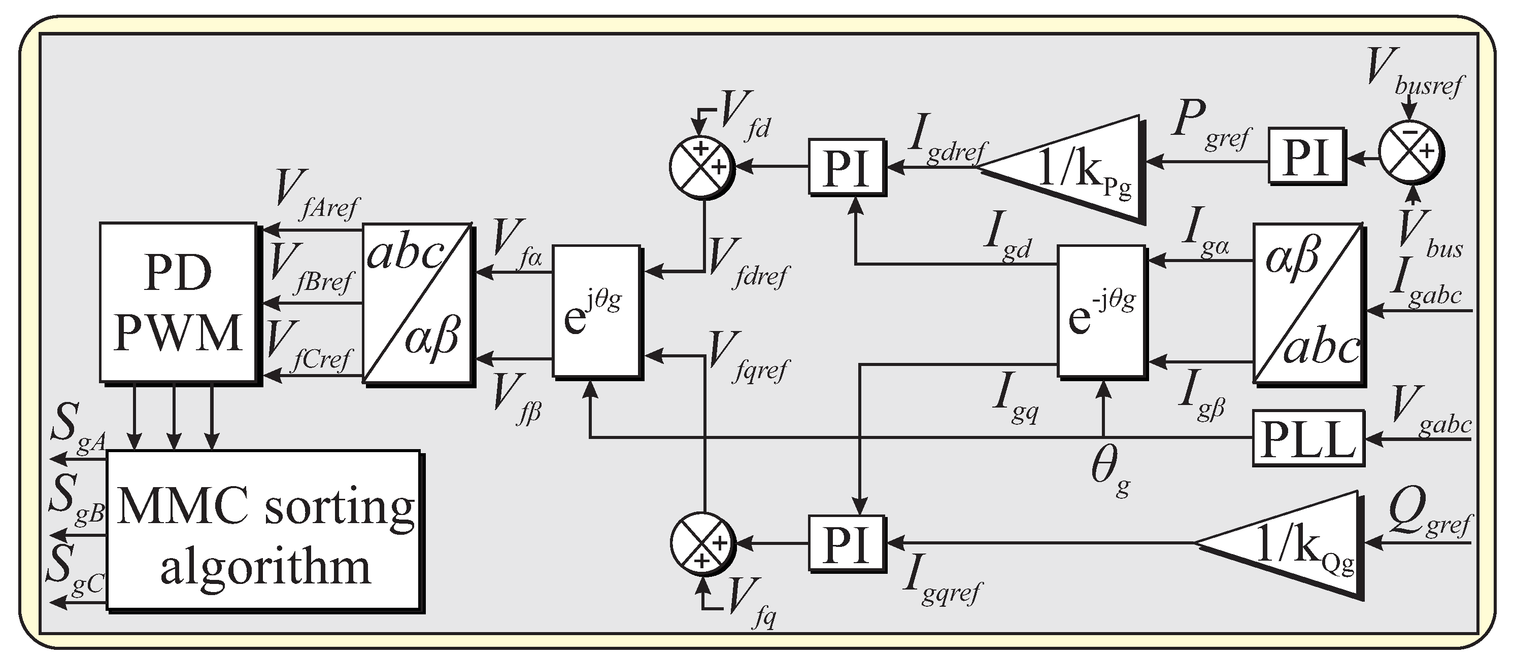
3. The Proposed Application

The proposed application considers the damping characteristic of the MMC circuit. Unlike other topologies, the representative circuit per phase of the MMC can be described by a series RLC circuit, where the capacitance is variable and given by the time-varying active submodules. Thus, the damping is derived from v ( t ) = L d i ( t ) d t and i ( t ) = C d v ( t ) d t , which are the basic L-C voltage–current relations, respectively. In this case, these relations indicate opposition to sudden current and voltage variations since they are state variables that cannot vary instantaneously [4]. In terms of the RLC second-order circuit and considering C S M i n s t as the total active submodule instantaneous capacitance, Equation (2) can be rewritten as:
V a r m = 1 C S M i n s t t 0 i a r m d t + L a r m d i a r m d t + R a r m i a r m .
This means that this characteristic is critical to avoid high levels of overcurrents and overvoltages under LVRT conditions. Thus, the network terminals see the MMC as a dampened circuit [23], as depicted in Figure 3.
In Figure 3, V b u s and i C C are the DC bus voltage and the MMC arm current, respectively, controlled by the control scheme depicted in Figure 4.
The MMC control scheme (Figure 4) is based on vector control in synchronous reference frame d q 0 , in which the DC bus voltage, V b u s , is controlled by an outer PI controller generating the active power reference, P g r e f , by means of I g d r e f . Another controller is responsible for the reactive power, Q g r e f , by means of I g q r e f ; this reference was adopted as zero, which indicates that there is no reactive power delivered to the grid.
On the other hand, the currents measured at the PCC were transformed to the d q 0 reference using the Clarke and Park transforms, thus generating the I g d and I g q that were applied to the inner controllers; these controllers provide the grid reference voltages by means of V f d r e f and V f q r e f , used in the Park inverse transform to generate the trigger signals by means of the PWM. A PLL was used for the grid synchronization, providing the angle, θ g , used in Park direct and inverse transforms.
The PDPWM technique provides the number of active submodules by means of a comparison of the reference voltages, V f A r e f , V f B r e f , and V f C r e f , between two level-shifted triangular carriers in phase with each other. To equalize the MMC submodules capacitor voltages, the voltage balancing algorithm was employed as depicted in Figure 2; the algorithm was based on the MMC upper and lower arms’ current direction, in which the number of active submodules is given by the PDPWM and used in the algorithm to determine which submodule should be inserted or bypassed. If the arm current is positive, the N submodules with the lowest voltages must be activated; conversely, if the arm current is negative, the N submodules with the highest voltages must be activated. Finally, after determining the active submodules, the trigger signals are sent to the converter.
The selection criterion of the L a r m and C S M parameters used in this paper can be obtained based on the procedure presented in [11,24]. R a r m was adopted using typical commercial values based on the resistance per length of the wire used in making the MMC arm reactor; for simplicity, this paper adopted the R a r m , L a r m , and C S M parameters according to Table 4. Furthermore, the selection of L a r m and C S M has different objectives such as to reduce the voltage ripple across the submodules’ capacitors, suppress the MMC circulating current, and the damping of the fault current rise rate in HVDC systems, as discussed in [24,25]. The MMC application in LVRT support additionally allows the arm impedance parameters’ adjustment, submodule capacitance, and the increase of the number of levels, improving the overcurrents’ and overvoltages’ reduction for a wide range of power levels.

4. Performance Assessment

Figure 5 depicts the background of the implemented scenario, composed of a grid-connected converter with a generic distributed generation system represented by a precharged DC bus capacitor C b u s . This system is connected to the three-phase network represented by an infinite bus with a line impedance Z g .
The MMC for LVRT support was demonstrated in scenarios with symmetric and asymmetric faults: single line-to-ground (SLG), double line-to-ground (DLG), line-to-line (LL), and three-phase (LLL) with a 125 ms duration. Table 4 presents the parameters of the implemented system and LVRT scenarios. For the performance assessment, the same control structure was used in the four converter topologies, ensuring a reliable comparison.
Figure 6 depicts the results obtained for the 2L-VSC and 2L-VSC with the DC chopper, 3L-NPC, and 3L-MMC, which are addressed in the remainder of this section.

4.1. 2L-VSC in the LVRT Scenario

The 2L-VSC without the DC chopper presented the following performance (Figure 6):
  • SLG fault: The control maintained V b u s within the reference values during the fault period. However, when the PCC voltage returned to the prefault values, an overvoltage occurred: V b u s reached approximately 637 V, which was an increase of 6.16% compared to the steady-state value, while the DC current ( I C C ) reached approximately 15 A, representing about four-times the steady-state current;
  • DLG fault: V b u s reached a maximum of approximately 641 V, representing an increase of 6.83%, while I C C presented a similar behavior to the LG fault scenario;
  • LL fault: V b u s reached a maximum of approximately 635 V, which was an increase of 5.83% compared to the steady-state value, while I C C reached approximately 9.5 A, representing about 2.53-times the steady-state current;
  • LLL fault: For the worst-case scenario, V b u s reached a maximum of 720 V, representing an overvoltage level of 20%, while I C C reached 30 A, being more than nine-times the steady-state. The obtained results demonstrated that the 2L-VSC has a lower LVRT support, resulting in a higher possibility of damaging several system components during a severe grid fault.
The 2L-VSC with the DC chopper presented the following performance (Figure 6):
  • SLG fault: Around the fault’s initiation, the control maintained V b u s at the reference value. When V P C C reestablished its prefault voltage, an overvoltage 5% lower than without the DC chopper occurred. Conversely, I C C reached a maximum value of approximately 12 A with a reduction of 20% compared to the 2L-VSC without the chopper;
  • DLG fault: V b u s reached a maximum value of 635 V, while I C C reached a peak of 10.2 A, representing a reduction of 9.36% and 7.27% compared to the case without the DC chopper, respectively;
  • LL fault: V b u s reached a maximum value of 637 V, while I C C reached a peak of 10.5 A, representing a V b u s increase of 0.31%, while I C C increased 10.52% compared to the previous case;
  • LLL fault: V b u s reached a maximum of 700 V, while I C C reached a maximum of 30.5 A. There was a reduction of V b u s compared to the previous case of 2.83%. Conversely, I C C obtained an increase of 3.33%.

4.2. 3L-NPC in the LVRT Scenario

The 3L-NPC presented the following performance (Figure 6):
  • SLG fault: Similar to the previous cases, the control maintained V b u s within the reference value, reaching a maximum of 633 V when V P C C started to recover to the prefault condition, while I C C reached a peak of 11 A. The 3L-NPC obtained a performance similar to the 2L-VSC without the DC chopper;
  • DLG fault: The 3L-NPC achieved similar performance to 2L-VSC with the chopper, with V b u s reaching a maximum value of 632 V, while I C C reached a peak of 11 A;
  • LL fault: V b u s reached a maximum value of 615 V, while I C C reached a peak of 9 A;
  • LLL fault: The 3L-NPC obtained superior performance compared to 2L-VSC with and without the chopper, with V b u s reaching a maximum of approximately 675 V and I C C reaching a peak of 28.7 A, representing a reduction of 6.25% and 3.33% compared to the 2L-VSC without the chopper, respectively, as well as 3.57% and 1.03% compared to the 2L-VSC with the chopper, respectively.

4.3. 3L-MMC in LVRT Scenario

The 3L-MMC presented the following performance (Figure 6):
  • SLG fault: The control maintained V b u s within the reference value at the fault occurrence. When V P C C recovered to the prefault voltage levels, V b u s reached a maximum value of 615 V, while I C C reached a peak of 5 A. Compared to the steady-state value, V b u s and I C C increased 2.5% and approximately 1.5-times, respectively. However, the 3L-MMC presented the best performance, reducing by approximately 42.85% the overvoltage level and 50% the overcurrent level compared to the 2L-VSC with and without the DC chopper and the 3L-NPC;
  • DLG fault: V b u s reached a maximum of 617 V, while I C C reached a maximum of 8 A, representing an increase of 2.83- and 2.28-times the steady-state value, respectively;
  • LL fault: V b u s reached a maximum of 612 V, while I C C reached a maximum of 5.2 A, representing a V b u s decrease of 0.48%, while I C C decreased 41.11% compared to the 3L-NPC topology;
  • LLL fault: The 3L-MMC obtained for V b u s a maximum of 625 V and for I C C a peak of 10 A, representing an increase of 4.16% and 2.85-times the steady-state value, respectively. However, the 3L-MMC provided a reduction of the overvoltage and overcurrent level of 4.8-times and 3-times, respectively, compared to the 2L-VSC without the chopper. Regarding the 2L-VSC with the chopper, there was a reduction of four- and three-times V b u s and I C C , respectively, besides three-times for 3L-NPC in both cases.

4.4. Comparison of the 2L-VSC, 3L-NPC, and 3L-MMC under LVRT Scenarios

Based on the obtained results, the use of the DC chopper in the 2L-VSC as a physical protection provided a slight improvement in all fault scenarios. Nevertheless, the support requirement during a voltage sag was effectively achieved using the 3L-MMC, which presented the best performance among all the topologies, reducing the overvoltage and overcurrent levels about 50% and four-times lower than the steady-state values, respectively, considering the worst-case without the DC chopper.
Moreover, even with the chopper activation and the use of the 3L-NPC, no meaningful contribution was verified to improve low-voltage ride-through support. On the other hand, the MMC structure provided the best transient response during the three fault scenarios, indicating that the structure composed of the submodules with capacitor voltage equalization provided considerable robustness and reliability to the grid-connected system, avoiding the harmful effects during a severe network voltage sag in the system components. In addition, based on the DC chopper threshold activation of 5% over the rated DC bus voltage V b u s > 630 V, in any fault scenario, the MMC would not activate the protection. Table 5 presents the performance assessment heat map highlighting the best performance of the MMC in all fault scenarios.

5. Conclusions

This paper presented a new application proposal to improve the low-voltage ride-through in grid-connected systems based on the modular multilevel converter impedance fault current damping capability. Comparisons to the two-level converter with the DC chopper and the neutral point clamped converter employing the same control loops indicated the better performance of modular multilevel converters for symmetrical and asymmetrical faults.
The study also demonstrated that a modular multilevel converter structure can mitigate the activation of physical protection under severe network faults, not only suppressing overvoltages and overcurrents, but also contributing effectively to increasing the robustness and control transient dynamic response, avoiding the hardware requirement or complex control loops’ implementation. In particular, this proposal can be extended to systems with higher low-voltage ride-through susceptibility, effectively contributing to meeting international grid codes, such as: wind energy conversion systems based on doubly fed induction generators, squirrel cage induction generators, and permanent-magnet synchronous generators. Therefore, the modular multilevel converter can be an alternative solution in grid-connected systems for low-voltage ride-through support improvement.

Author Contributions

Conceptualization, V.R.F.B.d.S., L.S.B. and F.B.C.; methodology, V.R.F.B.d.S.; software, V.R.F.B.d.S.; validation, V.R.F.B.d.S., L.S.B. and F.B.C.; formal analysis, V.R.F.B.d.S.; investigation, V.R.F.B.d.S.; resources, V.R.F.B.d.S., L.S.B. and F.B.C.; data curation, V.R.F.B.d.S.; writing—original draft preparation, V.R.F.B.d.S.; writing—review and editing, V.R.F.B.d.S., L.S.B. and F.B.C.; visualization, V.R.F.B.d.S.; supervision, L.S.B. and F.B.C.; project administration, V.R.F.B.d.S., L.S.B. and F.B.C.; funding acquisition, L.S.B. and F.B.C. All authors read and agreed to the published version of the manuscript.

Funding

This research was funded by the National Council for Scientific and Technological (CNPq) and by the Coordination for the Improvement of Higher Education Personnel (CAPES).

Acknowledgments

This work was supported by the National Council for Scientific and Technological (CNPq) and by the Coordination for the Improvement of Higher Education Personnel (CAPES), Brazil.

Conflicts of Interest

The authors declare no conflict of interest.

References

  1. Bollen, M.H.; Hassan, F. Integration of Distributed Generation in the Power System; John Wiley & Sons: Hoboken, NJ, USA, 2011; Volume 80. [Google Scholar]
  2. Infield, D.; Freris, L. Renewable Energy in Power Systems; John Wiley & Sons: Hoboken, NJ, USA, 2020. [Google Scholar]
  3. Abad, G. Power Electronics and Electric Drives for Traction Applications; John Wiley & Sons: Hoboken, NJ, USA, 2016. [Google Scholar]
  4. Abu-Rub, H.; Malinowski, M.; Al-Haddad, K. Power Electronics for Renewable Energy Systems, Transportation and Industrial Applications; John Wiley & Sons: Hoboken, NJ, USA, 2014. [Google Scholar]
  5. Tabatabaei, N.M.; Kabalci, E.; Bizon, N. Microgrid Architectures, Control and Protection Methods; Springer: Berlin/Heidelberg, Germany, 2019. [Google Scholar]
  6. Zhong, Q.C.; Hornik, T. Control of Power Inverters in Renewable Energy and Smart Grid Integration; John Wiley & Sons: Hoboken, NJ, USA, 2012; Volume 97. [Google Scholar]
  7. Sharkh, S.M.; Abu-Sara, M.A.; Orfanoudakis, G.I.; Hussain, B. Power Electronic Converters for Microgrids; John Wiley & Sons: Hoboken, NJ, USA, 2014. [Google Scholar]
  8. Nabae, A.; Takahashi, I.; Akagi, H. A new neutral-point-clamped PWM inverter. IEEE Trans. Ind. Appl. 1981, 17, 518–523. [Google Scholar] [CrossRef]
  9. Meynard, T.; Foch, H. Multi-level choppers for high voltage applications. EPE J. 1992, 2, 45–50. [Google Scholar] [CrossRef]
  10. Mcmurray, W. Fast Response Stepped-Wave Switching Power Converter Circuit, 1971. U.S. Patent 3,581,212, 25 May 1971. [Google Scholar]
  11. Du, S.; Dekka, A.; Wu, B.; Zargari, N. Modular Multilevel Converters: Analysis, Control, and Applications; John Wiley & Sons: Hoboken, NJ, USA, 2017. [Google Scholar]
  12. Lesnicar, A.; Marquardt, R. An innovative modular multilevel converter topology suitable for a wide power range. In Proceedings of the 2003 IEEE Bologna Power Tech Conference Proceedings, Bologna, Italy, 23–26 June 2003; Volume 3. [Google Scholar] [CrossRef]
  13. Ceballos, S.; Pou, J.; Robles, E.; Gabiola, I.; Zaragoza, J.; Villate, J.L.; Boroyevich, D. Three-Level Converter Topologies with Switch Breakdown Fault-Tolerance Capability. IEEE Trans. Ind. Electron. 2008, 55, 982–995. [Google Scholar] [CrossRef]
  14. Ghazanfari, A.; Mohamed, Y.A.I. A Resilient Framework for Fault-Tolerant Operation of Modular Multilevel Converters. IEEE Trans. Ind. Electron. 2016, 63, 2669–2678. [Google Scholar] [CrossRef]
  15. Zhao, X.; Guerrero, J.M.; Savaghebi, M.; Vasquez, J.C.; Wu, X.; Sun, K. Low-Voltage Ride-Through Operation of Power Converters in Grid-Interactive Microgrids by Using Negative-Sequence Droop Control. IEEE Trans. Power Electron. 2017, 32, 3128–3142. [Google Scholar] [CrossRef] [Green Version]
  16. Lee, C.; Hsu, C.; Cheng, P. A Low-Voltage Ride-Through Technique for Grid-Connected Converters of Distributed Energy Resources. IEEE Trans. Ind. Appl. 2011, 47, 1821–1832. [Google Scholar] [CrossRef]
  17. Alepuz, S.; Calle, A.; Busquets-Monge, S.; Kouro, S.; Wu, B. Use of Stored Energy in PMSG Rotor Inertia for Low-Voltage Ride-Through in Back-to-Back NPC Converter-Based Wind Power Systems. IEEE Trans. Ind. Electron. 2013, 60, 1787–1796. [Google Scholar] [CrossRef]
  18. Ding, G.; Gao, F.; Tian, H.; Ma, C.; Chen, M.; He, G.; Liu, Y. Adaptive DC-Link Voltage Control of Two-Stage Photovoltaic Inverter During Low Voltage Ride-Through Operation. IEEE Trans. Power Electron. 2016, 31, 4182–4194. [Google Scholar] [CrossRef]
  19. Yazdani, A.; Iravani, R. Voltage-Sourced Converters in Power Systems: Modeling, Control, and Applications; John Wiley & Sons: Hoboken, NJ, USA, 2010. [Google Scholar]
  20. Vijeh, M.; Rezanejad, M.; Samadaei, E.; Bertilsson, K. A General Review of Multilevel Inverters Based on Main Submodules: Structural Point of View. IEEE Trans. Power Electron. 2019, 34, 9479–9502. [Google Scholar] [CrossRef]
  21. Holmes, D.; Lipo, T.; Lipo, T. Pulse Width Modulation for Power Converters: Principles and Practice; IEEE Press Series on Power Engineering; IEEE Press: Piscataway Township, NJ, USA, 2003. [Google Scholar]
  22. Peddapelli, S. Pulse Width Modulation: Analysis and Performance in Multilevel Inverters; De Gruyter: Berlin, Germany, 2016. [Google Scholar]
  23. Jamshidifar, A.; Jovcic, D. Small-Signal Dynamic DQ Model of Modular Multilevel Converter for System Studies. IEEE Trans. Power Deliv. 2016, 31, 191–199. [Google Scholar] [CrossRef] [Green Version]
  24. Zygmanowski, M.; Grzesik, B.; Nalepa, R. Capacitance and inductance selection of the modular multilevel converter. In Proceedings of the 2013 15th European Conference on Power Electronics and Applications (EPE), Lille, France, 2–6 September 2013; pp. 1–10. [Google Scholar] [CrossRef]
  25. Kang, J.; Kang, D.W.; Lee, J.P.; Yoo, D.W.; Shim, J.W. Design Procedure of MMC-HVDC System: Comprehensive Consideration of Internal and External Dynamics. IEEE Access 2020, 8, 157437–157450. [Google Scholar] [CrossRef]
Figure 1. Three-phase converter topologies: 2L-VSC, 3L-NPC, and 3L-MMC.
Energies 14 05314 g001
Figure 2. MMC capacitor voltage balancing algorithm.
Energies 14 05314 g002
Figure 3. MMC per phase average circuit.
Energies 14 05314 g003
Figure 4. MMC control scheme.
Energies 14 05314 g004
Figure 5. Implemented system background.
Energies 14 05314 g005
Figure 6. Obtained results for the 2L-VSC, 3L-NPC, and 3L-MMC for the SLG, DLG, LL, and LLL faults.
Energies 14 05314 g006
Table 1. Summary of hardware- and control-based LVRT techniques.
ReferenceTechniqueAdvantagesDrawbacks
[13]Fourth leg addition
to 3L-NPC-based
flying capacitor.
Fixed neutral voltage under
normal operation and
phase replacement under LVRT.
Hardware addition;
complex PWM and
control loops.
[14]Multilevel modular
capacitor-clamped DC/DC
converter (MMCCC);
supervisory algorithm.
Postfault restoration
scheme.
Hardware addition;
complex control
algorithm implementation;
high implementation costs.
[15,16]Positive/negative
sequence droop control/
current injection.
Grid voltage support.Complex two-layer
hierarchical control
implementation;
control loop modification.
[17]Surplus active power
energy storage;
DC chopper.
Avoids DC bus overvoltages
under LVRT.
Hardware addition;
control coordination
requirement.
[18]Adaptive DC bus
voltage control.
High-frequency
harmonics reduction;
avoids DC bus overvoltages
under LVRT.
Reference control loop
modification;
strongly dependent
on the system parameters.
Table 2. Summary of the proposed application for LVRT support.
Proposed ApplicationAdvantagesContributions
MMC for
LVRT support.
No additional hardware;
no complex control loops;
avoids DC bus
overvoltages
under LVRT;
avoids overcurrents
under LVRT;
easily expandable
modular structure.
✓ MMC arm impedance
for overcurrent and
overvoltage suppression
under LVRT;
✓ avoids the
protection activation;
✓ supports the
grid connection
under LVRT;
✓ maintains the controllability
of the power converter.
Table 3. Comparative summary between the VSC, NPC, and MMC for any level.
CriterionVSCNPCMMC
Clamping
diodes
0( N 1 )( N 2 )0
Number of
switches
66( N 1 )12( N 1 )
CapacitorsDC bus( N 1 )6( N 1 )+1
Switch
blocking
voltage
V b u s V b u s ( N 1 ) V b u s ( N 1 )
ModularityNoNoYes
Voltage
balancing
NoDC busPer
submodule
RedundancyNoNoYes
Table 4. System parameters.
ParameterValue
Grid voltage380 V
Grid frequency60 Hz
DC bus voltage600 V
DC capacitor2000 uF
Switching frequency5 kHz
MMC arm resistance ( R a r m )0.5 Ω
MMC arm inductance ( L a r m )5 mH
MMC submodule capacitance ( C S M )1000 uF
Grid line resistance ( R g )0.487 Ω
Grid line inductance ( L g )4.2 mH
Capacitor bank filter ( C b )380 uF
Converter filter resistance ( R f )0.4 Ω
Converter filter inductance ( L f )15 mH
Fault resistance ( R f a u l t )1 m Ω
Fault inductance ( L f a u l t )0.1 mH
Table 5. Performance assessment heat map.
        V bus Peak (V)        I CC Peak (A)
TopologySLGDLGLLLLLSLGDLGLLLLL
2L-VSC6376416357201515.19.530
2L-VSC+DC chopper6156356377001210.210.530.5
3L-NPC6336326156751111928.7
3L-MMC615617612625585.210
Publisher’s Note: MDPI stays neutral with regard to jurisdictional claims in published maps and institutional affiliations.

