Abstract
Geological sequestration of acid gases, including CO2, is now a growing solution to prevent progressive Earth climate change. Disposal of environmentally harmful greenhouse gases must be performed safely and securely to minimise leakage risk and possible uncontrolled emissions of injected gases outside the sequestration structure. The paper describes a series of research activities at the Borzęcin sequestration site located in western Poland, which were designed to study the migration paths of injected acid gases (mainly mixture of CO2 and H2S) into the water-bearing layers underlying natural gas reservoir. Along with understanding the nature and dynamics of acid gases migration within the sequestration structure, the research was also addressed to assess its leak-tightness and the long-term safety of the entire reinjection facility. As a part of the research works, two downhole sampling campaigns were completed in 2018–2019, where samples of water underlying the Borzęcin reservoir were taken and subsequently studied to determine their physicochemical parameters that were never before examined. Compositions of gas dissolved in downhole brine samples were compared with produced and injected gas. Relevant studies of reservoir water from selected wells were performed, including isotopic analyses. Finally, four series of soil gas analyses were performed on the area surrounding the selected well, which are important for the hazardous gas sequestration safety analysis in the Borzęcin facility. All the above mentioned research activities aimed to acquire additional knowledge, which is valuable for risk assessment of the acid gas sequestration process taking place on the specific example of the Borzęcin site operating continuously since 1996.
1. Introduction
The safety of carbon dioxide and other acid gases underground storage is an obvious and critical issue for this kind of activity. Geological storage must ensure leak-tightness for the hazardous substances deposited there for many hundreds of years. The paper describes selected research activities conducted by the Oil and Gas Institute—National Research Institute (OGI—NRI) within the SECURe project focused on the acquisition of measurement data confirming (or not) safety of long-term acid gas sequestration process in the Borzęcin site located in Western Poland.
First acid gas (containing significant concentration of acid components e.g., CO2, H2S) reinjection into a depleted oil reservoir was started in 1989 in Alberta, Canada. By the end of 2003, about 4.5 Mt of acid gas (2.5 Mt of CO2, and 2.0 Mt of H2S) was injected into deep saline aquifers and depleted hydrocarbon reservoirs at 48 sites in Canada [1,2,3]. It should be emphasised that the Borzęcin injection project was the first full scale, acid gas reinjection process of practical value into the producing gas reservoir, put into operation in 1996 [4,5]. In 2004, a similar process at a larger scale has been executed in the Krechba field in Algeria by BP and Statoil [6,7], and the reinjection of produced CO2 started at the K12-B in the Netherlands operated by GDF-SUEZ [8,9]. In the Borzęcin project, acid gas has been reinjected into the water-bearing zone underlying the gas cap, from which natural gas has been constantly produced.
Slightly different projects were then implemented in Sleipner gas field and Weyburn oil field. In the case of gas produced from Sleipner, the recovered CO2 is reinjected into the separate Utsira aquifer, whereas Weyburn is a typical EOR-CO2 project [10]. At that time, the sequestration of acid gas into the same reservoir was in the early stages of development. Together with K12-B, the Borzęcin project was then innovative on a global scale, also in the domain of reservoir engineering. It required the performance of detailed simulations with the assumption that it was possible to rationally reconcile the simultaneous recovery of gas and reinjection of acid gas into the water-bearing zone, and that it would be in accordance with applicable laws and the principles of rational exploitation. The challenge also was to not inject sour natural gas, which was already done in Canada and the Netherlands, but a reactive mixture of H2S and CO2.
Borzęcin is considered to be a unique experimental plant which allows us to investigate the acid gas sequestration process for 25 years of its operation and possibly for a few more years to come. Contrarily to other large reservoirs, the small capacity of the onshore Borzęcin structure enable to effectively control and analyse the detailed mechanisms taking part in the sequestration process at a relatively short term scale [4].
The described unique site of acid gas injection to depleted natural gas reservoir was examined. The goal of the research was to identify the intensity and propagation of acid gas migration within the structure and potential pathways towards the ground surface. A number of tests and measurements were conducted, that directly and indirectly were connected with the assessment of containment, and thus the analysis of safety in the long-term perspective. Most of the tests and measurements described in the paper were never performed at the Borzęcin sequestration structure before, that is why the data obtained are highly valuable.
2. Bottomhole Sampling of Reservoir Water Saturated with Gas
The reinjected acid gas is a waste product of the amine sweetening plant used for processing produced sour natural gas. The injection of acid gas into the B-28 well is continuous, and injection rate is dependent on the current production rates of four producing wells. The acid components that have been separated from produced sour natural gas are reinjected into the sequestration structure in a closed loop. The current injection rate of acid gas is 0.9 t/day. The acid gas reinjected through the B-28 well partly dissolved in formation water adjacent to the well. Because of full hydrodynamic connectivity, the water- and gas-bearing zones remain in equilibrium. Water underlying the gas reservoir remains naturally saturated with natural gas. The undissolved gas occurs in the aquifer in the form of immobile dispersed bubbles. Having exceeded the critical gas saturation of the brine, the acid gas will gravitationally migrate upwards in the reservoir, and will penetrate the gas zone leading to a gradual mixing with the reservoir gas. Compositional changes of gas produced by the individual wells, and actually the occurrence of increased CO2 or H2S concentrations provides information on the propagation of acid gases plume migration within the gas zone of the Borzęcin sequestration structure. From the beginning of functioning of the acid gases reinjection facility, there were attempts to monitor migration of fluids in the reservoir. In quarterly intervals the composition of natural gas produced from different wells was analysed.
To obtain a more consistent picture of acid gas plume migration in the Borzęcin structure it was decided to obtain bottomhole samples (underground sampling—recovery of reservoir samples from the well) of reservoir water, i.e., brine situated immediately below the gas reservoir. In the history of the Borzęcin sequestration operation, such samples were not obtained before. Small volumes of liquid are sampled using a bottomhole samplers driven into the well (Figure 1) [11]. After lowering to a pre-set depth, the sampler is hermetically closed and the fluid (gas/oil/water) remains isolated in its chamber preserving the pressure and temperature at the moment of sampling, hence in situ reservoir conditions [12,13,14,15]. Taking such samples allows the determination of the composition of gas dissolved or dispersed in the reservoir water before these gases will penetrate to the gas zone of the structure. After pulling out the sampler from the well, the sample of water saturated with gas was subject to separation, which resulted in obtaining the gas, entirely dissolved or dispersed in the water phase at in situ reservoir conditions, and degassed reservoir water.
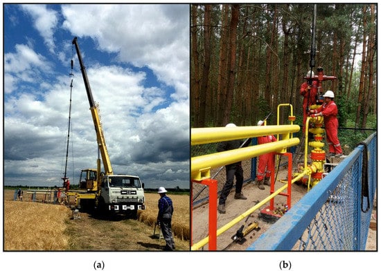
Figure 1.
Sampling of bottomhole samples; (a) assembling lubricator at B-24 well; (b) pulling out the bottomhole samplers from the B-22 well lubricator.
Within the SECURe project, 10 operations of bottomhole sampling of reservoir water underlying the Borzęcin gas reservoir were carried out within two campaigns in 2018–2019. The majority of bottomhole sampling operations were successful. Samples of reservoir water saturated with gas were obtained from wells B-4, B-6, B-22, and B-24. In wells B-4, B-6, and B-24 it was possible to obtain the research material twice—year after year—which is an additional advantage for comparative analyses. Despite attempts, no bottomhole samples from wells B-21, B-27, and B-30 were obtained. The main reason was the lack of water at the pre-set depth of samplers driving—albeit there were attempts to drive them to the maximum safe depth determined by the drift mandrel with an overflow bailer driven down to the well.
In the two producing wells (B-4 and B-22), the gas saturation with water was increased, approximately 0.6 Nm3/m3 (gas dispersed and dissolved), in the others closed, the gas saturation was at dissolved gas level, i.e., 0.3 Nm3/m3. Figure 2 presents the location of wells on the structural map of Borzęcin reservoir. The B-28 injection well is marked with a black square. The wells, where sampling of reservoir water was successful, are marked with green triangles, while those, from which despite efforts made, were not possible, with red ones.
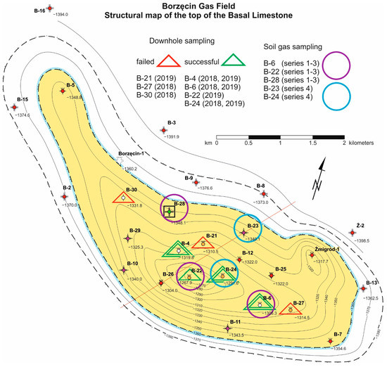
Figure 2.
Map of Borzęcin reservoir—sampling activities [16].
3. Gas Analyses
As previously described, after the separation of water and gas phases, gas and water samples for further tests were obtained. Their volume was measured, they were then sealed for transport to the laboratory. Water samples were subject to detailed physical and chemical analyses. The samples of gas released from the reservoir water were subject to chromatographic analyses and isotope composition determinations (abundance of each isotope in atom %). To perform chromatographic analyses of gas, a two-channel gas chromatograph was used—Agilent 7890A. A Nickel Catalyst Tube G2747A connected with a flame detector was used to determine trace amounts of CO and CO2. Argon and nitrogen were used as the carrier gas in gas chromatography. The uncertainty of individual components measurement is 3%. The isotopic composition of stable carbon, hydrogen, and nitrogen isotopes was performed using Trace GC Ultra chromatograph (30-m HP-PLOT/Q capillary column with a diameter of 0.32 mm) coupled with Delta V Advantage isotope ratio mass spectrometer.
3.1. Gas Released from the Reservoir Water
The recording, in the tested gas composition, of increased (in respect to the natural) concentrations of components of the gas injected to the reservoir (such as CO2 and H2S) is an important piece of information on directions and intensity of acid gases migration within the structure. The simplified results of gas analyses are presented in Figure 3.
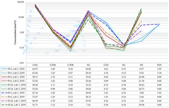
Figure 3.
Composition of the gas dissolved in the Borzęcin reservoir water.
It should be noted that from certain wells (B-4, B-6, B-24) samples were taken twice (in 2018 and 2019), and, in addition, a part of those samples were analysed in separate laboratories. Methane is the main hydrocarbon component of the gas released from the reservoir water, with an average content of approximately 60 mol% based on 10 analyses. The next are: ethane (1.4 mol%) and propane (0.16 mol%)—the other hydrocarbon components are negligible (below the significance level to the studied phenomena), and they were not included in the presented specification. The non-hydrocarbon components are dominated by nitrogen (approximately 20 mol%), followed by carbon dioxide (on average 1.5 mol%, but in samples originating from the B-4 well its amount is highest, reaching 4.6 mol%). Small amounts of helium (on average slightly more than 0.1 mol%) were also identified in each sample. Additionally, strongly varying hydrogen concentrations were determined in the studied gases. For two productive wells (B-4 and B-22), the values are relatively low, i.e., on average, approximately 1.3 mol%, while for the other wells, turned out from gas production, the hydrogen concentrations were much higher—on average 30 mol%. The highest hydrogen concentrations (reaching almost 40 mol%) were recorded in the B-24 well, which will be discussed hereafter. Hydrogen sulphide, on an average level of 3.4 mol%, was identified only in the gas samples from the B-4 well.
To estimate the direction and intensity of acid gases migration, the CO2 and H2S concentration in relation to the distance from the injection well was also analysed. Studies showed that water originating from the Borzęcin-4 well is saturated to the largest extent with carbon dioxide and hydrogen sulphide, hence the acid gases reinjected to water-bearing layers. In each of the three analyses of gas released from the B-4 reservoir water, the determined groups exceeded many times the levels observed in the other wells from which bottomhole samples were taken (B-6, B-22, B-24). The analysis of arrangement and mutual distances of the wells mentioned above to the injecting well helps understand the concentration distribution. As shown in Figure 2, the B-4 well is situated closest to the well injecting acid gases. Moreover, it is located south of B-28, that is in the direction of the expected migration of acid gases upwards the structure, directed by gravity forces, but also by a depression of pressure caused by continuous gas production from the reservoir—now by four wells, i.e., B-4, B-21, B-22 (most productive), and B-27. It also should be noted that the gas containing hydrogen sulphide at an average level of 3.4 mol% was detected only in samples originating from the B-4 well (along a straight line 630 m away from the B-28 well). This is a very high concentration, considering that in samples from the other wells hydrogen sulphide was not identified at all.
Considering the chromatographic results, attention should be paid to the unusually high concentration of hydrogen originating from the B-24 well, which has been out of operation since 2013. During the workover carried out in 2014, the set of tubing section in the well was replaced. Unfortunately, part the of tubing section was lost and left in the well. The last pulled out production tubing section was entirely damaged by corrosion. Despite reconstruction works, no satisfactory gas production was achieved, and the well remains out of operation. Some information on the well history was provided here to explain that in the gas originating from the B-24 well, record hydrogen concentrations of 26 ÷ 40 mol% were registered. Unexpectedly high hydrogen concentrations were the reason for transferring the backup gas samples to an additional laboratory (Lab-2) to verify the analysis. The confirmed very high hydrogen concentration is related to progressing corrosion of the lost part of the tubing. The bottomhole brine was sampled approximately 13 m above the tubing failure. It features a very low degree of saturation with gas, estimated on average at 0.2 Nm3/m3, therefore, already small amounts of hydrogen can substantially increase its percentage concentration. The well remained out of operation for years, resulting in minimal water exchange between the well annulus and the aquifer. This provides favourable conditions for progressive corrosion, which leads to continuous water saturation with hydrogen. The methane, nitrogen, and other gas components contents are necessarily proportionally lower at very high hydrogen concentrations. No hydrogen sulphide was found in any of the analysed samples, which could be partially related to the H2S consumption during the corrosion reaction. The carbon dioxide concentration, on average, is 0.14 mol%, so it maintains a very low level. It should be concluded that the acid gases migration did not also reach the out-of-operation B-24 well.
3.2. Produced Gas
The gas from the Borzęcin reservoir is currently produced with four wells, i.e., B-4, B-21, B-22, and B-27. Samples of the gas, produced by individual wells and of water produced with gas, were taken from the surface installation in May 2019. The samples for testing were taken from the reduction-measurement lines, separate for each productive well [17,18]. The analyses showed that methane prevails among hydrocarbon gas components, with an average content of 66.77 mol%; the next ones are ethane (1.91 mol%) and propane (0.31 mol%)—the other hydrocarbon components due to their negligible concentrations are omitted. The non-hydrocarbon components are dominated by nitrogen (on average 30.16 mol%), carbon dioxide is next (on average 0.41 mol%, but in samples originating from the B-4 well its amount is highest—0.68 mol%). The analysis of gas released from bottomhole water samples revealed increased CO2 and H2S concentrations only in the B-4. As shown in Figure 2, the B-4 well is located closest to the well injecting the acid gas. Therefore, there is a phenomenon of increasingly rising penetration of the injected gas to the produced gas. Additionally, small amounts of helium (on average 0.18 mol%, at relatively small concentration differences between the wells) were identified in each of the four producing wells. In addition, small hydrogen concentrations (approximately 0.01 mol%, but in the B-4 again, the highest, 0.03 mol%) were determined in the tested gases. Hydrogen sulphide was identified in the gas from each well. Its amount is highest in the gas from the B-4 (0.18 mol%) and from the B-27 (0.15 mol%), albeit the analysis of historical data shows that H2S concentrations exceeding 0.2 mol% were determined in the past. The results are summarized in Figure 4.
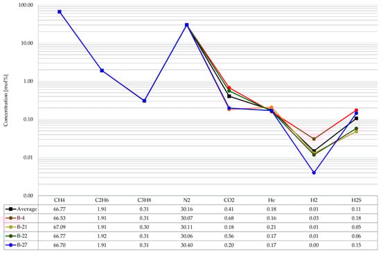
Figure 4.
Composition of the produced gas.
3.3. Injected Gas
In February 2020, a pressurized gas sample was taken from the acid gases injection installation. Currently reinjected to the Borzęcin reservoir gas composition, revealed using chromatographic analysis is shown Figure 5. Carbon dioxide prevails among the main gas components (with an average concentration of 79.9 mol%), hydrogen sulphide is next (on average 19.0 mol%). In general, the acid components (CO2 + H2S) constitute 99% of the injected gas composition. Minor amounts of hydrocarbon components are the remainder. Methane was identified with an average content of 0.93 mol%, the next ones are ethane (0.04 mol%), and propane (0.01 mol%). The other hydrocarbon components were omitted in the presented specification due to their negligible concentration. Trace amounts of helium and hydrogen appear occasionally; in most cases, both gases are below the threshold of method detectability (<0.01 mol% for He and <0.001 mol% for H2).
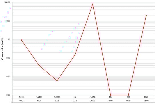
Figure 5.
Current composition of the injected gas.
3.4. Isotopic Composition
Molecular and isotopic compositions of gases can provide information on their origin, maturity, and crucially on compositional change due to migration [19]. Their applications for development, production, and operation issues are increasing [20,21]. The determination of isotope composition of stable carbon, hydrogen, and nitrogen isotopes in gas dissolved in brine and in the produced (free) gas was performed. It allowed to investigate the possible temporal and spatial variability and to make an attempt to assess the migration of the injected gas components based on analyses from individual wells. In 2018, isotope determination was carried out for gas from degassing of downhole reservoir brine samples from the B-4, B-6, and B-24. A year later, in addition to repeated isotope determination in the above wells, an analysis for the B-22 well was also successfully completed. These are the first studies of such type at that site. As part of the isotope analyses, the values of carbon (δ13C) in methane, ethane, propane, and carbon dioxide, deuterium (δD) in methane, and nitrogen (δ15N) in molecular nitrogen were determined. In total, in the framework of the SECURe project, the above isotope composition was determined for 11 samples, including 3 brine degassing gas samples drawn in 2018, 4 brine gas degassing samples, and 4 produced gas samples drawn in 2019.
The isotope composition of carbon in methane ranged from −35.9‰ to −34.4‰ (average −35.1‰), in ethane from −30.57‰ to −30.1‰ (average −30.2‰), in propane from −26.4‰ to −26.0‰ (average −26.2‰), and in carbon dioxide from −17.58‰ to −3.71‰ (average −10.4). The isotope composition of hydrogen in methane was in the range of: −133.5‰ ÷ −106.9‰ (average −118.4‰), while the isotope composition of nitrogen ranged from −0.4‰ to 5.2‰ (average 3.4‰).
A relationship of the carbon stable isotopes values in methane and carbon dioxide is used to determine the genetic type of the gas (Figure 6).
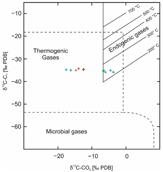
Figure 6.
Carbon isotopic composition of methane versus carbon dioxide [22].
The location of points corresponding to the analysed samples on the graph of the δ13C-C1 and δ13C-CO2 relationships indicates mainly the thermogenic origin of the gas, although a shift of some points towards the area typical for endogenous gases is also noticeable (Figure 6). The shift of those results towards the area of endogenic gases can be attributed to the enrichment of carbon dioxide in the heavy 13C isotope and it applies to some of the samples of gas dissolved in brine, drawn both, in 2018 and 2019. In the samples of gas dissolved in brine carbon isotopic composition of CO2 could be shifted towards heavier values as a result of easier dissolving of isotopically lighter CO2 in brine. Such dissolution results in enrichment of CO2 with 13C in natural gas. The enrichment of carbon dioxide in a heavier isotope may result from pressure changes in the reservoir caused by annual downtime and release of gas from the blind parts of the reservoir (ventilation/homogenisation). Such an enrichment in the heavier 13C isotope can also result from the reduction of carbon dioxide.
The isotope composition of carbon in methane, ethane, and propane appears to be unchanged and independent of the type of gas sample drawn and the time of sampling. The differences in the extreme values of carbon isotope composition in methane are about 1.5‰ (approximately 4%) and, in ethane and propane, ca. 0.4‰ (approximately 1.5%).
However, some changes in the isotope composition of hydrogen in methane are noticeable. The isotope composition of hydrogen in the extracted gas samples is distinguished by enrichment in a heavier isotope, the deuterium, relative to gas samples from brine degassing drawn in 2019 (Figure 7).
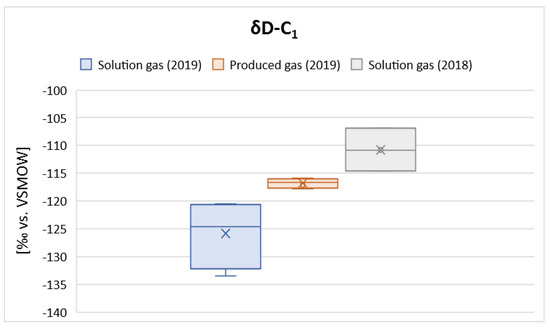
Figure 7.
Variability of the isotope composition of hydrogen in methane.
4. Reservoir Water Analysis
The analyses of physiochemical parameters of bottom water underlying the Borzęcin reservoir were carried out by testing downhole samples drawn from the productive wells B-4, B-6, B-24, and B-22 and surface samples of water drawn from the wells B-21, B-22, and B-27. The tests of the downhole samples in wells B-4, B-6 and B-24 were repeated at approximately one-year interval.
In most cases, the analysed water is in the form of reservoir brine. Only the samples drawn from the B-22 (downhole sample) and B-22 (surface sample) wells bear the marks of condensation water and will not be a part of further considerations.
The liquid was from colourless to yellowish green. In most cases, the liquid had an opalescent suspension of sulphides visible to the naked eye. The odour of hydrogen sulphide was clearly perceptible.
The amount of substances dissolved in the analysed samples falls within the range 228 to 251 g/L, with 243 g/L on average. The density takes values in the range 1.153 to 1.166 g/cm3, 1.156 g/cm3 on average. The conductivity is on average 205 mS/cm. The pH of the samples analysed ranges from 4.5 to 6.5 with an average of 5.4. The chemical composition of the brine analysed is dominated by chloride and sodium ions. The percentage of chloride ion among anions is greater than 99%. While that of sodium ions among cations is ~78%. The averaged percentage of anions and cations (%mval) is shown in Table 1.

Table 1.
Average ionic composition of the reservoir brine.
Differences in the concentration of individual components between samples drawn from individual wells are insignificant and, in the case of anions, even negligible (on average below 0.1 percentage point). For cations, the differences observed, mainly concerning Ca2+ and K+, are slightly higher and amount to a maximum of ~3 percentage points.
The chemical analyses repeated for the same wells at an annual interval did not show significant changes in the concentration of individual components over time either. A slight increase in the percentage of Na+. NH4+ and Mg2+ cations can be observed at the cost of the Ca2+ and K+ ones. However, those changes are slight, below 1 percentage point.
In the water samples analysed, the presence of dissolved hydrogen sulphide was found in the range of 0.015 to 0.065 g/L (0.039 g/L on average) and sulphides in the range of 0.0016 to 0.0056 (0.0033 g/L on average).
Salinity and alkalinity of brine calculated by the Palmer method [4], take the following averaged values:
- First order salinity: 79.45;
- Second order salinity: 20.49;
- Second order alkalinity: 0.05.
Table 2 presents a set of hydrochemical indicators calculated on the basis of the ionic content of individual components
Table 2.
Average hydrochemical indicators.
Based on the physiochemical parameters and hydrochemical indicators presented above, it can be stated that the bottom water underlying the Borzęcin reservoir, to which acid gas is injected, is composed of approximately 24% Cl-Na binary brine. According to Sulin classification [23], it is a calcium chloride type. The values of hydrochemical coefficients indicate a high degree of metamorphosis of the brine analysed. It is a quality typical of highly metamorphosed fossil brines originating from formations with very high hydrogeological tightness. Local variability in the chemical composition of brine is highly related to the performance of the wells injecting waste brine. Reservoir water with diverse chemistry account for the majority of waste brine injected, originating from the nearby oil and gas reservoirs.
5. Solubility Study
Determination of the solubility (Rs) both of the produced gas and the acid gas reinjected to the reservoir brine was a significant test for considerations of migration of the injected gases in the aquifer underlying the Borzęcin reservoir. Solubility tests were carried out at the reservoir temperature and in five pressure steps, based on which the solubility curve was drawn. Similar studies are presented in the number of papers [24,25,26], however it was crucial to determine the solubility properties of particular fluids originating from the Borzęcin site. The injected acid gas features definitely much higher solubility in the reservoir brine, even 23 times more—depending on the pressure, than the produced gas. Figure 8 present results of solubility study—solubility coefficient versus pressure.
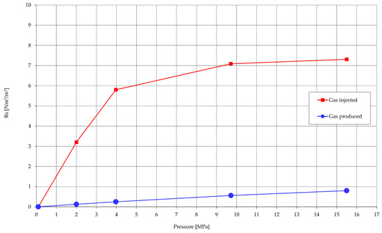
Figure 8.
Solubility of gases in Borzęcin reservoir water.
6. Soil Gas Analysis
For containment evaluation of the Borzęcin sequestration structure and the safety of acid gas storage, it was necessary to perform environmental studies, including soil gas analysis. This task aimed to investigate changes in the soil gas composition of the ground located directly above the reservoir [27,28]. Currently, these areas are mainly agricultural (cultivated fields, and partly forested). The study was conducted in four cycles between October 2019 and March 2020.
At selected sampling points, mainly around the wellheads, drive-in probes were installed, or appropriately designed monitoring wells were dug in to facilitate the inflow and collection of soil gas from a given area. Then, the chromatographic analysis of the collected gas was conducted to reveal its chemical composition. The composition of soil gas was analysed along with its variation potentially resulting from different locations of sampling points, different age, and purpose of the wells around which the probes were placed or different time of sampling (e.g., autumn vs. winter) [29].
6.1. Well Selection and Sampling—Measurement Series 1–3
In order to determine the potential influence of sour gases injection into the Borzęcin reservoir on soil air composition, the measurements of its composition were performed. The air specimens were sampled from monitoring wells, located at three boreholes, that is B-6—currently inactive, observation borehole, although most of gas from this reservoir has been produced by this borehole; B-22—currently the best producer, and B-28—the borehole injecting sour gases into an aquifer, underlying the natural gas reservoir—Figure 2.
The Borzęcin-28 borehole was drilled in 1987. Despite several intensification jobs, including two-stage acid-treatment, an industrial production of gas was not achieved from it, so it has been intended for liquidation. In 1994, workover jobs have been completed to adapt the well for sour gas reinjection. The B-28 well is the crucial element of sour gas reinjection on the Borzęcin sequestration facility, and its proper technical condition is principally decisive of whole undertaking safety.
The monitoring wells were installed on October 2019. They were located directly at the wells (at the wellhead within the near well zone) and at a distance of approximately 35 m from the wellhead. An example of the location of the measuring points at the B-6 well is shown in Figure 9.
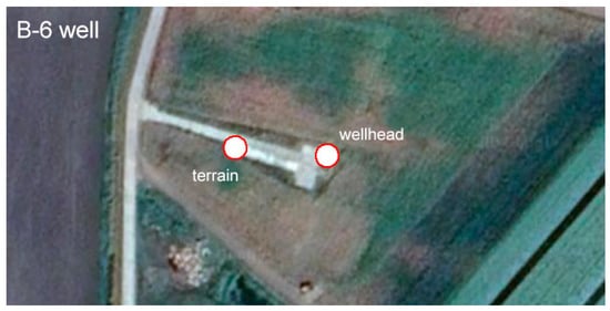
Figure 9.
Location of measuring points at the B-6 well.
The gas was sampled from six 2-metre-deep monitoring wells. A monitoring well was made of PE pipe embedded in gravel backfill. In the lower part of the pipe, along an 80 cm section, there was a perforation made enabling the free inflow of soil gas. The sampling was carried out using glass pipettes and a vacuum pump—Figure 10.
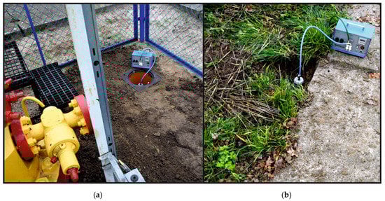
Figure 10.
Soil gas sampling from a monitoring well located within the B-28 well pad: (a) from a monitoring well located within the B-28 well pad; (b) from a monitoring well located within 35 m of the B-28 wellhead.
6.2. Determination of the Sampled Gas Composition—Measurement Series 1–3
The composition of gas sampled in the first three measurement series was examined. Chromatographic analyses of the sampled gas were performed using a two-channel valve Clarus 680 GC Perkin Elmer-Arnel chromatograph with thermal conductivity (TCD) and flame ionisation (FID) detectors. The apparatus was coupled with TotalChrom Navigator software. A total of three measurement series were completed. No hydrogen sulfide was detected (threshold of 0.0001 mol%) in any of the samples, while carbon dioxide concentrations did not exceeded acceptable natural levels associated with agricultural areas and ranged 0.1 to 0.7 mol%. Simplified chart with hydrocarbons content in samples taken at the B-6, B-22, and B-28 wells (series 1–3) is presented in Figure 11.
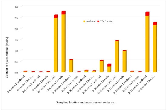
Figure 11.
Hydrocarbons content in samples taken at the B-6, B-22 and B-28 wells.
Among the results from the first three measurement series, no values were observed which could suggest uncontrolled emission (leakage) of injected acid gases into the soil air. However, due to the presence of higher hydrocarbons in some samples, it was decided to perform another series of measurements, taking into account an increased number of measuring points around the indicated productive wells.
6.3. Wells Selection and Sampling—Measurement Series 4
Two wells were selected for further examination: B-23—the well injecting waste brine into the reservoir and B-24—the well in which progressing corrosion has led to a partial loss of production tubing. The B-23 well has been producing gas from the reservoir since 1988. The well has been inactive since December 1997 due to water encroachment. In 2004, the well was reconstructed to adapt it for waste brine injection (mainly water produced from other reservoirs). In 2005 and 2007, injectivity tests were performed on the well. For two years it has been one of the four wells through which waste brine to the Borzęcin reservoir is injected. The B-24 was productive well since 1985 till 2013, when during workover a section of tubing was lost, and the well remains out of production. Within the SECURe project, the downhole reservoir water sampling was performed twice in the B-24 well (in September 2018 and July 2019). The sampling depth was 1330 m below ground level. Chemical analyses of the gas separated from the brine demonstrated an increased concentration of hydrogen—over 30 mol%, which, given the above producing tubing issue, can prove the occurrence of electrochemical corrosion and hydrogen release in the well. Therefore, the B-24 well was selected for the extended examination of the soil air composition.
Around the two wells selected for measurements, 18 driven-in monitoring probes were deployed, each with a 1 m depth, 9 units per well. The measuring points were centrally located within approximately 25 m and 50 m distances from the wells and at the wells themselves—Figure 12. A hammer drill was used to make the holes for the probes. Then, a perforated PE pipe with a socket with a built-in measuring connector was placed in the holes. Perforation made on a part of the pipe allowed free flow of soil gas into the probe. The probes were installed in such a manner that the measuring connections were located at the ground surface. After 9 days, soil air samples from the installed probes were drawn into glass bulbs and handed over for further analysis. Samples were taken from 16 holes. Sampling soil air from two probes located beside the B-24 well was unsuccessful. That was presumably caused by the groundwater level being too high, preventing free flow of air into the probes.
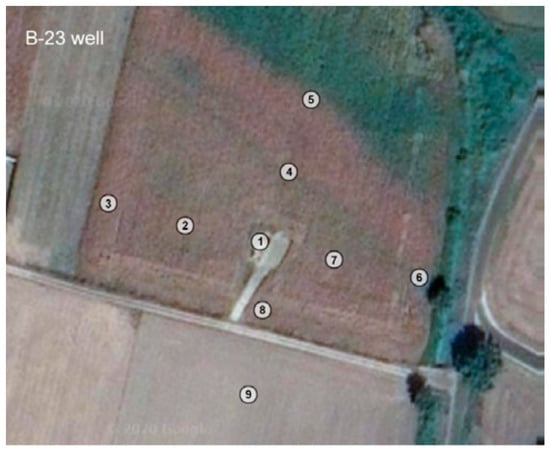
Figure 12.
Location of measuring points around the B-23 well.
6.4. Determination of the Sampled Gas Composition—Measurement Series 4
Examination of gas composition from 16 samples contained in glass bulbs within the fourth measurement series was performed. As in the measurement series 1–3, no hydrogen sulphide was detected (threshold of 0.0001 mol%) in any of the samples, while carbon dioxide concentrations did not exceeded acceptable natural levels associated with agricultural areas and ranged 0.1–2.1 mol%. Simplified chart with hydrocarbons content in samples taken at the B-23 and B-24 wells (series 4) is presented in Figure 13.
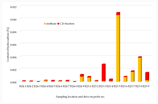
Figure 13.
Hydrocarbons content in samples taken at the B-23 and B-24 wells.
The potential negative impact of acid gases injection into the Borzęcin reservoir should be considered primarily in terms of the possibility of direct uncontrolled leakage of acid gases into the soil air along the production well structure. That process could then be manifested by an increased content of, in particular, CO2 as the dominant component, and the presence of H2S in the soil air. In order to determine the potential of such hazards, a total of 24 monitoring wells/probes were deployed, and 34 soil air samples were drawn for examination.
Among all the results of analyses carried out in series 1–4, including the B-28 well used for injecting acid gases into the reservoir, no values were observed that could suggest uncontrolled emission of injected gases into the soil air. Analysing the results, it should be kept in mind that carbon dioxide is a gas that is part of typical soil air, and the main factors affecting its level include the activity of microorganisms and the roots of higher plants, temperature, humidity, depth, soil aeration degree, and atmospheric pressure. Furthermore, the area where the research was conducted should be taken into account. In the case of the four wells, it was an agricultural area, and forest for the B-6 well. Organic substances occurring naturally in the soil or penetrating into it as a result of human activity (natural fertilizers, crops residues) are subject to digestion and fermentation processes during which biogenic gas is generated, which consists mainly of carbon dioxide (CO2) and methane (CH4). It can, therefore, be concluded that the low methane concentrations found in some samples are also a consequence of natural processes occurring in the soil. The CO2 levels observed should, therefore, be assumed to be absolutely normal for the type of area [29]. Moreover, the lack of even trace amounts of hydrogen sulphide (H2S) in the samples examined proves the absence of uncontrolled emissions into the soil.
Out of the first three measurement series, completed at the B-6, B-22, and B-28 wells, the results of the third measurement series at the B-6 well and the first and third series at the B-22 well depart from the typical soil air composition that can be found in agricultural areas. The high level of methane (approx. 2.5%) and, in particular, the presence of higher hydrocarbons is likely to result from local gas exhalations from the reservoir. Those exhalations may take place along casing and cement, which may be indicated by higher levels of contaminants in the samples drawn directly at the wells. Increased methane and ethane values in samples drawn from the B-28 well, in the first and third series, due to the trace content of C3 and higher hydrocarbons, are most likely caused by natural processes occurring in the soil. Those compounds may also have an anthropogenic origin, e.g., soil pollution by ongoing farming and the use of heavy equipment. The remaining samples from series 1–3 contained insignificant amounts of methane, which can be considered as the regional geochemical background.
The fourth measurement series was completed at the B-22 and B-24 wells. The presence of small amounts of methane in soil air samples (up to 0.01%) is a consequence of digestion and fermentation processes (e.g., natural fertilisers), during which biogenic gas is produced. In none of the samples was the content of higher hydrocarbons found in quantities which could imply significant gas exhalations from the reservoir.
7. Summary and Conclusions
The extensive sampling and testing campaign results, including reservoir fluids and soil gas analyses, are vital sources of knowledge concerning the phenomena occurring in the sequestration structure due to acid gas injection. All the activities conducted are summarised in Table 3.
Table 3.
Sampling and testing activities.
Downhole samples of water saturated with gas are very valuable material for research, and their proper utilisation gives a lot of useful information for better understanding of the processes occurring within the Borzęcin reservoir. So far, such samples have never been obtained before.
Conducted actions and measurements allowed to reach the main goal of the research, which was the identification of acid gas migration characteristics within the structure and potential leakage pathways. The results of solution gas analysis revealed that the acid gas injected into the aquifer through the B-28 injector well migrate southwards towards the B-4 well. The investigations proved that this is the main direction of the injected acid gas plume propagation. Water taken from the B-4 well is most intensely saturated with reinjected carbon dioxide and hydrogen sulphide. In each of the three analyses of gas separated from B-4 reservoir water, the concentration of CO2 and H2S exceeded many times the levels observed in the other downhole-sampled wells. The B-4 well is closest to the B-28. Moreover, it is located in the direction consistent with the expected migration of acid gas upward the structure, driven by gravity forces as well as by pressure depletion caused by continuous gas production from the reservoir (especially by the B-4 and B-22 wells, where B-22 accounts for 80% of current production).
Research actions were also related to the surface sampling of gas and associated water. As in the case of gas separated from the reservoir water, the chemical analysis of produced gas confirmed the inflow of the injected acid gas into the gas produced (especially) by the B-4 well. Furthermore, an increased concentration of CO2 was also recorded in the gas produced by the B-22 well, which may indicate that the migration zone of the injected acid gas is going to affect the major production well.
Samples of the acid gas were also taken from the reinjection facility. The results of the chemical analysis confirmed stability in the composition of the gas over time. Currently, after the modernisation of the acid gas sweetening facility, the reinjected gas is composed mainly (in 99 mol%) of carbon dioxide and hydrogen sulphide, while the hydrocarbon components represent less than 1 mol%.
The high dynamics of individual phase systems occurring in the structure of the Borzęcin reservoir implies temporal and spatial variability in the isotope composition of the analysed gas from brine degassing and of the produced gas. The system is subject to periodic disturbances related to the process of reservoir exploitation, repeated injection of acid gases and waste brine coming from outside the reservoir. Moreover, the solubility of CO2 in brine and isotope fractionation (hydrogen between methane and brine) may also affect the isotope composition of carbon in CO2 and hydrogen in methane for the brine degassing samples. Additionally, other processes, as microbial or abiotic oxidation of C1 might play role in the d2H (C1) variations.
Based on the physiochemical parameters and hydrochemical indicators, it can be stated that the water underlying the Borzęcin reservoir, to which acid gas is injected, is composed of approximately 24% Cl-Na binary brine. According to the Sulin classification [23], it is a calcium chloride type brine. Local variability in the chemical composition of brine is highly related to the performance of the wells injecting waste brine. Reservoir water with diverse chemistry account for the majority of waste brine injected, originating from the nearby oil and gas production facilities.
Among others, the ability to dissolve the produced and reinjected gases in the reservoir water was also examined. The studies showed that acid gas has excellent solubility in Borzęcin reservoir water. In the current thermobaric reservoir conditions, the solubility of acid gas is about 20 times higher than of the produced gas. This feature indicates that a significant volume of acid gas injected directly into the aquifer dissolves in water and migrate within the structure, remaining in the water zone. This is a positive phenomenon when concerning acid gas sequestration within an active gas reservoir. The dissolution of CO2 and H2S in the reservoir water certainly delays the breakthrough of these components into the natural gas zone.
The soil air analyses carried out so far did not reveal surface leaks of acid gases injected into the Borzęcin structure. Periodically elevated hydrocarbon concentrations at the B-6 and B-22 wells are likely to occur due to natural gas exhalation. To ascertain what their origin is, it is recommended to perform long-term monitoring tests on the identified wells that could be the future venues of research.
Author Contributions
Conceptualisation, M.W. (Marcin Warnecki) and M.W. (Mirosław Wojnicki); methodology, M.W. (Marcin Warnecki) and M.W. (Mirosław Wojnicki); investigation, M.W. (Marcin Warnecki); J.K., S.S. and M.W. (Mirosław Wojnicki); writing—original draft preparation, M.W. (Marcin Warnecki); writing—review and editing, M.W. (Mirosław Wojnicki). All authors have read and agreed to the published version of the manuscript.
Funding
This report is part of a project that has received funding by the European Union’s Horizon 2020 research and innovation programme under grant agreement number 764531. Project acronym and title: SECURe—Subsurface Evaluation of Carbon capture and storage and Unconventional Risks. D2.2 Report on effects of long-term sequestration process in the Borzęcin structure—observation evidence of the injected gas migration and possible leakage.
Institutional Review Board Statement
Not applicable.
Informed Consent Statement
Not applicable.
Conflicts of Interest
The authors declare no conflict of interest.
References
- Bachu, S.; Gunter, W.D. Acid-gas injection in the Alberta basin, Canada: A CO2-storage experience. Geol. Soc. Lon. Spéc. Publ. 2004, 233, 225–234. [Google Scholar] [CrossRef]
- Bachu, S.; Gunter, W. Overview of acid-gas injection operations in Western Canada. In Greenhouse Gas Control Technologies 7; Elsevier Inc.: Amsterdam, The Netherlands, 2005; pp. 443–448. [Google Scholar] [CrossRef]
- Wong, S.; Keith, D.; Wichert, E.; Gunter, B.; Mccann, T. Economics of Acid Gas Reinjection: An Innovative CO2 Storage Opportunity. In Greenhouse Gas Control Technologies—6th International Conference; Elsevier Inc.: Amsterdam, The Netherlands, 2003; pp. 1661–1664. [Google Scholar] [CrossRef]
- Lubaś, J.; Szott, W. 15-year experience of acid gas storage in the natural gas structure of Borzęcin—Poland. Nafta-Gaz 2010, 66, 333–338. [Google Scholar]
- Lubaś, J.; Szott, W.; Jakubowicz, P. Effects of Acid Gas Reinjection on CO2 Concentration in Natural Gas Produced from Borzęcin Reservoir. Nafta-Gaz 2012, 68, 405–410. [Google Scholar]
- Baroni, A.; Estublier, E.; Deflandre, J.P.; Daniel, J.M. Modelling surface displacements associated with CO2 reinjection at Krechba. In Proceedings of the 45th US Rock Mechanics/Geomechanics Symposium, San Francisco, CA, USA, 26–29 June 2011. [Google Scholar]
- Ringrose, P.; Mathieson, A.; Wright, I.; Selama, F.; Hansen, O.; Bissell, R.; Saoula, N.; Midgley, J. The In Salah CO2 Storage Project: Lessons Learned and Knowledge Transfer. Energy Procedia 2013, 37, 6226–6236. [Google Scholar] [CrossRef] [Green Version]
- Van der Meer, L.G.H. The K12-B CO2 injection project in the Netherlands. In Geological Storage of Carbon Dioxide (CO2): Geoscience, Technologies, Environmental Aspects and Legal Frameworks; Elsevier Inc.: Amsterdam, The Netherlands, 2013. [Google Scholar] [CrossRef]
- Vandeweijer, V.; Hofstee, C.; Graven, H. 13 years of safe CO2 injection at K12-B. In Proceedings of the 5th CO2 Geological Storage Workshop, Utrecht, The Netherlands, 21–23 November 2018; European Association of Geoscientists and Engineers, EAGE: Houten, The Netherlands, 2018. [Google Scholar] [CrossRef] [Green Version]
- Chadwick, R.A.; Marchant, B.; Williams, G.A. CO2 storage monitoring: Leakage detection and measurement in subsurface volumes from 3D seismic data at Sleipner. Energy Procedia 2014, 63, 4224–4239. [Google Scholar] [CrossRef] [Green Version]
- Williams, J. Getting the Best Out of Fluid Samples. J. Pet. Technol. 1994, 46, 752. [Google Scholar] [CrossRef]
- Yonebayashi, H.; Miyagawa, Y.; Ikarashi, M.; Watanabe, T.; Maeda, H.; Yazawa, N. How Many Back Up Prepared For Asphaltene Onset Pressure Measurement Using Costly Collected Single Phase Bottomhole Fluid Samples? In Proceedings of the SPE Annual Technical Conference and Exhibition, Dubai, United Arab Emirates, 26–28 September 2016. [Google Scholar] [CrossRef]
- Jamaluddin, A.; Ross, B.; Ross, D.; Hashem, M. Single-Phase Bottomhole Sampling Technology. J. Can. Pet. Technol. 2002, 41. [Google Scholar] [CrossRef]
- Piazza, R.; Vieira, A.; Sacorague, L.A.; Jones, C.; Dai, B.; Pearl, M.; Aguiar, H. Innovative Formation Tester Sampling Procedures for Carbon Dioxide and Other Reactive Components. Petrophys.—SPWLA J. Form. Eval. Reserv. Descr. 2021, 62, 65–72. [Google Scholar] [CrossRef]
- Gutman, R. Formation Fluid Sampling Technique Allowing to Control Physical Properties of Sampling Medium. In Proceedings of the SPE Annual Technical Conference and Exhibition, San Antonio, TX, USA, 9–11 October 2017. [Google Scholar] [CrossRef]
- Lubaś, J.; Szott, W.; Łętkowski, P.; Gołąbek, A.; Miłek, K.; Warnecki, M.; Wojnicki, M.; Kuśnierczyk, J.; Szuflita, S. Long-Term Sequestration Process in the Borzęcin Structure—Observation Evidence of the Injected Acid Gas Migration and Possible Leakage; Instytut Nafty i Gazu—Państwowy Instytut Badawczy: Kraków, Poland, 2020. [Google Scholar] [CrossRef]
- Haji, A.; Veerakumar, U. Overcoming Hazards in Sour Gas Sampling by Controlled Measures. In Proceedings of the Abu Dhabi International Petroleum Exhibition & Conference, Abu Dhabi, United Arab Emirates, 7–10 November 2016. [Google Scholar] [CrossRef]
- Balthar, A.R.; Oliveira, V.M.; Souza, J.R.; Bayer, M.M.; Macedo, V.C. The influence on gas chromatography analysis caused by the Joule-Thomson cooling effect during the natural gas sampling. In Proceedings of the 17th World Petroleum Congress, Rio de Janeiro, Brazil, 1–5 September 2002. [Google Scholar]
- Waseda, A.; Iwano, H.; Kato, S. Geochemical Evaluation of Reservoir Compartment, Effective Pay Zone and Origin of Gas Seepage in Production Site Using Gas Molecular and Isotopic Composition. In Proceedings of the International Petroleum Technology Conference, Kuala Lumpur, Malaysia, 3–5 December 2008. [Google Scholar] [CrossRef]
- Lu, F.; Harthi, O.; Dubaissi, J. Isotopic Characterization of Formation Waters: Applications and Challenges. In Proceedings of the SPE Middle East Oil and Gas Show and Conference, Manama, Bahrain, 18–21 March 2019. [Google Scholar] [CrossRef]
- Schloemer, S.; Krooß, B.M. Molecular transport of methane, ethane and nitrogen and the influence of diffusion on the chemical and isotopic composition of natural gas accumulations. Geofluids 2004, 4, 81–108. [Google Scholar] [CrossRef]
- Kotarba, M.J.; Nagao, K. Composition and origin of natural gases accumulated in the Polish and Ukrainian parts of the Carpathian region: Gaseous hydrocarbons, noble gases, carbon dioxide and nitrogen. Chem. Geol. 2008, 255, 426–438. [Google Scholar] [CrossRef]
- Tikhomirov, V.V. Hydrogeochemistry Fundamentals and Advances: Groundwater Composition and Chemistry; John Wiley & Sons, Inc.: Hoboken, NJ, USA, 2016; Volume 1. [Google Scholar] [CrossRef]
- Ratnakar, R.R.; Venkatraman, A.; Kalra, A.; Dindoruk, B. On the Prediction of Gas Solubility in Brine Solutions for Applications of CO2 Capture and Sequestration. In Proceedings of the SPE Annual Technical Conference and Exhibition, Dallas, TX, USA, 24–26 September 2018. [Google Scholar] [CrossRef]
- Kowta, R.; Erickson, D.; Barker, R.; Neville, A.; Hua, Y. Models for Calculating Corrosion Rates in Water-Saturated and Under-Saturated CO2 Systems & Water Solubility in CO2 Systems at Supercritical Conditions. In Proceedings of the Carbon Management Technology Conference, Houston, TX, USA, 15–18 July 2019. [Google Scholar] [CrossRef]
- Agarwal, R.; Li, Y.-K.; Nghiem, L. An Efficient Method for Modelling Gas Solubility in the Aqueous Phase for Compositional Simulators. J. Can. Pet. Technol. 1993, 32. [Google Scholar] [CrossRef]
- Erno, B.; Schmitz, R. Measurements of Soil Gas Migration Around Oil And Gas Wells In the Lloydminster Area. J. Can. Pet. Technol. 1996, 35. [Google Scholar] [CrossRef]
- Barker, G.W.; Brown, D.R.; Corgan, J.M.; Fisher, J.B.; Raterman, K.T.; Trent, G.L. Soil Gas Surveys: A Cost-Effective Site Assessment Technique. In Proceedings of the SPE/EPA Exploration and Production Environmental Conference, Houston, TX, USA, 27–29 March 1995. [Google Scholar] [CrossRef]
- Jóźwiak, K. Variability of concentrations of gases in the air of the vadose zone in the natural and agriculturally converted environments. Przegląd Geol. 2017, 65, 1075–1079. [Google Scholar]
Publisher’s Note: MDPI stays neutral with regard to jurisdictional claims in published maps and institutional affiliations. |
© 2021 by the authors. Licensee MDPI, Basel, Switzerland. This article is an open access article distributed under the terms and conditions of the Creative Commons Attribution (CC BY) license (https://creativecommons.org/licenses/by/4.0/).