Article

Electrochemical Hydrogenation and Corrosion Behaviour of LaNi5-xGex (x = 0.3 and 0.6) Alloys

Faculty of Production Engineering and Materials Technology, Czestochowa University of Technology, 42-201 Czestochowa, Poland
*
Author to whom correspondence should be addressed.
Energies 2021, 14(17), 5285; https://doi.org/10.3390/en14175285
Submission received: 22 July 2021 / Revised: 19 August 2021 / Accepted: 24 August 2021 / Published: 26 August 2021
(This article belongs to the Special Issue Metal Hydrides Hydrogen Storage, Thermal Management, and Applications)

Abstract

:
The capacitive and kinetic parameters of hydride electrodes obtained on the basis of single-phase LaNi5-xGex alloys (x = 0.3 and 0.6) were related to their corrosive properties. The content of the article is important from the point of view of the improvement of LaNi5 type materials for hydrogen energy storage used as anodes in NiMH batteries. The presence of large amounts of germanium (10% at.) in the alloy results in much less surface degradation compared to the low-germanium alloy (5% at.), which, on the one hand, leads to an improvement in the resistance of the high-germanium LaNi4.4Ge0.6 alloy to long-term cycling, but on the other hand, contributes to lower hydrogen absorption by this material. The maximum discharge capacity of 293 mAh g−1 was obtained for the low-germanium alloy using a charge/discharge current density of 185 mA g−1. The studied electrode also shows a lower tendency to self-discharge and a clearly higher exchange current density.

1. Introduction

The gradual depletion of conventional fossil fuels and their negative impact on the natural environment (CO2 emissions into the atmosphere, global warming), make it necessary to seek new sources of energy. Hydrogen is one of the ideal candidates for a clean energy medium due to its abundance and environmentally friendly nature. Efficient and safe hydrogen storage technologies play a crucial role in the widespread application of hydrogen energy [1]. Among the large number of considered hydrogen storage methods, the use of intermetallic AB5-type compounds seems to be promising because of their good specific characteristics to absorb/desorb hydrogen in a reversible manner at ambient temperatures and pressures [2,3,4,5,6,7,8]. Especially LaNi5 type alloys are extensively investigated materials for hydrogen energy storage as anodes in rechargeable nickel-metal hydride Ni-MH batteries [9,10,11,12,13,14,15]. Hydride electrode material for practical use should be characterized by the highest possible hydrogen absorption capacity at ambient pressure and high rates of charging/discharging processes. On the other hand, it is particularly important that the material provides high atomic hydrogen concentrations (high values of the stoichiometric index “n” in the MHn compound) at the lowest possible equilibrium pressures of hydrogen. Otherwise, some of the cathodically produced hydrogen may evolve on the M surface in the form of hydrogen gas bubbles (H2). One of the disadvantages of using LaNi5 as an anode in an Ni-MH cell is its efficiency limited to only 30–50% of its theoretical capacity [16,17]. Moreover, during subsequent discharge cycles, part of the anode undergoes irreversible degradation, which reduces the amount of available energy. Generally, the properties of LaNi5 systems can be improved by modifying the chemical composition and selecting the appropriate alloy components for which the alloy corrosion process (oxidation of metallic elements) occurring during the discharge of the electrode is partially reversible in the charging process or, alternatively, by finding anode materials with better kinetics of charging/discharging processes. There has been a great deal of research reported on the partial replacement of both the La metal [18,19] and Ni by various elements: Cu [20], Sn [21,22], Fe [23], Co [24,25], Al [26,27], Mn [28,29], and Zn [30]. There are no clear and universal criteria for selecting atoms for substitution, but one of the most noteworthy observations from these studies is the modification of the LaNi5 material by replacing nickel or lanthanum with larger atoms [31,32]. This can lead to a larger size of interstitial voids and thus a higher number of interstitial void occupied by hydrogen and, as may be expected, higher hydrogen storage capacity for modified version of material as compared to basic LaNi5. Another element that could be used as a substitute for Ni that seems to have a beneficial effect on hydrogen storage properties is germanium (the metallic radius of Ge is 10% larger than that of Ni [33]). Typical alloys that have been studied are represented by the general formula LaNi5-xGex, where x varies in the range 0.1 ≤ x ≤ 0.5 [34,35]. It has been shown that the plateau pressures for hydrogen absorption/desorption processes decrease with an increasing Ge content, as well as the kinetics of Ge substituted alloys are improved at a high Ge content. However, there are no data on the corrosion resistance and its influence on the electrochemical hydrogenation properties of the examined alloys. It is worth noting that understanding the corrosion mechanism is extremely important from the point of view of limiting the degradation of the investigated hydride electrode materials, as well as ensuring the appropriate capacitive and kinetic parameters of composite powder electrodes. Therefore, the aim of this study is to investigate the effect of partial replacement of Ni with Ge in hydride electrodes obtained on the basis of single-phase LaNi5-xGex alloys (x = 0.3, 0.6) on the values of the hydrogen capacity and the absorption/desorption kinetics in relation to the corrosion properties of the studied alloys.

2. Materials and Methods

LaNi5-xGex alloys were obtained by melting stoichiometric amounts of pure elements (99.99% purity) in an arc furnace under an argon atmosphere. Then, vacuum homogenization was applied in quartz ampoules at 600 °C for 240 h.
In order to determine the elemental composition of the examined alloys (Figure 1), energy-dispersive X-ray spectroscopy (EDS) and scanning electron microscopy (SEM) measurements were performed using a JEOL JSM-6610 LV microscope.
Data analysis confirmed that the elemental composition of the alloys within the error limits up to 1% at. does not differ from the assumed composition.
In order to determine the phase composition of the obtained alloys, diffractometric studies were carried out using a Bruker D8 Advance diffractometer equipped with a Johansson monochromator (λCu Kα1 = 1.5406 Å) and a LYNXEYE strip detector. The obtained diffractograms were analysed using the PDF4 + database.
Both solid materials (with the working surface of the electrodes in the order of 0.1 cm2) and composite powder electrodes containing 0.030 ÷ 0.035 g of a hydrogen storage alloy were subjected to electrochemical tests.
The powder electrodes were prepared by mixing a 90 wt.% active material (LaNi5-xGex alloy with 10 wt.% PVDF (polyvinylidene fluoride). The well-mixed components were moulded on a laboratory press at the pressure of 50 bar and dried at 110 °C for 1 h. For comparative purposes, a commercial lanthanum nickel intermetallic compound LaNi5 with a purity of 99.9% (Alfa Aesar GmbH & Co KG, Karlsruhe, Germany) was used.
Electrochemical measurements were performed in a classic three-electrode system using a CHI 1140A electrochemical measuring station (CH Instruments USA). A platinum spiral electrode was used as the counter electrode, and the calomel saturated electrode (SCE) was used as the reference electrode. The tests were carried out in a 6 M KOH solution at the temperature of 25 °C.
Potentiokinetic polarization curves of the LaNi5-xGex solid alloys were recorded from −1.2 to 0.5 V vs. SCE, with a scanning rate equal to 10 mV s−1. For the composite powder electrodes, the polarization curves were made at the rate of 1 mV s−1, the potential range of −1.2 to −0.7 V vs. SCE before and after 100 charge/discharge cycles.
The composite powder electrodes were hydrogen saturated using a constant charge/discharge current density of 185 or 500 mA g−1. In order to determine the rate of hydrogen transport through the examined materials, the chronoamperometric technique was employed. The fully charged and activated electrodes were discharged at constant potential E = −0.7 V vs. SCE for 10,000 s.

3. Results and Discussion

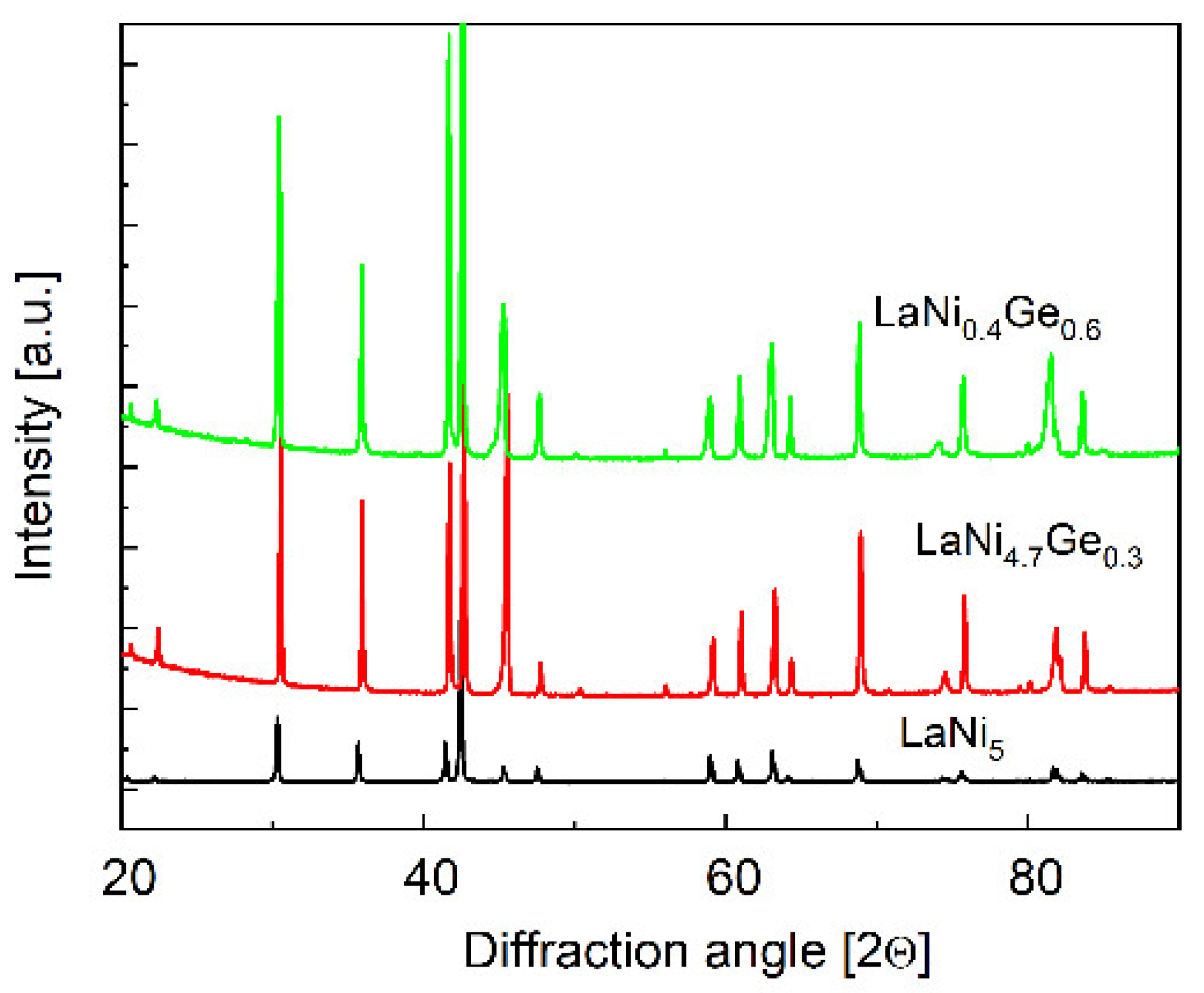
3.1. Phase Composition of the Obtained Alloys by X-ray Diffraction

Figure 2 shows the X-ray diffractograms of the investigated LaNi5-xGex alloys, where x = 0.3 and 0.6, and compared them with the diffractogram of the reference, i.e., the LaNi5 alloy. Analysis of the diffraction patterns shows that the synthesized alloys are single-phase solid solutions and have a hexagonal structure of the CaCu5 type. As seen on Figure 2, the diffraction peaks’ maximums slightly shift to lower diffraction angles when Ni was partially substituted for by Ge due to the larger size (10%) of the germanium atom compared to the nickel atom. There is an increase in the unit cell volume on substitution of Ge from value 86.6 Å for LaNi5 to 87.8 Å LaNi4.7Ge0.3 and 89.1 Å for LanNi4.4Ge0.6.

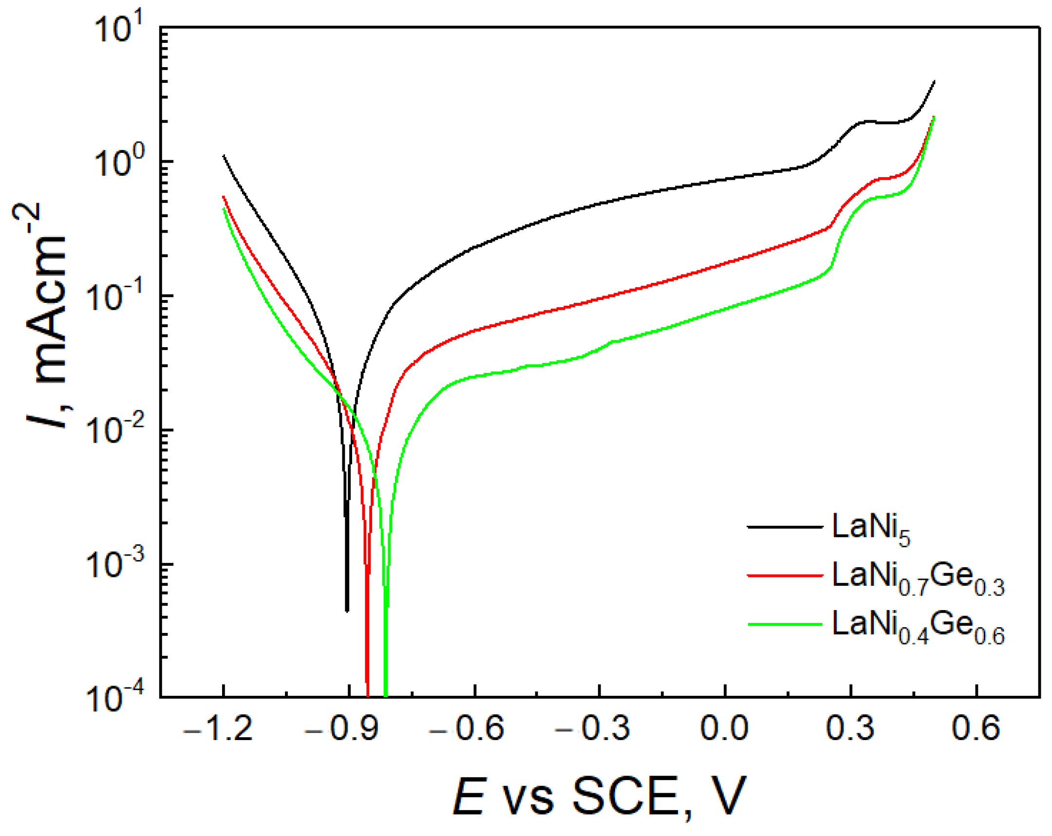
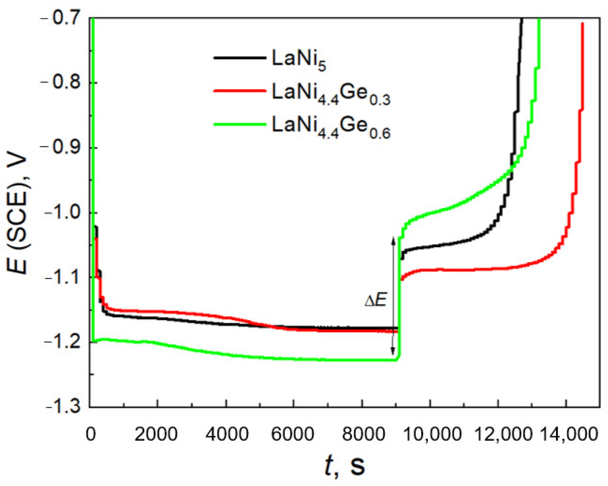
3.2. Electrochemical Measurements

The changes in the open circuit potential (OCP) for LaNi5-xGex solids as a function of time are shown in Figure 3. The potential was measured vs. SCE in a 6 M KOH electrolyte, immediately after the electrodes were immersed in the solution.
The open circuit potentials, i.e., the corrosive potentials of LaNi4.7Ge0.3 and LaNi4.4Ge0.6 are −0.7 V and −0.5 V, respectively, and are therefore significantly shifted in the anodic direction compared to the corrosion potential of the starting LaNi5 alloy. It is generally accepted that the more positive corrosion potential results in an improvement in the anti-corrosive properties of the electrode [36,37,38,39]. Therefore, alloys containing germanium should be less susceptible to corrosion in a strongly alkaline environment compared to the undoped LaNi5 alloy, which is important from the point of view of applying the above-mentioned materials in Ni-MH cells.
As can be seen from Figure 4, the partial substitution of nickel with germanium leads to about a 5–10 times reduction in anode currents in the passive range, which should provide them with greater corrosion resistance in an alkaline environment compared to the LaNi5 compound.
The current increase in the passive range, shown in Figure 4, may indicate a low tightness of the passive layers. The increase in the anode current above the potential of approx. 0.4 V is caused by the release of oxygen due to the oxidation of OH ions.
The course of the charge/discharge curves shown in Figure 5 allows to determine the values of the density of the exchange currents of the H2O/H2 system for the studied materials, based on the jump in potential ΔE during current switching according to the relationship (1) [40]:
l o g i H 2 O / H 2 o = 1 2 l o g ( i a | i c | ) Δ E 2 b     ,
where:   i H 2 O / H 2 o —Exchange current density, ic—Charging current density, ia—Discharge current density and b—Slope coefficient of Tafel lines (in alkaline solution b = 0.12 V).
As is known from text [41], cycling causes a gradual decrease in the potential jump corresponding to the switching of the cathode to the anode current, which means that with the increase in the number of cycles, the exchange current density of the H2O/H2 system increases. For the 20th charge/discharge cycle (Figure 5), the jump in potential when switching the current is: 0.19 V for LaNi4.4Ge0.6, 0.11 V for LaNi5, and 0.07 V for LaNi4.7Ge0.3. Therefore, the corresponding densities of the exchange currents H2O/H2 system amount to (mA g−1): 29.5, 63.1 and 93.3. The exchange current density obtained for the LaNi4.7Ge0.3 low-germanium alloy is therefore clearly higher than that of the high-germanium alloy LaNi4.4Ge0.6 as well as that of the reference—LaNi5. Thus, from the point of view of improving the kinetics of the charge transfer process at the electrode/electrolyte interface, it is more preferable to substitute nickel with less germanium. The use of large substitutions within the AB5 phase solid solution is definitely disadvantageous, which can also be seen when analysing the research results presented in [34,35].
As can be seen from Figure 6, the maximum discharge capacity for the LaNi4.7Ge0.3 -based powder electrode is 293 mAh g−1. Doping the LaNi5 alloy with germanium to the LaNi4.4Ge0.6 composition leads to a decrease in the measured discharge capacity, which is set at 220 mAh g−1. Moreover, the course of changes in the discharge capacity as a function of cycling indicates that the substitution of nickel with a smaller amount of germanium (x = 0.3) leads to faster activation of the alloy. As can be seen from Figure 6, the maximum discharge capacity for the electrode based on the LaNi4.7Ge0.3 alloy is obtained in the 3rd cycle, and for the material substituted with more germanium (x = 0.6) in the 14th cycle, similar to the basic LaNi5 alloy.
For longer discharge times, it is possible to determine the effective hydrogen diffusion coefficient ( D ¯ H /a2) from the slope of the rectilinear sections of the logarithm of the discharge current vs. time [42] shown in Figure 7.
The slope of logi = f (t) is in fact:
t g α = π 2 2303 D H a 2 ,
where a is the mean particle radius of a hydride material and DH is the effective diffusion coefficient.
As can be seen from Figure 7, the amount of germanium within the solid solution of the LaNi5 phase does not have a significant effect on the value of parameter D/a2 calculated on the basis of dependence (2). The D/a2 value is 2.0 × 10⁻⁵ s−1 for LaNi4.7Ge0.3 and LaNi4.4Ge0.6 electrodes, but the SEM images show different particle sizes for the tested materials, with the LaNi4.7Ge0.3 having smaller grains. Therefore, the diffusivity of hydrogen in the LaNi4.4Ge0.6 alloy electrode is evidently greater.
The self-discharge of the Ni-MH cell is a consequence of the self-discharge process of the hydride electrode, i.e., it results from the spontaneous desorption of hydrogen from the hydrogen-saturated hydrogen-absorbing material. The process of hydrogen separation from the electrode takes place due to the difference in pressure between the partial pressure of hydrogen (H2) in contact with the electrode and the equilibrium pressure of the hydride, and it is faster than the hydrogen transport rate within the solid phase. Self-discharge of the cell can be inhibited by applying a tight diffusion barrier on the electrode surface, e.g., by oxide phases resulting from corrosion of the material. Figure 8 shows the changes in the OCP potential for the studied electrodes after their complete saturation with hydrogen.
The OCP value at the level of −1.1 V indicates the H2O/H2 equilibrium, that is, it indicates the presence of the reduced form (H2) in the system. The rapid increase in potential (above −1.1 V) is linked to the spontaneous desorption of hydrogen stored in the researched material. The longer the electrode shows a potential close to −1.1 V vs. (SCE), the lower its susceptibility to self-discharge. For an electrode made on the basis of the LaNi4.7Ge0.3 alloy, the open circuit potential increases sharply after 80 h from −1.1 V to −0.97 V vs. SCE, which indicates complete hydrogen desorption and marks the beginning of oxidation of the electrode material. Figure 8 shows that the unfavourable self-discharge process associated with hydrogen desorption is much faster (about 1.5 times) for an electrode based on the LaNi4.4Ge0.6 alloy. From the analysis of work [37] it is known that the equilibrium pressure of hydrogen desorption decreases with the increase in the degree of nickel substitution with germanium in the LaNi5 alloy; therefore, the stability of the hydride is not a factor determining the faster self-discharge process of the LaNi4.4Ge0.6 electrode either. The faster self-discharge of the LaNi4.4Ge0.6 electrode material may be the result of the faster hydrogen diffusivity within the electrode and a lower concentration of hydrogen in the cathodically saturated material.
For the practical application of the electrode in hydride cells, it is important that the material shows the smallest possible decrease in discharge capacity as the cycle number increases. As shown in Figure 9, changes in the discharge capacity due to cycling indicate an increase in the stability of the hydride electrode with the increase in the germanium content in the studied LaNixGex. The value of the ratio of the discharge capacity after 100 cycles to the maximum discharge capacity (C100/Cmax × 100%) is 78 and 100% for the LaNi4.7Ge0.3 and LaNi4.4Ge0.6 alloys, respectively.
In terms of the work potentials of the investigated hydride electrodes (from −1.3 to −0.7 V vs. SCE), the oxidation of lanthanum, nickel or germanium cannot be prevented. The respective La2O3, NiO and GeO2 oxides are formed on the surface of the LaNi5-xGex alloys during the discharge processes. The highly active lanthanum (ELa/La2O3 = −2.99 V vs. SCE) will oxidize in an alkaline environment, causing the electrode capacity to drop. If the discharge stage is terminated at −0.7 V vs. SCE, also nickel (ENi/NiO = −1.03 V vs. SCE) will oxidize but the resulting NiO is reduced to Ni during the charging process. Thus, the corrosion process of nickel is reversible as opposed to the oxidation of lanthanum [43,44].
The situation is still different for GeO2, which is amphoteric and can be partially removed by etching in a strong electrolyte (KOH) [45], reducing the tightness of the passive layer and enabling the cyclic operation of the electrode.
For the practical use of Ni-MH batteries it is essential that the material exhibits as small as possible of a loss of the discharge capacity with increasing discharge rate. As can be seen in Figure 6 and Figure 9, the electrochemical capacity decreases with the increase in the discharging current density. The electrode’s ability to resist a high-rate discharge (HRD) is defined as:
H R D = Q d Q m a x · 100 %
where Qmax represents the maximum capacity (in this case at a current density of 185 mA g–1), and Qd is the capacity at the discharge current density of 500 mA g−1. The HRD is about 72% and 37% for the LaNi4.7Ge0.3 and LaNi4.4Ge0.6 composite electrode, respectively. The electrode’s ability to resist a high-rate discharge is controlled by the charge transfer processes at the surface and by the hydrogen diffusion processes in the bulk and decreases rapidly with the increasing content of germanium in alloy.
Figure 10 shows the potentiokinetic curves of the composite powder electrodes before and after 100 charge/discharge cycles in the 6 M KOH solution.
After long-term cycling, a clear increase in the density of the cathode and anode currents is visible, which can be attributed to the reduction and oxidation reactions taking place, respectively, during the charging and discharging processes of the hydride electrodes. As can be seen from Figure 10, after 100 charging/discharging cycles, the anode current density for the low germanium alloy (x = 0.3) is an order of magnitude higher than that for the high germanium alloy (x = 0.6), which proves the lower stability of the passive layer formed on the surface of the electrode obtained on the basis of the LaNi4.7Ge0.3 alloy. As a result of the cycling of LaNi5-xGex type materials, the amounts of La2O3 in the surface layers systematically and continuously rise. The presence of La2O3 in the passive layer somewhat inhibits the corrosion of the substrate; however, owing to the irreversible oxidation of lanthanum, it must lead to wear of the hydride material and reduction of the capacity in longer time intervals. Moreover, the resulting Ni (II) oxide is effectively reduced in the first stages of each charging cycle, and the Ge (IV) oxide is periodically removed, increasing the development of the specific surface of the electrode and limiting its tightness so that surface passivation does not reach a critical level, inhibiting the penetration of hydrogen. With a high germanium content in the LaNi5-xGex alloy (x = 0.6), the rate of GeO2 formation most likely exceeds its dissolution rate and surface corrosion is slower; nonetheless, the corrosion products (La2O3, GeO2) accumulate irreversibly over time and a tight passive layer forms, which on the one hand, leads to high cyclical resistance of the material, but on the other hand, to a decrease in hydrogen capacity (Figure 9). In contrast, in the case of the LaNi4.7Ge0.3 alloy, the rate of corrosive oxidation is higher, but GeO2 is periodically removed, limiting the tightness of the passive layer and causing a rise in the development of the specific electrode surface. It should be noted from Figure 11 that the surface morphology changes with the amount of germanium in the alloy.
The superior performance of the LaNi4,7Ge0.3 electrode can be explained by the increased surface of the electrode, which is associated with the presence of smaller grains after the cycling stability measurements due to pulverization of the material. As can be seen from Figure 5, this contributes to an increase in the exchange current density of the H2O/H2 system and a rise in the electrode discharge capacity. As can be seen from Figure 9 and Figure 10, the worse corrosion resistance of the LaNi4.7Ge0.3 alloy causes about 20% decline in the electrode capacity after 100 charge/discharge cycles, which was not observed for the electrode based on the LaNi4.4Ge0.6 alloy. Nevertheless, it should be borne in mind that the improvement of the corrosive behaviour of a hydrogen storage material must always be paid for by a deterioration of the kinetics of hydrogen absorption/desorption on this material.

4. Conclusions

The synthesis of LaNi5-xGex alloys (x = 0.3, 0.6) by the arc fusion of stoichiometric amounts of pure metals ensures their complete conversion, leading to obtaining materials with a single-phase structure.
The valuable property of the partial substitution of nickel with germanium in the LaNi5 alloy is clearly the better behaviour of the material in the passive state, which indicates the possibility of improving the service life of the hydride electrode material in a strongly alkaline environment.
Modification of the LaNi5 alloy to the composition of LaNi4.7Ge0.3 leads to an improvement in the electrochemical activation of the electrode and a rise in its discharge capacity by approx. 110 mAh g−1.
The effective hydrogen diffusion coefficient value is higher for the LaNi4.4Ge0.6 alloy, while smaller amounts of Ge (x = 0.3) are favourable from the point of view of the kinetics of the charge transfer process.
Too much germanium (10% at.) and at the same time a smaller amount of nickel (73.3% at.) in the LaNi4.4Ge0.6 alloy limits the penetration of hydrogen through tight passive layers, leading to a noticeable decrease in the discharge capacity—especially high-current (500 mA g−1) electrode charging and discharging conditions result in a drop in the measured current capacities.
The deterioration of the compactness of the passive layers may have negative consequences from the point of view of storage and the technology of producing electrodes from a hydrogen storage material as it will lead to accelerated corrosion of this type of material. On the other hand, from the point of view of improving the kinetics of the hydrogen absorption/desorption process, the steps towards effective passivation of the electrode material seem to be unjustified, as they will lead to a decrease in the exchange current density of the H2O/H2 system.

Author Contributions

Conceptualization, K.G. and E.O.; methodology, K.G. and E.O; validation, K.G. and E.O.; formal analysis, K.G. and E.O.; investigation, K.G. and E.O.; data curation, K.G. and E.O.; writing—original draft preparation, K.G. and E.O.; writing—review and editing, K.G. and E.O.; visualization, K.G. and E.O.; supervision, K.G. and E.O.; project administration, K.G. and E.O.; funding acquisition, K.G. and E.O. All authors have read and agreed to the published version of the manuscript.

Funding

The work was supported by the statutory research (BS/BP-200-301/2021) funds of Department of Materials Engineering, Czestochowa University of Technology, Poland.

Institutional Review Board Statement

Not applicable.

Informed Consent Statement

Not applicable.

Data Availability Statement

The data presented in this study are available on request from the corresponding author.

Conflicts of Interest

The authors declare no conflict of interest. The funders had no role in the design of the study; in the collection, analyses, or interpretation of data; in the writing of the manuscript, or in the decision to publish the results.

References

  1. He, T.; Pachfule, P.; Wu, H.; Xu, Q.; Chen, P. Hydrogen carriers. Nat. Rev. Mater. 2016, 1, 16059. [Google Scholar] [CrossRef]
  2. Schlapbach, L.; Züttel, A. Hydrogen-storage materials for mobile applications. Nature 2001, 414, 353–358. [Google Scholar] [CrossRef]
  3. Güther, V.; Otto, A. Recent developments in hydrogen storage applications based on metal hydrides. J. Alloy. Compd. 1999, 293, 889–892. [Google Scholar] [CrossRef]
  4. Dantzer, P. Properties of intermetallic compounds suitable for hydrogen storage applications. J. Mater. Sci. Eng. A 2002, 329, 313–320. [Google Scholar] [CrossRef]
  5. Eberle, U.; Arnold, G.; von Helmolt, R. Hydrogen storage in metale hydrogen systems and their derivatives. J. Power Sources 2006, 154, 456–460. [Google Scholar] [CrossRef]
  6. Klebanoff, L.E.; Keller, J.O. 5-Years of hydrogen storage research in the U.S. DOE metal hydride center of excellence (MHCoE). Int. J. Hydrog. Energy 2013, 38, 4533–4576. [Google Scholar] [CrossRef]
  7. Durbin, D.J.; Malardier-Jugroot, C. Review of hydrogen storage techniques for on board vehicle applications. Int. J. Hydrog. Energy 2013, 38, 14595–14617. [Google Scholar] [CrossRef]
  8. Kukkapali, V.K.; Sunwoo, K. Optimization of internal cooling fins for metal hydride reactors. Energies 2016, 9, 447. [Google Scholar] [CrossRef] [Green Version]
  9. Züttel, A. Materials for hydrogen storage. Mater. Today 2003, 6, 24–33. [Google Scholar] [CrossRef]
  10. Zhao, X.G.; Ma, L.Q. Recent progress in hydrogen storage alloys for nickel/metal hydride secondary batteries. Int. J. Hydrog. Energy 2009, 34, 4788–4796. [Google Scholar] [CrossRef]
  11. Jain, I.P. Hydrogen the fuel for 21st century. Int. J. Hydrog. Energy 2009, 34, 7368–7378. [Google Scholar] [CrossRef]
  12. Hong, K. The development of hydrogen storage alloys and the progress of nickel hydride batteries. J. Alloy. Compd. 2001, 321, 307–313. [Google Scholar] [CrossRef]
  13. Ouyang, L.; Huang, J.; Wang, H.; Liu, J.; Zhu, M. Progress of hydrogen storage alloys for Ni-MH rechargeable power batteries in electric vehicles: A review. Mater. Chem. Phys. 2017, 200, 164–178. [Google Scholar] [CrossRef]
  14. Jurczyk, M.; Smardz, L.; Smardz, K.; Nowak, M.; Jankowska, E. Nanocrystalline LaNi5-type electrode materials for Ni-MHx batteries. J. Solid State Chem. 2003, 171, 30–37. [Google Scholar] [CrossRef]
  15. Cuevas, F.; Joubert, J.-M.; Latroche, M.; Percheron-Guegan, A. Intermetallic compounds as negative electrodes of Ni/MH batteries. Appl. Phys. A 2001, 72, 225–238. [Google Scholar] [CrossRef]
  16. Stetskiv, A.; Rożdżyńska-Kiełbik, B.; Kowalczyk, G.; Prochwicz, W.; Siemion, P.; Pavlyuk, V. The structural and thermal stability, electrochemical hydrogenation and corrosion behavior of LaT5−xMx(T = Co, Ni and M = Al, Ge, Li) phases. Solid State Sci. 2014, 38, 35–41. [Google Scholar] [CrossRef]
  17. Dymek, M.; Bala, H. Inhibition of LaNi5 electrode decay in alkaline medium by electroless encapsulation of active powder particles. J. Solid State Electrochem. 2016, 20, 2001–2007. [Google Scholar] [CrossRef] [Green Version]
  18. Pęska, M.; Dworecka-Wójcik, J.; Płociński, T.; Polański, M. The Influence of Cerium on the Hydrogen Storage Properties of La1−xCexNi5 Alloys. Energies 2020, 13, 1437. [Google Scholar] [CrossRef] [Green Version]
  19. Clay, K.R.; Goudy, A.J.; Schweibenz, R.G.; Zarynow, A. The effect of the partial replacement of lanthanum in LaNi5-xH with cerium, praseodymium, and neodymium on absorption and desorption kinetics. J. Less Common Met. 1990, 166, 153–162. [Google Scholar] [CrossRef]
  20. Spondaryk, M.; Gasilova, N.; Züttel, A. Hydrogen storage and electrochemical properties of LaNi5−xCux hydride-forming alloys. J. Alloy. Compd. 2019, 775, 175–180. [Google Scholar] [CrossRef]
  21. Ratnakumar, B.V.; Witham, C.; Bowman, R.C., Jr.; Hightower, A.; Fultz, B. Electrochemical studies on LaNi5−xSnx metal hydride alloys. J. Electrochem. Soc. 1996, 143, 2578–2584. [Google Scholar] [CrossRef]
  22. Borzone, E.M.; Blanco, M.V.; Baruj, A.; Meyer, G.O. Stability of LaNi5−xSnx cycled in hydrogen. Int. J. Hydrog. Energy 2014, 39, 8791–8796. [Google Scholar] [CrossRef]
  23. Pandey, S.K.; Srivastava, A.; Srivastava, O.N. Improvement in hydrogen storage capacity in through substitution of Ni by Fe. Int. J. Hydrog. Energy 2007, 32, 2461–2465. [Google Scholar] [CrossRef]
  24. Liu, J.; Zhu, S.; Zheng, Z.; Cheng, H.; Yan, K.; Zhu, Z. Long-term hydrogen absorption/desorption properties and structural changes of LaNi4Co alloy with double desorption plateaus. J. Alloy. Compd. 2019, 778, 681–690. [Google Scholar] [CrossRef]
  25. Zhu, Z.; Zhu, S.; Lu, H.; Wu, J.; Yan, K.; Cheng, H.; Liu, J. Stability of LaNi5−xCox alloys cycled in hydrogen—Part 1 evolution in gaseous hydrogen storage performance. Int. J. Hydrog. Energy 2019, 44, 15159–15172. [Google Scholar] [CrossRef]
  26. Liu, J.; Li, K.; Cheng, H.; Yan, K.; Wang, Y.; Liu, Y.; Jin, H.; Zheng, Z. New insights into the hydrogen storage performance degradation and Al functioning mechanism of LaNi5−xAlx alloys. Int. J. Hydrog. Energy 2017, 42, 24904–24914. [Google Scholar] [CrossRef]
  27. An, X.H.; Pan, Y.B.; Luo, Q.; Zhang, X.; Zhang, J.Y.; Li, Q. Application of a new kinetic model for the hydriding kinetics of LaNi5−xAlx (0 ≤ x ≤ 1.0) alloys. J. Alloy. Compd. 2010, 506, 63–69. [Google Scholar] [CrossRef]
  28. Zhu, S.; Chen, X.; Liu, J.; Yang, N.; Chen, J.; Gu, C.; Cheng, H.; Yan, K.; Zhu, Z.; Wang, K. Long-term hydrogen absorption/desorption properties of an AB5-type LaNi4.75Mn0.25 alloy. Mater. Sci. Eng. B 2020, 262, 114777. [Google Scholar] [CrossRef]
  29. Chen, X.; Xu, J.; Zhang, W.; Zhu, S.; Zhang, N.; Ke, D.; Liu, J.; Yan, K.; Cheng, H. Effect of Mn on the long-term cycling performance of AB5-type hydrogen storage alloy. Int. J. Hydrog. Energy 2021, 46, 21973–21983. [Google Scholar] [CrossRef]
  30. Rożdżyńska-Kiełbik, B.; Iwasieczko, W.; Drulis, H.; Pavlyuk, V.V.; Bala, H. Hydrogenation equilibria characteristics of LaNi5−xZnx intermetallics. J. Alloy. Compd. 2000, 298, 237–243. [Google Scholar] [CrossRef]
  31. Achard, J.-C.; Percheron-Gue’gan, A.; Diaz, H.; Briaucourt, F.; Demany, F. Proceedings of the Second International Congress on Hydrogen in Metals, Paris, France, 6–11 June 1977; 1977; pp. 1–12. [Google Scholar]
  32. Singh, A.; Singh, B.K.; Davidson, D.J.; Srivastava, O.N. Studies on improvement of hydrogen storage capacity of AB5 type: MmNi4.6Fe0.4 alloy. Int. J. Hydrog. Energy 2004, 29, 1151–1156. [Google Scholar] [CrossRef]
  33. Witham, C.; Bowman, R.C., Jr.; Fultz, B. Gas-phase H2 absorption and microstructural properties of LaNi5−x Gex alloys. J. Alloy. Compd. 1997, 253, 574–578. [Google Scholar] [CrossRef]
  34. Witham, C.; Ratnakumar, B.V.; Bowman, R.C.; Hightower, A., Jr.; Fultz, B. Electrochemical evaluation of LaNi5−xGex metal hydride alloys. J. Electrochem. Soc. 1996, 143, 205–208. [Google Scholar] [CrossRef]
  35. Witham, C.; Hightower, A.; Fultz, B.; Ratnakumar, B.V.; Bowman, R.C. Electrochemical properties of LaNi5−xGex alloys in NiMH batteries. J. Electrochem. Soc. 1997, 144, 3758–3764. [Google Scholar] [CrossRef]
  36. Chu, H.-L.; Qiu, S.-J.; Sun, L.-X.; Zhang, Y.; Xu, F.; Tao, J.; Li, W.-X.; Zhu, M.; Hu, W.-Y. The improved electrochemical properties of novel La-Mg-Ni based hydrogen storage composites. Electrochim. Acta 2007, 52, 6700–6706. [Google Scholar] [CrossRef]
  37. Drulis, H.; Hackemer, A.; Głuchowski, P.; Giza, K.; Adamczyk, L.; Bala, H. Gas phase hydrogen absorption and electrochemical performance of La2(Ni,Co,Mg,M)10 based alloys. Int. J. Hydrog. Energy 2014, 39, 2423–2429. [Google Scholar] [CrossRef]
  38. Hussein, M.A.; Kumar, M.; Drew, R.; Al-Aqeeli, N. Electrochemical Corrosion and In Vitro Bioactivity of Nano-Grained Biomedical Ti-20Nb-13Zr Alloy in a Simulated Body Fluid. Materials 2018, 11, 26. [Google Scholar] [CrossRef] [PubMed] [Green Version]
  39. Kumar, A.M.; Sudhagar, P.; Ramakrishna, S.; Kang, Y.S.; Kim, H.; Gasem, Z.M.; Rajendran, N. Evaluation of chemically modified Ti–5Mo–3Fe alloy surface: Electrochemical aspects and in vitro bioactivity on MG63 cells. Appl. Surf. Sci. 2014, 307, 52–61. [Google Scholar] [CrossRef]
  40. Bala, H.; Giza, K.; Kukuła, I. Determination of hydrogenation ability and exchange current of H2O/H2 system on hydrogen absorbing metal alloys. J. Appl. Electrochem. 2010, 40, 791–797. [Google Scholar] [CrossRef]
  41. Giza, K.; Drulis, H. Effect of preparation method of metal hydride electrode on efficiency of hydrogen electrosorption process. Int. J. Mater. Res. 2016, 107, 103–108. [Google Scholar] [CrossRef]
  42. Zheng, G.; Popov, B.; White, R.E. Electrochemical determination of the diffusion coefficient of hydrogen through an LaNi4.25Al0.75 electrode in alkaline aqueous solution. J. Electrochem. Soc. 1995, 142, 2695–2698. [Google Scholar] [CrossRef] [Green Version]
  43. Giza, K.; Musiał-Gładysz, A. Evaluation of the influence of Cu2O addition on electrochemical properties of LaNi5 hydrogen storage alloy. Ochr. Przed Korozją 2018, 61, 114–118. [Google Scholar] [CrossRef]
  44. Karwowska, M.; Fijalkowski, K.J.; Czerwiński, A.A. Corrosion of hydrogen storage metal alloy LaMm-Ni4.1Al0.3Mn0.4Co0.45 in the aqueous solutions of alkali metal hydroxides. Materials 2018, 11, 2423. [Google Scholar] [CrossRef] [PubMed] [Green Version]
  45. Ocon, J.D.; Kim, J.W.; Abrenica, G.H.; Lee, J. Quasi-perpetual discharge behaviour in p-type Ge–air batteries. Phys. Chem. Chem. Phys. 2014, 16, 22487–22494. [Google Scholar] [CrossRef] [Green Version]
Figure 1. Results of EDS analysis: (a) LaNi4.7Ge0.3 (b) LaNi4.4Ge0.6.
Energies 14 05285 g001
Figure 2. X-ray diffraction patterns taken at room temperature for LaNi5-xGex alloys.
Energies 14 05285 g002
Figure 3. The open circuit potentials changes of LaNi5-xGex alloys in 6 M KOH electrolyte.
Energies 14 05285 g003
Figure 4. Polarization curves of LaNi5-xGex alloys recorded in 6 M KOH solution at a scan rate of 10 mV s−1.
Energies 14 05285 g004
Figure 5. Galvanostatic charge/discharge curves for the 20th cycle. For the LaNi4,6Ge0.6 composite electrode the way ΔE determining is demonstrated.
Energies 14 05285 g005
Figure 6. Variation of discharge capacity of the tested composite electrodes for the first 20 cycles. Charge/discharge rate: –185/+185 mA g−1 (6 M KOH, 25 °C).
Energies 14 05285 g006
Figure 7. Chronoamperometric curves of LaNi5-xGex composite electrodes at −0.7 V (SCE).
Energies 14 05285 g007
Figure 8. OCP vs. time for the hydrogen charged electrodes (6 M KOH, charge conditions: 185 mA g−1, 2 h).
Energies 14 05285 g008
Figure 9. Cyclic stability curves of LaNi5-xGex composite electrodes (charge/discharge current density: 500 mA g−1).
Energies 14 05285 g009
Figure 10. Polarization curves of composite electrodes recorded in 6 M KOH solution at a scan rate of 1 mV s–1 before and after 100 charge/discharge cycles.
Energies 14 05285 g010
Figure 11. SEM images of LaNi4.7Ge0.3 (a) and LaNi4.4Ge0.6 (b) composite electrodes after cycling stability test (100 charge/discharge cycles at 500 mA g−1).
Energies 14 05285 g011
Publisher’s Note: MDPI stays neutral with regard to jurisdictional claims in published maps and institutional affiliations.

