Abstract
This study focuses on the numerical investigation of the underlying mechanism of transition from chaotic to periodic dynamics of circular cylinder wake under the action of time-dependent fluidic actuation at the Reynolds number = 2000. The forcing is realized by blowing and suction from the slits located at on the top and bottom surfaces of the cylinder. The inverse period-doubling cascade is the underlying physical mechanism underpinning the wake transition from mild chaos to perfectly periodic dynamics in the spanwise-independent, time-dependent forcing at twice the natural vortex-shedding frequency.
1. Introduction
There has been a spurt of activity in the recent years regarding the understanding of transitional phenomena in relatively simple problems with the advent of cutting edge computational methods and advanced theoretical frameworks of hydrodynamic instability, due to its significance in both fundamentals and applications. There are several routes by which dynamical systems can arrive at the chaotic state: period-doubling bifurcations (Feigenbaum scenario [1,2]); quasi-periodic route [3] or various incommensurate bifurcations (Ruelle–Takens–Newhouse scenario [4]), and the intermittency regime (Manneville and Pomeau scenario [2,5]). Period-doubling transition phenomena have been reported as the underlying physical mechanism for the transition to chaotic state in both internal and external flows, such as Reyléigh–Benard convection [6], cylinder wake [7], and binary mixture convection [8]. In the flow, past an inclined plate [9], the transition route from steady state to chaotic state reveals the co-existence of the period-doubling state and quasi-periodic state. Studies of the flutter-instability of a flag in incompressible inviscid fluid revealed several scenarios of transition [2]: quasi-periodic bifurcation was the underlying physical mechanism from periodic state to chaotic state, and a period-doubling bifurcation caused a transition from a symmetric periodic state to an asymmetric periodic state. Apart from these former typical scenarios, other intermediate bifurcations may also exist along the bifurcation route [10].
Flow past bluff bodies, especially the circular cylinder, which is the canonical problem for bluff bodies, is a universal flow configuration with a wide range of applications and significance owing to its fundamental nature. Flow around bluff bodies is characterized by a non-dimensional parameter known as the Reynolds number, , a ratio of the inertial to viscous forces. At very low , the flow past a circular cylinder is steady and time-independent; however, as the increases, the time-dependence is broken into a space–time symmetric periodic state through supercritical Hopf bifurcation at [11]. This is followed by the inception of a secondary instability of the 2D space–time symmetric periodic state, known as the von-Kármán vortex street, which depicts typical three-dimensional patterns along the span at [12,13] and [14,15], with typical spanwise wavelengths of 3 to and , respectively. The saturation to turbulent state has been reported to occur at [7] through a physical mechanism of period-doubling cascade, which has been dubbed a ’fast’ transition. Following the ’fast’ transition, the spanwise length scale of three-dimensionality at a moderately high regime was characterized by many researchers [16,17].
In the current work, we study a circular cylinder in cross flow at actuated via space-independent, time-dependent forcing at twice the natural vortex shedding frequency. The study is 2D, despite the actual flow being 3D at the coincident [17]; however, we are mainly interested in the qualitative features of the interaction of time-periodic fluidic active flow control with a chaotic cylinder wake. We are primarily interested in the influence of forcing amplitude on the wake dynamics. The following is an outline of the present work. The problem formulation and numerical approach are presented in Section 2. Section 3 carefully examines the wake dynamics, and various flow states as the forcing amplitude is changed. Then, the vortex dynamics of distinct flow states in the cylinder wake along the inverse-period-doubling cascade are discussed, culminating with a conclusion.
2. Problem Formulation and Numerical Approach
The Navier–Stokes equations govern the flow past a two-dimensional circular cylinder in a non-dimensional form when normalized with cylinder diameter D, incoming flow velocity , and fluid kinematic viscosity as
where and p are the non-dimensional velocity vector and pressure in the -plane, respectively, and t is the non-dimensional time. The computational domain extends from to 50 in the streamwise, and to 20 in the transverse direction, while the center of the cylinder is at the origin of the coordinate system. Dirichlet velocity is specified at the inlet boundary at ; no-slip condition is prescribed at the cylinder wall, i.e., , slip wall on the lateral boundaries and Neumann at the outlet boundary, i.e., at . Zero pressure gradient is prescribed by high-order Neumann boundary conditions on all boundaries except the outlet boundary, i.e., , where p = 0 is enforced as a Dirichlet boundary condition.
Open source code NEKTAR++ was employed to evolve the flow in time by Direct Numerical Simulation (DNS) implemented via incompressible Navier–Stokes solver tensor-product-based spectral element package [18]. The -plane is discretized with 5484 high-order quadrilateral elements with Lagrange polynomial expansions up to order within each element. Continuous Galerkin projection was imposed across each element. In the neighborhood of the cylinder wall, the mesh was refined, particularly the wake and in the vicinity of actuation, to fully resolve the boundary layer, interaction of actuation with the boundary layer, flow separation and the cylinder wake; see Figure 1. Time integration was performed using a second-order accurate velocity correction scheme with .
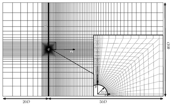
Figure 1.
Computational mesh in the plane. The inset details the mesh in the vicinity of circular cylinder and the top slit.
The resolution/grid-independence study is carried out without flow actuation at to find the best mesh in terms of computational burden while keeping reasonable accuracy in terms of global parameters. Six different meshes are studied for this purpose with the in-plane polynomial expansion of order maintained inside each element and the element count in the plane changing as shown in Table 1. Meshes with lesser in-plane resolution, such as , underpredict the St, , and , while they overpredict the . Increasing the element count in the leads to a great convergence of global parameters; however, a balance between computational effort and accuracy of results is also required. As the percentage variation in global parameters is smallest between and , was used for the remainder of the work. The maximum evaluated on the cylinder surface for is 0.9.

Table 1.
Global flow parameters for convergence study alongside planner mesh resolution i.e., .
Figure 2 indicates the distribution over the circular cylinder surface at , together with the numerical results of Singh and Mittal [19]. Both results demonstrate the highest value at the front stagnation point, which gradually decreases as the flow accelerates along the surface in the downstream direction. The flow subsequently faces an adverse pressure gradient, which enforces flow separation as the flow convects further downstream. Both curves display excellent agreement in terms of values and functional shape.
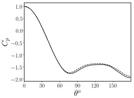
Figure 2.
Mean pressure coefficient distribution (continuous line) over the circular cylinder surface at . Numerical results of [19] (dashed line) are also shown at the coincident .
Flow over a circular cylinder is actuated via blowing and suction from the slits at at on top and bottom surfaces. The forcing is symmetric at the wake centerline, and time-dependence is introduced at , where is the von-Kármán vortex-shedding frequency. The forcing is implemented in the form of a Gaussian profile in the crossflow plane, as follows
where , A, , , , and t are the forcing velocity in the streamwise-crossflow plane, forcing amplitude, central angle of the slot at the azimuthal location and the, slot width, excitation frequency, and advective time respectively. In unsteady configurations, the force is symmetric at the wake centre plane. Figure 3 depicts a typical forcing sketch.
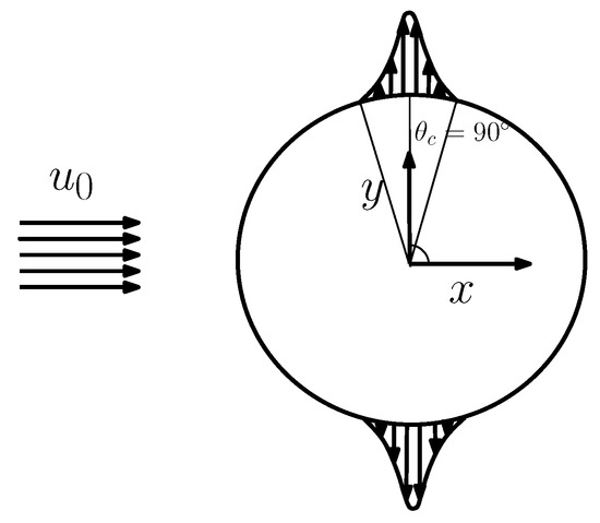
Figure 3.
A sketch depicting the in-phase actuation of flow over a circular cylinder in the cross-flow plane.
3. Wake Dynamics of Flow under Time-Dependent Actuation
The flow behind a circular cylinder features a perfectly periodic behavior in the two-dimensional flow regime. The onset of three-dimensional flow regime brings irregular dynamics in the wake, and this irregularity continues to build with the increase in . At the dynamics are already dominated by chaotic behaviour, even if the flow is computationally forced to remain two-dimensional. However, when the cylinder flow is actuated at twice the natural vortex shedding frequency, the wake dynamics transform from the chotic state to perfectly periodic state through inverse-period-doubling bifurcation with increases in the forcing amplitude, as shown in Figure 4.
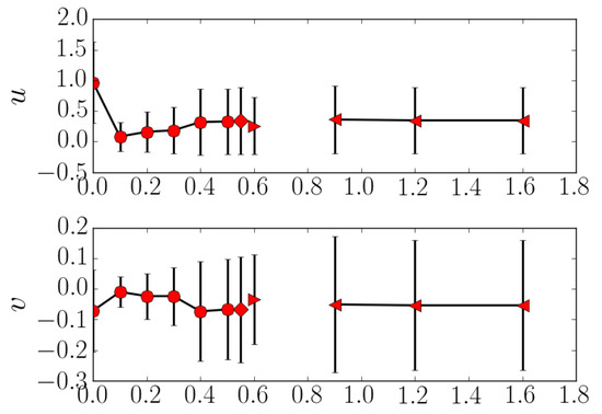
Figure 4.
Bifurcation diagram of flow past a circular cylinder actuated at twice the natural vortex-shedding frequency. The horizontal and vertical velocity components evaluated at with forcing amplitude along shown along the . Symbols denote: chaotic solution (circle), period-4 orbit (diamond), period-2 orbit (right triangle), and the periodic solution (left triangle). Vertical bars demonstrate fluctuation amplitude.
3.1. Chaos
The wake flow of circular cylinder displays a chaotic trend at for both the baseline case and the actuated case at . Chaos exhibits mitigation with increases in forcing amplitude, as shown in Figure 4. In the bifurcation diagram, streamwise and crossflow velocities evaluated at probe are plotted against forcing amplitude to denote different flow states at varying values of forcing amplitude. The probe location lies in the shear layer passage, separated from the cylinder surface, in order to register the velocity fluctuation corresponding to the wake trend. In principle, probe location could lie anywhere in the near wake of the cylinder. The dynamics were found to be dominated by chaos for , with a gradual decrease in the level of chaos with increasing forcing amplitude. The critical point for the onset of the inverse-period-doubling cascade has not been examined in this work.
To visualize the dynamics behind a circular cylinder, flow trajectories are projected on the (u, ) and (v, ) planes evaluated at in the computational domain, where u, v, and are the streamwise, crossflow velocity components and lift coefficient, respectively. Spectra of the time-series are shown on the left panels of Figure 5 for the baseline (a) and actuated with (b) cases, respectively. The higher degree of chaos was found to exist in the baseline case compared to the actuated case at . A Poincaré section was defined to determine the degree of chaos by setting and . A more disordered distribution of open circles within the phase space indicates a higher degree of chaos, whereas closely packed open circles in a relatively smaller region of phase space represent a lower degree of chaos. Higher chaos can also be observed from the spectrum of the time traces of the signal, with the highest peak being representative of natural vortex-shedding frequency St , while the width of the corresponding peak represents the equivalent degree of chaos (see right panels in Figure 5).
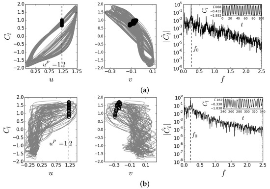
Figure 5.
Wake dynamics of baseline and actuated cases alongside phase map projection on the (u, ) and (v, ) planes. Open circles indicate crossings of a Poincaré section set as and . Spectra of the time traces are indicated in the right figures with the corresponding time series in the insets. (a) Uncontrolled case and (b) controlled case with .
3.2. Inverse Period Doubling Cascade
The transition in flow state from mild chaos to perfectly periodic state takes place between through inverse period-doubling cascade. In this work, we report period-4 state of actuated case with the appearance of four crossings, each having the period four time as the fundamental time period.
The spectrum of the time-series under fluidic actuation at is shown in Figure 6a, where the highest peak at non-dimensional frequency corresponds to the fundamental frequency with the corresponding fundamental period of . By quasi-statically reducing the forcing amplitude, the periodic solution transforms to a period-2 solution, characterized by the appearance of two crossings shown by a circle and a diamond, as indicated in Figure 6b at . This is further substantiated by the appearance of a subharmonic peak at in the spectrum of time series; see Figure 6b. The solution shows four crossings at , identified by circle, left-triangle, right-triangle, and diamond symbols, respectively, which is characteristic of a period-4 solution. The spectrum of time-series presents the highest peak at , accompanied by subharmonic peaks at and ; see Figure 6c.
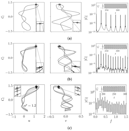
Figure 6.
Period-doubling cascade of two-dimensional controlled case at explained by phase map projection on the (u, ), (v, ) planes, and spectrum of the time series. The symbols denote the crossings of the Poincaré section defined by and . (a) periodic solution (b) period-2 solution and (c) period-4 solution.
It is interesting to investigate the evolution of flow topology in the cylinder wake as A is quasi-statically increased/decreased. Figure 7 demonstrates the evolution of a vortex-shedding cycle (periodic solution) of flow past a circular cylinder forced at with in the form of snapshots taken at equally spaced time intervals within a time period T.Snapshot was taken at the crossing shown in Figure 6a. The wake topology of flow forced at a high value of A is quite different from a typical von-Kármań vortex-shedding topology and is dominated by the shedding of four vortices during the course of a periodic solution. While the vortices from the surface of the cylinder are shed sequentially in pairs, the vortices shed from the top surface are merged into a single vortex further downstream of the wake, displaying a typical configuration, where P and S stand for a vortex-pair and a single vortex, respectively. The P lies above the wake centerline, while S remains below it, as shown in Figure 7. At , the leading vortex from the bottom surface has already been shed, while the following one is about to leave the bottom surface, and these two vortices are connected with a braid-like region. Further downstream, previously shed vortices from the top surface are merging. These merging vortices are now completely mixed, feature a single vortex and present a P-configuration at . Moreover, both vortices from the bottom surface are already shed while the first vortex from the top surface is in the process of shedding. At , the vortices are convected further downstream and a pair with negative-sign vorticity is about to shed. When the negative-sign vortices are completely shed, they start to merge as they are convected downstream at , and this process continues.
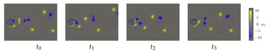
Figure 7.
Spanwise-vorticity field evolution () of the periodic orbit, evenly spaced along a full period T. Snapshots taken from the instant when flow crosses the Poincaré section, defined by and , corresponding to Figure 6a. Snapshot evenly spaced such that , , and .
The flow topology in terms of -field for the period-2 solution corresponding to Figure 6b is shown in Figure 8 in terms of equally spaced snapshots between the transition from first crossing to the next: -snapshot corresponds to the crossing denoted by a circle, while the -snapshot corresponds to a crossing shown by a diamond; see Figure 6b. The flow topology remains, essentially, the configuration with P above the wake centerline and S below the wake centerline. The key factor in triggering the period-2 solution is a small positive-sign vorticity blob occurring between the two-bigger positive-sign vortices just downstream of the cylinder base; see and instants in Figure 8. During the course of flow trajectory from a crossing labeled by circle to a crossing denoted by a diamond, the small blob is connected to a succeeding positive-signed vortex as the succeeding positive-signed vortex is shed and convected downstream in the wake, see in Figure 8, and finally merged into a single vortex as it moves further downstream along the wake; see in Figure 8. Contrary to the flow from a crossing via circle to diamond, the small positive-signed vortex blob now connects to the leading main positive-signed vortex at and is completely merged at . The flow topology finally maps to the snapshot after evolving through and ; see Figure 8.
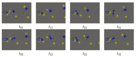
Figure 8.
Spanwise-vorticity field evolution () of the period-2 orbit. Snapshots taken from the instant when flow crosses the Poincaré section, defined by and , corresponding to Figure 6b. Snapshots are evenly spaced between the transition from crossing labeled with a circle to that labeled with a diamond and then the other way round. Colour coding as for Figure 7.
Figure 9 depicts the wake topology corresponding to dynamics projected in the phase plane in Figure 6a at . , , , and time-instants correspond to the snapshots taken at crossing i.e., circle, left-triangle, right-triangle and diamond indicating crossings, respectively. A fundamental change in the configuration was observed in period-4 orbit compared to period-2 and periodic orbits, i.e., P lies below the wake centerline and S is spotted above it contrary to later cases. In period-4, positive-signed vortices are merged during the dynamics from one crossing to the other, which is not the case for period-2 and periodic flows.
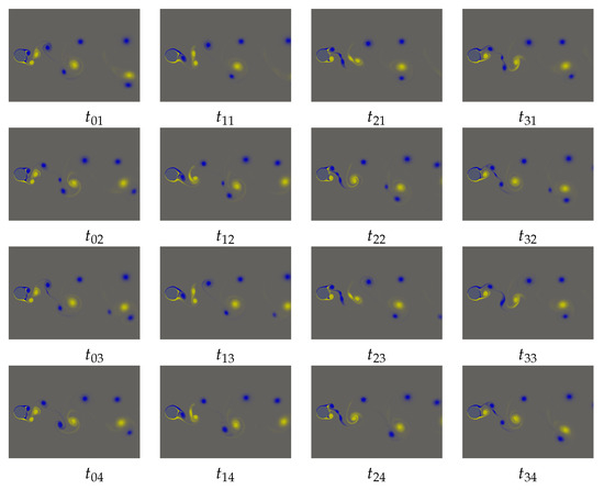
Figure 9.
Spanwise-vorticity field evolution () of the period-4 orbit. Snapshots taken from the instant when flow crosses the Poincaré section, defined by and , corresponding to Figure 6c. Snapshots are evenly spaced between the transitions from crossing labeled with circle to the next until it gets back to circle. Colour coding as for Figure 7.
It is also intriguing to see how the wake evolves over the course of a period-4 cycle. The evolution of vortex-shedding from one crossing to the next is equally spaced into four time instants. During the first transition, a positive-signed vortex pair sheds and merges into a single vortex during evolution from to . Another important feature of the period-4 wake is the appearance of a negatively signed small vortex located between the negatively signed shed vortices, which remains a distinguishable vortex further downstream of the wake. In the second transition from a left-triangle crossing to right-triangle crossing, the -configuration remains unaltered. However, the small negatively-signed vortex between shedding and being about to shed becomese visible at instant, and finally merges with the succeeding negatively-signed vortex after convecting downstream at and . The same small vortex in the next transitional phase merges with the leading vortex, as shown in and . In the last transition, which ultimately completes the period-4 cycle, a small negatively-signed vortex merges with the succeeding negatively signed vortex; see and in Figure 9.
4. Conclusions
Active flow control in the form of blowing and suction, spanwise, independent and time-dependent, at twice the natural vortex-shedding frequency, from the top and bottom slits of a circular cylinder, is implemented at Reynolds number 2000 to investigate flow dynamics. The wake dynamics are observed to undergo a transition from a mildly chaotic to perfectly periodic state when forcing amplitude is quasi-statically increased. The physical mechanism for the transitional flow from a chaos to periodic state is governed by the inverse period-doubling cascade.
Author Contributions
Conceptualization, W.S., F.M. and M.M.A.; methodology, W.S. and F.M.; software, W.S.; validation, W.S., F.M.; formal analysis, W.S.; investigation, W.S.; resources, F.M., M.M.A.; data curation, W.S., F.Z.; writing—original draft preparation, W.S., F.Z.; writing—review and editing, F.M. and M.M.A.; visualization, W.S.; supervision, F.M. and M.M.A.; project administration, F.M.; funding acquisition, F.M. and M.M.A. All authors have read and agreed to the published version of the manuscript.
Funding
This work has been financed by the Spanish and Catalan Governments under grants FIS2016-77849-R and 2017-SGR-00785, respectively. The authors also thankfully acknowledge the computer resources at MareNostrum and Calendula accessed through grants RES-FI-2017-2-0020 and RES-FI-2017-3-0009, respectively.
Institutional Review Board Statement
Not applicable.
Informed Consent Statement
Not applicable.
Data Availability Statement
Not applicable.
Conflicts of Interest
The authors declare no conflict of interest.
References
- Feigenbaum, M.J. Quantitative universality for a class of nonlinear transformations. J. Stat. Phys. 1978, 19, 25–52. [Google Scholar] [CrossRef]
- Chen, M.; Jia, L.B.; Wu, Y.F.; Yin, X.Z.; Ma, Y.B. Bifurcation and chaos of a flag in an inviscid flow. J. Fluid Struc. 2014, 45, 124–137. [Google Scholar] [CrossRef] [Green Version]
- An, B.; Bergada, J.M.; Mellibovsky, F. The lid-driven right-angled isosceles triangular cavity flow. J. Fluid Mech. 2019, 875, 476–519. [Google Scholar] [CrossRef]
- Ruelle, D.; Takens, F. Note Concerning Our paper: “On the Nature of Turbulence”; Springer: Berlin/Heidelberg, Germany, 1971; Volume 23, pp. 343–344. [Google Scholar]
- Manneville, P.; Pomeau, Y. Different ways to turbulence in dissipative dynamical systems. Physica D 1980, 1, 219–226. [Google Scholar]
- Kelly, R.; Hu, H.C. The onset of Rayleigh–Bénard convection in non-planar oscillatory flows. J. Fluid Mech. 1993, 249, 373–390. [Google Scholar] [CrossRef]
- Karniadakis, G.E.; Triantafyllou, G.S. Three-dimensional dynamics and transition to turbulence in the wake of bluff objects. J. Fluid Mech. 1992, 238, 1–30. [Google Scholar] [CrossRef]
- Heinrichs, R.; Ahlers, G.; Cannell, D.S. Traveling waves and spatial variation in the convection of a binary mixture. Phys. Rev. A 1987, 35, 2761. [Google Scholar] [CrossRef] [PubMed]
- Zhang, J.; Liu, N.S.; Lu, X.Y. Route to a chaotic state in fluid flow past an inclined flat plate. Phys. Rev. E 2009, 79, 045306. [Google Scholar] [CrossRef] [PubMed]
- Sarwar, W.; Bergadà, J.M.; Mellibovsky, F. Onset of temporal dynamics within a low reynolds-number laminar fluidic oscillator. Appl. Math. Model. 2021, 95, 219–235. [Google Scholar] [CrossRef]
- Abdelhamidab, T.; Alama, M.M.; Islamc. Heat transfer and flow around cylinder: Effect of corner radius and Reynolds number. Int. J. Heat Mass Transfer 2021, 171, 121105. [Google Scholar]
- Henderson, R.D.; Barkley, D. Secondary instability in the wake of a circular cylinder. Phys. Fluids 1996, 8, 1683–1685. [Google Scholar] [CrossRef] [Green Version]
- Bai, H.; Alam, M.M. Dependence of square cylinder wake on Reynolds number. Phys. Fluids 2018, 30, 015102. [Google Scholar] [CrossRef]
- Barkley, D.; Henderson, R. Three-dimensional Floquet stability analysis of the wake of a circular cylinder. J. Fluid Mech. 1996, 322, 215–241. [Google Scholar] [CrossRef] [Green Version]
- Derakhshandeh, J.; Alam, M.M. A review of bluff body wakes. Oce. Eng. 2019, 182, 475–488. [Google Scholar] [CrossRef]
- Mansy, H.; Yang, P.; Williams, D. Quantitative measurements of three-dimensional structures in the wake of a circular cylinder. J. Fluid Mech. 1994, 270, 277–296. [Google Scholar] [CrossRef]
- Sarwar, W.; Mellibovsky, F. Characterization of three-dimensional vortical structures in the wake past a circular cylinder in the transitional regime. Phys. Fluids 2020, 32, 074104. [Google Scholar] [CrossRef]
- Cantwell, C.; Moxey, D.; Comerford, A.; Bolis, A.; Rocco, G.; Mengaldo, G.; De Grazia, D.; Yakovlev, S.; Lombard, J.E.; Ekelschot, D.; et al. Nektar++: An open-source spectral/hp element framework. Comp. Phys. Commu. 2015, 192, 205–219. [Google Scholar] [CrossRef] [Green Version]
- Singh, S.; Mittal, S. Flow past a cylinder: Shear layer instability and drag crisis. Int. J. Num. Meth. Fluids 2005, 47, 75–98. [Google Scholar] [CrossRef] [Green Version]
Publisher’s Note: MDPI stays neutral with regard to jurisdictional claims in published maps and institutional affiliations. |
© 2021 by the authors. Licensee MDPI, Basel, Switzerland. This article is an open access article distributed under the terms and conditions of the Creative Commons Attribution (CC BY) license (https://creativecommons.org/licenses/by/4.0/).