Article

DYN3D and CTF Coupling within a Multiscale and Multiphysics Software Development (Part I)

1
School of Engineering, University of Liverpool, Liverpool L69 3GH, UK
2
Institute of Innovation, Helmholtz Zentrum Dresden Rossendorf, 01328 Dresden, Germany
3
EDF Energy, Gloucester GL4 3R, UK
*
Author to whom correspondence should be addressed.
Energies 2021, 14(16), 5060; https://doi.org/10.3390/en14165060
Submission received: 16 May 2021 / Revised: 31 July 2021 / Accepted: 10 August 2021 / Published: 17 August 2021
(This article belongs to the Topic Power System Modeling and Control)

Abstract

:
Understanding and optimizing the relation between nuclear reactor components or physical phenomena allows us to improve the economics and safety of nuclear reactors, deliver new nuclear reactor designs, and educate nuclear staff. Such relation in the case of the reactor core is described by coupled reactor physics as heat transfer depends on energy production while energy production depends on heat transfer with almost none of the available codes providing full coupled reactor physics at the fuel pin level. A Multiscale and Multiphysics nuclear software development between NURESIM and CASL for LWRs has been proposed for the UK. Improved coupled reactor physics at the fuel pin level can be simulated through coupling nodal codes such as DYN3D as well as subchannel codes such as CTF. In this journal article, the first part of the DYN3D and CTF coupling within the Multiscale and Multiphysics software development is presented to evaluate all inner iterations within one outer iteration to provide partially verified improved coupled reactor physics at the fuel pin level. Such verification has proven that the DYN3D and CTF coupling provides improved feedback distributions over the DYN3D coupling as crossflow and turbulent mixing are present in the former.

1. Introduction

Globally, the use of nuclear power has expanded to 31 countries with 443 nuclear reactors operating and 52 nuclear reactors under construction, which have made nuclear power become the second largest source of carbon free power [1]. Around 80% of the nuclear reactors are LWR (Light Water Reactor) which provide improved economics and safety when compared to previous nuclear reactors [2] by: Simplifying the nuclear reactor design as there is no distinction between the coolant and moderator. Decreasing the nuclear reactor size as the high moderation allows yielding a certain power density while using less fuel and the high cooling allows to keep a certain power density, while using a compact design. Increasing the nuclear reactor stability as the high moderation decreases with high power leading to a reduction in the criticality and the high cooling increases with the high fluid density, which leads to a reduction in the temperatures. Increasing the nuclear reactor efficiency as the high moderation allows achieving a high fuel burn up or utilisation and the high cooling allows to achieve a high heat conductance.
In the UK, there is currently great interest in LWR as can be observed through the different projects that are being funded across the country including both the construction of new nuclear reactors to provide power to the future generations [3] as well as the development of a nuclear innovation programme [4] to improve the economics and safety of nuclear reactors, deliver new nuclear reactor designs, and educate nuclear staff. Large nuclear reactors currently considered include the EPR (European Pressurised Reactor) by Areva for HPC (Hinkley Point C) and Sizewell C [5], with each nuclear reactor providing 1650 MW of power for a period of 60 years. Small nuclear reactors currently considered include the AMR (Advanced Modular Reactor) by Rolls Royce for remote sites [6] with each nuclear reactor providing 440 MW of power for a large period. The nuclear innovation programme was approved by BEIS (Department of Business, Energy and Industrial Strategy) in 2016 with support from different academic and industrial partners across the UK, which will invest over 460 million pounds over the following years. It is structured into advanced fuels, advanced manufacturing and materials, advanced reactor design, and recycle and reprocess, providing innovation across the whole nuclear fuel cycle. A project within the advanced reactor design known as DRD (Digital Reactor Design) [7] is being developed by different academic and industrial partners across the UK to deliver virtual replicas of nuclear reactors, providing innovation from a computational perspective.
It is important to understand the relation between components or physical phenomena in a LWR to improve the economics and safety of nuclear reactors, deliver new nuclear reactor designs, and educate nuclear staff by acknowledging the physical phenomena that take place [8,9] including the energy production analysed using neutronics, the heat and mass transfer analysed using thermal hydraulics, the fuel behaviour analysed using thermo-mechanics, and risks analysed using probability analysis. The neutronics, thermal hydraulics, thermo mechanics, and probability analysis are said to be coupled to each other in the following ways: The power production in the nuclear reactor depends both on the heat and mass transfer through the fuel, moderator temperatures, and the moderator density, leading to reactivity feedback as well as on the fuel behaviour through the fuel burnup, which leads to cross section changes. The heat and mass transfer in the nuclear reactor depends both on the power production through the fission chain reaction, leading to heat deposition as well as on the fuel behaviour through the fuel burnup, which leads to thermal conductivity and specific heat changes. The fuel behaviour in the nuclear reactor depends both on the power production through irradiation, leading to fuel integrity changes, and on the heat and mass transfer through the fuel temperature, which also leads to fuel integrity changes. The risks in the nuclear reactor depend both on the power production through the heat deposition, which may lead to melting in the fuel as well as on the heat and mass transfer through the clad temperature, which may lead to DNB (Departure from Nucleate Boiling).
It is important to optimize the relation between components or physical phenomena in a LWR to improve the economics and safety of nuclear reactors, deliver new nuclear reactor designs, and educate nuclear staff by simulating the physical phenomena that take place [10,11,12] including the neutronics simulated using lattice, neutron transport, and nodal codes [13,14,15,16,17,18,19], the thermal hydraulics simulated using system, nodal, subchannel and CFD codes [17,18,19,20,21,22], the thermo mechanics simulated using fuel performance codes [23,24,25], and the probability analysis simulated using risk assessment codes [26]. None of the mentioned codes provide full coupled reactor physics at the fuel pin level due to computational limitations that existed during the times when these codes were originally developed, which resulted from the geometry complexity, the large number of fuel pins, the coupled physical phenomena, and the large simulation times. Only nodal codes provide simplified coupled reactor physics at the fuel assembly level after performing fuel assembly homogenisation, where average fuel assembly cross sections are derived from fuel pin cross sections. Some nodal codes provide simplified coupled reactor physics at the fuel pin level after performing fuel pin reconstruction, where fuel pin power distributions are derived from additional shaping functions. Both fuel assembly homogenisation and fuel pin power reconstruction are limited in terms of coupling due to the loss of coupled physical phenomena, which has led to safety parameters being based on simplified coupled reactor physics at the fuel assembly level, rather than being based on full coupled reactor physics at the fuel pin level, resulting in the imposition of extra safety margins both in nuclear reactor operation and design.
Current state-of-the-art simulation codes that aim to provide full or improved coupled reactor physics at the fuel pin level for LWR include NURESIM (Nuclear Reactor Simulator) [27,28] and CASL (Consortium for Advanced Simulation of LWR) [29,30]. NURESIM is a development by Euratom, that aimed to provide full coupled reactor physics at the fuel pin level, although computational limitations led to the development of a simplification known as SALOME [31], which has the aim of providing improved coupled reactor physics at the fuel pin level by using lattice codes such as APOLLO2 [32] to provide the fuel assembly homogenisation required in nodal codes. Nodal codes such as COBAYA3, CRONOS2 [33], and DYN3D (Dynamical 3 Dimensional) [34] provide simplified coupled reactor physics at the fuel assembly level and the fuel pin power reconstruction required for simplified coupled reactor physics at the fuel pin level as well as the boundary conditions used in other codes. CFD and subchannel codes such as TRIO_U [35], SUBCHANFLOW [36], FLICA4 [37], NEPTUNE [38], and TransAT [39] provide full thermal hydraulics at the fuel pin level and the boundary conditions used in other codes. System codes such as CATHARE (Code for Analysis of Thermal Hydraulics during an Accident of Reactor and Safety Evaluation) [40] and ATHLET (Analysis of Thermal Hydraulics of Leaks and Transients) [41] provide simplified thermal hydraulics at the nuclear power plant level and the boundary conditions used in other codes. Finally, fuel performance codes such as DRACCAR [42] and SCANAIR (Systems of Codes for Analysing Reactivity Initiated Accidents) [43] provide full thermo mechanics at the fuel pin level and the boundary conditions used in other codes. CASL is a development by the USDE (United States Department of Energy), that aimed to provide improved coupled reactor physics at the fuel pin level, although solution requirements led to a new development known as CASL-Advanced [44], which has the aim of providing full coupled reactor physics at the fuel pin level by using spectral codes such as ORIGEN [45] and SCALE [46] to provide the fuel pin cross sections required in neutron transport codes. Neutron transport codes such as MPACT [47], INSILICO [48], and SHIFT [49] provide full neutronics at the fuel pin level and the boundary conditions used in other codes. CFD and subchannel codes such as CTF (Coolant Boiling in Rod Arrays Three Flow Fields) [50] and HYDRA-TH [51] provide full thermal hydraulics at the fuel pin level and the boundary conditions used in other codes. System codes such as RELAP5 (Reactor Excursion and Leak Analysis Program) [52] provide simplified thermal hydraulics at the nuclear power plant level and the boundary conditions used in other codes. Finally, fuel performance codes such as BISON provide full thermo mechanics at the fuel pin level and the boundary conditions used in other codes. SALOME is not adequate for the UK as it neglects full coupled reactor physics at the fuel pin level with lattice codes only being used to provide the fuel assembly homogenisation required in nodal codes, while CASL-Advanced is not affordable by the UK as it extends introduces computational limitations through the extension of full coupled reactor physics at the fuel pin level to all the reactor core. All the codes can be found classified in the Appendix A.
Another project within the nuclear innovation programme between NURESIM and CASL known as Multiscale and Multiphysics Software Development is a development by the UOL (University of Liverpool) [53] which has the aim of providing both improved and full coupled reactor physics at the fuel pin level for LWR while remaining both adequate for the UK as well as affordable by the UK by using spectral codes such as SCALE [15,54] to provide both the fuel pin cross sections required in neutron transport codes and the fuel assembly homogenisation required in nodal codes. Nodal codes such as DYN3D [17,34] provide simplified coupled reactor physics at the fuel assembly level and the fuel pin power reconstruction required for simplified coupled reactor physics at the fuel pin level as well as the boundary conditions used in other codes. Neutron transport codes such as LOTUS [14,55] (Liverpool Transport Solver) provide full neutronics at the fuel pin level and the boundary conditions used in other codes. Subchannel codes such as CTF [20,50] provide full thermal hydraulics at the fuel pin level and the boundary conditions used in other codes. System codes such as RELAP5 [52] provide simplified thermal hydraulics at the nuclear power plant level and the boundary conditions used in other codes. Finally, fuel performance codes such as ENIGMA [56] provide full thermo mechanics at the fuel pin level and the boundary conditions used in other codes. This Multiscale and Multiphysics Software Development will be adequate for the UK as it provides full coupled reactor physics at the fuel pin level with neutron transport codes being used to provide full neutronics at the fuel pin level and will be affordable by the UK as it reduces computational limitations through the restriction of full coupled reactor physics at the fuel pin level only to the fuel assemblies of interest in the reactor core.
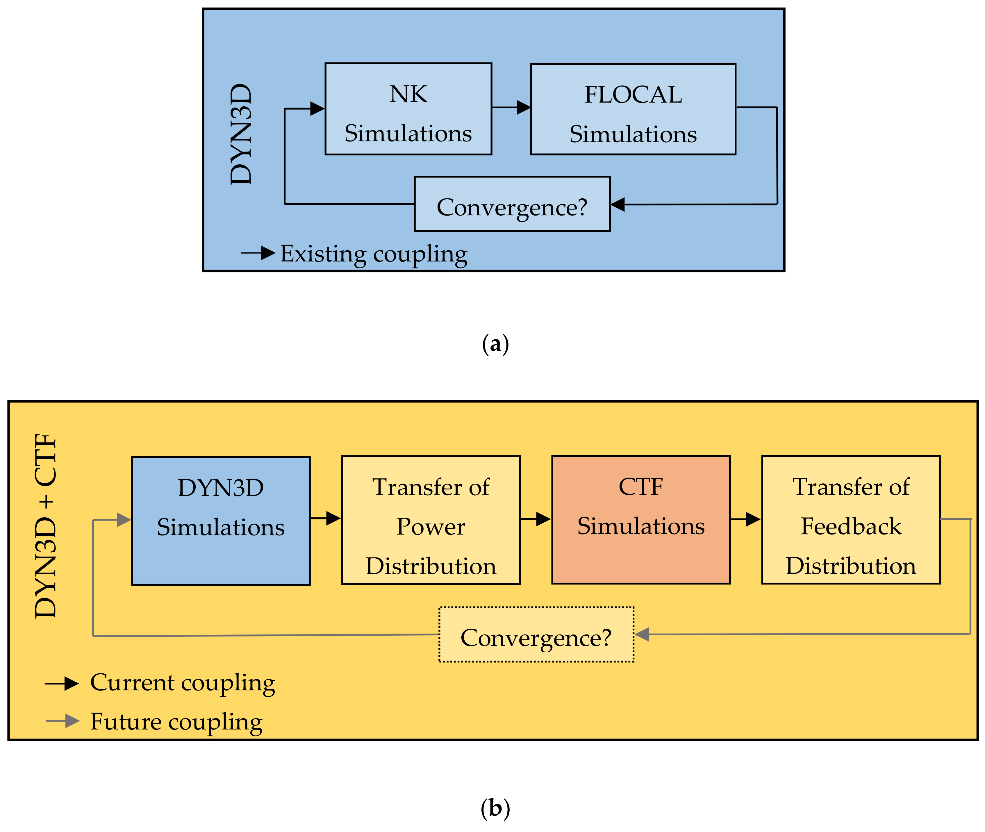
The coupling between any two of the mentioned codes [57,58] within the Multiscale and Multiphysics Software Development involves several steps such as simulations using the first code, the transfer of data from the first code to the second code, simulations using the second code, and finally the transfer of data from the second code to the first code. Each of these coupling steps conform to an inner iteration while all coupling steps conform to an outer iteration with outer iterations being run on a cyclic basis until some convergence criterion is verified, which usually consists of a comparison between the current and the previous outer iterations. The coupling between any two of the mentioned codes can be external, internal, and in parallel, which implies different levels of coupling integration [59]. In external coupling, both codes are run separately, and the transfer of data is done using additional scripts, apart from both codes. In internal coupling, both codes are run separately, and the transfer of data is done using additional internal libraries within the codes themselves. In parallel coupling, both codes are run simultaneously, and the transfer of data is done using additional internal libraries within the codes themselves. The mentioned types of coupling between any two of the mentioned codes within the Multiscale and Multiphysics Software Development can be observed in Figure 1.
The aim consists of coupling the nodal code DYN3D and the subchannel code CTF within the Multiscale and Multiphysics Software Development to provide improved coupled reactor physics at the fuel pin level [53]. The previous objective to achieve this aim consisted of CTF and FLOCAL (thermal hydraulics module of DYN3D) thermal hydraulics validations and verifications [20] that were performed to evaluate the accuracy and methodology available to provide thermal hydraulics at the fuel pin level. CTF was observed to provide high accuracy when compared to other fluid dynamics codes, allowing the justification as to why CTF was chosen to provide full thermal hydraulics at the fuel pin level in this Multiscale and Multiphysics Software Development. CTF was observed to provide a wide range of crossflow and turbulent mixing methods while FLOCAL was observed to provide only the no crossflow method, allowing us to justify why CTF should be used to provide full thermal hydraulics at the fuel pin level in cases with more heterogeneous power distributions and why FLOCAL should be used to provide simplified thermal hydraulics at the fuel pin level in cases with more homogeneous power distributions in this Multiscale and Multiphysics Software Development.
The current objective in achieving this aim consists of the first part of the DYN3D and CTF coupling, which was performed to evaluate all inner iterations within an outer iteration to provide partially verified improved coupled reactor physics at the fuel pin level, where the NK (neutronics module of DYN3D) and FLOCAL coupling within DYN3D provide simplified coupled reactor physics at the fuel pin level that can be used as a reference. This evaluation allows one to show through external coupling how the transfer of power distributions from DYN3D to CTF and how the transfer of feedback distribution from CTF to DYN3D takes place as well as justify through the thermal hydraulics when the DYN3D and CTF coupling rather than just DYN3D should be used to provide improved coupled reactor physics at the fuel pin level. This second journal article therefore covers the DYN3D and CTF coupling inner iterations within one outer iteration verification to provide partially verified improved coupled reactor physics at the fuel pin level, while the DYN3D and CTF coupling outer iterations within the convergence criteria verification to provide fully verified improved coupled reactor physics at the fuel pin level will be covered in the next journal article.
Simplified coupled reactor physics at the fuel assembly level in DYN3D are available after performing fuel assembly homogenisation; additionally, simplified coupled reactor physics at the fuel pin level in DYN3D are available after performing fuel pin reconstruction. Another alternative for simplified coupled reactor physics at the fuel pin level in DYN3D is available by directly simulating fuel pin scaled nodes using fuel pin cross sections instead of simulating fuel assembly scaled nodes using fuel assembly cross sections. Full thermal hydraulics at the fuel pin level in CTF are available by default. Nevertheless, the simplified coupled reactor physics at the fuel pin level in DYN3D are limited in terms of neutronics by neutron diffusion and limited in terms of thermal hydraulics by the lack of crossflow and turbulent mixing. However, the improved coupled reactor physics at the fuel pin level in the DYN3D and CTF coupling are only limited in terms of neutronics by neutron diffusion but complemented in terms of thermal hydraulics by the wide range of crossflow and turbulent mixing.
The structure of this journal article consists of several parts. First, a DYN3D description comprehending general features, updates, etc. [60,61] was performed to present the first code used in the coupling inner iterations within one outer iteration verification. Second, a CTF description comprehending general features, updates, etc. [62,63] was undertaken to present the second code used in the coupling inner iterations within one outer iteration verification. Third, the specifications description covering the KAIST (Korean Advanced Institute of Science and Technology) benchmark [64] was performed to present the data used in the coupling inner iterations within one outer iteration verification. Fourth, the models description for the simulation of the benchmark was performed to present its implementation into the coupling inner iterations within one outer iteration verification. Fifth, the scripts description comprehending the transfer of power distributions from DYN3D to CTF as well as the transfer of feedback distributions from CTF to DYN3D was performed to present the coupling inner iterations within one outer iteration verification.
The results and analysis obtained for the DYN3D and CTF coupling inner iterations within one outer iteration verification through the KAIST benchmark were comprehended by DYN3D coupling to DYN3D and CTF coupling comparisons. Tests presented include results for the fluid density feedback, fluid temperature feedback, fuel temperature feedback, and the pressure drop feedback in 17 × 17 fuel assemblies with guide tubes and with or without burnable absorber fuel pins. All these magnitudes were chosen to analyse the DYN3D and CTF coupling in nuclear reactors from a thermal hydraulics perspective. It can be observed how this comparison allows one to show the DYN3D and CTF coupling compared to the DYN3D coupling.
Conclusions regarding the DYN3D and CTF coupling inner iterations within one outer iteration verification were made to corroborate the second objective with the aim of providing the DYN3D and CTF coupling within the Multiscale and Multiphysics Software Development, which was fulfilled by verifying the DYN3D and CTF coupling inner iterations within one outer iteration. Finally, future work that remains is presented to address the last objective with the aim of providing the DYN3D and CTF coupling within the Multiscale and Multiphysics Software Development.

2. Codes Used in the Verification

As previously mentioned, DYN3D and CTF were the codes that were selected as they are widely used in both academia and the industry, and hence their main features, version updates, equations, and solution approach are described in the next two subsections.

2.1. DYN3D Nodal Code

DYN3D [60,61,65] was developed using FORTRAN 90 in the early 1990s by FZD (Forschung Zentrum Dresden) and has been continuously updated. It is a LWR-VVER (square and hexagonal geometries) coupled reactor physics nodal code developed for the purpose of studying general nuclear reactor behaviour. Capabilities such as 3D modelling have resulted in the code being widely used for LWR-VVER steady and transient state analysis. In terms of neutronics, it uses the neutron diffusion approach with two energy groups complemented by nodal expansion methods such as nodal expansion, SP3 (only square geometry) HEXNEM1-2 (only hexagonal geometry), ADF (Assembly Discontinuity Factors), and pin power reconstruction. In terms of thermal hydraulics, it uses a none crossflow, or turbulent mixing 2-fluid approach complemented by heat transfer models such as two phase heat transfer and interphase heat transfer.
DYN3D-MG is an updated version of DYN3D developed by HZDR (Helmholtz Zentrum Dresden Rossendorf). Updates include implementing the neutron diffusion approach with multi energy groups, improving the calculation of reactivity by inverse point kinetics as performing the calculation of dynamical reactivities, implementing the Pernica departure from nucleate boiling correlation, and improving the calculation of boric acid transport by using the particle in cell method.
A reactor core or smaller system can be modelled in DYN3D and is represented through a set of nodes that generally conform to channels. The neutron diffusion N energy groups and M delayed neutron precursor modelling approach is applied to the set of nodes with each energy group being modelled through its own neutron diffusion equation and each delayed neutron precursor group being modelled through its own concentration equation. The none crossflow or turbulent mixing two fluid (liquid, vapor) modelling approach is applied to the set of nodes with the fluid mixture being modelled through a set of fluid mass, fluid momentum, and fluid energy conservation equations with the vapor mass equation being treated separately. All the equations were formulated using either a cartesian or hexagonal coordinate system. These were then finally expressed in a finite difference form and solved using numerical methods. An implicit method was applied to all the equations.
Certain conditions are required to obtain a solution to the neutron diffusion and concentration equations such as including the steady or transient nature of the system to perform the calculations, acknowledging other possible external neutron sources that account for additional fast neutrons that affect the nodes neutron fluxes, determining the poisoning state of the reactor to obtain the correct contributions to the absorption cross section, and performing pin reconstruction to produce solutions at the fuel pin level in addition to the fuel assembly level.
Certain conditions are required to obtain a solution to the fluid mass, fluid momentum, and fluid energy equations such as including the steady or transient nature of the system to perform the calculations, determining the constitutive relations that relate the fluid mass, fluid momentum, and fluid energy equations for the two phases in the nodes leading to effects such as phase change, determining fluid and solid thermal and mechanical properties using tables and implemented correlations.

2.2. CTF Subchannel Code

COBRA-TF [62,63,66] was developed using FORTRAN 77 in 1980 by PNL (Pacific Northwest Laboratories, Washington, WA, USA), sponsored by the NRC (Nuclear Regulation Commission) and has been continuously updated. It is a LWR (square geometry) thermal hydraulics subchannel code developed for the purpose of studying general nuclear reactor behaviour and accident scenarios. Capabilities such as full 3D modelling have resulted in the code being widely used for LWR steady and transient state analysis. In terms of thermal hydraulics, it uses a wide crossflow and turbulent mixing two fluid, three flow field approach complemented by flow regime/heat transfer dependent models such as two phase heat transfer, interphase heat transfer and drag, entrainment, and quench front tracking.
CTF is an updated version of COBRA-TF developed and maintained by the PSU (Pennsylvania State University, Pennsylvania, PA, USA) and NCSU (North Carolina State University, Raleigh, NC, USA). Updates include changing the source code to FORTRAN 90, improving user friendliness by providing error check and free format input, assuring quality by using wide validation and verification, improving void drift, turbulent mixing, and heating models, enhancing computational efficiency by introducing new numerical methods, finally, improving the physical model and user modelling information.
Any system, apart from pressurisers, can be modelled in CTF and is represented through a matrix of mesh cells that conform to subchannels. The wide crossflow and turbulent mixing two fluid (liquid, vapor), three flow field (liquid film, liquid droplets, and vapor) modelling approach is applied to the mesh cells with each field being modelled through its own set of fluid mass, fluid momentum, and fluid energy conservation equations with the liquid and droplet fields being in thermal equilibrium between them, and hence sharing the same energy equation. The equations were formulated using either a cartesian or a simplified subchannel coordinate system. These were then finally expressed in a finite difference form and solved using numerical methods. A homogeneous equilibrium method was applied to the conservation equations known as SIMPLE (Semi Implicit Method for Pressure Linked Equations).
Certain conditions are required to obtain a solution to the fluid mass, fluid momentum, and fluid energy equations such as including the steady or transient nature of the system to perform the calculations, determining the flow regime to obtain the correct macro and micro mesh cell closure terms necessary to account for the correct collective phenomena, determining the macro mesh cell closure terms that relate the conservation equations for the same phase in different mesh cells leading to phenomena such as void drift and turbulent mixing, determining the micro mesh cell closure terms that relate the conservation equations for different phases in the same mesh cell leading to inter-phase effects such as phase change and entrainment, and determining fluid and solid thermal and mechanical properties using tables and implemented correlations.

3. Specifications Used in the Verification

As previously mentioned, the DYN3D and CTF coupling inner iterations within one outer iteration verification was performed by covering the KAIST benchmark. Hence, the specifications used in the above-mentioned are described in the following subsection.

KAIST Benchmark

The KAIST benchmark [64] is a benchmark for PWR reactor core neutronics and thermal hydraulics simulation. No experimental data or other code results are available. Tests performed include steady state 17 × 17 fuel assemblies containing fuel pins and guide tubes as well as burnable absorber pins with variation dependant axial and radial power distributions and uniform pressure losses. The KAIST benchmark has been expanded through a multi parameter variation exercise consisting of six coupling tests based on a reference PWR under general nuclear reactor behaviour, where variation of a single parameter is applied to either the total power, the inlet temperature, the outlet pressure, the inlet mass flux, or the inlet boric acid. All the data for the tests has been presented.
Specifications include the geometry, materials, spacer grids, and initial and boundary conditions [64]. The geometry is described for the 17 × 17 assemblies with or without burnable absorber pins as observed in Table 1.
The materials are described as observed in Table 2.
Spacer grids are uniform and are described as observed in Table 3.
The initial and boundary conditions are described as observed in Table 4.

4. Models and Scripts Used in the Verification

As previously mentioned, the DYN3D and CTF coupling inner iterations within one outer iteration verification were performed by simulating the KAIST benchmark in addition to using additional coupling scripts. Hence, the models and scripts used in the above-mentioned are described in the following subsections.

4.1. KAIST Benchmark

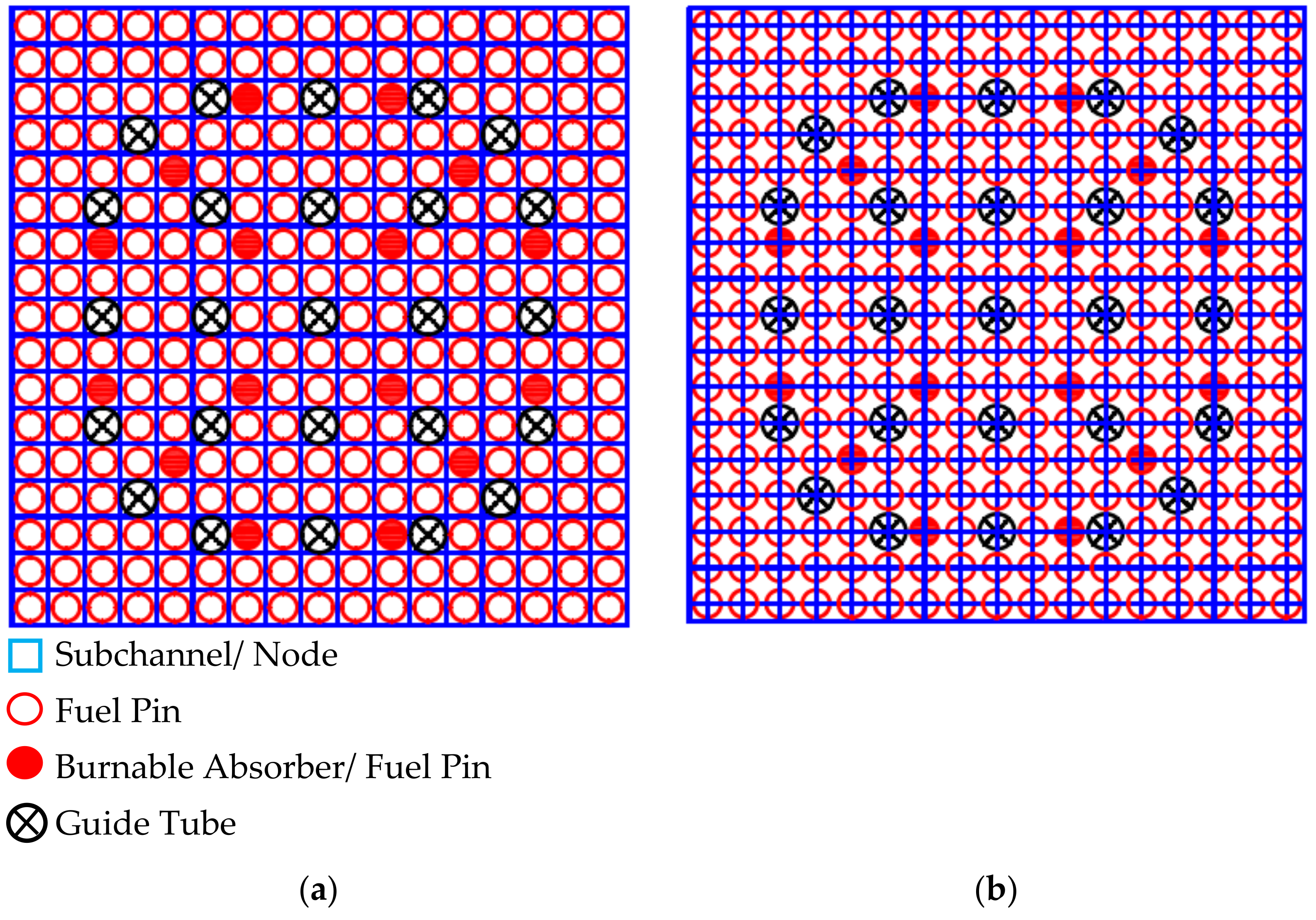
Models used in DYN3D include 289 fuel cells (fuel pin centred system) conformed by 36 uniform axial node layers along with in the case of the UOX-2 (CR) fuel assembly, 264 fuel pins, and 25 guide tubes or in the case of the UOX-2 (BA16) fuel assembly, 248 fuel pins as well as 16 burnable absorber pins, and 25 guide tubes that have been modelled in the steady state. Models used in CTF include 324 subchannels (subchannel centred system) connected in between by 612 gaps contained in one section conformed by 36 uniform axial node layers along with in the case of the UOX-2 (CR) fuel assembly, 264 fuel pins, and 25 guide tubes or in the case of the UOX-2 (BA16) fuel assembly, 248 fuel pins as well as 16 burnable absorber pins and 25 guide tubes that have been modelled in the steady state. The fuel pin centred system model in DYN3D and the subchannel centred system model in CTF for both the UOX-2 (CR) and UOX-2 (BA16) fuel assemblies can be observed in Figure 2.
Regarding the neutronics in DYN3D, two energy groups were modelled including fast and thermal energy groups according to the KAIST benchmark specifications. Steady state was achieved by division of the multiplication cross sections by the effective criticality factor as it is useful for experimental repetitions, allowing the power and the boric acid concentration to be predefined. Reflective boundary conditions have been used for any re-entering current into any of the energy groups as otherwise due to the node sizes, neutrons would escape the system. The homogenised cross sections for the fuel and burnable absorber pins and guide tubes were previously obtained using SCALE-POLARIS simulating multiple feedback parameter combinations to construct multidimensional cross section tables through which DYN3D performs interpolation, as is generally done in nodal codes. The effective criticalities for certain tests with constant thermal hydraulics feedback have been compared between DYN3D and SCALE-POLARIS, leading to similar values.
Regarding the thermal hydraulics in both DYN3D and CTF, friction pressure losses have been modelled in the case of DYN3D using Filonenko’s and Osmachkin’s [67] one phase and two phase multipliers correlation due to it being the only one available, while these have been modelled in the case of CTF using McAdam’s [68] correlation due to it being widely used in LWR analysis. Spacer grid pressure losses have been modelled in both DYN3D and CTF using a uniform pressure loss coefficient of 0.30, as estimated through previous simulations. The pressure equation has been solved in the case of DYN3D using Gaussian elimination due to it being the method available, while this has been solved in the case of CTF using the Krylov solver due to it being a method more effective than Gaussian elimination. Nucleate boiling has been modelled in the case of DYN3D using the Rassokhin and Borishaskji [69] correlation due to it being the one available, while this has been modelled in the case of CTF using the Thom [70] correlation due to it being validated for a wider pressure range than the Chen correlation. Departure from nucleate boiling has been modelled in the case of DYN3D using the Bezrukov and Astakhov (OKB-2) [71] correlation due to this one being the best available, while this has been modelled in the case of CTF using the W-3 [72,73] correlation due to it being widely used in LWR analysis. Crossflow is not available in the case of DYN3D, while this has been modelled in the case of CTF using the available CTF model. Turbulent mixing is not available in the case of DYN3D, while this has been modelled in the case of CTF using the Rogers and Rosehart correlation, which depends on an empirical correlation determined single-phase mixing coefficient and a two-phase multiplier with a value of 5.0 as well as an equilibrium weighting void drift factor with a value of 1.4 [74] due to it being the best available. Entrainment and deposition for the droplets are not available in the case of DYN3D, while these have been modelled in the case of CTF using the original CTF model due to the necessary accuracy.

4.2. DYN3D and CTF Coupling Scripts

Additional scripts have been developed using PYTHON quite recently at the UOL. These are LWR-VVER (square and hexagonal geometries) coupled reactor physics coupling scripts that were developed for the purpose of performing the DYN3D and CTF coupling within the Multiscale and Multiphysics Software Development. Capabilities such as the transfer of power distributions from DYN3D to CTF, and the transfer of feedback distribution from CTF to DYN3D as well as the output of any distribution from both codes have resulted in the additional scripts being necessary to provide the DYN3D and CTF coupling inner iterations within one outer iteration verification. In terms of structure, these use a set of python modules including numpy, pandas, and matplotlib along with functions, control flow statements, and data structures.
Any system modelled in both DYN3D and CTF can be interpreted by the additional scripts. The transfer of power distributions from DYN3D to CTF script reads the power distribution for each fuel pin cell from the output (_lst) of DYN3D. Then, it normalises the power distribution for each fuel pin cell by its corresponding average value and reformats these as required in CTF. Finally, it writes the mentioned power distributions for each fuel pin cell to the input (.inp) of CTF. The transfer of feedback distributions from CTF to DYN3D script reads the feedback distributions for each fuel pin cell or subchannel from the outputs (.vtk) of CTF. Then, it converts any subchannel feedback distribution to a fuel pin cell feedback distribution. Next, it averages the feedback distribution to feedback values (fuel temperature, moderator temperature, moderator density, and boric acid concentration) and reformats these as required in DYN3D. Finally, it writes the mentioned feedback values to the input (_kin) of DYN3D. Both coupling scripts can in general, read any distribution for each fuel pin cell or subchannel from the mentioned outputs of DYN3D and CTF. Then, both coupling scripts can, in general, manipulate any distribution as desired by the user. Finally, both coupling scripts can, in general, write any value or distribution to an external file or provide graphical representation as desired by the user.
Currently, the coupling scripts are being used in external coupling, although in the future their functionality will be implemented through internal libraries in other couplings. Both the DYN3D internal coupling scheme as well as the DYN3D and CTF external coupling scheme can be observed in Figure 3.
Currently, DYN3D and CTF coupling inner iterations within one outer iteration verification have been performed, although in the future, DYN3D and CTF coupling outer iterations within the convergence criteria verification will be performed. Hence, the DYN3D internal coupling criteria are being used in external coupling, although in the future, a DYN3D and CTF internal coupling criteria will be implemented in a similar way as for the former.
The results and analysis obtained for the DYN3D and CTF coupling inner iterations within one outer iteration verification through the KAIST benchmark require both average feedback values as well as average feedback distributions and their evaluation either including (or not) the burnable absorber pin cell feedback distributions and either including (or not) the guide tube cell feedback distributions. This is performed by ignoring the corresponding burnable absorber pin or guide tube cell when performing any average over the fuel assembly.

5. Results and Analysis

Results for the feedback in the DYN3D internal coupling as well as for the DYN3D and CTF external coupling were obtained through the simulation of the KAIST benchmark [64]. DYN3D to DYN3D and CTF coupling comparisons within the DYN3D and CTF coupling inner iterations within one outer iteration verification in the steady state are presented for the fluid density feedback, fluid temperature feedback, fuel temperature feedback, and the pressure drop feedback.

KAIST Benchmark

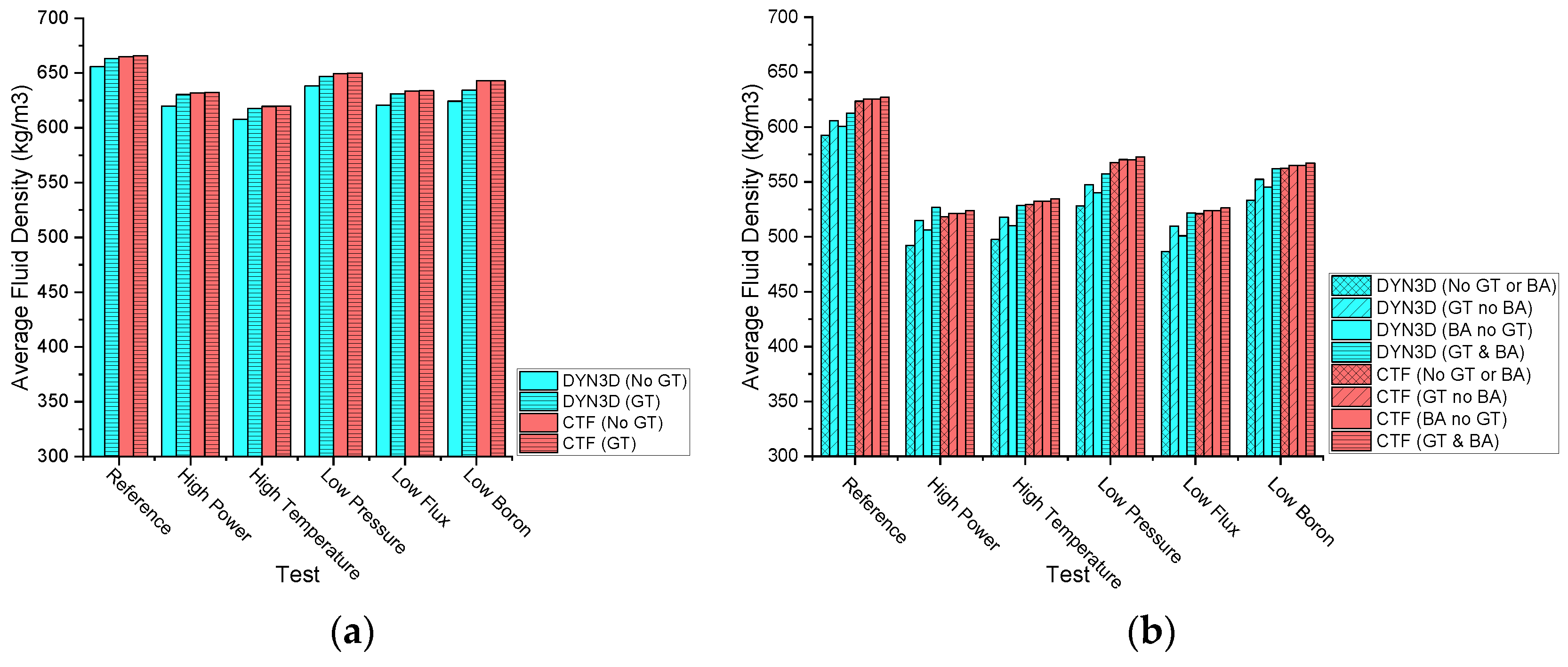
DYN3D to DYN3D and CTF coupling comparisons within the multi parameter variation exercise for the UOX-2 (CR) as well as the UOX-2 (BA16) 17 × 17 fuel assemblies are shown for the fluid density feedback, fluid temperature feedback, fuel temperature feedback, and the pressure drop feedback, while the mass flux feedback, void fraction feedback, and departure from nucleate boiling feedback are shown in the Appendix B. The location of the UOX-2 (CR) and the UOX-2 (BA16) fuel assemblies within the PWR reactor core can also be found in the Appendix B. The fluid density feedback value between fuel cells at the average axial node layer in both the UOX-2 (CR) and the UOX-2 (BA16) fuel assemblies is provided to show the similarities and differences between coupling values. All these values can be observed in Figure 4.
Both FLOCAL and CTF derive the fluid density by solving the fluid mass equation.
In both the DYN3D and the DYN3D and CTF couplings with or without burnable absorber pin and/or guide tube cells, the fluid density feedback value between fuel cells at the average axial node layer was observed to decrease in all the tests in the UOX-2 (BA16) fuel assembly when compared to in the UOX-2 (CR) fuel assembly. This fluid density feedback value decrease occurs due to lower power in the burnable absorber pin cells, which result in higher powers in the fuel pin cells, leading to an equivalent total power such as when there are equal powers in all the fuel pin cells, which results in lower fluid densities according to the fluid mass equation.
In both the DYN3D and the DYN3D and CTF couplings with or without burnable absorber pin and/or guide tube cells, the fluid density feedback value between fuel cells at the average axial node layer was observed to decrease with high power, high temperature, low pressure, low flux, and low boron when compared to the reference in both the UOX-2 (CR) and in the UOX-2 (BA16) fuel assemblies. This fluid density feedback value decrease occurs due to different reasons: In the high-power variation, this occurs due to the higher volumetric wall heat transfer term, which results in lower fluid densities according to the fluid mass equation. In the high temperature variation, this occurs due to higher inlet fluid enthalpy, which results in lower fluid densities according to the fluid mass equation. In the low-pressure variation, this occurs due to the lower pressure force term, which results in lower fluid densities according to the fluid mass equation. In the low mass flux variation, this occurs due to the lower inlet mass flow, which results in lower fluid densities according to the fluid mass equation. In the low boron variation, this occurs due to the lower boric acid concentration, which results in lower fluid densities according to the boron transport models.
In the DYN3D coupling without burnable absorber pin and/or guide tube cells compared to with burnable absorber pin and/or guide tube cells, the fluid density feedback value between all fuel cells at the average axial node layer was observed to decrease in all the tests in both the UOX-2 (CR) and in the UOX-2 (BA16) fuel assemblies. This fluid density feedback value decrease occurs particularly due to either the absence of power in the guide tube cells or lower power in the burnable absorber pin cells as well as in general due to the lack of mass transfer between fuel cells, leading to lower fluid densities according to the fluid mass equation.
In the DYN3D and CTF coupling without burnable absorber pin and/or guide tube cells compared to those with burnable absorber pin and/or guide tube cells, the fluid density feedback value between all fuel cells at the average axial node layer was observed to remain almost unchanged in all the tests in both the UOX-2 (CR) and in the UOX-2 (BA16) fuel assemblies. This fluid density feedback value near equivalence occurs, in general, due to the presence of mass transfer between fuel cells, leading to homogeneous fluid densities in both the guide tube cells and burnable absorber pin cells, which results, in general, in unchanged fluid densities, according to the fluid mass equation.
Between the DYN3D and the DYN3D and CTF couplings with or without burnable absorber pin and/or guide tube cells, the fluid density feedback values between fuel cells at the average axial node layer in both the UOX-2 (CR) and in the UOX-2 (BA16) fuel assemblies were observed to be different. These fluid density feedback value differences occurred due to different terms in the fluid mass equation including the evaporation as well as the crossflow and turbulent mixing models between fuel cells. According to the obtained fluid density feedback values between fuel cells at the average axial node layer in the UOX-2 (CR) fuel assembly, most variations can be regarded as compatible between both couplings while in the UOX-2 (BA16) fuel assembly, also most of the variations can be regarded as compatible between both couplings. Such variations can be regarded as compatible between couplings due to the similarity of the fluid density feedback values.
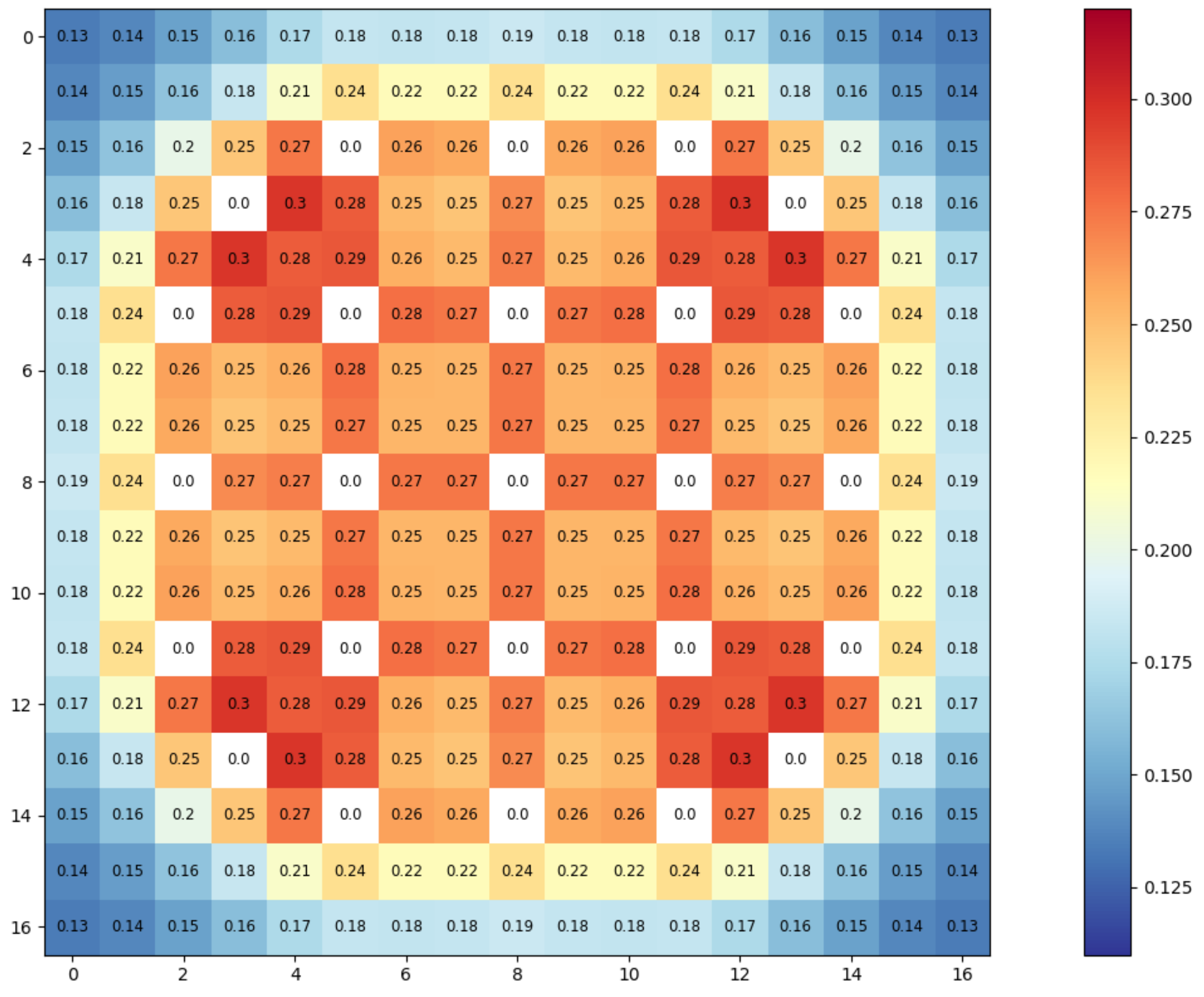
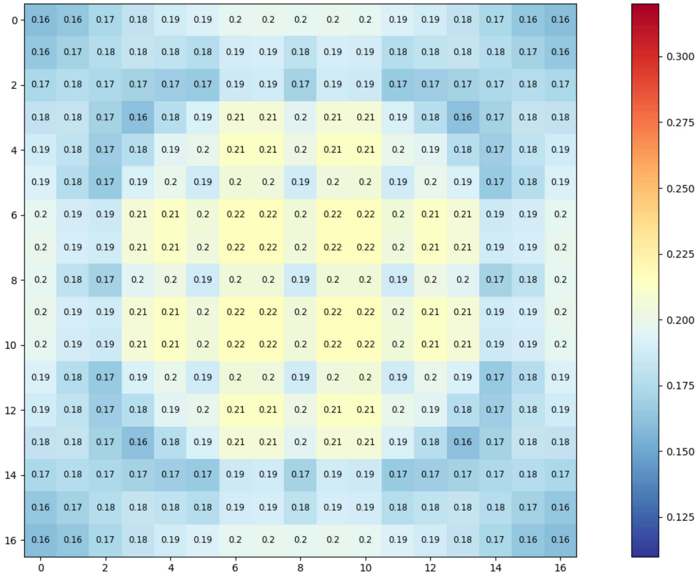
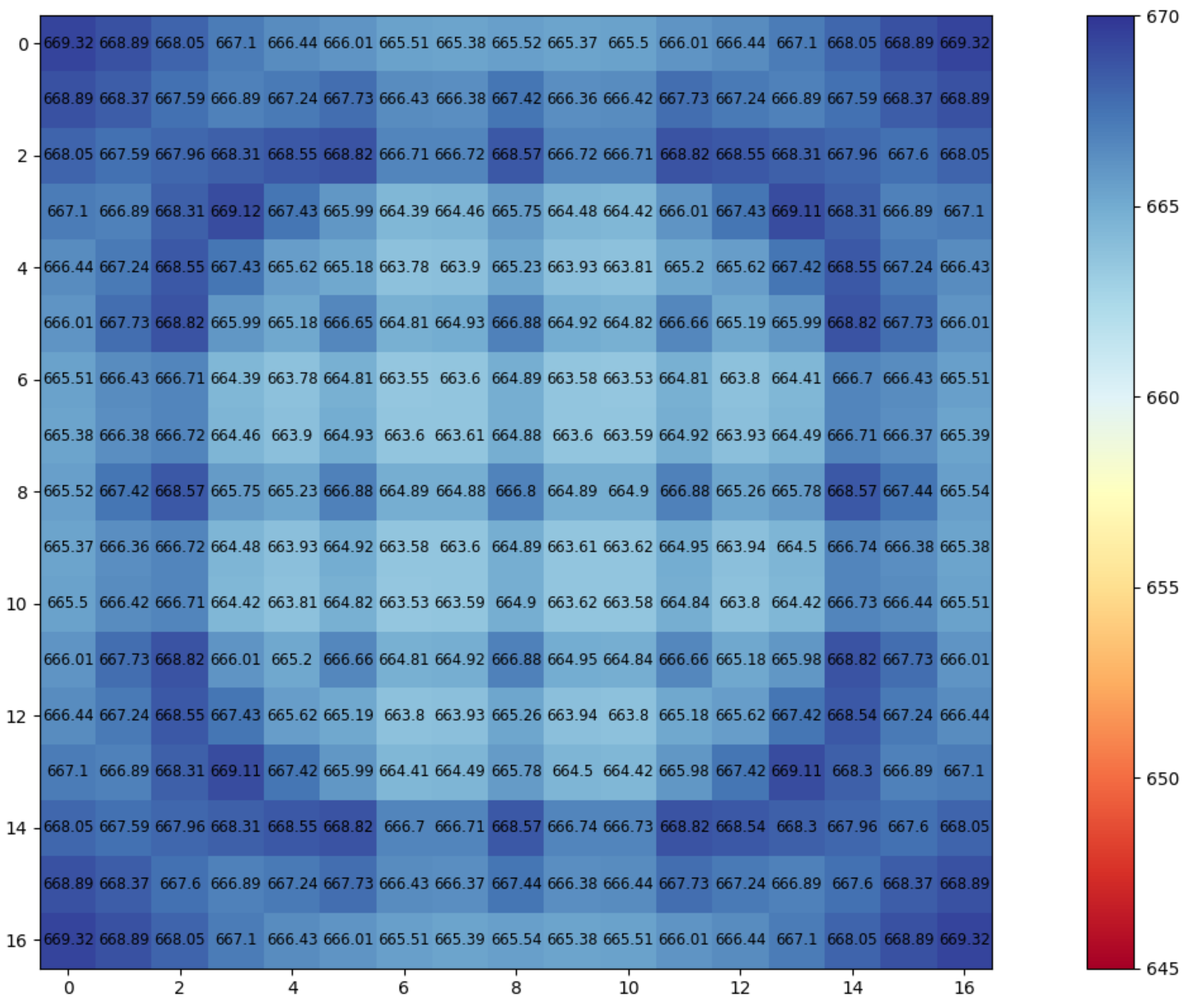
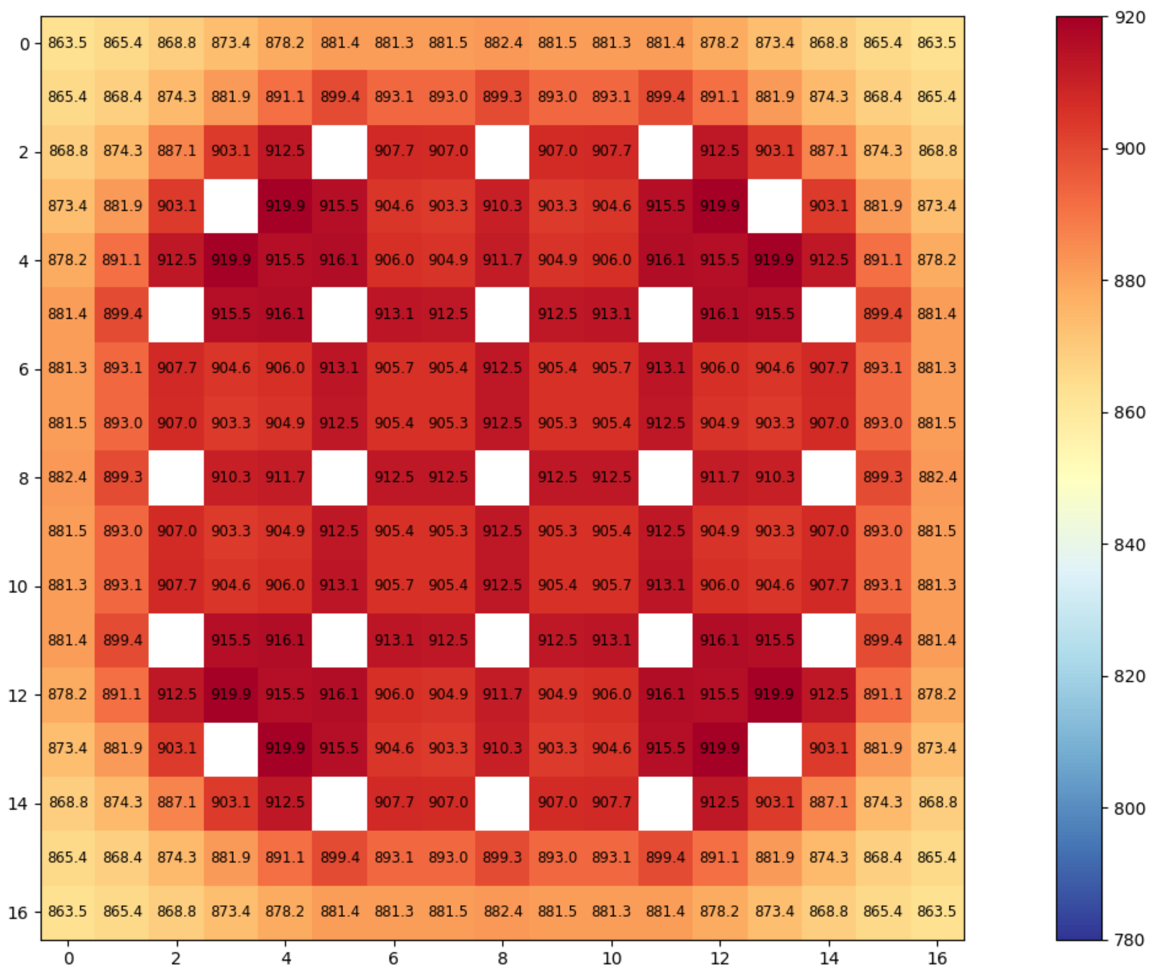
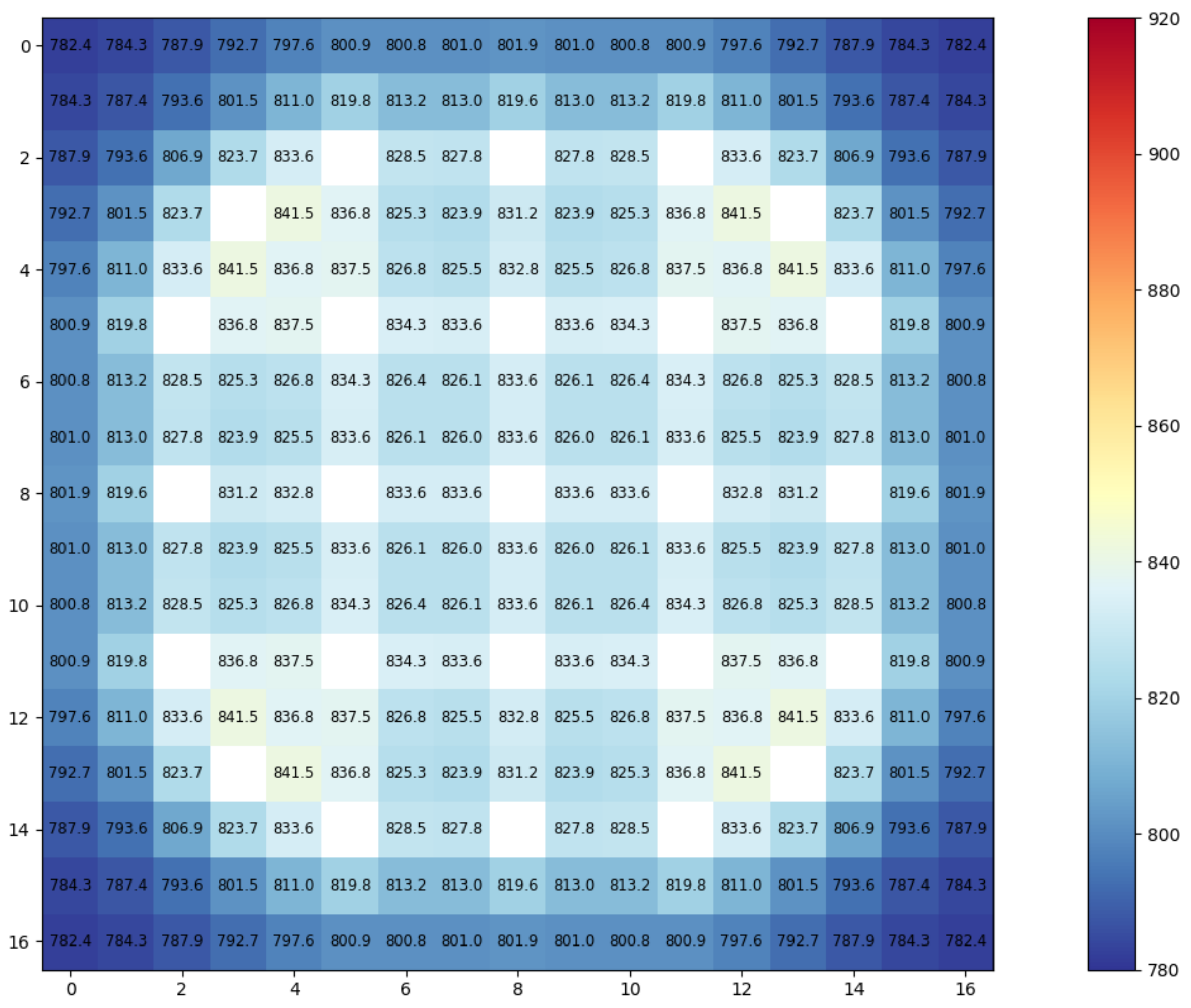
Transversal fluid density feedback distributions for all the fuel cells at the average axial node layer are provided for the UOX-2 (CR) fuel assembly compatible reference case to show the similarities and differences between both coupling distributions as observed in Figure 5 and Figure 6.
In both the DYN3D and the DYN3D and CTF couplings, the transversal fluid density feedback distribution for all fuel cells at the average axial node layer in the UOX-2 (CR) fuel assembly compatible reference case was observed to decrease more in the central than in the side or corner fuel cells. This transversal fluid density feedback distribution decrease occurred in both couplings due to the fuel cell neighbours, leading to higher heat fluxes in the central fuel cells, which resulted in lower fluid densities according to the fluid mass equation.
Between the DYN3D and the DYN3D and CTF couplings, the transversal fluid density feedback distribution for all the fuel cells at the average axial node layer in the UOX-2 (CR) fuel assembly compatible reference case were observed to be different. These transversal fluid density feedback distribution differences occurred due to different terms in the fluid mass equation including the evaporation as well as the crossflow and turbulent mixing models between fuel cells.
The fluid temperature feedback value between fuel cells at the average axial node layer in both the UOX-2 (CR) and the UOX-2 (BA16) fuel assemblies is provided to show the similarities and differences between the coupling values. All these values can be observed in Figure 7.
Both FLOCAL and CTF derive the fluid temperature from the fluid enthalpy, which is mainly obtained by solving the fluid energy equation.
In both the DYN3D and the DYN3D and CTF couplings with or without burnable absorber pin and/or guide tube cells, the fluid temperature feedback value between fuel cells at the average axial node layer was observed to increase in all the tests in the UOX-2 (BA16) fuel assembly when compared to in the UOX-2 (CR) fuel assembly. This fluid temperature feedback value increase occurred due to lower powers in the burnable absorber pin cells, which resulted in higher powers in the fuel pin cells, leading to an equivalent total power as when there are equal powers in all the fuel pin cells, which results in higher fluid enthalpies according to the fluid energy equation.
In both the DYN3D and the DYN3D and CTF couplings with or without burnable absorber pin and/or guide tube cells, the fluid temperature feedback value between fuel cells at the average axial node layer was observed to increase with high power, high temperature, low flux, and low boron when compared to the reference in both the UOX-2 (CR) and in the UOX-2 (BA16) fuel assemblies. This fluid temperature feedback value increase occurred due to different reasons: in the high-power variation, this occurred due to the higher volumetric wall heat transfer term, which resulted in higher fluid enthalpies according to the fluid energy equation. In the high temperature variation, this occurred due to higher inlet fluid enthalpy, which resulted in higher fluid enthalpies according to the fluid energy equation. In the low mass flux variation, this occurred due to the lower inlet mass flow, which resulted in higher fluid enthalpies according to the fluid energy equation. In the low boron variation, this occurred due to the lower boric acid concentration term, which resulted in higher fluid enthalpies according to the fluid energy equation. In both the DYN3D and the DYN3D and CTF couplings with or without burnable absorber pin and/or guide tube cells, the fluid temperature feedback value between all fuel cells at the average axial node layer was observed to remain constant with low pressure when compared to the reference in both the UOX-2 (CR) and in the UOX-2 (BA16) fuel assemblies.
In the DYN3D coupling without burnable absorber pin and/or guide tube cells compared to with burnable absorber pin and/or guide tube cells, the fluid temperature feedback value between fuel cells at the average axial node layer was observed to increase in all the tests in both the UOX-2 (CR) and in the UOX-2 (BA16) fuel assemblies. This fluid temperature feedback value increase occurred, in particular, due to either the absence of power in the guide tube cells or lower power in the burnable absorber pin cells as well as in general, due to the lack of energy transfer between fuel cells, leading to higher fluid enthalpies according to the fluid energy equation.
In the DYN3D and CTF coupling without burnable absorber pin and/or guide tube cells compared to with burnable absorber pin and/or guide tube cells, the fluid temperature feedback value between all fuel cells at the average axial node layer was observed to remain almost unchanged in all the tests in both the UOX-2 (CR) and in the UOX-2 (BA16) fuel assemblies. This fluid temperature feedback value near equivalence occurred, in general, due to the presence of energy transfer between fuel cells, leading to homogeneous fluid temperatures in both the guide tube cells and burnable absorber pin cells, which resulted, in general, in unchanged enthalpies according to the fluid energy equation.
Between the DYN3D and the DYN3D and CTF couplings with or without burnable absorber pin and/or guide tube cells, the fluid temperature feedback values between all fuel cells at the average axial node layer in both the UOX-2 (CR) and in the UOX-2 (BA16) fuel assemblies were observed to be different. These fluid temperature feedback value differences occurred due to different terms in the fluid energy equation including the nucleate boiling correlations as well as the crossflow and turbulent mixing models between fuel cells. According to the obtained fluid temperature feedback values between fuel cells at the average axial node layer in the UOX-2 (CR) fuel assembly, most variations can be regarded as compatible between both couplings while in the UOX-2 (BA16) fuel assembly, also most of the variations can be regarded as compatible between both couplings. Such variations can be regarded as compatible between couplings due to the similarity of the fluid temperature feedback values.
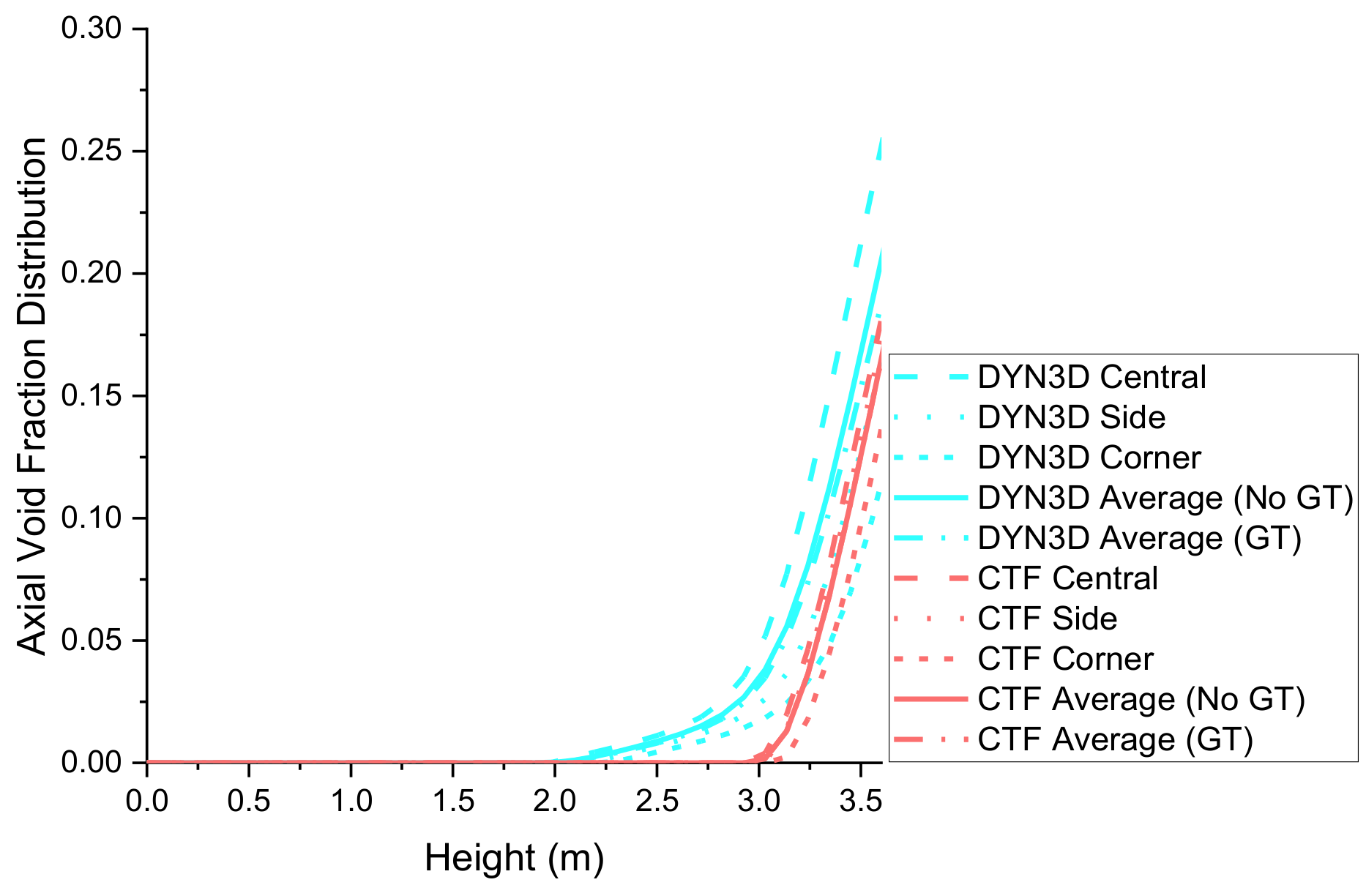
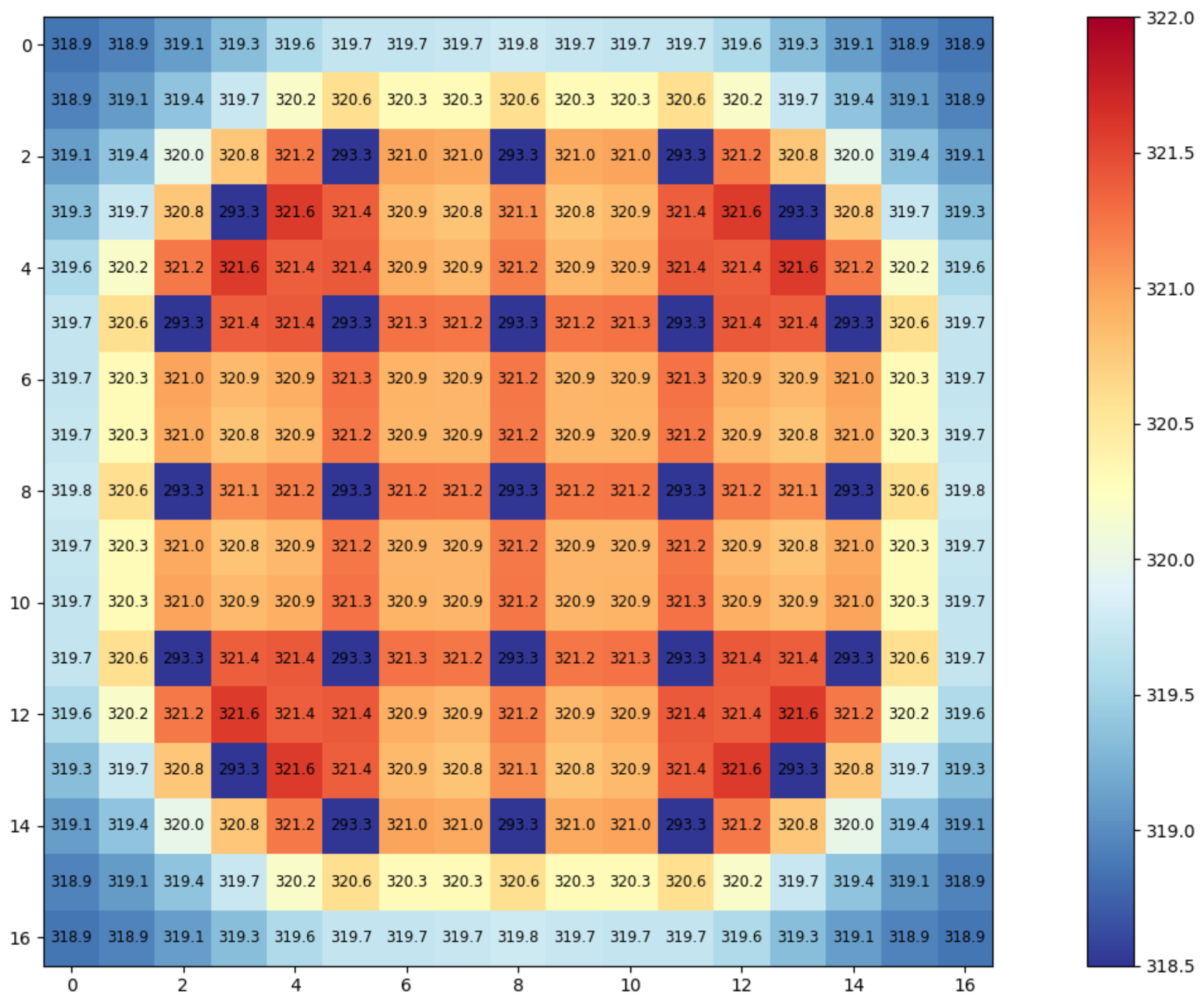
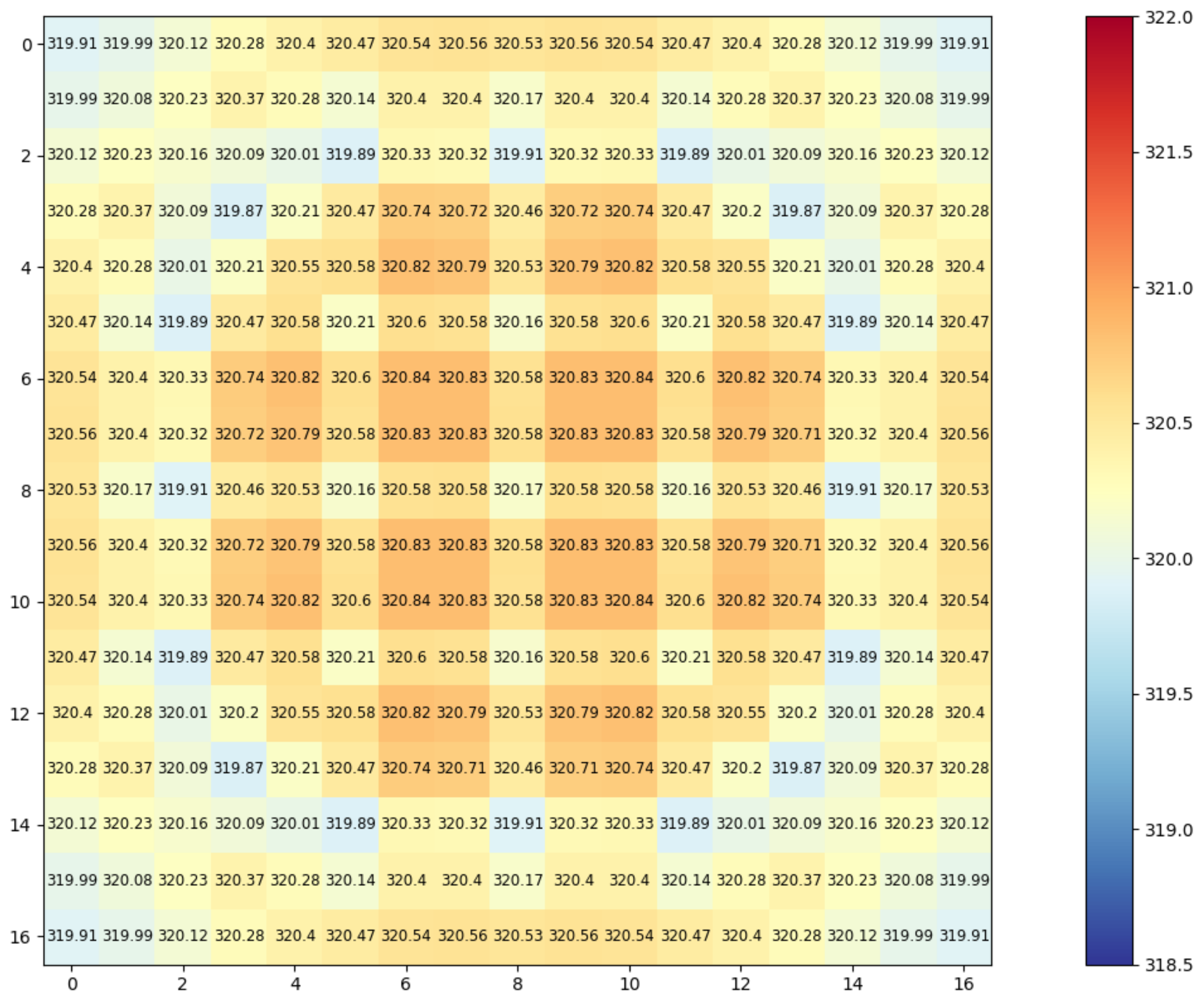
Axial fluid temperature feedback distributions for central, side, and corner fuel cells and average between fuel cells as well as transversal fluid temperature feedback distributions for all the fuel cells at the average axial node layer are provided for the UOX-2 (CR) fuel assembly compatible reference case to show the similarities and differences between both coupling distributions, as observed in Figure 8, Figure 9 and Figure 10.
In both the DYN3D and the DYN3D and CTF couplings, the axial fluid temperature feedback distribution for the central, corner, and side fuel cells as well as the transversal fluid temperature feedback distribution for all fuel cells at the average axial node layer in the UOX-2 (CR) fuel assembly compatible reference case was observed to increase more in the central than in the side or corner fuel cells. This axial and transversal fluid temperature feedback distribution increase occurred in both couplings due to the fuel cell neighbours, leading to higher heat fluxes in the central fuel cells, which resulted in lower fluid densities according to the fluid mass equation in the central fuel cells, which resulted in higher fluid enthalpies according to the fluid energy equation.
Between the DYN3D and the DYN3D and CTF couplings, the axial fluid temperature feedback distribution for the central, corner, and side fuel cells as well as the transversal fluid temperature feedback distribution for all the fuel cells at the average axial node layer for the UOX-2 (CR) fuel assembly compatible reference case were observed to be different. These axial and transversal fluid temperature feedback distribution differences occurred due to different terms in the fluid energy equation including the nucleate boiling correlations as well as the crossflow and turbulent mixing models between fuel cells.
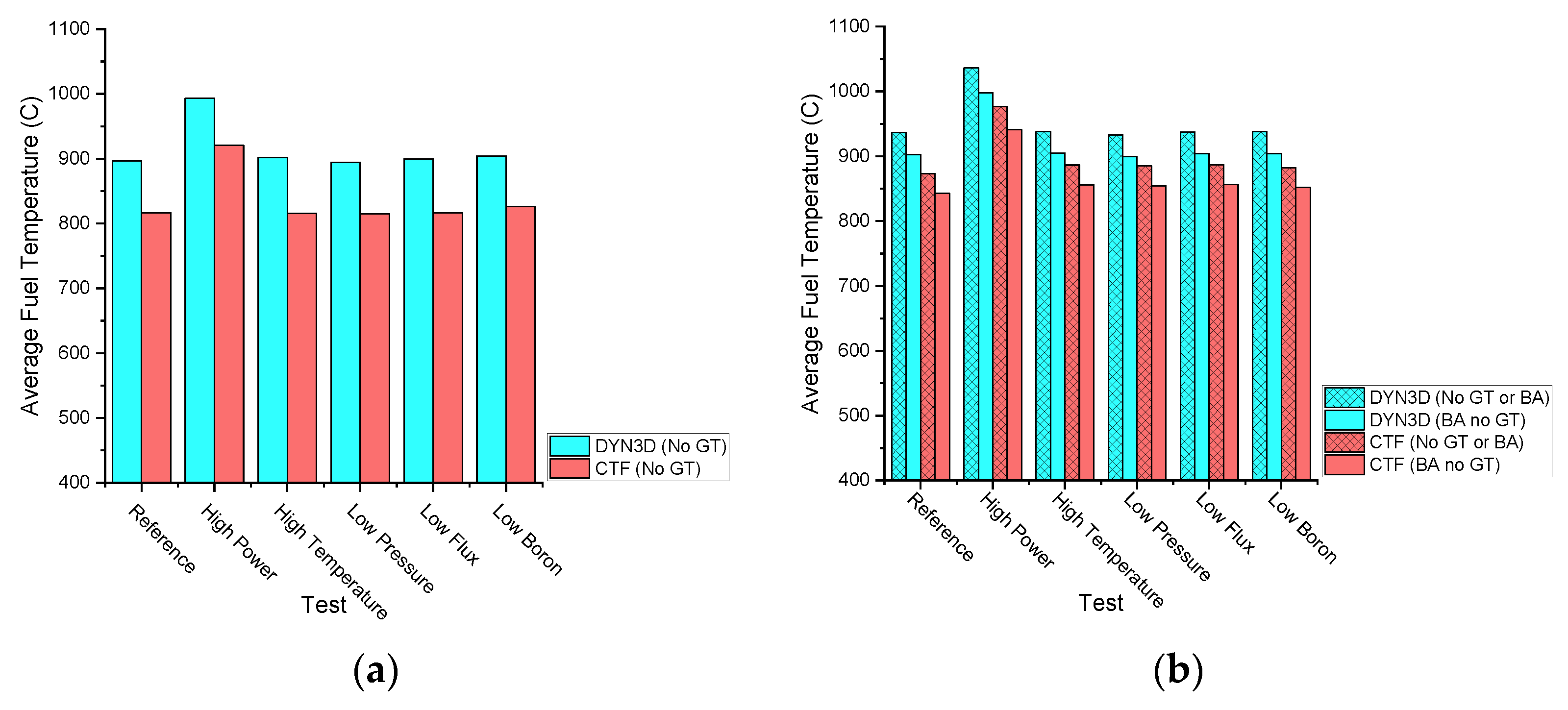
The fuel temperature feedback value between fuel pins at the average axial node layer in both the UOX-2 (CR) and the UOX-2 (BA16) fuel assemblies is provided to show the similarities and differences between coupling values. All these values can be observed in Figure 11.
Both FLOCAL and CTF derive the fuel temperature from the solid enthalpy, which is mainly obtained by solving the solid energy equation. In any case, the fuel temperature results from the volumetric heat density in the solid energy equation.
In both the DYN3D and the DYN3D and CTF couplings with or without burnable absorber pin cells and without guide tube cells, the fuel temperature feedback value between fuel pins at the average axial node layer was observed to increase in all the tests in the UOX-2 (BA16) fuel assembly when compared to the UOX-2 (CR) fuel assembly. This fuel temperature feedback value increase occurred due to lower powers in the burnable absorber pin cells, which resulted in higher powers in the fuel pin cells, leading to an equivalent total power as in the UOX-2 (CR) fuel assembly where there were equal powers in all the fuel pin cells, which resulted in higher solid enthalpies according to the solid energy equation.
In both the DYN3D and the DYN3D and CTF couplings with or without burnable absorber pin cells and without guide tube cells, the fuel temperature feedback value between fuel pins at the average axial node layer was observed to increase only with high power when compared to the reference in both the UOX-2 (CR) and in the UOX-2 (BA16) fuel assemblies. This fuel temperature feedback value increase occurred due to the higher volumetric heat density term, which resulted in higher solid enthalpies according to the solid energy equation. In both the DYN3D and the DYN3D and CTF couplings with or without burnable absorber pin cells and without guide tube cells, the fuel temperature feedback value between fuel pins at the average axial node layer was observed to remain constant with high temperature, low pressure, low flux, and low boron in both the UOX-2 (CR) and UOX-2 (BA16) fuel assemblies.
In both the DYN3D and the DYN3D and CTF couplings with or without burnable absorber pin cells and without guide tube cells, the fuel temperature feedback value between all fuel pins at the top axial node layer was observed in all the tests in both the UOX-2 (CR) and in the UOX-2 (BA16) fuel assemblies due to the absence of power in the guide tube cells.
In both the DYN3D and the DYN3D and CTF couplings with burnable absorber pin and without guide tube cells compared to without burnable absorber and guide tube cells, the fuel temperature feedback value between all fuel pins at the average axial node layer was observed to decrease in all the tests in the UOX-2 (BA16) fuel assembly. This fuel temperature feedback value decrease occurred due to lower power in the burnable absorber pin cells, leading to low temperatures in the burnable absorber pin cells, which resulted, in general, in lower solid enthalpies according to the solid energy equation.
Between the DYN3D and the DYN3D and CTF couplings with or without burnable absorber pin cells and without guide tube cells, the fuel temperature feedback value between fuel pins at the average axial node layer in both the UOX-2 (CR) and in the UOX-2 (BA16) fuel assemblies were observed to be different. These fuel temperature feedback value differences occurred due to different terms in the solid energy equation. According to the obtained fuel temperature feedback values between fuel pins at the average axial node layer in the UOX-2 (CR) fuel assembly, the variations can be regarded as less compatible between both couplings than in the UOX-2 (BA16) fuel assembly, where all variations can be regarded as compatible between both couplings. Such variations can be regarded as compatible between couplings due to the similarity of the fuel temperature feedback values.
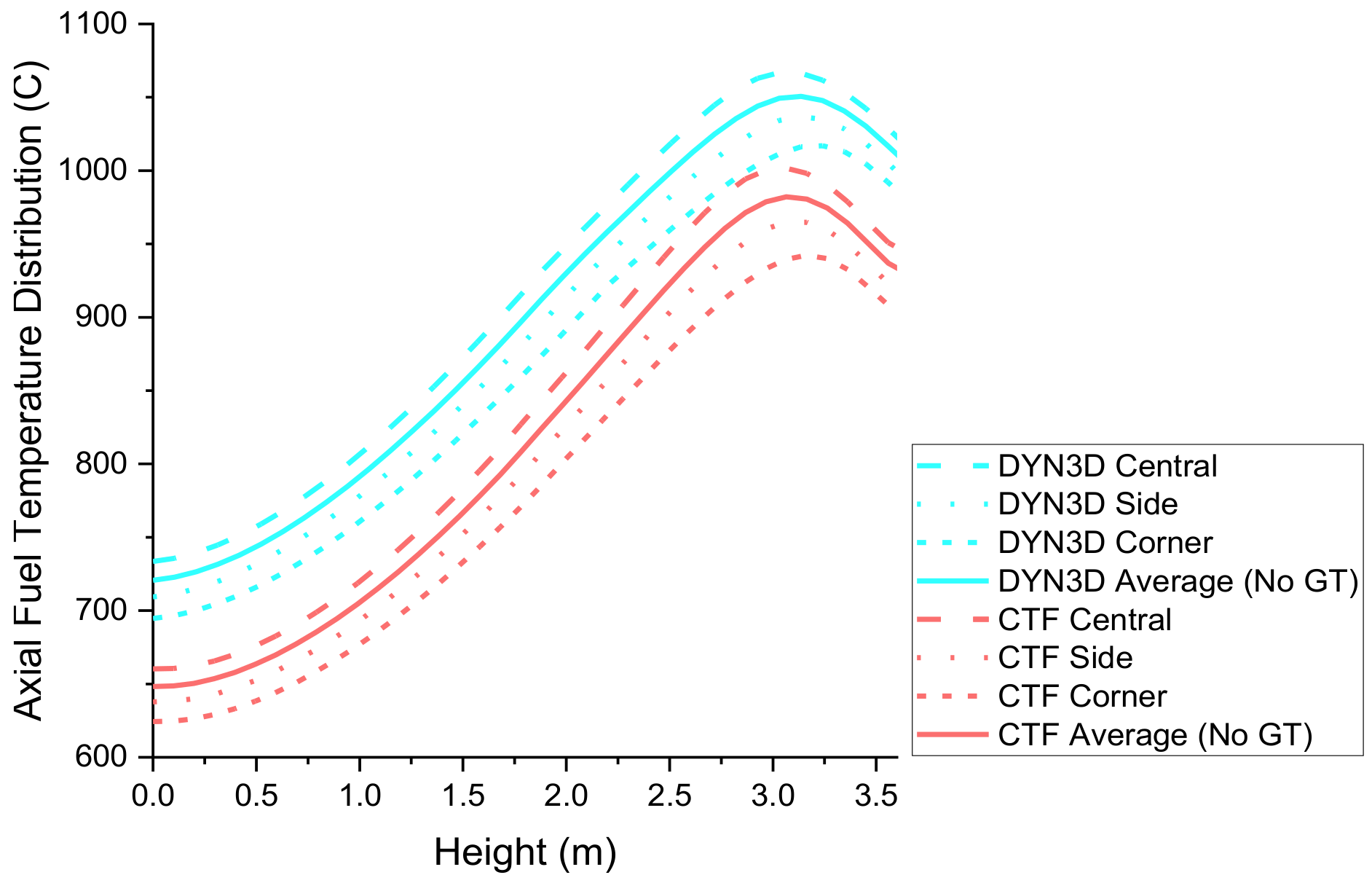
Axial fuel temperature feedback distributions for central, side, and corner fuel pins and average between fuel pins as well as transversal fuel temperature feedback distributions for all the fuel pins at the average axial node layer are provided for the UOX-2 (CR) fuel assembly compatible reference case to show the similarities and differences between both coupling distributions, as observed in Figure 12, Figure 13 and Figure 14.
In both the DYN3D and the DYN3D and CTF couplings, the axial fuel temperature feedback distribution for the central, corner, and side fuel pins as well as the transversal fuel temperature feedback distribution for all fuel pins at the average axial node layer in the UOX-2 (CR) fuel assembly compatible reference case were observed to increase more in the central fuel pins than in the side or corner fuel pins. This axial and transversal fuel temperature feedback distribution increase occurred in both couplings due to the fuel cell neighbours, leading to higher heat fluxes in the central fuel cells, which resulted in higher solid enthalpies according to the solid energy equation.
Between the DYN3D and the DYN3D and CTF couplings, the axial fuel temperature feedback distribution for the central, corner, and side fuel pins as well as the transversal fuel temperature feedback distribution for all the fuel pins at the average axial node layer in the UOX-2 (CR) fuel assembly compatible reference case were observed to be different. These axial and transversal fuel temperature feedback distribution differences occurred due to different terms in the solid energy equation.
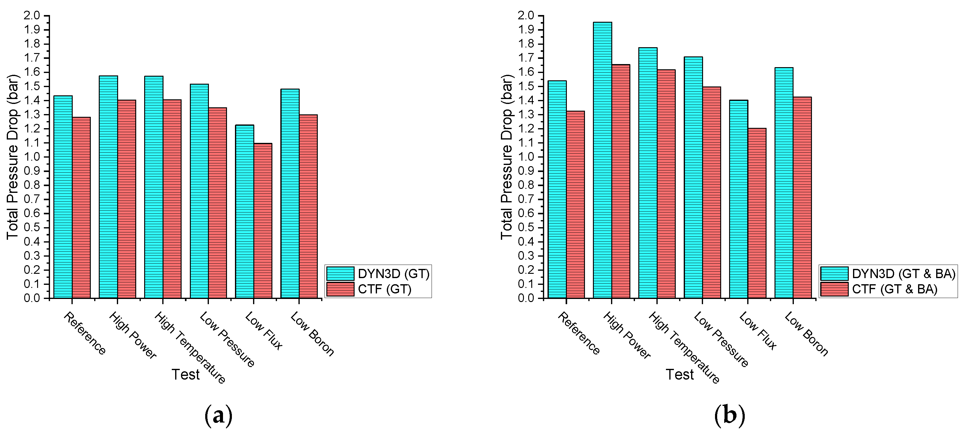
The pressure drop feedback value in both the UOX-2 (CR) and the UOX-2 (BA16) fuel assemblies is provided to show the similarities and differences between coupling values. All these values can be observed in Figure 15.
Both FLOCAL and CTF derive the pressure drop from the friction, form, gravity, and acceleration pressure losses, which are obtained through different pressure loss correlations. In any case, the pressure drop resulted from the pressure force term in the fluid momentum equation.
In both the DYN3D and the DYN3D and CTF couplings with burnable absorber pin and/or guide tube cells, was the pressure drop feedback value observed to increase in all the tests in the UOX-2 (BA16) fuel assembly when compared to in the UOX-2 (CR) fuel assembly. This pressure drop feedback value increase occurred due to lower powers in the burnable absorber pin cells, which resulted in higher powers in the fuel pin cells, leading to a higher pressure drop as when there were equal powers in all the fuel pin cells, which resulted in higher friction and acceleration pressure losses according to the pressure loss correlations.
In both the DYN3D and the DYN3D and CTF couplings with burnable absorber pin and/or guide tube cells, the pressure drop feedback value was observed to increase with high power, high temperature, and low pressure when compared to the reference in both the UOX-2 (CR) and in the UOX-2 (BA16) fuel assemblies. This pressure drop feedback value increase occurred due to different reasons: In the high-power variation, this occurred due to the higher volumetric wall heat transfer term, which resulted in higher friction and acceleration pressure losses according to the pressure loss correlations. In the high temperature variation, this occurred due to the higher inlet fluid enthalpy, which resulted in higher friction and acceleration pressure losses according to the pressure loss correlations. In the low-pressure variation, this occurred due to the lower pressure force term which results on higher friction and acceleration pressure losses according to the pressure loss correlations. In both the DYN3D and the DYN3D and CTF couplings with burnable absorber pin and/or guide tube cells, the pressure drop feedback value was observed to decrease with low flux when compared to the reference in both the UOX-2 (CR) and in the UOX-2 (BA16) fuel assemblies. This pressure drop feedback value decrease occurred due to the lower inlet mass flow, which resulted in lower friction and acceleration pressure losses according to the pressure loss correlations. In both the DYN3D and the DYN3D-CTF couplings with burnable absorber pin and/or guide tube cells, the pressure drop feedback value was observed to remain constant in the UOX-2 (CR) and UOX-2 (BA16) fuel assemblies with low boron when compared to the reference.
In both the DYN3D and the DYN3D and CTF couplings with burnable absorber pin and/or guide tube cells, the pressure drop feedback value was observed in all the tests in both the UOX-2 (CR) and in the UOX-2 (BA16) fuel assemblies as in the DYN3D coupling where only the pressure drop feedback value for the whole fuel assembly was available, while in the DYN3D and CTF coupling, full pressure distributions for each fuel cell were available.
Between the DYN3D and the DYN3D and CTF couplings with burnable absorber pin and/or guide tube cells, the pressure drop feedback values in the UOX-2 (CR) and in the UOX-2 (BA16) fuel assemblies were observed to be different. These pressure drop feedback value differences occurred due to different friction and form pressure loss correlations. According to the obtained pressure drop feedback values in the UOX-2 (CR) fuel assembly, all variations can be regarded as compatible between both couplings while in the UOX-2 (BA16) fuel assembly, also all the variations can be regarded as compatible between both couplings. Such varia-tions can be regarded as compatible between couplings due to the similarity of the pres-sure drop feedback values.

6. Conclusions

As has been observed, the current objective in the aim of coupling the nodal code DYN3D and the subchannel code CTF within the Multiscale and Multiphysics Software Development has been fulfilled as the coupling inner iterations within one outer iteration have been partially verified, providing improved coupled reactor physics at the fuel pin level, allowing to show through external coupling, the transfer of power distributions from DYN3D to CTF as well as the transfer of feedback distributions from CTF to DYN3D and as justify through thermal hydraulics when to use the DYN3D coupling and when to use the DYN3D and CTF coupling. The improved coupled reactor physics at the fuel pin level in the DYN3D and CTF coupling were only limited in terms of neutronics by neutron diffusion but complemented in terms of thermal hydraulics by the wide range of cross flow and turbulent mixing.
Considering the coupled reactor physics at the fuel pin level obtained using both the DYN3D and the DYN3D and CTF couplings through the replication of the KAIST benchmark, the DYN3D and CTF coupling provides improved feedback at the fuel pin level compared to the DYN3D coupling in the cases of the fluid density feedback, fluid temperature feedback, fuel temperature feedback, and pressure drop feedback. This may be in the case of the fluid density feedback due to different terms in the fluid mass equation including the evaporation as well as the crossflow and turbulent mixing models between fuel cells as the DYN3D and CTF coupling contains the latter models, as opposed to the DYN3D coupling. This may be the case of the fluid temperature feedback due to different terms in the fluid energy equation including the nucleate boiling correlation as well as the crossflow and turbulent mixing models between fuel cells as the DYN3D and CTF coupling contains the latter models, as opposed to the DYN3D coupling. This may be the case of the fuel temperature feedback due to different terms in the solid energy equation as the DYN3D and CTF coupling contains different models to the DYN3D coupling. This may be, in the case of the pressure drop feedback, due to different friction and form loss correlations as the DYN3D and CTF coupling contains different models to the DYN3D coupling.
In general, the DYN3D coupling provides similar feedback values as the DYN3D and CTF coupling, however, the DYN3D and CTF coupling provides improved feedback distributions over the DYN3D coupling as crossflow and other terms are modelled in the latter. Nevertheless, the DYN3D coupling requires lower simulation times than the DYN3D and CTF coupling to achieve results, as simulation times in the DYN3D coupling were around 1 to 2 min compared to 20 or more minutes in the DYN3D and CTF coupling, using in both cases a single core as conducted in serial simulations as opposed to multiple cores used in parallel simulations.

7. Future Work

Finally, the last objective in the aim of coupling the nodal code DYN3D and the subchannel code CTF within the Multiscale and Multiphysics software consists of the second part of the DYN3D and CTF coupling that will be performed to evaluate all outer iterations within the convergence criteria to provide fully verified improved coupled reactor physics at the fuel pin level. This evaluation will allow one to show through other couplings how the outer iterations within the convergence criteria takes place as well as justify through the neutronics when the DYN3D and CTF coupling, rather than just DYN3D, should be used to provide improved coupled reactor physics at the fuel pin level, or when LOTUS and any other fluid dynamics coupling should be used to provide full coupled reactor physics at the fuel pin level. The most pragmatic approach will always be taken to improve the economics and safety of nuclear reactors.

8. Nomenclature

The acronyms and symbols in the overall text have an associated meaning given below.
Acronyms:
AcronymFull Description
ADFAssembly Discontinuity Factor
AMRAdvanced Modular Reactor
ATHLETAnalysis of Thermal Hydraulics of Leaks and Transients
BA1616 Burnable Absorber Pins
BEISDepartment of Business, Energy and Industrial Strategy
CASLConsortium for Advanced Simulation of LWRS
CATHARECode for Analysis of Thermal Hydraulics during an Accident of Reactor and Safety Evaluation
CFDComputational Fluid Dynamics
CTF/COBRA-TFCoolant Boiling in Rod Arrays Two Fluid
CRControl Rods
DNB/DNBRDeparture from Nucleate Boiling
DRDDigital Reactor Design
DYN3D/FLOCALDynamical 3 Dimensional
EPREuropean Pressurised Reactor
FORTRANFormula Translator
HPCHinkley Point C
HZDRHelmholtz Zentrum Dresden Rossendorf
KAISTKorean Advanced Institute of Science and Technology
LOTUSLiverpool Transport Solver
LWRLight Water Reactor
NCSUNorth Carolina State University
NRCNuclear Regulation Commission
NURESIMNuclear Reactor Simulator
PNLPacific Northwest Laboratories
PSUPennsylvania State University
PWRPressurised Water Reactor
RELAP5Reactor Excursion and Leak Analysis Program
SCANAIRSystems of Codes for Analysing Reactivity Initiated Accidents
UKUnited Kingdom
UOLUniversity of Liverpool
Symbols:
SymbolFull Description
BA1616 Burnable Absorber Pins
c p c l a d Clad Specific Heat
c p f u e l Fuel Specific Heat
k c l a d Clad Thermal Conductivity
k f u e l Fuel Thermal Conductivity
FeIron
Gd2O3Digadolinium Trioxide
HeHelium
235U, 238UUranium Isotopes
UO2Uranium Dioxide
SnTin
ZrZirconium

Author Contributions

S.D., as the main author, wrote this article including the introduction, codes used in the verification, specifications used in the verification, models and scripts used in the verification, results and analysis, conclusions, and future work. D.L., as the next author, provided LOTUS as a result of being the developer and introduced the Multiscale and Multiphysics Software Development. U.R., as the next author, provided FLOCAL as a result of being the developer. A.D., as the next author, provided the fuel pin cross sections using SCALE-POLARIS. B.M. and A.L., as the next authors and academic supervisors, provided help from a theoretical perspective. P.B., as the next author and industrial supervisor, provided help from a theoretical perspective. V.R., as the last author and advisor, provided help from a practical perspective. All authors have read and agreed to the published version of the manuscript.

Funding

This research was funded by the EPSRC, EDF, and the UOL through the funding of the EPSRC grant “Innovative LWR Simulation Tool for the Nuclear Renaissance in the UK”, EPSRC grant number EP/R005850/1.

Institutional Review Board Statement

Not applicable.

Data Availability Statement

See the references.

Conflicts of Interest

The authors declare no conflict of interest. The funders had no role in the design of the study; in the collection, analyses, or interpretation of data; in the writing of the manuscript, or in the decision to publish the results.

Appendix A. Code Types

The spectral, lattice, neutron transport, nodal, system, subchannel, CFD, and fuel performance codes and risk assessment codes mentioned in the introduction are classified according to their type and developer in Table A1.
Table A1. Code descriptions.
CodeTypeDeveloper
ORIGENSpectralORNL
SCALESpectralORNL
APOLLO2LatticeAreva
INSILICONeutron TransportUT-Batelle
LOTUSNeutron TransportUOL
MPACTNeutron TransportORNL
SHIFTNeutron TransportORNL
COBAYA3NodalUPM
CRONOS2NodalCEA-Saclay
DYN3DNodalHZDR
ATHLETSystemGRS
CATHARESystemCEA-Grenoble
RELAP5SystemINL
CTFSubchannelPNL
FLICA4SubchannelCea-Saclay
SUBCHANFLOWSubchannelKIT
HYDRA-THCFDINL
NEPTUNECFDEDF
TRANS-ATCFDTRANS-AT
TRIO_UCFDIRSN
BISONFuel PerformanceINL
DRACCARFuel PerformanceIRSN
SCANAIRFuel PerformanceIRSN

Appendix B. KAIST Benchmark
The location of the UOX-2 (CR) and the UOX-2 (BA16) fuel assemblies within the LWR reactor core are presented in Figure A1.
Figure A1. UOX-2 (CR) and UOX-2 (BA16) locations within the KAIST 1A LWR reactor core.
Energies 14 05060 g0a1
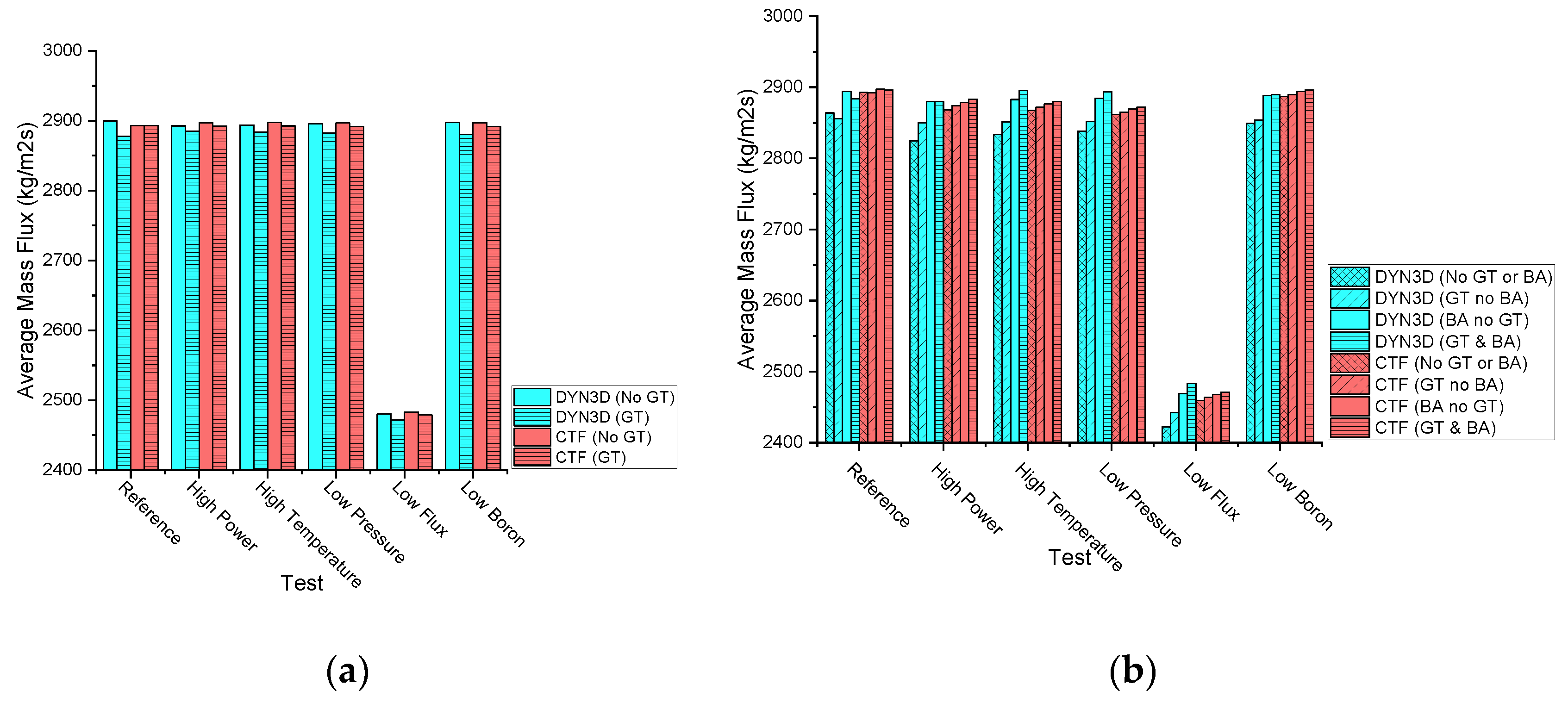
The mass flux feedback value between fuel cells at the average axial node layer in both the UOX-2 (CR) and the UOX-2 (BA16) fuel assemblies is provided to show the similarities and differences between coupling values. All these values can be observed in Figure A2.
Figure A2. (a) UOX-2 (CR) mass flux feedback values, (b) UOX-2 (BA16) mass flux feedback values.
Energies 14 05060 g0a2
Both FLOCAL and CTF derive the mass flux from the fluid density and fluid velocity, which are mainly obtained by solving the fluid mass and fluid momentum equations.
In both the DYN3D and the DYN3D and CTF couplings with or without burnable absorber pin and/or guide tube cells, the mass flux feedback value between fuel cells at the average axial node layer was observed to remain similar in all the tests in the UOX-2 (BA16) fuel assembly when compared to the UOX-2 (CR) fuel assembly. This mass flux feedback value near equivalence occurred due to mass conservation in the corresponding test.
In both the DYN3D and the DYN3D and CTF couplings with or without burnable absorber pin and/or guide tube cells, the mass flux feedback value between fuel cells at the average axial node layer was observed to decrease only with low flux when compared to the reference in both the UOX-2 (CR) and UOX-2 (BA16) fuel assemblies. This mass flux feedback value decrease occurred due to the lower inlet mass flow, which resulted in lower fluid densities as well as higher vapor and lower liquid velocities according to the fluid mass and fluid momentum equations. In both the DYN3D and the DYN3D and CTF couplings, the mass flux feedback value between fuel cells at the average axial node layer was observed to remain constant with high power, high temperature, low pressure, and low boron when compared to the reference in both the UOX-2 (CR) and in the UOX-2 (BA16) fuel assemblies.
In the DYN3D coupling with burnable absorber pin and/or guide tube cells compared to without burnable absorber pin and/or guide tube cells, the mass flux feedback value between all fuel cells at the average axial node layer was observed to decrease in all the tests in the UOX-2 (CR) fuel assembly and increase in all the tests in the UOX-2 (BA16) fuel assembly. This mass flux feedback value decrease and increase occurred, in particular, due to either the absence of power in the guide tube cells or lower power in the burnable absorber pin cells as well as in general due to the lack of mass and momentum transfer between fuel cells, leading to higher mass flux in either the guide tube or burnable absorber pin cells, which resulted, in general, in higher fluid densities, lower vapor, and higher liquid velocities according to the fluid mass and fluid momentum equations.
In the DYN3D and CTF coupling with burnable absorber pin and/or guide tube cells compared to without burnable absorber pin and/or guide tube cells, the mass flux feedback value between fuel cells at the average axial node layer was observed to decrease in all the tests in the UOX-2 (CR) fuel assembly and increase in all the tests in the UOX-2 (BA16) fuel assembly. This mass flux feedback value decrease and increase occurred, in general, due to the presence of mass and momentum transfer between fuel cells, leading to homogeneous mass flux in both the guide tube and burnable absorber pin cells, which resulted, in general, in almost unchanged fluid densities, vapor, and liquid velocities according to the fluid mass and fluid momentum equations.
Between the DYN3D and the DYN3D and CTF couplings with or without burnable absorber pin and/or guide tube cells, the mass flux feedback values between fuel cells at the average axial node layer in both the UOX-2 (CR) and in the UOX-2 (BA16) fuel assemblies were observed to be different. These mass flux feedback value differences occurred due to different terms in the fluid mass and fluid momentum equations including the evaporation, viscous stress as well as the crossflow and turbulent mixing models between fuel cells. According to the obtained mass flux feedback values between fuel cells at the average axial node layer in the UOX-2 (CR) fuel assembly, most variations can be regarded as compatible between both couplings while in the UOX-2 (BA16) fuel assembly, also most of the variations can be regarded as compatible between both couplings. Such variations can be regarded as compatible between couplings due to the similarity of the mass flux feedback values.
Axial mass flux feedback distributions for central, side, and corner fuel cells and average between fuel cells as well as transversal mass flux feedback distributions for all the fuel cells at the average axial node layer are provided for the UOX-2 (CR) fuel assembly compatible reference case to show the similarities and differences between both coupling distributions, as observed in Figure A3, Figure A4 and Figure A5.
Figure A3. Axial mass flux feedback distribution.
Energies 14 05060 g0a3
Figure A4. DYN3D coupling transversal mass flux feedback distribution.
Energies 14 05060 g0a4
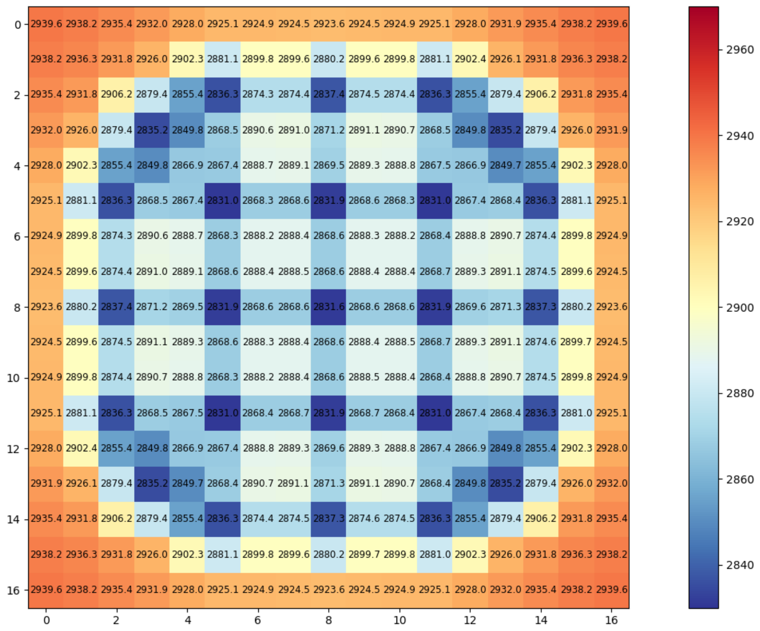
Figure A5. DYN3D and CTF coupling transversal mass flux feedback distribution.
Energies 14 05060 g0a5
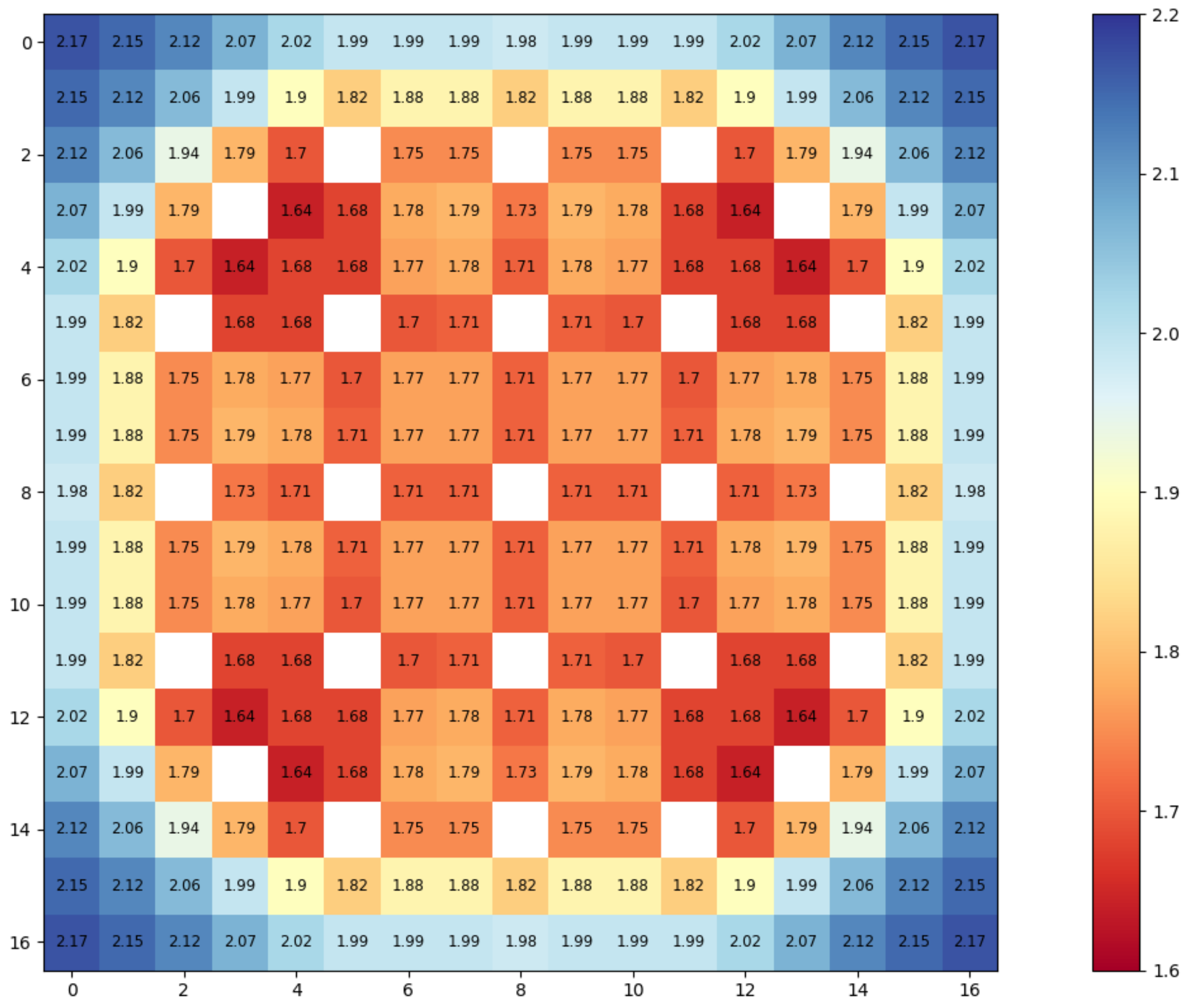
In both the DYN3D and the DYN3D and CTF couplings, the axial mass flux feedback distribution in the central, side, and corner fuel cells as well as the transversal mass flux feedback distribution for all fuel cells at the average axial node layer in the UOX-2 (CR) fuel assembly compatible reference case was observed to decrease more in the central than in the side or corner fuel cells. This axial and transversal mass flux feedback distribution decrease occurred in both couplings due to the fuel cell neighbours, leading to higher heat fluxes in the central fuel cells, which resulted in lower fluid densities, higher vapor, and lower liquid velocities according to the fluid mass and fluid momentum equations.
Between the DYN3D and the DYN3D and CTF couplings, the axial mass flux feedback distribution for the central, corner, and side fuel cells as well as the transversal mass flux feedback distribution for all the fuel cells at the average axial node layer in the UOX-2 (CR) fuel assembly compatible reference case were observed to be different. These axial and transversal mass flux feedback distribution differences occurred due to different terms in the fluid mass and fluid momentum equations including the evaporation, viscous stress as well as the crossflow and turbulent mixing models between fuel cells.
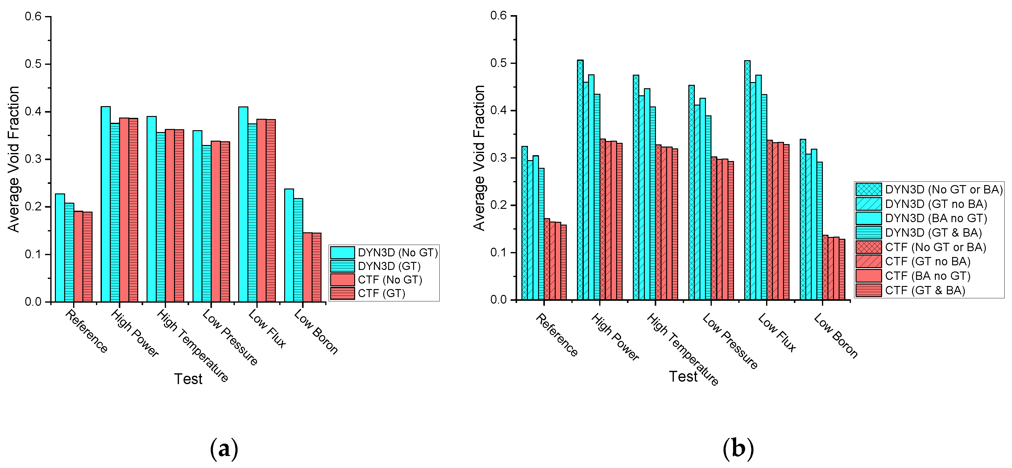
The void fraction feedback value between fuel cells at the top axial node layer in both the UOX-2 (CR) and the UOX-2 (BA16) fuel assemblies is provided to show the similarities and differences between coupling values. All these values can be observed in Figure A6.
Figure A6. (a) UOX-2 (CR) void fraction feedback values, (b) UOX-2 (BA16) void fraction feedback values.
Energies 14 05060 g0a6
Both FLOCAL and CTF derive the void fraction from the fluid density, fluid velocity, and fluid enthalpy, which are mainly obtained by solving the fluid mass, fluid momentum, and fluid energy equations.
Only in the DYN3D coupling with or without burnable absorber pin and/or guide tube cells, the void fraction feedback value between fuel cells at the top axial node layer was observed to increase in all the tests in the UOX-2 (BA16) fuel assembly when compared to in the UOX-2 (CR) fuel assembly. This void fraction feedback value increase occurred due to lower powers in the burnable absorber pin cells, which resulted in higher powers in the fuel pin cells, leading to an equivalent total power as when there were equal powers in all the fuel pin cells, which resulted in lower fluid densities, higher vapor, and lower liquid velocities as well as higher fluid enthalpies according to the fluid mass, fluid momentum, and fluid energy equations.
In both the DYN3D and the DYN3D and CTF couplings with or without burnable absorber pin and/or guide tube cells, the void fraction feedback value between fuel cells at the top axial node layer was observed to increase with high power, high temperature, low-pressure, and low flux when compared to the reference in both the UOX-2 (CR) and in the UOX-2 (BA16) fuel assemblies. This void fraction feedback value increase occurred due to different reasons: in the high-power variation, this occurred due to the higher volumetric wall heat transfer term, which resulted in lower fluid densities, higher vapor, and lower liquid velocities as well as higher fluid enthalpies according to the fluid energy equation. In the high temperature variation, this occurred due to higher inlet fluid enthalpy, which resulted in higher fluid enthalpies according to the fluid energy equation. In the low-pressure variation, this occurred due to the lower pressure force term, which resulted in lower fluid densities, higher vapor, and lower liquid velocities according to the fluid mass and fluid momentum equations. In the low mass flux variation, this occurred due to the lower inlet mass flow, which resulted in lower fluid densities, higher vapor, and lower liquid velocities as well as higher fluid enthalpies according to the fluid mass, fluid momentum, and fluid energy equations. Only in the DYN3D and CTF coupling with or without burnable absorber pin and/or guide tube cells was the void fraction feedback value between the fuel cells at the top axial node layer observed to decrease with low boron when compared to the reference in both the UOX-2 (CR) and in the UOX-2 (BA16) fuel assemblies. This void fraction feedback value decrease occurred due to the full boron transport model in the DYN3D and CTF coupling, which resulted in higher liquid velocities according to the boron tracking and precipitation equations when compared to the simplified boron transport model in the DYN3D coupling, which resulted in almost constant liquid velocities according to the simplified boron transport equation.
In the DYN3D coupling with burnable absorber pin and guide tube cells compared to without burnable absorber pin and/or guide tube cells, the void fraction feedback value between fuel cells at the top axial node layer was observed to decrease in all the tests in both the UOX-2 (CR) and in the UOX-2 (BA16) fuel assemblies. This void fraction feedback value decrease occurred, in particular, due to either the absence of power in the guide tube cells or lower power in the burnable absorber pin cells as well as in general due to the lack of mass, momentum, and energy transfer between fuel cells, leading to no vapor in the guide tube cells and low vapor in the burnable absorber pin cells, which resulted, in general, in higher fluid densities, lower vapor, and higher liquid velocities as well as higher fluid enthalpies according to the fluid mass, fluid momentum, and fluid energy equations.
In the DYN3D and CTF coupling with burnable absorber pin and guide tube cells compared to without burnable absorber pin and/or guide tube cells, the void fraction feedback value between fuel cells at the top axial node layer was observed to remain almost unchanged in all the tests in both the UOX-2 (CR) and in the UOX-2 (BA16) fuel assemblies. This void fraction feedback value near equivalence occurred, in general, due to the presence of mass, momentum, and energy transfer between fuel cells, leading to homogeneous vapor in both the guide tube cells and burnable absorber pin cells, which resulted, in general, in unchanged fluid densities, vapor, and liquid velocities as well as higher fluid enthalpies according to the fluid mass, fluid momentum, and fluid energy equations.
Between the DYN3D and the DYN3D and CTF couplings with or without burnable absorber pin and/or guide tube cells, the void fraction feedback values between all fuel cells at the top axial node layer in both the UOX-2 (CR) and in the UOX-2 (BA16) fuel assemblies were observed to be different. These void fraction feedback value differences occurred due to different terms in the fluid mass, fluid momentum, and fluid energy equations including the evaporation, viscous stress, nucleate boiling correlations as well as the crossflow and turbulent mixing models between fuel cells. According to the obtained void fraction feedback values between fuel cells at the top axial node layer in the UOX-2 (CR) fuel assembly, most variations can be regarded as compatible between both couplings, while in the UOX-2 (BA16) fuel assembly, almost none of the variations can be regarded as compatible between both couplings. Such variations can be regarded as compatible between couplings due to the similarity in the void fraction feedback values.
Axial void fraction feedback distributions for central, side, and corner fuel cells and average between fuel cells as well as transversal void fraction feedback distribution for all the fuel cells at the top axial node layer are provided for the UOX-2 (CR) fuel assembly compatible reference case to show the similarities and differences between both coupling distributions, as observed in Figure A7, Figure A8 and Figure A9.
Figure A7. Axial void fraction feedback distribution.
Energies 14 05060 g0a7
Figure A8. DYN3D coupling transversal void fraction feedback distribution.
Energies 14 05060 g0a8
Figure A9. DYN3D and CTF coupling transversal void fraction feedback distribution.
Energies 14 05060 g0a9
In both the DYN3D and the DYN3D and CTF couplings, the axial void fraction feedback distribution for the central, side, and corner fuel cells as well as the transversal void fraction feedback distribution for all fuel cells at the top axial node layer in the UOX-2 (CR) fuel assembly compatible reference case was observed to increase more in the central than in the side or corner fuel cells. This axial and transversal void fraction feedback distribution increase occurred in both couplings due to the fuel cell neighbours, leading to higher heat fluxes in the central fuel cells, which resulted, in general, in higher fluid densities, lower vapor, and higher liquid velocities as well as higher fluid enthalpies according to the fluid mass, fluid momentum, and fluid energy equations.
Between the DYN3D and the DYN3D and CTF couplings, the axial void fraction feedback distribution for the central, corner, and side fuel cells as well as the transversal void fraction feedback distribution for all the fuel cells at the top axial node layer for the UOX-2 (CR) fuel assembly compatible reference case was observed to be higher in the DYN3D coupling and lower in the DYN3D and CTF coupling. These axial and transversal void fraction feedback distribution differences occurred due to different terms in the fluid mass, fluid momentum, and fluid energy equations including the evaporation, viscous stress, nucleate boiling correlations as well as the crossflow and turbulent mixing models between fuel cells.
The relative departure from nucleate boiling feedback value between fuel pins at the top axial node layer in both the UOX-2 (CR) and the UOX-2 (BA16) fuel assemblies is provided to show the similarities and differences between coupling values. All these values can be observed in Figure A10.
Figure A10. (a) UOX-2 (CR) DNBR feedback values, (b) UOX-2 (BA16) DNBR feedback values.
Energies 14 05060 g0a10
Both FLOCAL and CTF derive the relative departure from nucleate boiling from the heat flux, which is mainly obtained by solving the solid energy equation as well as the critical heat flux, which is obtained using different empirical departure from nucleate boiling correlations.
In both the DYN3D and the DYN3D and CTF couplings without burnable absorber pin and/or guide tube cells, the relative departure from nucleate boiling feedback value between fuel pins at the top axial node layer was observed to decrease in some tests in the UOX-2 (BA16) fuel assembly when compared to the UOX-2 (CR) fuel assembly. This relative departure from nucleate boiling feedback value decrease occurred due to lower powers in the burnable absorber pin cells, which resulted in higher powers in the fuel pin cells, leading to an equivalent total power as when there were equal powers in all the fuel pin cells, which resulted in higher heat fluxes according to the solid energy equation.
In both the DYN3D and the DYN3D and CTF couplings without burnable absorber pin and/or guide tube cells, the relative departure from nucleate boiling feedback value between fuel pins at the top axial node layer was observed to decrease with high power, high temperature, low-pressure, and low flux when compared to the reference in both the UOX-2 (CR) and in the UOX-2 (BA16) fuel assemblies. This relative departure from the nucleate boiling feedback value decrease occurred due to different reasons: in the high-power variation, this occurred due to the higher volumetric wall heat transfer term, which resulted in higher heat fluxes according to the solid energy equation. In the high temperature variation, this occurred due to higher inlet fluid enthalpy, which resulted in higher critical heat fluxes according to the departure from nucleate boiling correlation. In the low-pressure variation, this occurred due to the lower pressure force term, which resulted in lower critical heat fluxes according to the critical heat flux correlation. In the low mass flux variation, this occurred due to the lower inlet mass flow, which resulted in lower critical heat fluxes according to the critical heat flux correlation. In both the DYN3D and the DYN3D and CTF couplings without burnable absorber pin and/or guide tube cells, the relative departure from nucleate boiling feedback value between fuel pins at the top axial node layer was observed to decrease with low boron when compared to the reference in the UOX-2 (BA16) fuel assembly. This relative departure from nucleate boiling feedback value increase in the low boron variation occurred due to the lower boric acid concentration term, which resulted in more heterogeneous heat fluxes according to the solid energy equation.
In both the DYN3D and the DYN3D and CTF couplings without burnable absorber pin and/or guide tube cells, the relative departure from nucleate boiling feedback value between all fuel pins at the top axial node layer was observed in all the tests in both the UOX-2 (CR) and in the UOX-2 (BA16) fuel assemblies due to either the absence of power in the guide tube cells or lower power in the burnable absorber pin cells, which resulted in higher relative departure from nucleate boiling feedback value in both the guide tube cells and burnable absorber pin cells.
Between the DYN3D and the DYN3D and CTF couplings without burnable absorber pin and guide tube cells, the relative departure from nucleate boiling feedback values between fuel pins at the top axial node layer in both the UOX-2 (CR) and in the UOX-2 (BA16) fuel assemblies were observed to be different. These relative departure from nucleate boiling feedback value differences occurred due to different critical heat flux correlations. According to the obtained relative departure from nucleate boiling feedback values between fuel pins at the top axial node layer in the UOX-2 (CR) fuel assembly, most variations can be regarded as compatible between both couplings while in the UOX-2 (BA16) fuel assembly, also most of the variations can be regarded as compatible between both couplings. Such variations can be regarded as compatible between couplings due to the similarity of the relative departure from nucleate boiling feedback values.
Axial relative departure from nucleate boiling feedback distributions for central, side, and corner fuel pins and average between fuel pins as well as transversal relative departure from nucleate boiling feedback distributions for all the fuel pins at the top axial node layer is provided for the UOX-2 (CR) fuel assembly compatible reference case to show the similarities and differences between both coupling distributions, as observed in Figure A11, Figure A12 and Figure A13.
Figure A11. Axial DNBR feedback distribution.
Energies 14 05060 g0a11
Figure A12. DYN3D coupling transversal DNBR feedback distribution.
Energies 14 05060 g0a12
Figure A13. DYN3D and CTF coupling transversal DNBR feedback distribution.
Energies 14 05060 g0a13
In both the DYN3D and the DYN3D and CTF couplings, the axial relative departure from nucleate boiling feedback distribution for the central, corner, and side fuel pins as well as the transversal relative departure from nucleate boiling feedback distribution for all fuel pins at the top axial node layer in the UOX-2 (CR) fuel assembly compatible reference case was observed to decrease more for the central fuel pins than for the side or corner fuel pins. This axial and transversal relative departure from nucleate boiling feedback distribution decrease occurred in both couplings due to the fuel cell neighbours, leading to higher heat fluxes in the central fuel cells according to the solid energy equation.
Between the DYN3D and the DYN3D and CTF couplings, the axial relative departure from nucleate boiling feedback distribution for the central, corner, and side fuel pins as well as the transversal departure from nucleate boiling distribution for all the fuel pins at the top axial node layer in the UOX-2 (CR) fuel assembly compatible reference case were observed to be different. These axial and transversal relative departures from nucleate boiling feedback distribution differences occurred due to different critical heat flux correlations.

References

  1. World Nuclear Association. World Nuclear Power Performance Report; World Nuclear Association: London, UK, 2020; pp. 1–68. [Google Scholar]
  2. Institution of Electric Engineers. Nuclear Reactor Types; Institution of Electric Engineers: London, UK, 2005; pp. 1–15. ISBN 085-296-581-8. [Google Scholar]
  3. Health and Safety Executive. Public Report on the Generic Design Assesment of New Nuclear Reactor Designs; Health and Safety Executive: Merseyside, UK, 2007; pp. 1–38. [Google Scholar]
  4. UK Government Funding for Nuclear Innovation. Available online: https://www.gov.uk/guidance/funding-for-nuclear-innovation (accessed on 13 August 2021).
  5. EDF Nuclear New Build Projects. Available online: https://www.edfenergy.com/energy/nuclear-new-build-projects (accessed on 13 August 2021).
  6. Rolls Royce UK Small Modular Reactor: Pioneering Intelligent Power. Available online: https://www.rolls-royce.com/products-and-services/nuclear/small-modular-reactors.aspx#/ (accessed on 13 August 2021).
  7. Kyrieleis, A. Digital Reactor Design. In Proceedings of the Nuclear Virtual Engineering Capability, Warrington, UK, 22 October 2019; pp. 1–30. [Google Scholar]
  8. Lee, J.C.; Arbor, A. Nuclear Reactor Physics and Engineering; Sons, J.W., Ed.; Department of Nuclear Engineering, The University of Michigan: Ann Arbor, MI, USA, 2020. [Google Scholar]
  9. Duderstadt, J.J.; Hamilton, L.J. Nuclear Reactor Analysis; John Wiley & Sons: Hoboken, NJ, USA; Department of Nuclear Engineering, The University of Michigan: Ann Arbor, MI, USA, 1975. [Google Scholar]
  10. Rubén, J.; Perelló, B. Development of a Coupled Neutronics/Thermal-Hydraulics/Fuel Thermo-Mechanics Multiphysics Tool for Best-Estimate PWR Core Simulations; Karlsruher Institut für Technologie: Karlsruhe, Germany, 2020; pp. 1–172. [Google Scholar]
  11. Hooper, R.; Spotz, W.; Lorber, A.; Schmidt, R. A Multi-Physics Coupling Approach for Integrated Nuclear Reactor Safety Calculations. In Proceedings of the ANS Annual Meeting, Anaheim, CA, USA, 8–12 June 2008; pp. 1–26. [Google Scholar]
  12. Gaston, D.R.; Permann, C.J.; Peterson, J.W.; Andrew, E.; Slaughter, D.A.; Wang, Y.; Short, M.P.; Perez, D.M.; Tonks, M.R.; Ortensi, J.; et al. Physics-based multiscale coupling for full core nuclear reactor simulation. Ann. Nucl. Energy 2015, 84, 45–54. [Google Scholar] [CrossRef] [Green Version]
  13. Romano, P.K.; Forget, B. The OpenMC Monte Carlo Particle Transport Code. Ann. Nucl. Energy 2013, 51, 274–281. [Google Scholar] [CrossRef] [Green Version]
  14. Litskevich, D. Development of an Advanced Neutron Transport Solver for Zooming in DYN3D; Rheinisch-Westfälischen Technischen Hochschule Aachen: Aachen, Germany, 2017; pp. 1–148. [Google Scholar]
  15. Detkina, A.; Peakman, A.; Litskevich, D.; Liang, J. Evaluation of BWR Burnup Calculations Using Deterministic Lattice Codes SCALE-6.2, WIMS-10A and CASMO5. Energies 2020, 13, 2573. [Google Scholar] [CrossRef]
  16. Omar, M.R.; Karim, J.A.; Yoon, T.L. The development of a multigroup Monte Carlo code for TRIGA reactors. Nucl. Eng. Des. 2019, 342, 99–114. [Google Scholar] [CrossRef]
  17. Rohde, U.; Grundmann, U.; Kliem, S. DYN3D—Advanced Reactor Simulations in 3D; Nuclear Energy Review 2007/II; Forschung Dresden Rossendorf: Dresden, Germany, 2007; pp. 1–4. [Google Scholar]
  18. EDF UK PANTHER: PWR AGR Neutronics Thermal Hydraulics Evaluation Route. Available online: https://www.answerssoftwareservice.com/panther/ (accessed on 13 August 2021).
  19. Bahadir, T.; Lindahl, S.-O. Studsvik’s next generation nodal code SIMULATE-5. In Proceedings of the Advances in Nuclear Fuel Management IV, Hilton Head Island, SC, USA, 12–15 April 2009; pp. 1–12. [Google Scholar]
  20. Davies, S.; Rohde, U.; Litskevich, D.; Merk, B.; Bryce, P.; Levers, A.; Detkina, A.; Atkinson, S.; Ravindra, V. CTF and FLOCAL Thermal Hydraulics Validations and Verifications within a Multiscale and Multiphysics Software Development. Energies 2021, 14, 1220. [Google Scholar] [CrossRef]
  21. Imke, U.; Sanchez, V.H. Validation of the Subchannel Code SUBCHANFLOW Using the NUPEC PWR Tests (PSBT). Hindawi 2012, 12. [Google Scholar] [CrossRef]
  22. Bajorek, S.M.; Bernard, M.; Gingrich, C.; Hoxie, C.L.; Ireland, A.; Kelly, J.; Mahaffy, J.; Murray, C.; Spore, J.; Staudenmeier, J.; et al. Development, Validation and Assessment of the Trace Thermal Hydraulics System Code. In Proceedings of the 16th International Topical Meeting on Nuclear Reactor Thermal Hydraulics, Chicago, IL, USA, 30 August–4 September 2015; Volume 14, pp. 1–14. [Google Scholar]
  23. Rossiter, G. Development of the ENIGMA fuel performance code for whole core analysis and dry storage assessments. Nucl. Eng. Technol. 2011, 43, 489–498. [Google Scholar] [CrossRef] [Green Version]
  24. Magni, A.; Nevo, A.D.; Luzzi, L.; Rozzia, D.; Adorni, M.; Schubert, A.P. Van Uffelen Chapter 8—The TRANSURANUS fuel performance code. Woodhead Publ. 2021, 8, 161–205. [Google Scholar] [CrossRef]
  25. Aybar, H.Ş.; Ortego, P. A review of nuclear fuel performance codes. Prog. Nucl. Energy 2005, 46. [Google Scholar] [CrossRef]
  26. Patelli, E. COSSAN: A Multidisciplinary Software Suite for Uncertainty Quantification and Risk Management; Springer: Cham, Switzerland, 2015. [Google Scholar] [CrossRef]
  27. Chauliac, C.; Aragones, J.; Bestion, D.; Weiss, F.-P. NURESIM—A European simulation platform for nuclear reactor safety: Multi-scale and multi-physics calculations, sensitivity and uncertainty analysis. Nucl. Eng. Des. 2011, 241, 3416–3426. [Google Scholar] [CrossRef]
  28. Euratom NURESIM Nuclear Reactor Safety Simulation Platform. Available online: https://cordis.europa.eu/project/id/323263 (accessed on 13 August 2021).
  29. Szilard, R.; Zhang, H.; Kothe, B.D.; Turinsky, P. CASL The Consortium for Advanced Simulation of Light Water Reactors; INL/CON-11-22917; INL: Idaho Falls, ID, USA, 2011. [Google Scholar]
  30. US Department of Energy CASL Consortium for Advanced Simulation of Light Water Reactors. Available online: https://casl.gov/ (accessed on 13 August 2021).
  31. Bergeaud, V.; Tajchman, M. Application of the SALOME Software Architecture to Nuclear Reactor Research. Soc. Comput. Simul. Int. 2007, 2, 383–387. [Google Scholar] [CrossRef]
  32. Sanchez, R.; Mondot, J.; Stankovski, Z.; Cossic, A. APOLLO II: A User-Oriented, Portable, Modular Code for Multigroup Transport Assembly Calculations. Nucl. Sci. Eng. 1988, 100, 352–362. [Google Scholar] [CrossRef]
  33. Jimenez, G.; Herrero, J.J.; Cuervo, D.; Garcia-Herranz, N.; AShnert, C. Boron dilution benchmark using COBAYA3/FLICA4 coupled codes within the NURISP European Project. In Proceedings of the 38 Annual Meeting of Spanish Nuclear Society, Caceres, Spain, 17–19 October 2012; Volume 44094049. [Google Scholar]
  34. Rohde, U.; Pivovarov, V.A.; Matveev, Y.A. Studies on boiling water reactor design with reduced moderation and analysis of reactivity accidents using the code DYN3D-MG. Kerntechnik 2012, 77, 240–248. [Google Scholar] [CrossRef]
  35. Höhne, T.; Bieder, U.; Prasser, H.-M.; Kliem, S. Validation of Trio_U for Transient Accident Scenarios—Numerical Simulations Of A Rocom Buoyancy Driven Test Case. In Proceedings of the 12th International Conference on Nuclear Engineering (ICONE-12), Washington, DC, USA, 25–29 April 2004. [Google Scholar]
  36. Karlsruhe Institute of Technology Subchannel Flow. Available online: https://www.inr.kit.edu/english/1008.php (accessed on 13 August 2021).
  37. Toumi, I.; Bergeron, A.; Gallo, D.; Royer, E.D. Caruge FLICA-4: A three-dimensional two-phase flow computer code with advanced numerical methods for nuclear applications. Nucl. Eng. Des. 2000, 200, 139–155. [Google Scholar] [CrossRef]
  38. Guelfi, A.; Bestion, D.; Boucker, M.; Pascal, B.; Philippe, F.; Marc, G. NEPTUNE: A New Software Platform for Advanced Nuclear Thermal Hydraulics. Nucl Sci. Eng. 2007, 156, 281–324. [Google Scholar] [CrossRef]
  39. Labois, M.; Narayanan, C.; Lakehal, D. PTS Prediction Using (the) CMFD Code TransAT: The COSI Test Case. In Computational Fluid Dynamics (CFD) for Nuclear Reactor Safety Applications—Workshop Proceedings; NEA: Paris, France, 2012; p. 1231. [Google Scholar]
  40. Geffraye, G.; Antoni, O.; Farvacque, M.; Kadri, D.; Lavialle, G.; Rameau, B.; Ruby, A. CATHARE 2 V2.5_2: A single version for various applications. Nucl. Eng. Des. 2011, 241, 4456–4463. [Google Scholar] [CrossRef]
  41. Di Marcello, V.; Escalante, J.J.; Espinoza, V.S. Validation of the thermal-hydraulic system code ATHLET based on selected pressure drop and void fraction BFBT tests. Nucl. Eng. Des. 2015, 288, 183–194. [Google Scholar] [CrossRef]
  42. Georges, R.; Francois, J.; Francois, B.; Francois, L.; Jean-Marc, R. DRACCAR, a new 3D-thermal mechanical computer code to simulate LOCA transient on nuclear power plants Status of the development and the validation. In Proceedings of the International Congress on Advances in Nuclear Power Plants, Tokyo, Japan, 10–14 May 2009; p. 2572. [Google Scholar]
  43. Moal, A.; Georgenthum, V.; Marchand, O. SCANAIR: A transient fuel performance code: Part One: General modelling description. Nucl. Eng. Des. 2014, 280, 150–171. [Google Scholar] [CrossRef]
  44. Kulesza, J.A.; Franceschini, F.; Evans, T.M.; Gehin, J.C. Overview of the Consortium for the Advanced Simulation of Light Water Reactors (CASL). EPJ Web Conf. 2016, 106, 8. [Google Scholar] [CrossRef] [Green Version]
  45. Nuclear Energy Agency. ORIGEN-22, Isotope Generation and Depletion Code Matrix Exponential Method. Available online: https://www.oecd-nea.org/tools/abstract/detail/ccc-0371 (accessed on 13 August 2021).
  46. Rearden, B.T.; Anderson, J.M. SCALE Code System 6.2.1. Int. At. Energy Agency 2016, 48, 1–2712. [Google Scholar]
  47. Kochunas, B.; Jabaay, D.; Downar, T.; Collins, B.S.; Stimpson, S.G.; Godfrey, A.T. Validation and Application of the 3D Neutron Transport Code MPACT within CASL VERA-CS. In Proceedings of the Sixteenth International Topical Meeting on Nuclear Reactor Thermal Hydraulics NURETH-16, Chicago, IL, USA, 30 August–4 September 2015; pp. 1–14. [Google Scholar]
  48. Hamilton, S.P.; Evans, M.E.; Davidson, G.G. Hot Zero Power Reactor Calculations Using the Insilico Code; Elsevier: Amsterdam, The Netherlands, 2016; Volume 314, pp. 700–711. [Google Scholar] [CrossRef] [Green Version]
  49. Pandya, T.M.; Johnson, S.R.; Evans, T.M.; Gregory, G. Implementation, Capabilities, and Benchmarking of Shift, a Massively Parallel Monte Carlo Radiation Transport Code; Elsevier: Amsterdam, The Netherlands, 2015; Volume 308, pp. 239–272. [Google Scholar] [CrossRef] [Green Version]
  50. Zhao, X.; Wysocki, A.J.; Shirvan, K.; Salko, R.K. Assessment of the Subchannel Code CTF for Single-and Two-Phase Flows. Nucl. Technol. 2019, 205, 338–351. [Google Scholar] [CrossRef]
  51. Christon, M.A.; International, C.S.; Bakosi, J.; Lowrie, R.B.; Pritchett-sheats, L. Hydra-TH: A Thermal-Hydraulics Code for Nuclear Reactor Applications. In Proceedings of the Fifteenth International Topical Meeting on Nuclear Reactor Thermal Hydraulics NURETH-15, Pisa, Italy, 12–17 May 2013; pp. 1–33. [Google Scholar]
  52. Hou, X.; Sun, Z.; Lei, W. Capability of RELAP5 code to simulate the thermal-hydraulic characteristics of open natural circulation. Ann. Nucl. Energy 2017, 109, 612–625. [Google Scholar] [CrossRef]
  53. Merk, B.; Bankhead, M.; Litskevich, D.; Gregg, R.; Peakman, A.; Shearer, C. On a Roadmap for Future Industrial Nuclear Reactor Core Simulation in the U.K. to Support the Nuclear Renaissance. Energies 2018, 11, 3509. [Google Scholar] [CrossRef] [Green Version]
  54. Labarile, A.; Olmo, N.; Miró, R.; Barrachina, T.; Verd, G. Comparison of SERPENT and SCALE methodology for LWRs transport calculations and additionally uncertainty analysis for cross-section perturbation with SAMPLER module. EPJ Nucl. Sci. Technol. 2016, 11, 1–14. [Google Scholar] [CrossRef] [Green Version]
  55. Litskevich, D.; Atkinson, S.; Davies, S. Verification of the current coupling collision probability method with orthogonal flux expansion for the assembly calculations. Prog. Nucl. Energy 2020, 130. [Google Scholar] [CrossRef]
  56. Jackson, P.; Turnbull, J. Enigma Fuel Performance Code. Nucl. Energy 1990, 21, 107–114. [Google Scholar]
  57. Torres, A.G.; Espinoza, V.S.; Imke, U.; Juan, R.M. Pin Level Neutronic—Thermalhydraulic Two-Way-Coupling Using DYN3D-SP3 And SUBCHANFLOW. In Proceedings of the International Conference on Mathematics and Computational Methods Applied to Nuclear Science and Engineering, Rio de Janeiro, Brazil, 8–12 May 2011; pp. 1–20. [Google Scholar]
  58. Atkinson, S.; Detkina, A.; Litskevich, D.; Merk, B. A Comparison of Advanced Boiling Water Reactor Simulations Between Serpent/CTF and Polaris/DYN3D: Steady State Operational Characteristics and Burnup Evolution. Energies 2021, 14, 40. [Google Scholar] [CrossRef]
  59. Zimin, V.G.; Nikonov, S.P. Coupling of the Neutron Diffusion Code SKETCH-N and the Thermal-Hydraulics System Code ATHLET for VVER-1000 Calculations. In Proceedings of the 28th Symposium of AER on VVER Reactor Physics and Reactor Safety, Olomouc, Czech Republic, 8–12 October 2018; pp. 1–20. [Google Scholar]
  60. Rohde, U.; Kliem, S.; Grundmann, U.; Baier, S.; Bilodid, Y.; Duerigen, S.; Fridman, E.; Gommlich, A.; Grahn, A.; Holt, L.; et al. The reactor dynamics code DYN3D—Models, validation and applications. Prog. Nucl. Energy 2016, 89, 140. [Google Scholar] [CrossRef]
  61. Grundmann, U.; Rohde, U. The Code DYN3D/M2 for the Calculation of Rectivity Initiated Transients in Light Water Reactors with Hexagonal Fuel Elements—Code Manual and Input Data Description; Helmholtz-Zentrum Dresden-Rossendorf: Dresden, Germany, 2012. [Google Scholar]
  62. Salko, R., Jr.; Avramova, M.; Wysocki, A.; Hu, J.; Toptan, A.; Porter, N.; Blyth, T.S. CTF 4.0 Theory Manual; ORNL: Oak Ridge, TN, USA, 2019. [Google Scholar] [CrossRef]
  63. Salko, R., Jr.; Avramova, M.; Wysocki, A.; Hu, J.; Toptan, A.; Porter, N.; Blyth, T.S. CTF 4.0 User Manual; ORNL: Oak Ridge, TN, USA, 2020. [Google Scholar] [CrossRef]
  64. Cho, N.Z. Benchmark Problem 1A: MOX Fuel-Loaded Small PWR Core (MOX Fuel with Zoning); KAIST/NurapT: Daejeon, Korea, 2000. [Google Scholar]
  65. Rohde, U.; Grundmann, U. DYNamical 3 Dimensional. Available online: https://www.hzdr.de/db/Cms?pOid=11771&pNid=542 (accessed on 13 August 2021).
  66. Avramova, M.; Toptan, A.; Porter, N. Coolant Boiling in Rod Arrays Two Fluid. Available online: https://www.ne.ncsu.edu/rdfmg/cobra-tf/ (accessed on 13 August 2021).
  67. Osmachkin, V.; Borisov, V. The hydraulic resistance of fuel rod bundles in a boiling water flow. IAEA 1970, 2, 24. [Google Scholar]
  68. McAdams, W. Heat Transmission; Pub, K., Ed.; McGraw-Hill: New York, NY, USA, 1985; ISBN 0898748763. [Google Scholar]
  69. Poljanin, L.; Ibragimov, M. Teploobmen v jadernikh reaktorakh. In Ehnergoizdat; USSR: Moscow, Russia, 1982; p. 296. [Google Scholar]
  70. Thorn, B.J.R.S.; Walkert, W.M.; Fallon, T.A.; Reising, G.F.S. Boiling in Subcooled Water During Flow up Heated Tubes or Annuli. Mater. Sci. 1965, 180, 226–246. [Google Scholar] [CrossRef]
  71. Bezrukov, Y.; Astakhov, V. Experimental investigation and static analysis of data on crisis of heat exchange in beams of rods for WWER reactors. Teploehnergetika 1976, 8, 80–82. [Google Scholar]
  72. Tong, L.S. Prediction of Departure from Nucleate Boiling for an Axially Non-Uniform Heat Flux Distribution. J. Nucl. Energy 1967, 21, 221–248. [Google Scholar] [CrossRef]
  73. Tong, L. Boiling Crisis and Critical Heat Flux; IAEA: Pittsburgh, PA, USA, 1972. [Google Scholar]
  74. Rogers, J.T.; Rosehart, R.G. Mixing by Turbulent Interchange in Fuel Bundles. In Correlations and Interfaces; ASME: New York, NY, USA, 1972. [Google Scholar]
Figure 1. (a) External coupling. (b) Internal coupling. (c) Parallel coupling.
Energies 14 05060 g001
Figure 2. (a) DYN3D UOX-2 (CR/BA16) 17 × 17 model, (b) CTF UOX-2 (CR/BA16) 17 × 17 model.
Energies 14 05060 g002
Figure 3. (a) DYN3D internal coupling, (b) DYN3D, and CTF external coupling.
Energies 14 05060 g003
Figure 4. (a) UOX-2 (CR) fluid density feedback values, (b) UOX-2 (BA16) fluid density feedback values.
Energies 14 05060 g004
Figure 5. DYN3D coupling transversal fluid density feedback distribution.
Energies 14 05060 g005
Figure 6. DYN3D and CTF coupling transversal fluid density feedback distribution.
Energies 14 05060 g006
Figure 7. (a) UOX-2 (CR) fluid temperature feedback values, (b) UOX-2 (BA16) fluid temperature feedback values.
Energies 14 05060 g007
Figure 8. Axial fluid temperature feedback distributions.
Energies 14 05060 g008
Figure 9. DYN3D coupling transversal fluid temperature feedback distribution.
Energies 14 05060 g009
Figure 10. DYN3D and CTF coupling transversal fluid temperature feedback distribution.
Energies 14 05060 g010
Figure 11. (a) UOX-2 (CR) fuel temperature feedback values, (b) UOX-2 (BA16) fuel temperature feedback values.
Energies 14 05060 g011
Figure 12. Axial fuel temperature feedback distributions.
Energies 14 05060 g012
Figure 13. DYN3D coupling transversal fuel temperature feedback distribution.
Energies 14 05060 g013
Figure 14. DYN3D and CTF coupling transversal fuel temperature feedback distribution.
Energies 14 05060 g014
Figure 15. (a) UOX-2 (CR) pressure drop feedback values, (b) UOX-2 (BA16) pressure drop feedback values.
Energies 14 05060 g015
Table 1. The 17 × 17 geometry from the KAIST benchmark.
Energies 14 05060 i001
TypeUOX-2 (CR) 17 × 17 AssemblyUOX-2 (BA16) 17 × 17 Assembly
Number of Fuel Pins264248
Number of Burnable Absorber Pins016
Number of Guide Tubes2525
Channel Width (m)0.21420.2142
Cell Width (m)0.01260.0126
Axial Length (Active) (m)3.6583.658
Energies 14 05060 i002
TypeFuel/Burnable Absorber Pin
Clad Diameter (m)0.0095
Clad Thickness (m)0.00057
Gap Thickness (m)0.000085
Fuel Pin Diameter (m)0.0082
Energies 14 05060 i003
TypeGuide Tube
Guide Tube Diameter (m)0.01224
Clad Thickness (m)0.000405
Table 2. The 17 × 17 materials from the KAIST benchmark.
Fuel Pin CompositionUO2 (3.3% 235U, 96.7% 238U)
Burnable Absorber Pin CompositionUO2 (0.711% 235U, 90.289% 238U) + Gd2O3 (9.0%)
Clad CompositionZircalloy (97.91% Zr, 1.59% Sn, 0.5% Fe)
Energy Groups (eV)Group 0 ≡ (0.62506, 2231300)
Group 1 ≡ (0.000014, 0.62506)
Fuel Density (kg/m3)10040
Fuel Specific Heat (J/kg K)
c p f u e l = 8.5013   10 8 e 535.285 T T 2 e 535.285 T 1 2   + 0.0243 T + 1.6587   10 12 T 2 e 18,968 T
Fuel Thermal Conductivity (W/m K)
k f u e l = max 2335 464 + T ,   1.1038 + 7.027   10 3   10 3   e 1.867   10 3   T
Clad Density (kg/m3)6400
Clad Specific Heat (J/kg K)
c p c l a d = 252.54 + 0.11474 T
Clad Thermal Conductivity (W/m K)
k c l a d = 7.51 + 2.09   10 2 T 1.45   10 5 T 2 + 7.67   10 9 T 3
Gap GasHe
Gap Heat Conductance (kJ/m2 K)5678
Table 3. The 17 × 17 spacer grids from the KAIST benchmark.
Pressure Loss Coefficient0.30
Spacer Grids Location (m)Uniform
Table 4. The 17 × 17 initial and boundary conditions.
CaseOutlet Pressure (Bar)Power (MW)Mass Flux (kg/m2 s)Inlet Temperature (C)Boric Acid Concentration (ppm)
Reference15525.9602889.33293.332250
High Power15530.2872889.33293.332250
High Temperature15525.9602889.33303.332250
Low Pressure14525.9602889.33293.332250
Low Flux15525.9602476.58293.332250
Low Boron15525.9602889.33293.331125
Publisher’s Note: MDPI stays neutral with regard to jurisdictional claims in published maps and institutional affiliations.