
Parameter Matching of Energy Regeneration System for Parallel Hydraulic Hybrid Loader


Abstract
:1. Introduction
2. Structure and Models
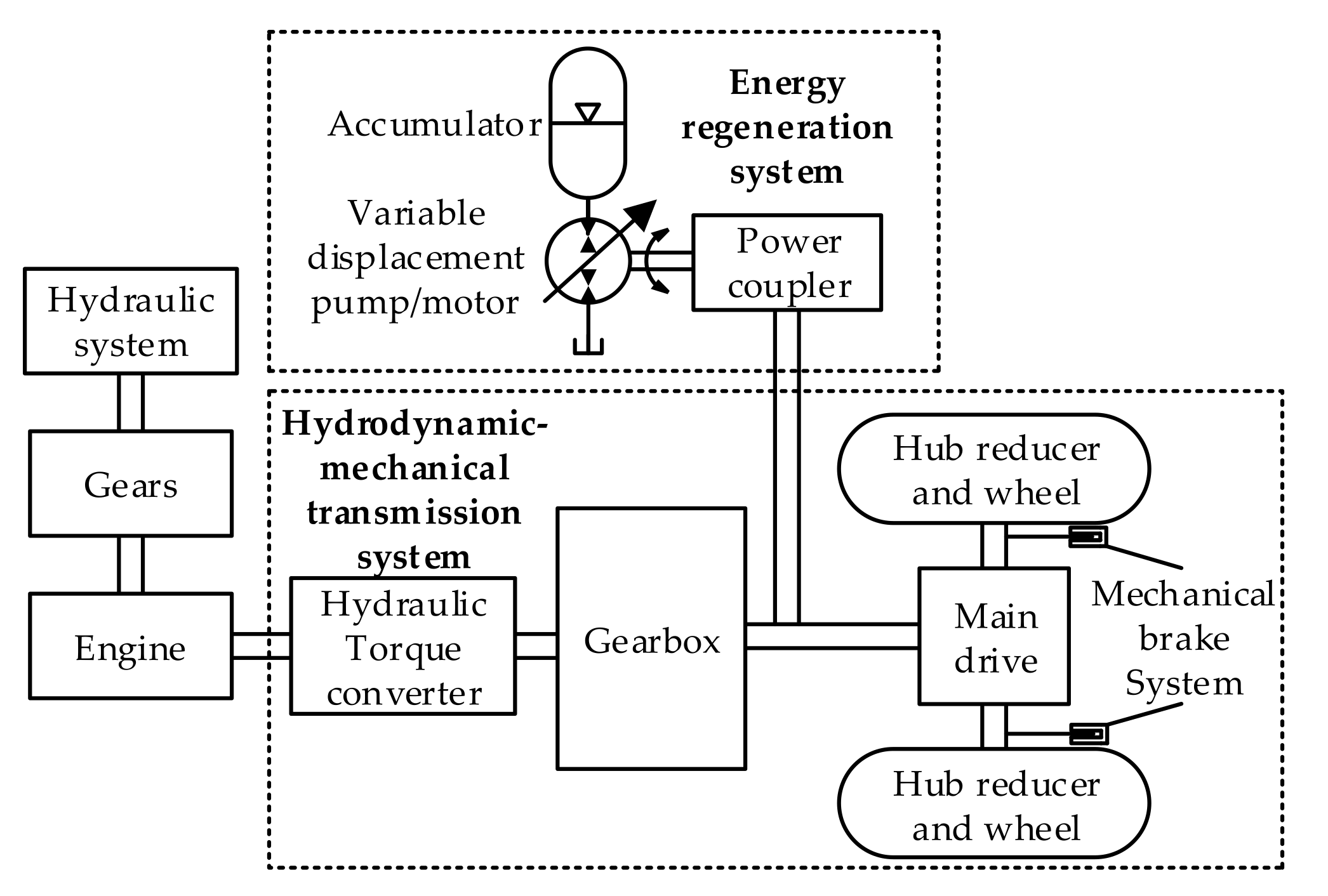
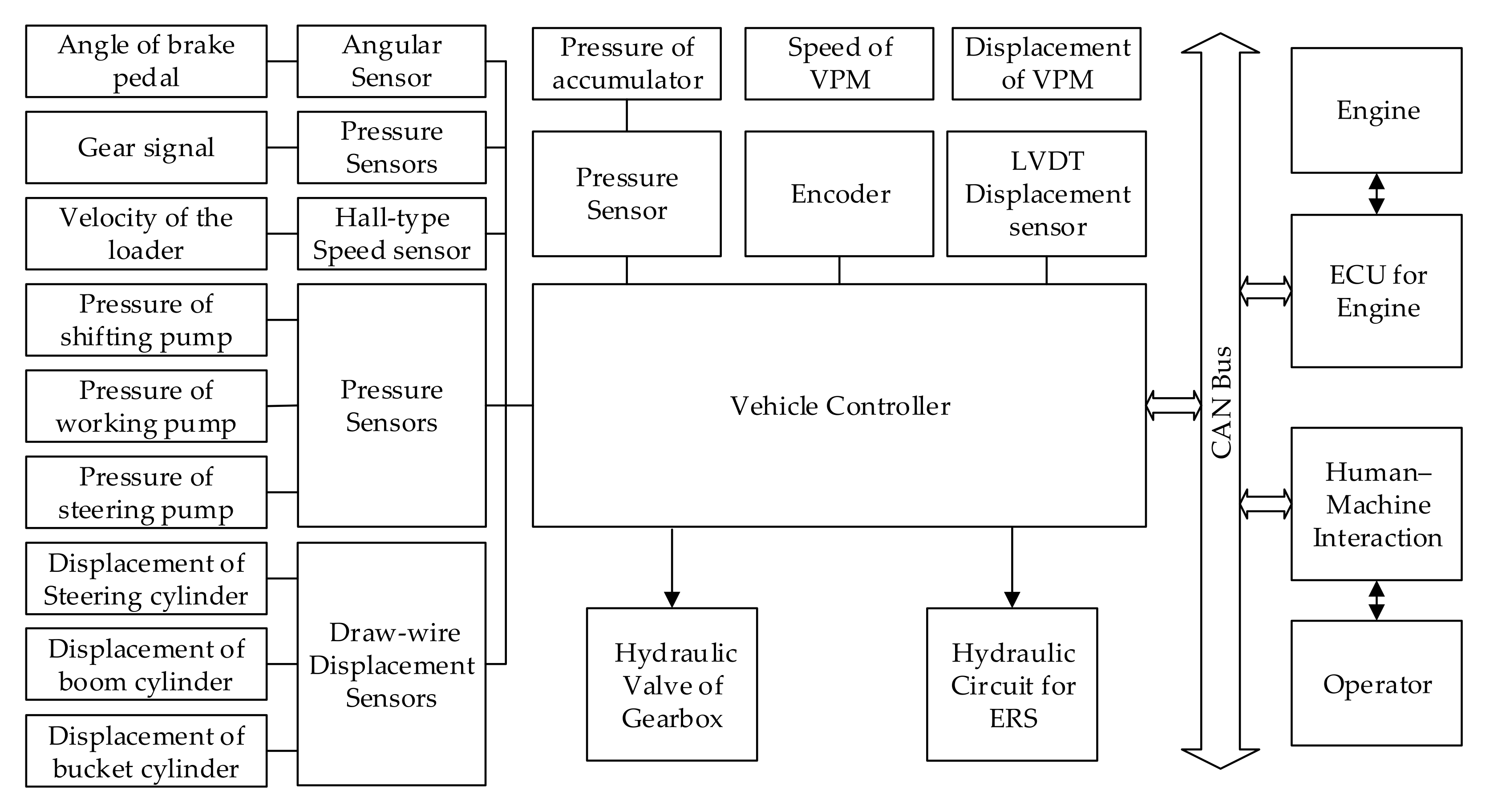
2.1. Structure
2.2. Engine Modeling
2.3. HMTS Modeling
2.4. ERS Modeling
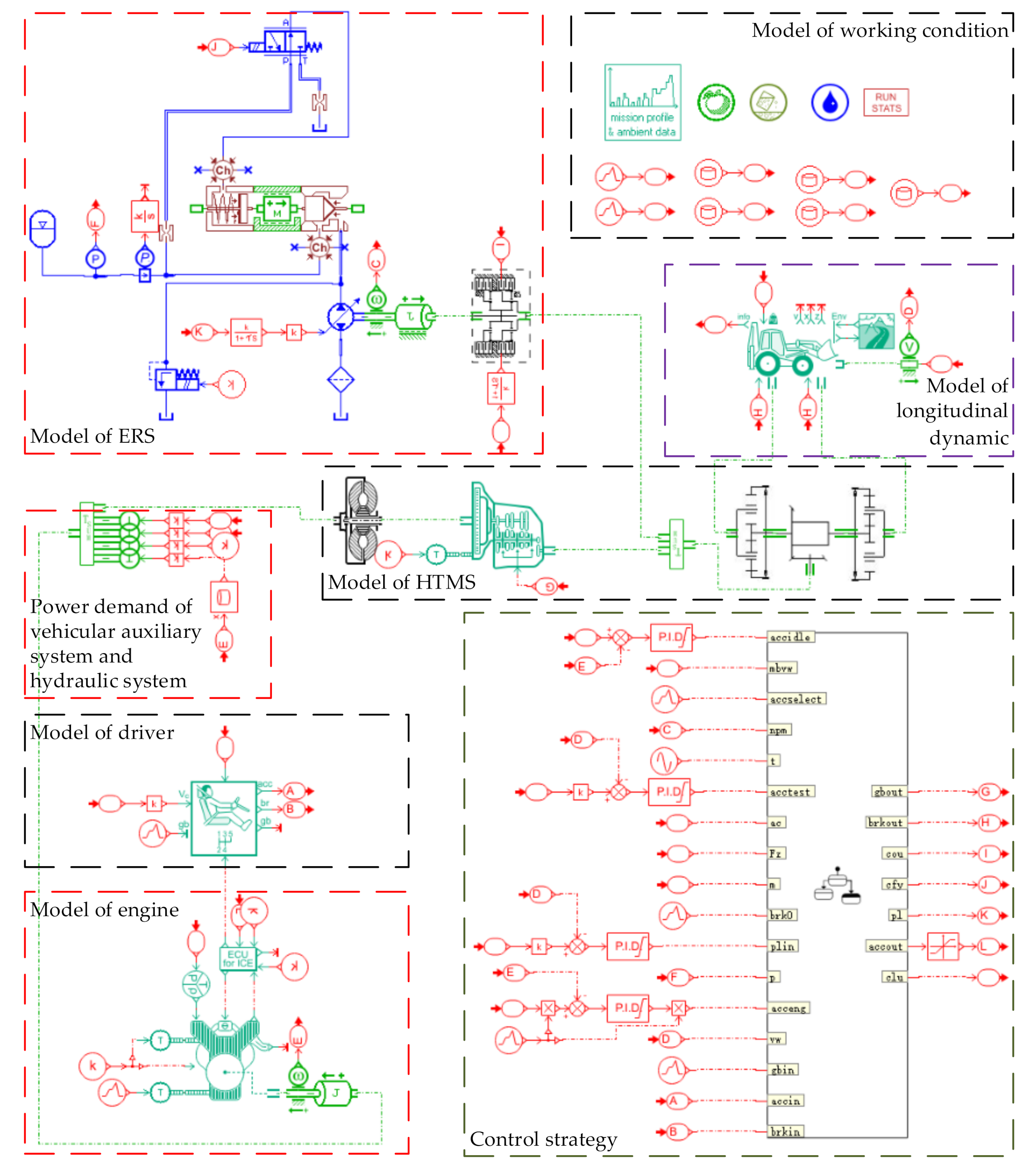
2.5. Final Model of the PHHL
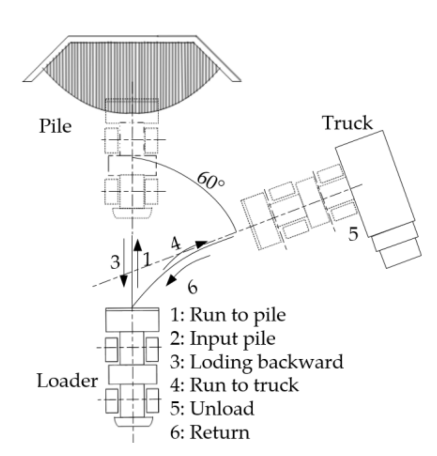
3. Duty Cycle
3.1. Energy Saving Potential
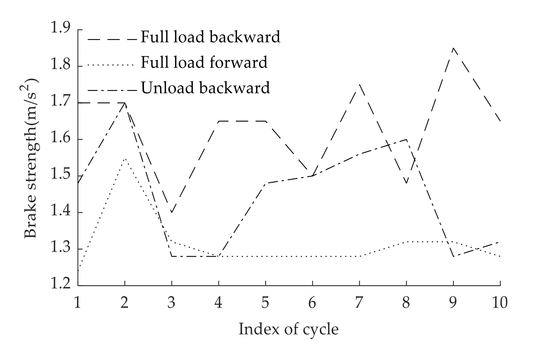
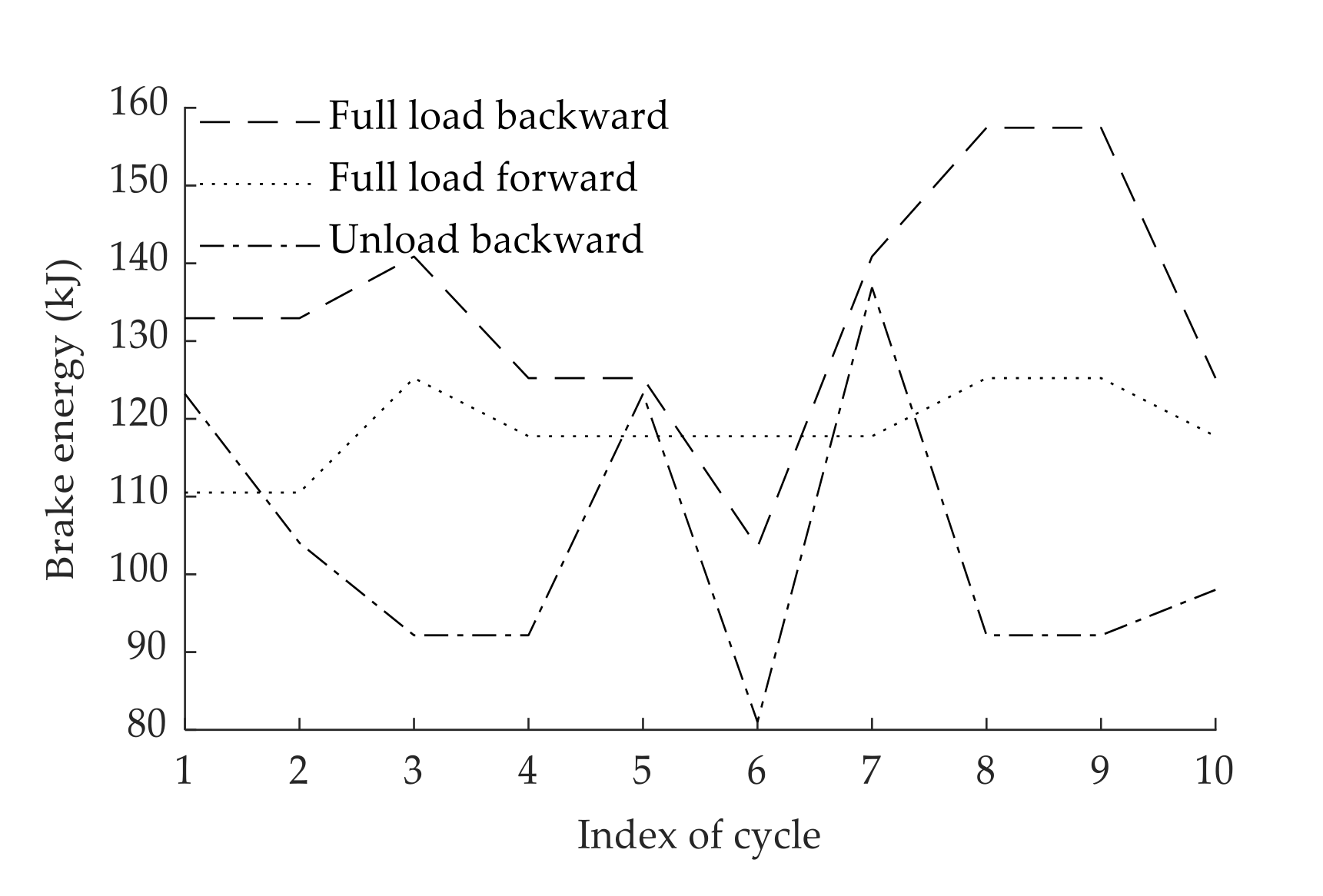
3.2. Analysis of Brake Strength
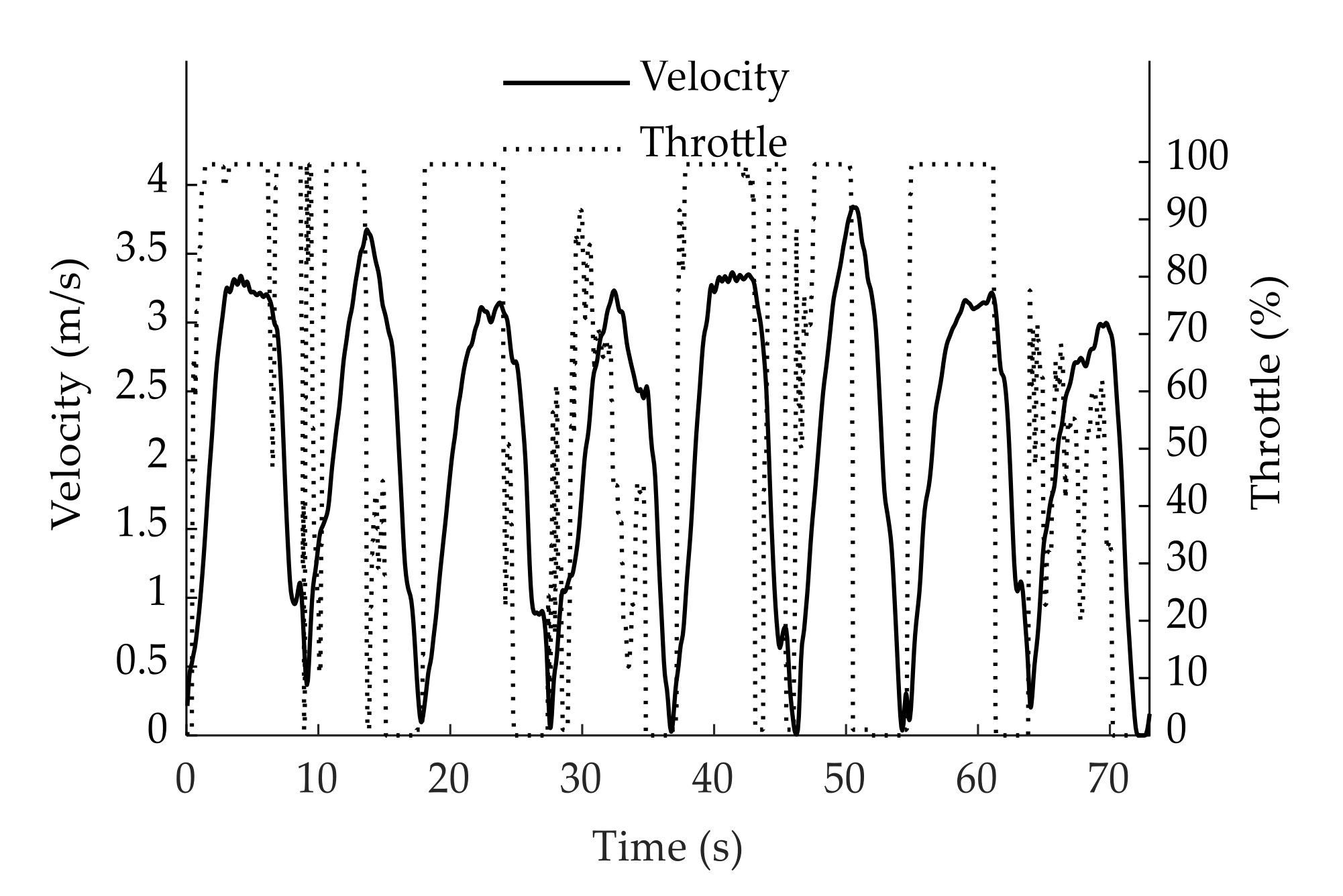
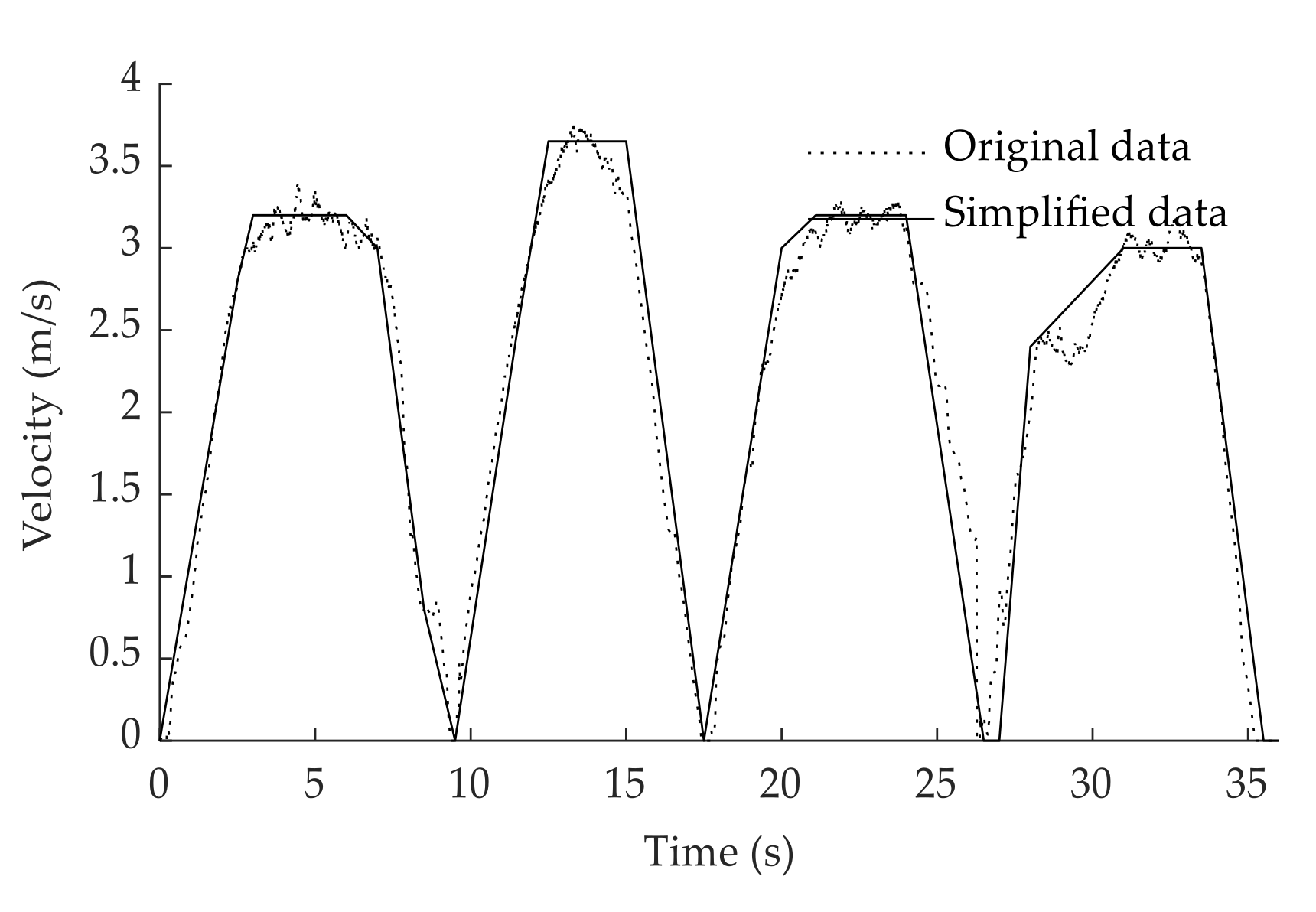
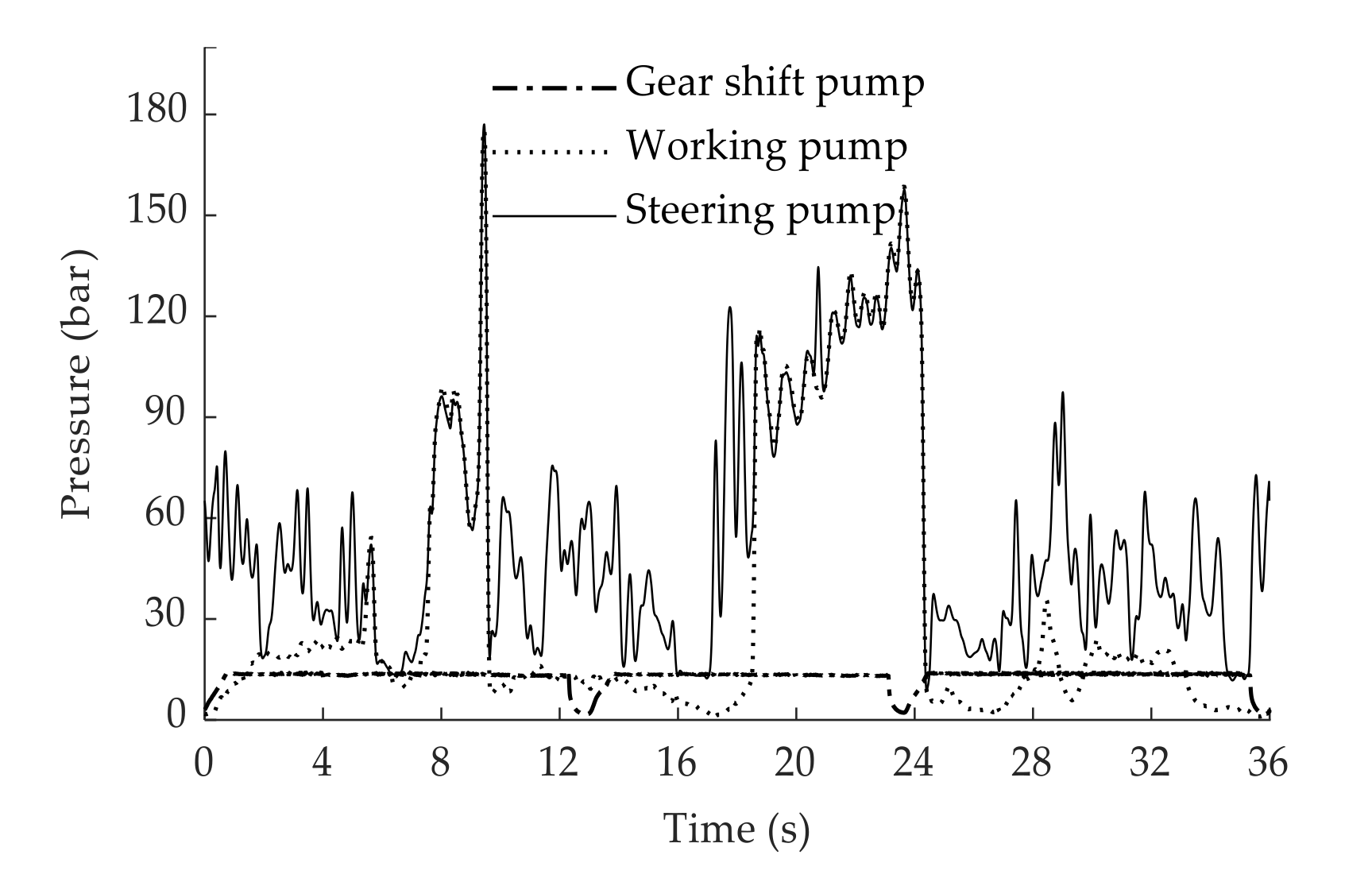
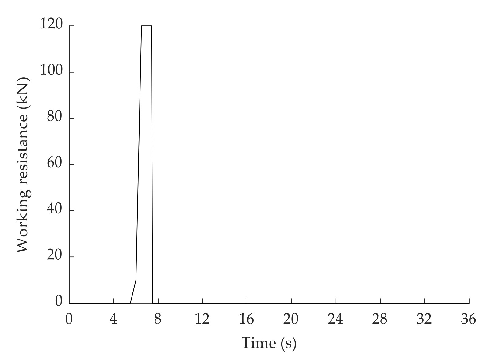
3.3. Hydraulic Load Spectrum
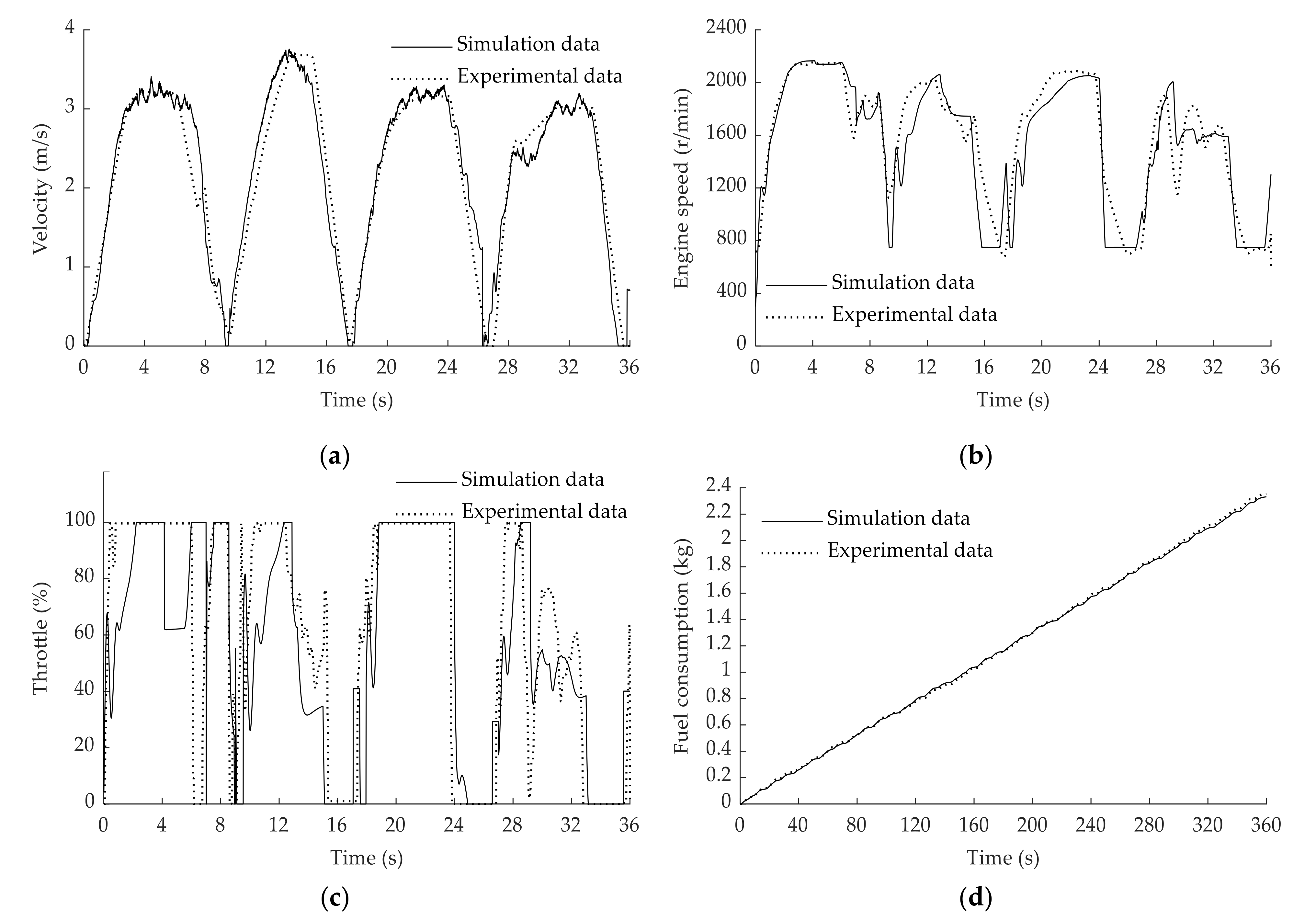
3.4. Model Calibration
4. Initial Parameter Matching
4.1. Accumulator
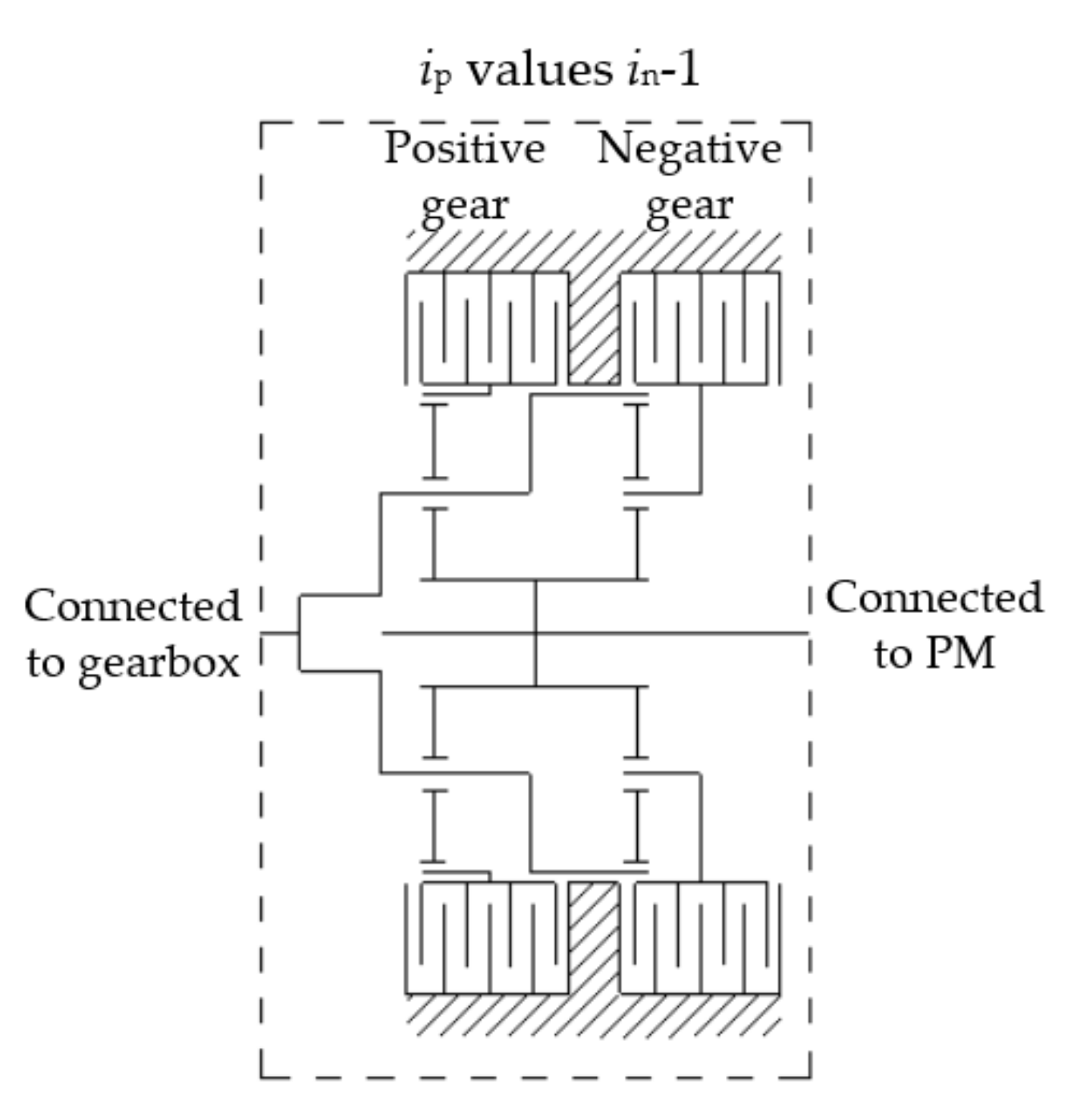
4.2. Coupler
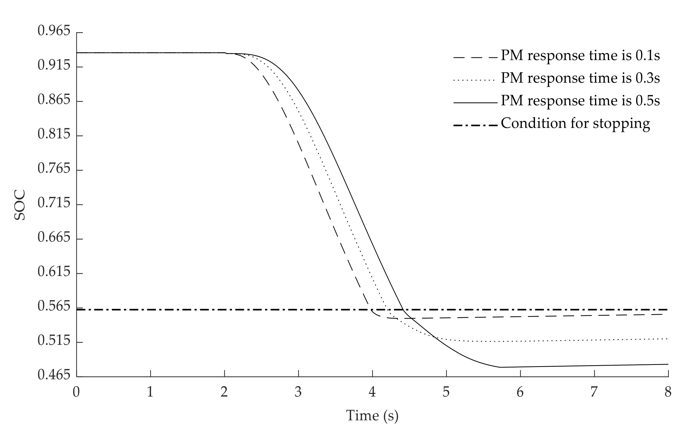
4.3. VDPM
5. Optimization
5.1. Control Strategy
- (1)
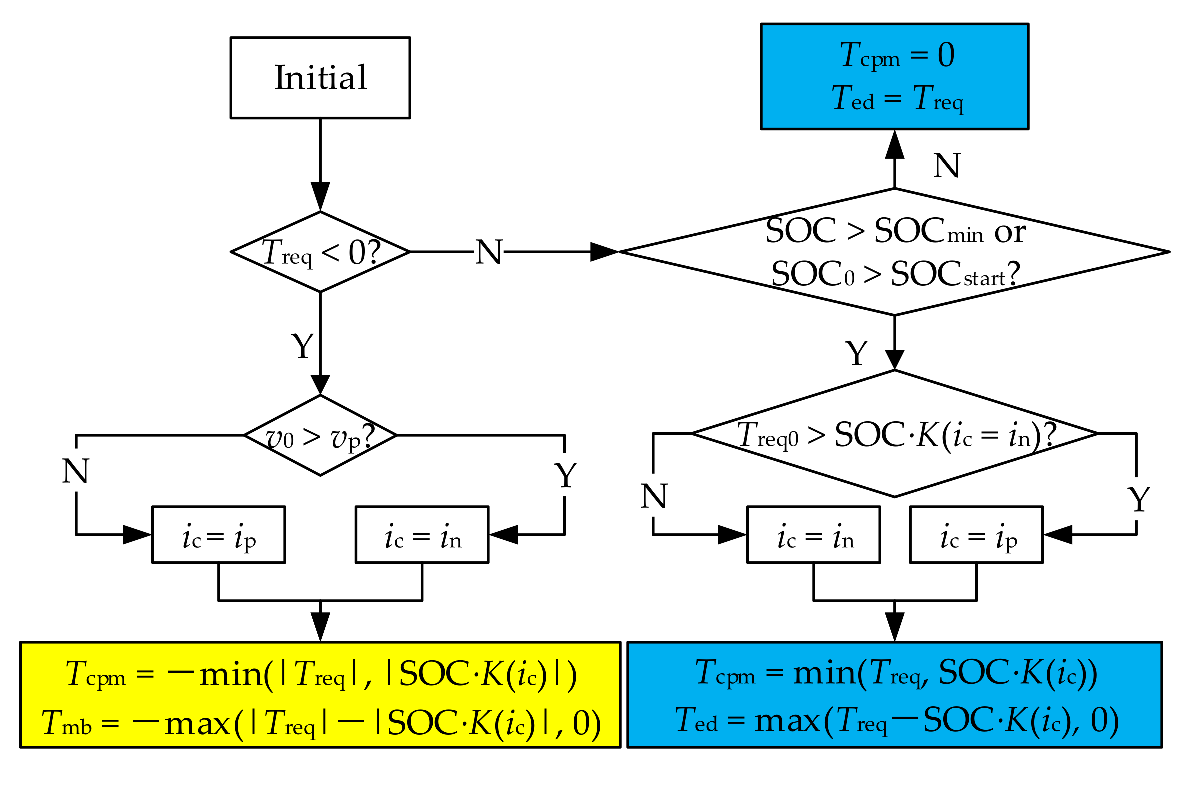
- Braking: If the initial velocity v0 is bigger than the maximum speed vp which is corresponding to the positive gear of the power coupler, the power coupler shifts negative gear (transmission ratio is in), otherwise the coupler shifts positive gear (transmission ratio is ip). Besides, the brake torque is provided by ERS prior while the insufficient part is made up by mechanical braking (Tbm is the mechanical brake torque).
- (2)
- Propelling: Firstly, if the SOC0 (initial SOC of the current propel phase) is less than the start limit SOCstart or the SOC is less than lower limit SOCmin (accumulator pressure is p1), the ERS stop working and the Treq supplied by the engine (Ted is the part of the torque driven by the engine, which is used to propel the PHHL). Secondly, if the initial demand torque of driving Treq0 is less than the drive capability of ERS at the negative gear of the coupler which is calculated by SOC and K(ic) (a coefficient related to ic), the coupler shifts negative gear, otherwise the coupler shifts positive gear. The propelling torque is provided by ERS prior while the insufficient part is made up by the engine.
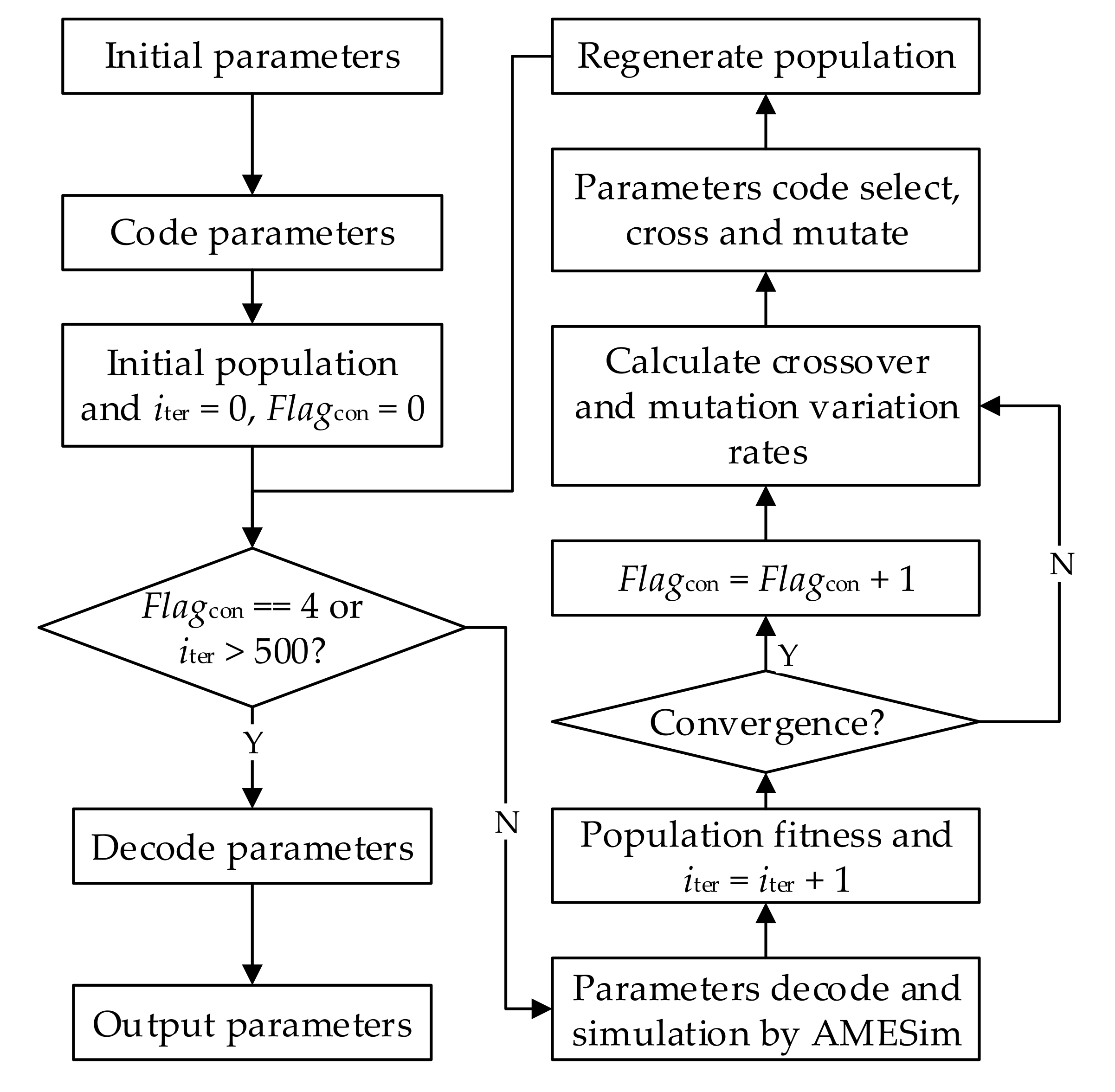
5.2. Optimization Method
- (1)
- Initial parameters: Determine the optimization parameters and their ranges;
- (2)
- Code parameters: The parameters to be optimized are digitized by binary coding method;
- (3)
- Initial population and iter = 0, Flagcon = 0: A population is initialized randomly with the population size of 20. The differences between individuals in the population are the design parameters and the control parameter (ip, p1, V0, and SOCstart) after coding. In addition, the number of iterations iter and the number of convergence Flagcon are set to 0 in this step;
- (4)
- Exit criteria: If the number of convergence Flagcon is equal to 4 or the iter is more than 500, the program goes to step (12), otherwise, the program goes to step (5);
- (5)
- Parameters decode and simulation by AMESim: The decoded individuals in the population are input into the model for simulating by AMESim;
- (6)
- Population fitness and iter = iter + 1: The fitness of the individuals in the population are calculated according to the Equation (23) and the number of iterations iter is increased by 1;
- (7)
- Convergence: The criterion for the first 3 times of convergence is that the best individual difference in 6 consecutive iterations does not exceed 0.5%, and the criterion for the last convergence is the difference in 10 consecutive iterations. If the fitness converges, the program goes to step (8), otherwise, the program goes to step (9);
- (8)
- Flagcon = Flagcon + 1: The number of convergence Flagcon is increased by 1;
- (9)
- Calculate crossover and mutation variation rates: Determine the probability of crossover and mutation variation of individuals in the population;
- (10)
- Parameters code, select, cross and mutate: The sire individuals are selected according to the fitness of individuals in the current population, and then the coded parameters are crossed and mutated according to the cross rate and mutation rate, thus the filial individuals are generated;
- (11)
- Regenerate population: Summarize the filial individuals generated in step (10) to generate a new generation of the population, then the program goes to step (4);
- (12)
- Decode parameters: Decode the optimized parameters;
- (13)
- Output parameters: Output the optimized parameters.
- (1)
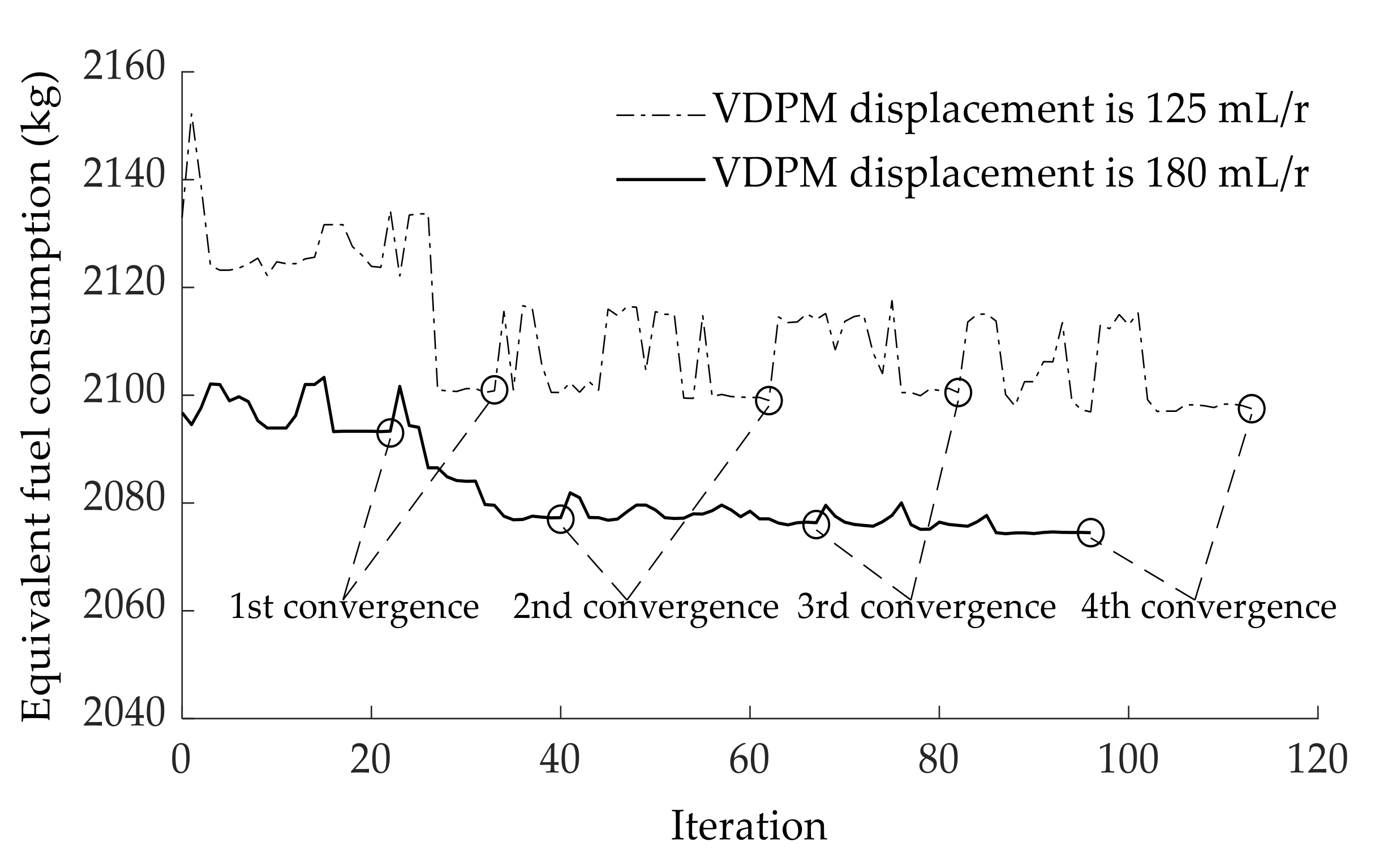
- Exit criteria: The convergence occurs four times or the iterations is more than 500;
- (2)
- The rates of crossover and mutation change with convergence.
6. Results & Discussions
6.1. Optimization Results
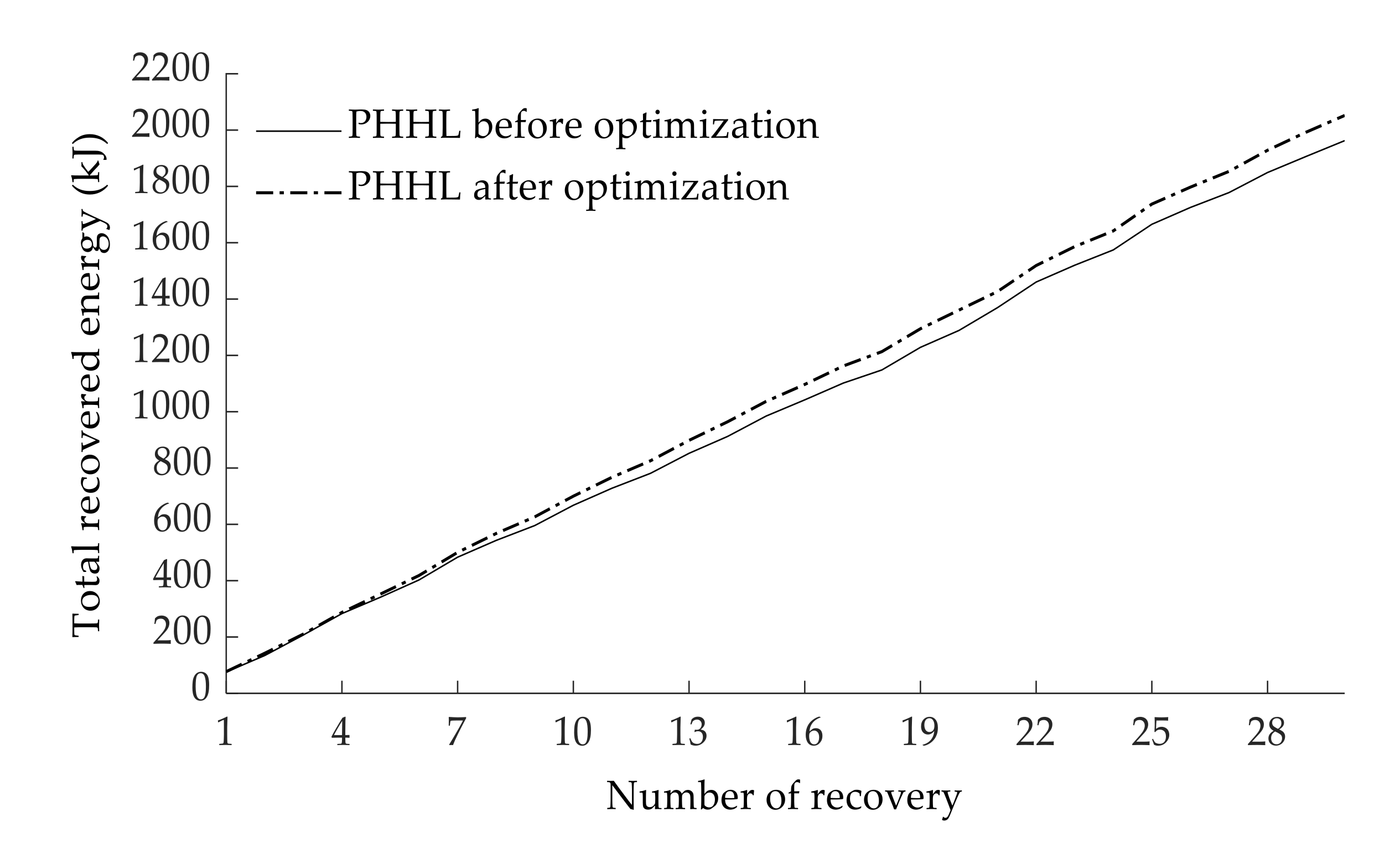
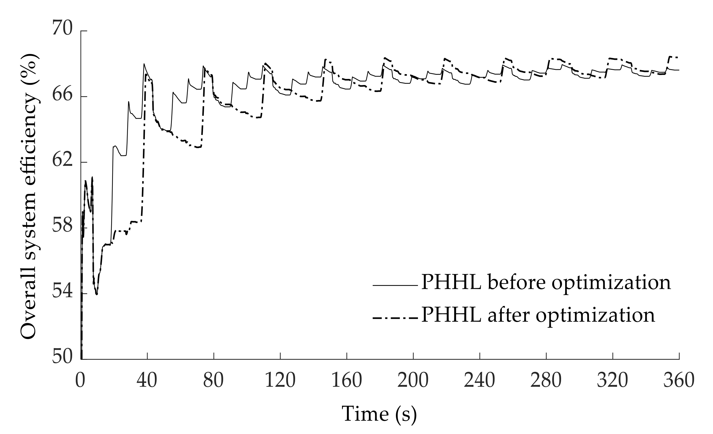
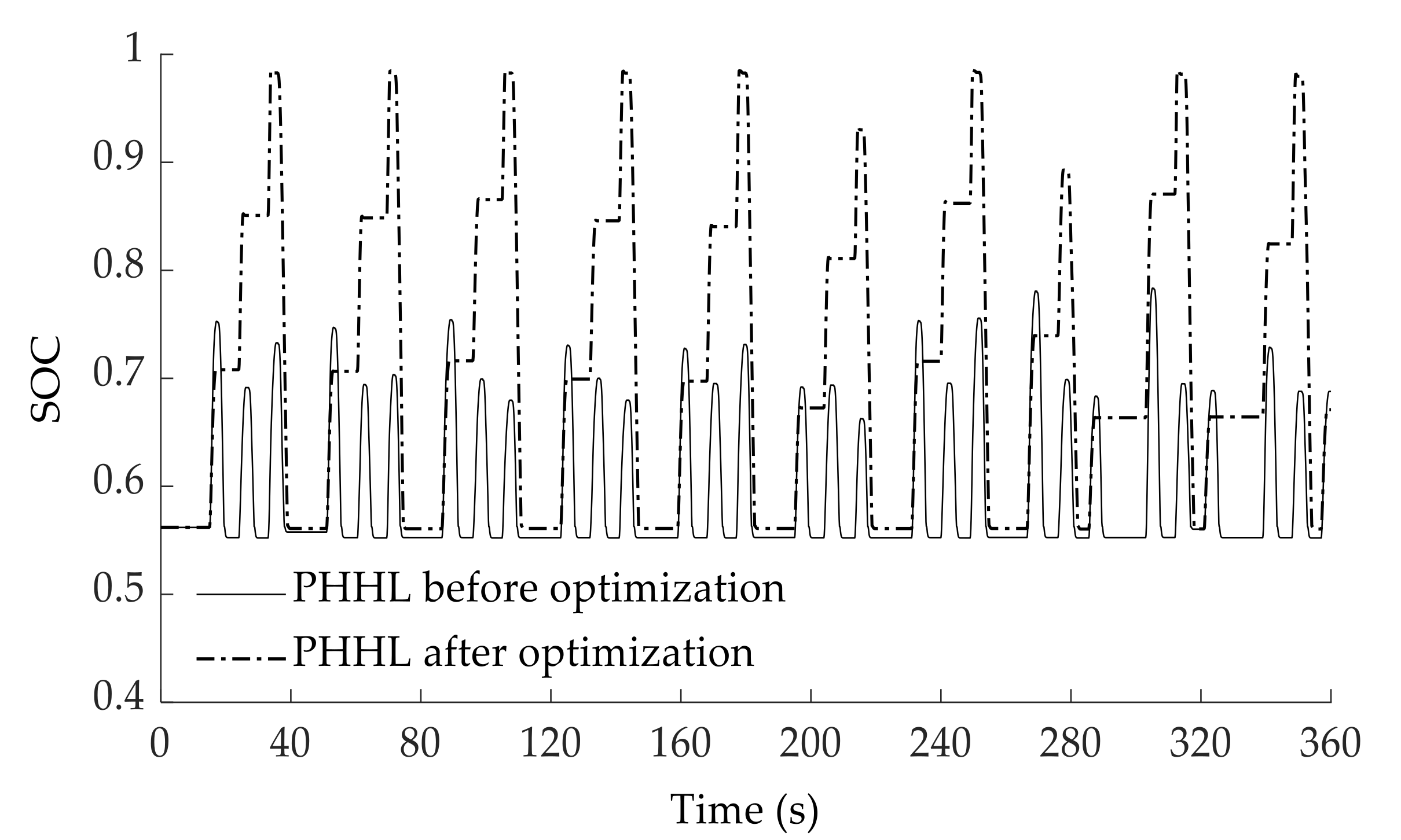
6.2. Comparison of Simulation Results before and after Optimization
6.3. Experiment
7. Conclusions
- (1)
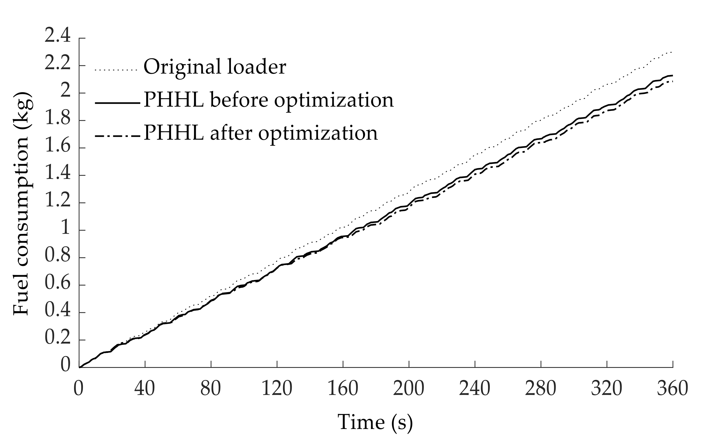
- The reduction of fuel consumption of the developed PHHL as compared to the original loader was acquired during the initial parameter matching of the ERS. Comparative analysis indicated that the fuel consumption of the developed PHHL structure was decreased by 7.44% in relation to the original loader.
- (2)
- Based on the V-type driving cycle, the optimal VDPM displacement is 180 mL/r, accumulator volume is 40 L, minimum working pressure p1 is 18 MPa, coupler transmission ratio ip is 2.73, and the optimal control variable SOCstart is 0.86. Optimization results of the PHHL demonstrated that development in fuel economy by 25% is obtained compared to that of the PHHL before optimization, which proved the effectiveness of the improved optimization algorithm.
- (3)
- The fuel consumption of the PHHL prototype and original loader was investigated by repeating the V-type duty test three times, respectively, to survey the performances of the accumulator SOC and engine operation. Control variable SOCstart is 0.88 and fuel consumption are 2.091 kg (PHHL) and 2.30 kg (original loader), which are close to simulation results. The fuel-saving is 9.12% which is close to the energy-saving potential of brake energy (around 10%). In other words, the energy-saving effect of the proposed PHHL with optimized ERS approaches the upper limit of the energy-saving effect of the PHHL based on the brake energy regeneration without additional energy-saving technologies.
Author Contributions
Funding
Data Availability Statement
Acknowledgments
Conflicts of Interest
Acronyms
| PHHL | Parallel hydraulic hybrid loader |
| HMTS | Hydrodynamic-mechanical transmission system |
| VDPM | Variable displacement pump/motor |
| PID | Proportional integral derivative |
| CAN | Controller area network |
| ERS | Energy regeneration system |
| AGA | Adaptive genetic algorithm |
| HTC | Hydraulic torque converter |
| SOC | State of charge |
| ECU | Electronic control unit |
References
- Wang, T.; Liu, H.; Han, L. Dynamic matching of Dual-Mode Electro-Mechanical Transmission (EMT) based on the optimal motor efficiency. Energy Procedia 2017, 105, 2753–2758. [Google Scholar] [CrossRef]
- Chao, Y.; Siyu, D.; Liang, L.; Sixong, Y.; Yiyong, Y.; Yue, Z. Adaptive real-time optimal energy management strategy based on equivalent factors optimization for plug-in hybrid electric vehicle. Appl. Energy 2017, 203, 883–896. [Google Scholar]
- Mu, Y.; Zhou, G.; Hou, D.; Zhu, M.; Xu, Y.; Song, N.; Gao, J. Parameter Matching and Simulation of Plug-in Hybrid Electric Bus. In Proceedings of the 2nd IEEE International Conference on Information Systems and Computer Aided Education (ICISCAE), Dalian, China, 28–30 September 2019; pp. 446–451. [Google Scholar]
- Borthakur, S.; Subramanian, S.C. Parameter matching and optimization of a series hybrid electric vehicle powertrain system. In Proceedings of the ASME 2016 International Mechanical Engineering Congress and Exposition (IMECE), Phoenix, AZ, USA, 11–17 November 2016. [Google Scholar]
- Alhejji, A.; Kuriqi, A.; Jurasz, J.; Abo-Elyousr, F.K. Energy Harvesting and Water Saving in Arid Regions via Solar PV Accommodation in Irrigation Canals. Energies 2021, 14, 2620. [Google Scholar] [CrossRef]
- Aboagye, B.; Gyamfi, S.; Antwi, E.O.; Sinisa, D. Status of renewable energy resources for electricity supply in Ghana. Sci. Afr. 2020, 11, e00660. [Google Scholar]
- Kuriqi, A.; Pinheiro, A.N.; Sordo-Ward, A.; María, D.B.; Luis, G. Ecological impacts of run-of-river hydropower plants—Current status and future prospects on the brink of energy transition. Renew. Sustain. Energy Rev. 2021, 142, 110833. [Google Scholar] [CrossRef]
- Kara, S.E.; Ibrahim, M.D.; Daneshvar, S. Dual Efficiency and Productivity Analysis of Renewable Energy Alternatives of OECD Countries. Sustainability 2021, 13, 7401. [Google Scholar] [CrossRef]
- Kuriqi, A.; Pinheiro, A.N.; Sordo-Ward, A.; Garrote, L. Influence of hydrologically based environmental flow methods on flow alteration and energy production in a run-of-river hydropower plant. J. Clean. Prod. 2019, 232, 1028–1042. [Google Scholar] [CrossRef]
- Wang, H.; Wang, Q. Parameter Matching and Control of Series Hybrid Hydraulic Excavator Based on Electro-Hydraulic Composite Energy Storage. IEEE Access 2020, 8, 111899–111912. [Google Scholar] [CrossRef]
- Yang, Y.; Luo, C.; Li, P. Design and performance analysis on a new electro-hydraulic hybrid transmission system. Int. J. Electr. Hybrid Veh. 2017, 9, 134–150. [Google Scholar] [CrossRef]
- Zhang, C.; Wang, D.; Wang, B.; Tong, F. Battery degradation minimization-oriented hybrid energy storage system for electric vehicles. Energies 2020, 13, 246. [Google Scholar] [CrossRef] [Green Version]
- Yuping, Z. Research on the parameter matching and CVT’s target speed ratio optimization of plug in hybrid electric vehicle. In Proceedings of the 2017 IEEE Transportation Electrification Conference and Expo, Asia-Pacific (ITEC Asia-Pacific), Harbin, China, 7–10 August 2017; p. 6. [Google Scholar]
- Song, P.; Lei, Y.; Fu, Y. Multi-objective optimization and matching of power source for PhEV based on genetic algorithm. Energies 2020, 13, 1127. [Google Scholar] [CrossRef] [Green Version]
- Gao, J.; Wei, Y.; Liu, Z.; Qiao, H.B. Matching and Optimization for Powertrain System of Parallel Hybrid Electric Vehicle. Appl. Mech. Mater. 2013, 341, 423–431. [Google Scholar] [CrossRef]
- Zeng, X.; Peng, Y.; Song, D. Powertrain parameter matching of a plug-in hybrid electric vehicle. In Proceedings of the 2014 IEEE Transportation Electrification Conference and Expo, ITEC Asia-Pacific 2014, Beijing, China, 31 August–3 September 2014. [Google Scholar]
- Yang, Y.; Cui, W.-L.; Su, L.; Zhao, X. Matching design and performance simulation of a new hybrid powertrain. China J. Highw. Transp. 2014, 27, 111–118. [Google Scholar]
- Chen, Q.; Shu, H.; Wang, K. Study on powertrain system for CNG-electric hybrid city bus. J. Mech. Sci. Technol. 2014, 28, 4283–4289. [Google Scholar] [CrossRef]
- Shen, Y.; Cui, P.; Wang, X.; Han, X.; Wang, Y.X. Variable structure battery-based fuel cell hybrid power system and its incremental fuzzy logic energy management strategy. Int. J. Hydrog. Energy 2020, 45, 12130–12142. [Google Scholar] [CrossRef]
- Qi, J.; Fu, J.; Jin, J. Parameter matching and sensitivity analysis for the powertrain system of micro-electric vehicle. Int. J. Electr. Hybrid Veh. 2019, 11, 23–35. [Google Scholar] [CrossRef]
- Zhao, Y.; Li, J. Parameter matching of powertrain in a plug-in hybrid electric vehicle. J. Basic Sci. Eng. 2011, 19, 459–465. [Google Scholar]
- Zhang, Y.; Mou, Y.; Yang, Z. An Energy Management Study on Hybrid Power of Electric Vehicle Based on Aluminum Air Fuel Cell. IEEE Trans. Appl. Supercond. 2016, 26, 1–6. [Google Scholar] [CrossRef]
- Lai, L.; Lu, Y.; Guo, W.; Lin, Y.; Xie, Y.; Zheng, L.; Chen, W.; Liang, B. Research on Fuel Cell and Battery Hybrid Bus System Parameters Based on ADVISOR; You, Z., Xiao, J., Tan, Z., Eds.; AIP Publishing LLC: Melville, NY, USA, 2018. [Google Scholar]
- Wang, W.; Wang, Q.-N.; Tian, Y.-J.; Wang, R.G.; Wen, Q. Control strategy for compound power slit hybrid electric bus based on fuzzy control. J. Jilin Univ. Eng. Technol. Ed. 2017, 47, 337–343. [Google Scholar]
- Wang, X.; He, H.; Tang, H.; Qin, H.Z.; Peng, J.K. Study on powertrain matching based on driving cycle for hybrid electric vehicle. In Proceedings of the 2013 International Conference on Advanced Mechanical Engineering, AME 2013, Wuhan, China, 2–3 February 2013; pp. 175–182. [Google Scholar]
- Hu, J.; Zu, G.; Jia, M.; Niu, X. Parameter matching and optimal energy management for a novel dual-motor multi-modes powertrain system. Mech. Syst. Signal Process. 2019, 116, 113–128. [Google Scholar] [CrossRef]
- Gao, S.-A.; Wang, X.; He, H.; Guo, H.Q.; Tang, H.L. Powertrain matching based on driving cycle for fuel cell hybrid electric vehicle. In Proceedings of the 2013 International Conference on Advanced Mechanical Engineering, AME 2013, Wuhan, China, 2–3 February 2013; pp. 142–147. [Google Scholar]
- Zhu, Z.; Li, C.; Tian, Y.; Wei, Q. Parametric Matching and Simulation Analysis of the Series-parallel Hybrid Electric Vehicle. In Proceedings of the 5th IEEE Information Technology and Mechatronics Engineering Conference, ITOEC 2020, Chongqing, China, 12–14 June 2020; pp. 325–329. [Google Scholar]
- Smith, R.; Shahidinejad, S.; Blair, D.; Bibeau, E.L. Characterization of urban commuter driving profiles to optimize battery size in light-duty plug-in electric vehicles. Transp. Res. Part D Transp. Environ. 2011, 16, 218–224. [Google Scholar] [CrossRef]
- Chu, L.; Yin, J.; Yao, L.; Wang, W. The method for matching the PMSM’s base parameters of the Hybrid Electric Vehicle based on drive cycle. In Proceedings of the 2011 International Conference on Electronic and Mechanical Engineering and Information Technology, EMEIT 2011, Harbin, China, 12–14 August 2011; pp. 3234–3237. [Google Scholar]
- Fu, X.; Zhang, Q.; Tang, J.; Wang, C. Parameter Matching Optimization of a Powertrain System of Hybrid Electric Vehicles Based on Multi-Objective Optimization. Electronics 2019, 8, 875. [Google Scholar] [CrossRef] [Green Version]
- Wang, C.; Huang, B.; Xu, W. An Integrated Energy Management Strategy with Parameter Match Method for Plug-in Hybrid Electric Vehicles. IEEE Access 2018, 6, 62204–62214. [Google Scholar] [CrossRef]
- Zhang, W.; Yang, J.; Zhang, W.; Ma, F. A Research on Hybrid Energy Storage System for Battery Electric Mining Trucks. Qiche Gongcheng Automot. Eng. 2019, 41, 641–646, 653. [Google Scholar]
- Zhang, L.; Zeng, X.-H.; Guo, K.-H.; Wang, Y.; Song, D.F. Design of Hybrid Energy Storage System for Power-Split Hybrid Electric Vehicle. Trans. Beijing Inst. Technol. 2017, 37, 478–484. [Google Scholar]
- Quan, R.; Wang, C.; Wu, F.; Chang, Y.; Deng, Y. Parameter Matching and Optimization of an ISG Mild Hybrid Powertrain Based on an Automobile Exhaust Thermoelectric Generator. J. Electron. Mater. 2020, 49, 2734–2746. [Google Scholar] [CrossRef]
- Wang, Y.; Sun, D. Powertrain Matching and Optimization of Dual-Motor Hybrid Driving System for Electric Vehicle Based on Quantum Genetic Intelligent Algorithm. Discret. Dyn. Nat. Soc. 2014, 2014, 956521. [Google Scholar] [CrossRef]
- Chen, P.-T.; Pai, P.-H.; Yang, C.-J.; Huang, K.D. Development of Transmission Systems for Parallel Hybrid Electric Vehicles. Appl. Sci. Basel 2019, 9, 1538. [Google Scholar] [CrossRef] [Green Version]
- Lai, L.; Chang, T.-C. Research and optimization fuel cell and battery hybrid bus system parameters based on genetic algorithm. Microsyst. Technol. MicroNanosyst. Inf. Storage Process. Syst. 2019, 27, 1827–1836. [Google Scholar]
- Wu, X.; Hu, X.; Yin, X.; Li, L.; Zeng, Z.; Pickert, V. Convex programming energy management and components sizing of a plug-in fuel cell urban logistics vehicle. J. Power Sources 2019, 423, 358–366. [Google Scholar] [CrossRef]
- Jiang, X.; Hu, J.; Jia, M.; Zheng, Y. Parameter matching and instantaneous power allocation for the hybrid energy storage system of pure electric vehicles. Energies 2018, 11, 1933. [Google Scholar] [CrossRef] [Green Version]
- Chen, Z.; Zhou, L.; Sun, Y.; Ma, Z.; Han, Z. Multi-objective parameter optimization for a single-shaft series-parallel plug-in hybrid electric bus using genetic algorithm. Sci. China Technol. Sci. 2016, 59, 1176–1185. [Google Scholar] [CrossRef]
- Borthakur, S.; Subramanian, S.C. Design and optimization of a modified series hybrid electric vehicle powertrain. Proc. Inst. Mech. Eng. Part D J. Automob. Eng. 2019, 233, 1419–1435. [Google Scholar] [CrossRef]
- Borthakur, S.; Subramanian, S.C. Optimized Design and Analysis of a Series-Parallel Hybrid Electric Vehicle Powertrain for a Heavy Duty Truck. IFAC-PapersOnLine 2018, 51, 184–189. [Google Scholar] [CrossRef]
- Zhao, P.; Chen, Y.; Zhou, H. Potential energy recovery system of hydraulic hybrid excavator. In Proceedings of the BATH/ASME 2016 Symposium on Fluid Power and Motion Control, FPMC 2016, Bath, UK, 7–9 September 2016. [Google Scholar]
- Chen, Q.; Lin, T.; Ren, H. Parameters optimization and control strategy of power train systems in hybrid hydraulic excavators. Mechatronics 2018, 56, 16–25. [Google Scholar] [CrossRef]
- Li, T.-Y.; Zhao, D.-X.; Kang, H.-L.; Zhang, Z.W.; Zhang, Z.F.; Xu, C.B. Parameter matching of parallel hybrid power loaders. J. Jilin Univ. Eng. Technol. Ed. 2013, 43, 916–921. [Google Scholar]
- Lai, X.; Guan, C. A parameter matching method of the parallel hydraulic hybrid excavator optimized with genetic algorithm. Math. Probl. Eng. 2013, 2013, 765027. [Google Scholar] [CrossRef]
- Jing, Z. Analysis and Matching Calculation of Hydraulic Drive System of Tractor. J. Phys. Conf. Series. 2020, 1676, 012211. [Google Scholar] [CrossRef]
- Lin, T.; Tan, Z.; He, Z.; Cao, H.; Lv, H.S. Analysis of influencing factors on transient temperature field of wet clutch friction plate used in marine gearbox. Ind. Lubr. Tribol. 2018, 70, 241–249. [Google Scholar] [CrossRef]
- Cheng, D. Mechanical Design Manual; Chemical Industry Press: Beijing, China, 2008. [Google Scholar]
- Yaws, C.L. Chemical Properties Handbook; McGraw-Hill Education: New York, NY, USA, 1999. [Google Scholar]
- Wang, Y.; Gao, D. Technical Manual for Hydraulic Engineers; Chemical Industry Press: Beijing, China, 2010. [Google Scholar]
- Zhu, Z.; Gao, X.; Cao, L.; Pan, D.; Zhu, Y.; Guo, J. Research on Response Characteristic and Efficiency Characteristic of Pump-control-motor System. Mach. Tool Hydraul. 2016, 44, 87–90. [Google Scholar]
- Li, T.; Liu, H.; Zhao, D.; Wang, L. Design and analysis of a fuel cell supercapacitor hybrid construction vehicle. Int. J. Hydrog. Energy 2016, 41, 12307–12319. [Google Scholar] [CrossRef]
- Fan, W.J. Research on movement and energy loss characteristics of wheel loader with co-simulation and experiment. Taiyuan Univ. Technol. 2014. Available online: https://d.wanfangdata.com.cn/thesis/Y2693552 (accessed on 12 August 2021).
- Lin, T.L.; Liu, Q. Method of Parameter Matching for Hydraulic Hybrid System for Excavators. J. Shanghai Jiaotong Univ. 2013, 47, 48–51. [Google Scholar]
- Grammatico, S.; Balluchi, A.; Cosoli, E. A series-parallel hybrid electric powertrain for industrial vehicles. In Proceedings of the 2010 IEEE Vehicle Power and Propulsion Conference, Lille, France, 1–3 September 2010. [Google Scholar]
- Li, T.; Liu, H.; Ding, D. Predictive energy management of fuel cell supercapacitor hybrid construction equipment. Energy 2018, 149, 718–729. [Google Scholar] [CrossRef]
- Wang, J.; Yang, Z.; Liu, S.; Zhang, Q.; Han, Y. A comprehensive overview of hybrid construction machinery. Adv. Mech. Eng. 2016, 8, 1687814016636809. [Google Scholar] [CrossRef] [Green Version]


| Parameter Description | Symbol | Value | Unit |
|---|---|---|---|
| Operating weight | mo | 17,300 | kg |
| Rated load | mL | 5000 | kg |
| Engine rated power | Pe | 162 | kW |
| Engine rated speed | ne | 2000 | r/min |
| torque ratio | Ktc | 4 ± 0.2 | — |
| Transmission ratio (first/second/reverse) | ig | 2.547/0.683/1.864 | — |
| Transmission ratio of the main drive | imd | 4.625 | — |
| Transmission ratio of hub reducer | ihr | 4.928 | — |
| Tire power radius | rw | 0.76 | m |
| Displacement of the steering pump | Dsp | 83.6 | mL/r |
| Displacement of working pump | Dwp | 100 | mL/r |
| Displacement of change pump | Dcp | 60 | mL/r |
| Working Condition | Maximum Velocity (km/h) | Bs1 (m/s2) | Bs2 (m/s2) |
|---|---|---|---|
| No load 1st shift | 11.84 | 1.55 | — |
| Full load 1st shift | 11.79 | 1.23 | 1.55 |
| No load 2nd shift | 41.02 | 3.69 | — |
| Full load 2nd shift | 38.96 | 1.84 | — |
| No load reverse shift | 16.10 | 2.07 | 1.7 |
| Full load reverse shift | 15.92 | 1.56 | 1.8 |
| Working Condition | Barke Strength (Unit: m/s2) for VDPM with Different Displacements (Unit: mL/r) | ||||
|---|---|---|---|---|---|
| 40 | 71 | 125 | 180 | 250 | |
| No load 1st shift | 1.05 | 1.45 | 1.98 | 2.64 | 3.09 |
| Full load 1st shift | 0.87 | 1.18 | 1.59 | 2.10 | 2.46 |
| No load 2nd shift | 0.5 | 0.62 | 0.79 | 1 | 1.14 |
| Full load 2nd shift | 0.44 | 0.54 | 0.67 | 0.83 | 0.94 |
| No load reverse shift | 0.92 | 1.27 | 1.71 | 2.27 | 2.65 |
| Full load reverse shift | 0.77 | 1.04 | 1.39 | 1.82 | 2.12 |
| Shift of Gearbox | Maximum Transmission Ratio of Coupler for Different VDPM Displacements (Unit: mL/r) | ||||
|---|---|---|---|---|---|
| 40 | 71 | 125 | 180 | 250 | |
| First | 4.9597 | 4.1847 | 3.4098 | 3.2548 | 2.7898 |
| Second | 1.5737 | 1.3278 | 1.0819 | 1.0328 | 0.8852 |
| Reverse | 4.1966 | 3.5409 | 2.8852 | 2.7540 | 2.3606 |
| DPM (mL/r) | ip | p1 (MPa) | V0 (L) | SOCstart | Minimum Fuel Consumption (kg) |
|---|---|---|---|---|---|
| 125 | 2.89 | 23 | 45 | 0.91 | 2.107 |
| 180 | 2.73 | 18 | 40 | 0.86 | 2.085 |
| Item | Fuel Consumption (kg) | Fuel Saving (%) | DPM (mL/r) | ip | V0 (L) |
|---|---|---|---|---|---|
| Original loader | 2.299 | — | — | — | — |
| PHHL before optimization | 2.128 | 7.44% | 180 | 2.76 | 30 |
| PHHL after optimization | 2.085 | 9.31% | 180 | 2.73 | 40 |
| Parameter Description | Symbol | Value | Unit |
|---|---|---|---|
| VDPM displacement | DPM | 180 | mL/r |
| Accumulator volume | V0 | 40 | L |
| Accumulator inflation pressure | p0 | 12 | MPa |
| Accumulator minimum working pressure | p1 | 18 | MPa |
| Coupler transmission ratio (positive/ negative) | ic | 3.73/2.73 | — |
| Item | Fuel Consumption | Average Fuel Consumption | Fuel Saving | Simulation Err |
|---|---|---|---|---|
| Original loader | 2.309 kg | 2.3 kg | — | — |
| 2.254 kg | ||||
| 2.337 kg | ||||
| PHHL | 2.048 kg | 2.091 kg | 9.12% | 2.04% |
| 2.098 kg | ||||
| 2.126 kg |
Publisher’s Note: MDPI stays neutral with regard to jurisdictional claims in published maps and institutional affiliations. |
© 2021 by the authors. Licensee MDPI, Basel, Switzerland. This article is an open access article distributed under the terms and conditions of the Creative Commons Attribution (CC BY) license (https://creativecommons.org/licenses/by/4.0/).
Share and Cite
Yang, J.; Bian, Y.; Yang, M.; Shao, J.; Liang, A. Parameter Matching of Energy Regeneration System for Parallel Hydraulic Hybrid Loader. Energies 2021, 14, 5014. https://doi.org/10.3390/en14165014
Yang J, Bian Y, Yang M, Shao J, Liang A. Parameter Matching of Energy Regeneration System for Parallel Hydraulic Hybrid Loader. Energies. 2021; 14(16):5014. https://doi.org/10.3390/en14165014
Chicago/Turabian StyleYang, Jixiang, Yongming Bian, Meng Yang, Jie Shao, and Ao Liang. 2021. "Parameter Matching of Energy Regeneration System for Parallel Hydraulic Hybrid Loader" Energies 14, no. 16: 5014. https://doi.org/10.3390/en14165014
APA StyleYang, J., Bian, Y., Yang, M., Shao, J., & Liang, A. (2021). Parameter Matching of Energy Regeneration System for Parallel Hydraulic Hybrid Loader. Energies, 14(16), 5014. https://doi.org/10.3390/en14165014