Article

Analysis of an IPMSM Hybrid Magnetic Equivalent Circuit

1
Department of Electrical Engineering, Hanbat National University, Daejeon 31458, Korea
2
Division of Eco-Friendly Vehicle R&D, Korea Automotive Technology Institute, Cheonan 31214, Korea
*
Author to whom correspondence should be addressed.
Energies 2021, 14(16), 5011; https://doi.org/10.3390/en14165011
Submission received: 29 June 2021 / Revised: 30 July 2021 / Accepted: 13 August 2021 / Published: 15 August 2021

Abstract

:
The most common type of electric vehicle traction motor is the interior permanent magnet synchronous motor (IPMSM). For IPMSM designs, engineers make use of the magnetic equivalent circuit method, which is a lumped constant circuit method, and the finite element method, which is a distributed constant circuit method. The magnetic equivalent circuit method is useful for simple design through fast and intuitive parameters, but it cannot derive the distribution of the magnetic field. The finite element method can derive an accurate magnetic field distribution, but it takes a long time and is difficult to use for analysis of intuitive design parameters. In this study, the magnetic equivalent circuit method and Carter’s coefficient were combined for rotor structure design and accurate identification and analysis of circuit constants. In this paper, this design method is called the hybrid magnetic equivalent circuit method. Intuitive design parameters are derived through this hybrid magnetic equivalent circuit method. The air gap flux density distribution according to rotor shape, no-load-induced voltage, and cogging torque was analyzed and compared to results of the finite element method. The proposed method was found to achieve a short solving time and acceptably accurate results.

1. Introduction

Recently, the demand for electric vehicles (EVs) has increased worldwide in response to eco-friendly policies and stricter emission regulations. The traction motor for most EVs is the interior permanent magnet synchronous motor (IPMSM) [1,2,3,4]. The IPMSM field does not require an excitation current because a permanent magnet is used. Thus, the rotor loss is lower than that of other motors and high-efficiency operation is possible. In addition, the output density is higher than that of other motors because magnetic torque using the arranging force of the field and armature occurs at the same time as the reluctance torque using the salient polarity of the rotor. Furthermore, a wide operating range is made possible by its field-weakening operation characteristics. Because of these characteristics, an IPMSM has multiple ratings and is suitable as a traction motor for EVs, which require maximum distance traveled on one battery charge (or range). At the same speed, high torque in the motor indicates high output; thus, torque is a parameter that determines the EV’s range. On the other hand, torque ripple is a source of electrical noise and vibration and therefore is a factor that affects driver and passenger riding comfort [5,6,7,8].
IPMSMs have two operation areas. One is a constant-torque range, and the other is a constant-output operation range. The change in this range is quite diverse depending on the motor design method [9,10,11]. To design EV IPMSMs, engineers mainly use the magnetic equivalent circuit method, which is a lumped constant circuit method, and the finite element method (FEM), which is a distributed constant circuit method. In the magnetic equivalent circuit, the maximum speed, demagnetization details, and maximum torque are simply determined by obtaining the flux per pole, d-axis inductance, and q-axis inductance. After the simple design, the final design is made in consideration of torque ripple, cogging torque, and voltage containing harmonic components with respect to the spatial and temporal magnetic field changes through the FEM, the spatial harmonic method, and other methods.
The magnetic equivalent circuit method is useful for simple design through fast and intuitive parameters but cannot derive the magnetic field distribution. The FEM can derive an accurate magnetic field distribution, but it takes a long time, and it is difficult to analyze intuitive design parameters. Many studies have analyzed the magnetic field distribution in the air gap using an analytical circuit model to predict accuracy results [12,13,14]. To provide intuitive solutions in extremely short times, field quantities such as leakage flux paths and saturation, which are important in iron loss calculations, are evaluated using analytical circuit methods [15,16,17,18,19,20]. In addition, this analytical method can be applied to the analysis of many devices, such as transformers, DC/DC converter-coupled inductors, switched reluctance motors, and interior permanent magnet motors where saturation and losses are important [21].
The FEM is used to verify the theory and the expertise of the designer and must be used properly. In other words, the advantages and limitations of existing design techniques are clear [22,23,24,25].
In this study, the magnetic equivalent circuit method and Carter’s coefficient are mixed for rotor structure design. Carter’s coefficient helps to obtain accurate results based on defined parameters. This proposed method will be called the hybrid magnetic equivalent circuit (HMEC). It is a design method that combines the spatial harmonic method and the magnetic circuit method. It can provide accurate solution results in a shorter time than FEM, and intuitive design parameters are derived through the proposed HMEC method. Additionally, it will represent the air gap flux density distribution according to rotor shape, no-load-induced voltage, and cogging torque. In the conclusion, the proposed HMEC method is compared with the FEM method and verified that the obtained results are appropriate.

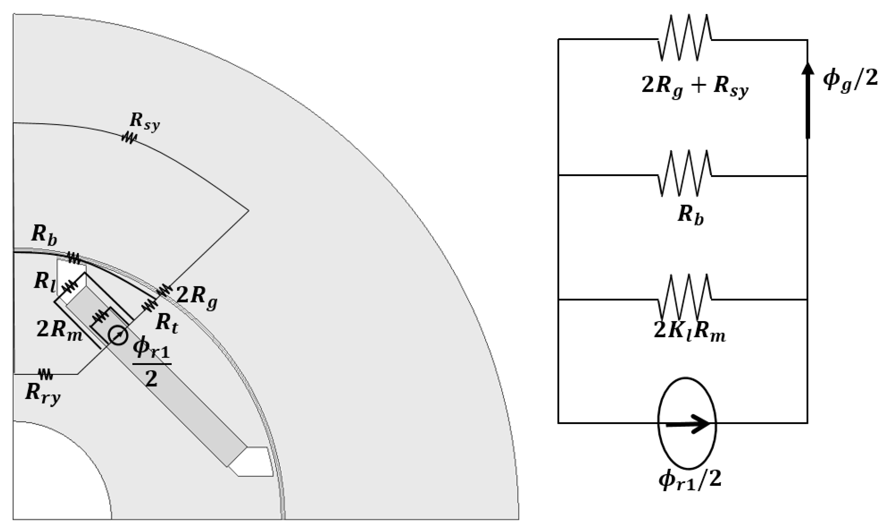
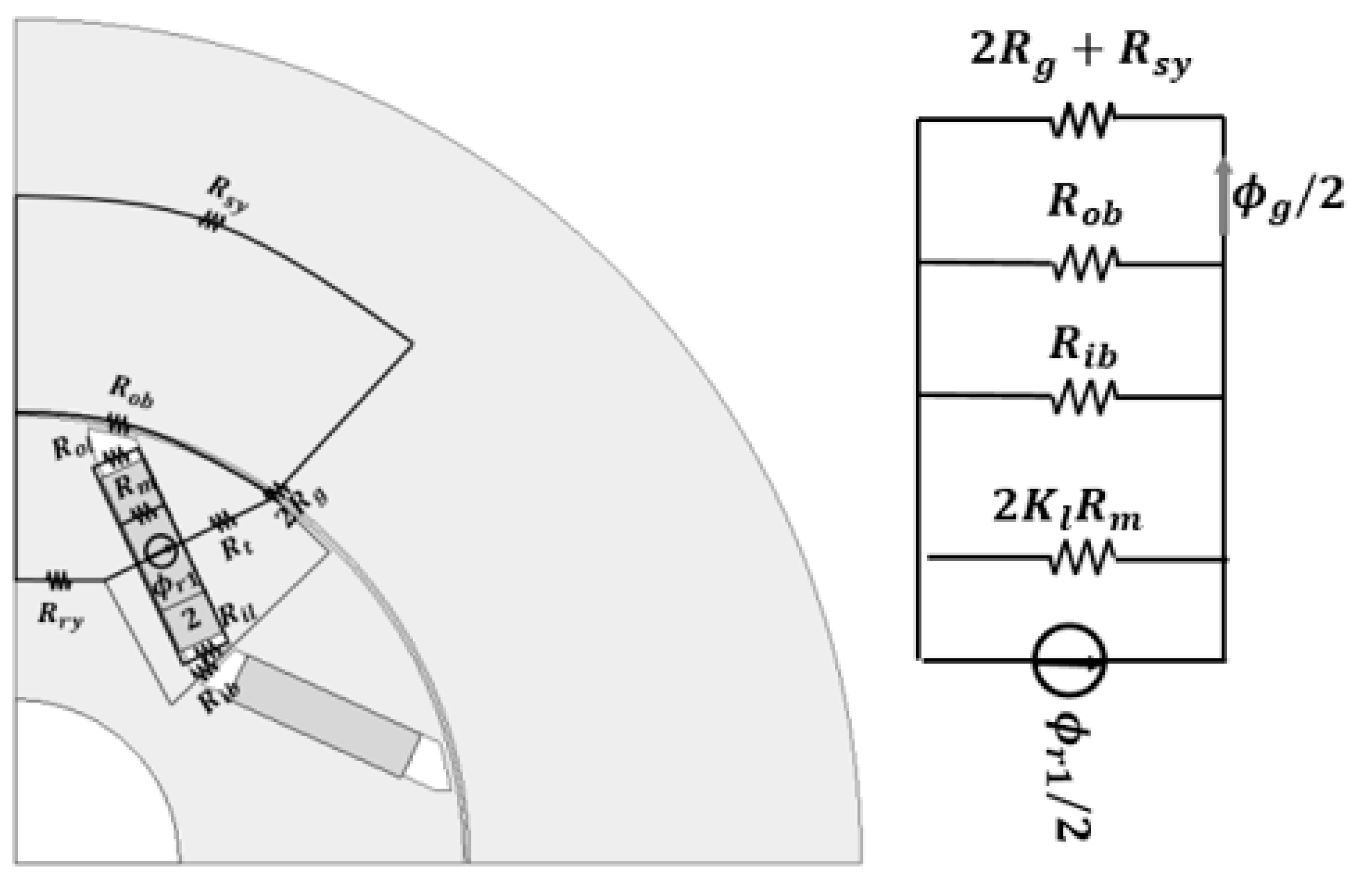
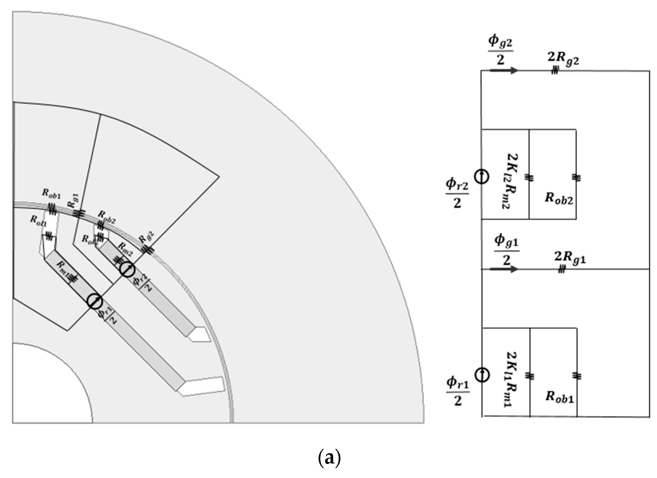
2. Proposed Magnetic Equivalent Circuit

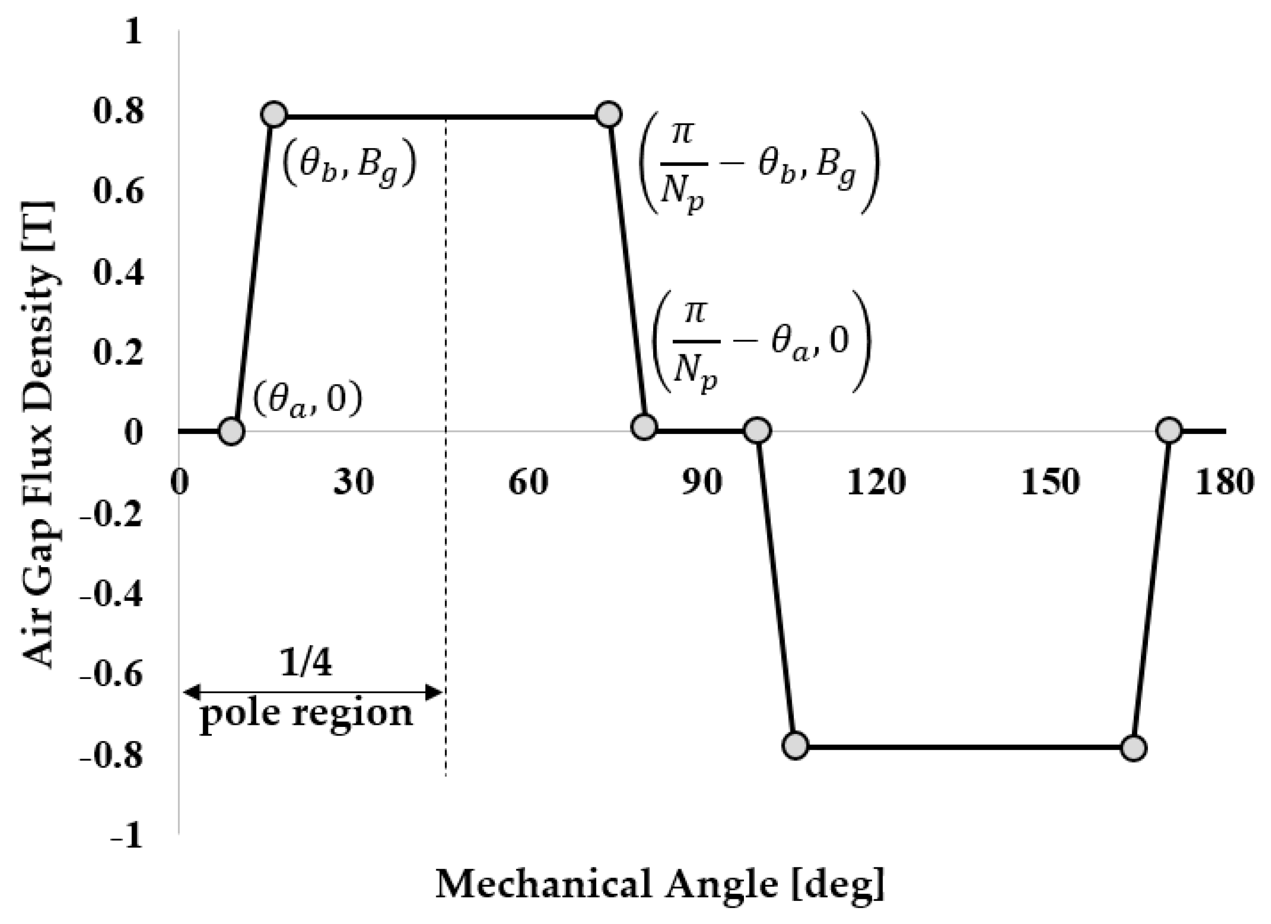
2.1. Calculation of the Slotless Air Gap Flux Density Distribution by Permanent Magnet

Figure 1 shows three regions of the slotless flux line distribution by permanent magnet. θ p , θ a , and θ b represent, respectively, the pole arc angle, the angle between the starting point of the bridge from the center of the q-axis, and the angle between the bridge start point and end point. The slotless flux line distribution by the permanent magnet has a constant value in the region of the pole arc, and the magnetic field is close to zero in the region of the q-axis magnetic path and falls constantly in the region of a bridge. Therefore, if it is treated as a line function that falls constantly in a barrier region, the function of the air flux density by permanent magnet is derived as Equation (1) and shown in Figure 2 (the slotless air gap flux density distribution). If the Fourier series is applied to the function of Equation (1), Equations (2) and (3) are derived. The average air gap flux density is derived through the magnetic equivalent circuit.
B g ( θ ) = { 0 0 θ < θ a B g θ b θ a ( θ θ a ) θ a θ < θ b B g θ b θ < π N p θ b B g θ b θ a ( θ ( π N p θ a ) ) π N p θ b θ < π N p θ a 0 π N p θ a θ < π N p
B g n = 4 B g π N p ( θ b θ a ) ( 2 n 1 ) 2 ( sin N p θ b ( 2 n 1 ) sin N p θ a ( 2 n 1 ) )
B g n ( θ , α ) = n = 1 B g n sin N p ( θ α ) ( 2 n 1 )
where B g , n , α , B g n and N p are, respectively, the average flux density of the air gap, harmonic order, angle of rotor position, Fourier coefficient of flux density, and number of poles.
Figure 3 shows the magnetic circuit of a slotless permanent magnet. The reluctance of the rotor core is quite small compared with that of the air gap, barrier, and permanent magnet, so it is neglected. Because the reluctance of the stator core is connected in series with reluctance of the air gap, as shown in Equation (4), it is treated as K r . As shown in Equation (5), the barrier leakage of the permanent magnet is treated as K l . By applying the flux distributive law, the flux equation of the air gap is derived as Equation (6). If Equation (6) is divided by the area of the air gap, the average of the air gap flux density of Equation (7) is derived.
K r = 2 R g + R s y 2 R g
K l = 2 R m | | R b l 2 R m
ϕ g = 1 2 K r R g 1 2 K r R g + 1 R b + 1 2 K l R m ϕ r
ϕ g A g = B g
where R m , R b l , R b , R g , R s y , ϕ g and ϕ r are, respectively, the reluctance of the permanent magnet, reluctance of a barrier, reluctance of a bridge, reluctance of the air gap, reluctance of the stator yoke, flux of the air gap, and residual flux.

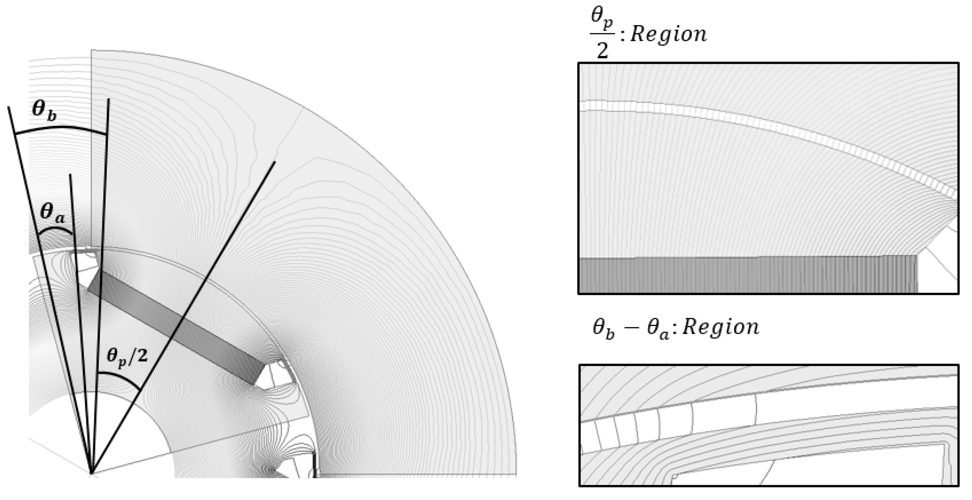
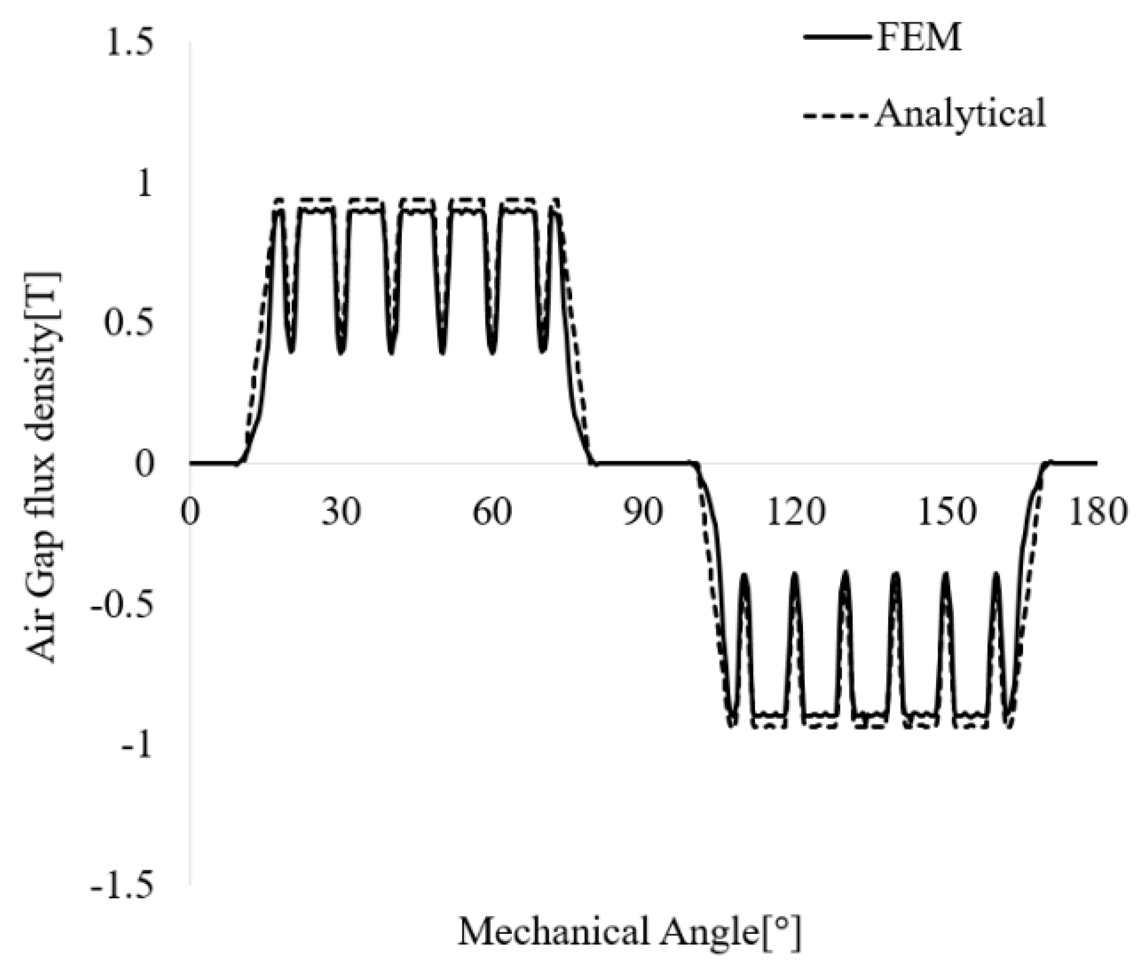
2.2. Calculation of the Air Gap Flux Density Distribution by Permanent Magnet with Slot

The structure of a motor with slots, as shown in Figure 4, is common. Figure 4 shows the flux line distribution by permanent magnets with slots. When there is a slot, the flux can be divided into two regions. One is the flux region that goes directly from the pole to the teeth, and the other is the flux region that goes from the pole to the teeth through the slot opening. The magnetic field is constant in the teeth region, but as can be seen from the flux in the slot opening region, the length of the air gap increases toward the center of the slot opening and reaches its maximum length at the center. The distribution of the slot-opening region is derived by applying the air gap length function of Carter’s coefficient. In addition, the total average air gap flux density, as shown in Equation (8), is derived through a magnetic equivalent circuit, as shown in Figure 5.
R s y = R r t = R r y = 0
R k = K r k R g k
ϕ g t o t a l = ϕ g 1 + ϕ g 2 + ϕ g 3 + ϕ g 4
B g k = P g k P t o t a l A m A g k B r
B g t o t a l = ϕ g t o t a l A g t o t a l
where R r t , R r y , P g k , P t o t a l , A m , A g k , A g t o t a l , ϕ g t o t a l and B g t o t a l are, respectively, the reluctance of the rotor teeth, reluctance of the rotor yoke, permeance of the air gap corresponding to slot k, total permeance, area of the permanent magnet, area of air gap corresponding to slot k, area of the total air gap, total flux of the air gap, and total average air gap flux density.
Figure 6 shows the air gap flux line distribution per slot when there are slots. The average air gap flux density-derived Equation (12) is the total average of both the slot-opening and the teeth region. A transformation of the equation is necessary to obtain an accurate distribution. First, the air gap flux density in the teeth region, as in Equation (14), can be obtained by multiplying Equations (12) and (13), which is the flux distributive law of the reluctance difference of the teeth and the slot-opening regions. Finally, the total air gap flux density in the teeth region is derived as Equation (15).
C t k = P g t k P g t k + 2 P g s o A g k A g t k
B g t k = C t k B g k
B g t t o t a l = ϕ g t t o t a l A g t t o a l
where C t k , P g t k , 2 P g s o , A g t k , A g t t o t a l , ϕ g t t o t a l and B g t t o t a l are a correction factor for teeth about the air gap flux density, permeance of the air gap corresponding to the stator teeth of slot k, permeance of the air gap corresponding to the slot opening of slot k, area of the stator teeth, total area of the stator teeth, total flux of the stator teeth, and total flux density of the stator teeth.
The function of the air gap length of the slot-opening region is expressed as Equation (16). In order to derive the function of the slot factor, the magnetic circuit equation obtained by functionalizing the air gap length is divided into the magnetic circuit equation before functionalization. If these equations are rearranged, the function equation of the slot factor is derived as Equation (17). However, this slot factor function does not reflect the saturation of flux density of the shoe part, as shown in Figure 7. Therefore, by applying the slot-opening range of Hanselman, the slot opening is changed to 0.7, which is larger than the actual 0.5, and the function is changed to Equation (18) [14]. The final slot factor function is derived as Equations (19) and (20). Applying this expression to the Fourier series yields Equations (21)–(23). Figure 6b shows the slot factor derived through the HMEC and FEM.
g ( θ ) g = { 1 | θ | θ t 2 1 + π 2 r s i g ( | θ | θ t ) θ t 2 | θ | < θ s p 2
G s l ( θ ) = B g t ( θ ) B g t = 1 g + 2 C t K r μ 0 A g ( 1 R b + 1 2 K l R m ) 1 g + 2 C t K r μ 0 A g ( 1 R b + 1 2 K l R m ) g ( θ ) g
θ t r 2 = θ s p 2 0.7 θ s o
G min = 1 g + 2 C t K r μ 0 A g ( 1 R b + 1 2 K l R m ) 1 g + 2 C t K r μ 0 A g ( 1 R b + 1 2 K l R m ) ( 1 + π r s i θ s o 4 g )
G s l ( θ ) = { 1 | θ | θ t r 2 1 + G min 2 + 1 G min 2 cos ( π ( | θ | 0.5 θ t r ) 0.7 θ s o ) θ t 2 | θ | < θ s p 2
G s l o = N s π ( θ t r 2 + 0.7 θ s o 2 ) ( 1 + G min )
G s ln = ( 1 + N s n N s + π 0.7 θ s o + N s n N s π 0.7 θ s o ) ( 1 G min ) 2 π sin ( N s θ t r 2 n )
G s ln ( θ ) = G s l o + n = 1 G s ln cos N s n θ
where G s l ( θ ) , G t , θ s p , θ s o , θ t r , r s i , G min and N s are a function of slot factor, stator teeth pitch, slot pitch, slot-opening pitch, stator teeth pitch considering saturation of the shoe, inner radius of the stator, minimum value of the slot factor, and the number of slots.
Figure 8 shows a comparison of the air gap flux density distribution by a permanent magnet with slots derived from the HMEC and FEM. It can be seen that the HMEC and FEM have similar waveforms. No-load-induced voltage, flux linkage, and cogging torque can be derived from Equation (24).
B g n ( θ , α ) = B g t n ( θ , α ) G s ln ( θ )

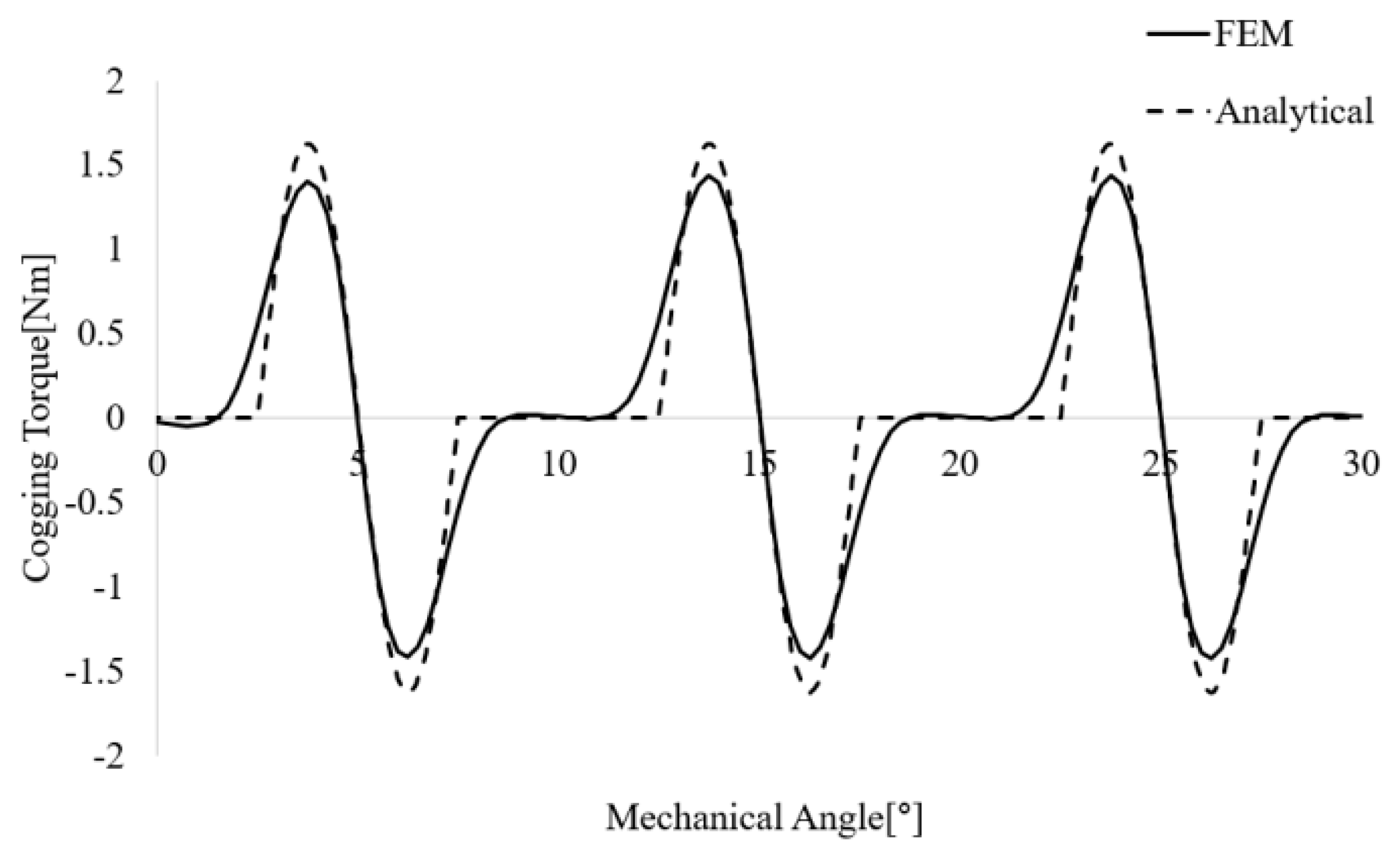
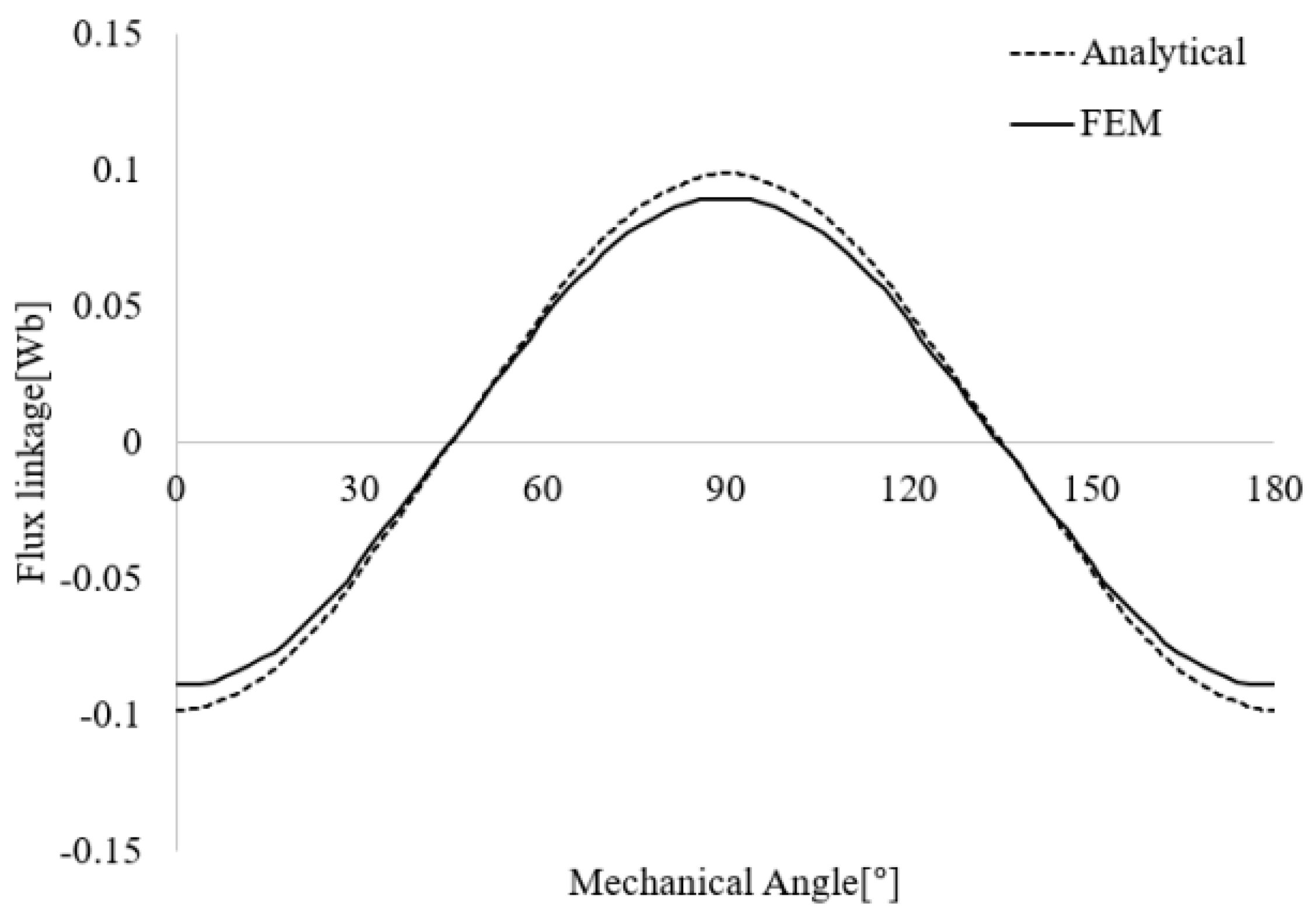
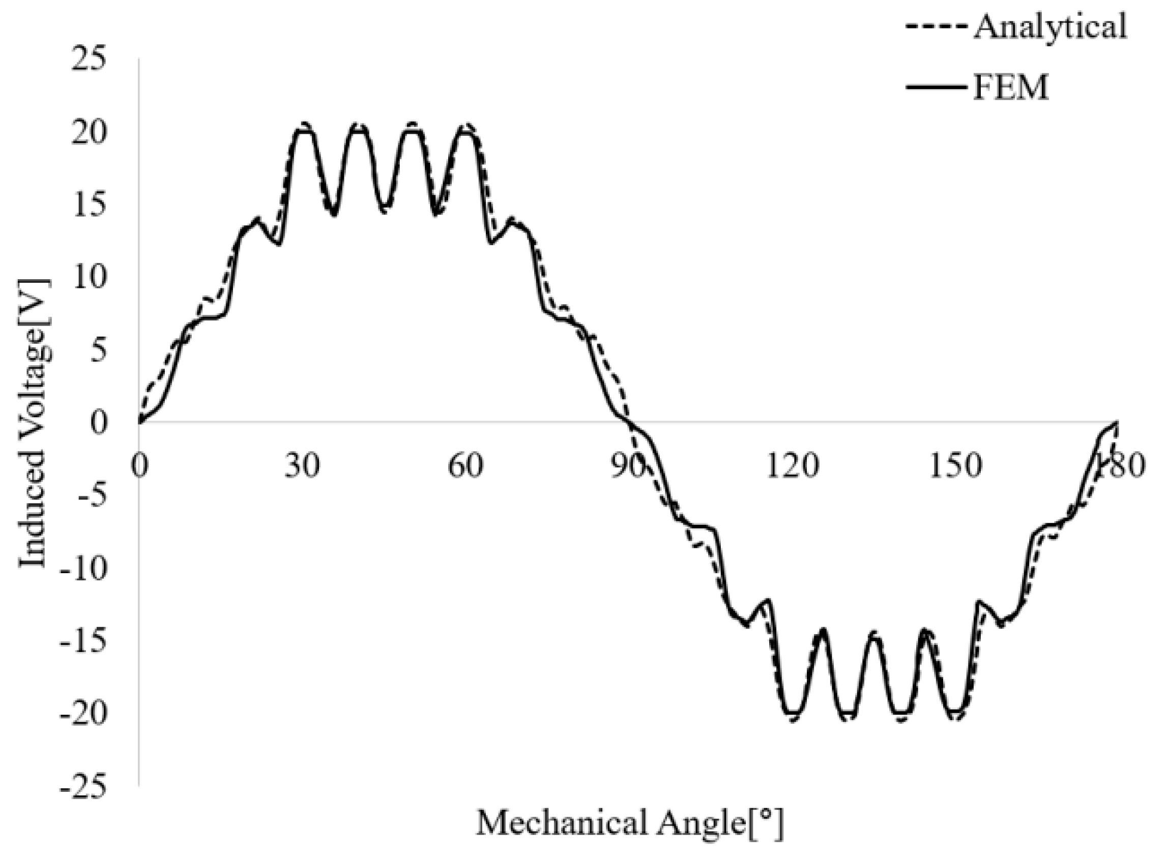
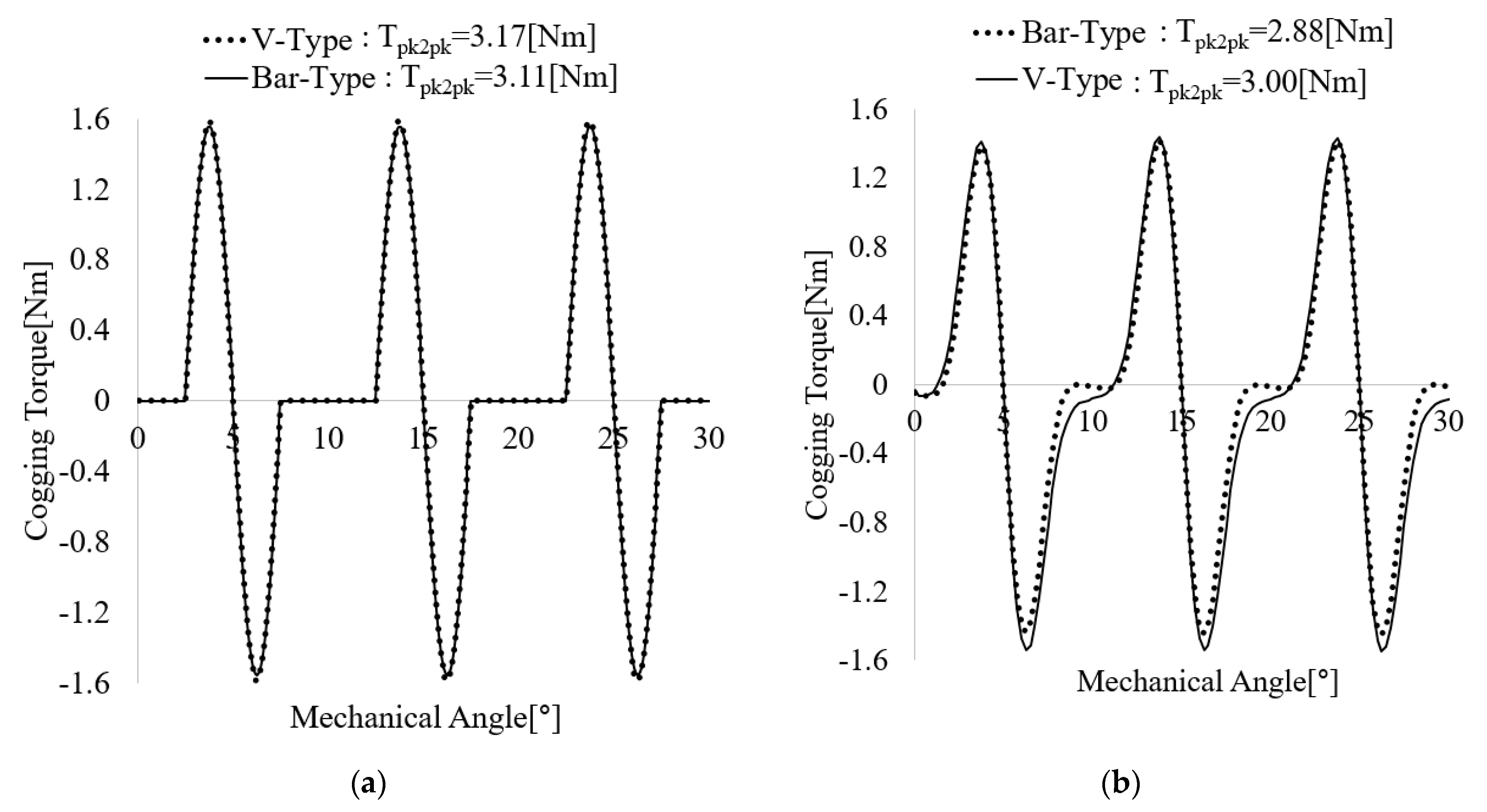
2.3. Calculation Process of Flux Linkage, No-Load-Induced Voltage, and Cogging Torque

Figure 9 shows the flux linkage derived through the HEMC and the FEM. Equation (25) represents the flux linkage of one coil. In the case of this model, the number of slots per phase per pole is three. Therefore, the flux linkage in one phase can be obtained as in Equation (26). By differentiating Equation (26), the no-load-induced voltage can be derived as Equation (27). Figure 10 shows a comparison of the no-load-induced voltage derived from the HMEC and the FEM. The cogging torque (Equation (29)) is derived by differentiating the air gap energy of Equation (28). Figure 11 shows a comparison of the cogging torque waveform derived from the HMEC and FEM.
λ c o i l ( α ) = N c o i l r s i L s t k 0 π N p B g t n ( θ , α ) G s ln ( θ ) d θ
λ p h ( θ , α ) = λ c o i l 1 ( θ θ s p , α ) + λ c o i l 2 ( θ , α ) + λ c o i l 3 ( θ + θ s p , α )
E p h = d λ p h ( α ) d α
W ( α ) g = 0 L s t k r r o r s i 0 2 π B g n 2 ( θ , α ) G s ln 2 ( θ ) d θ
T c o g ( α ) = d W ( α ) d α = d d α ( L s t k 4 μ 0 ) ( r s i 2 r r o 2 ) 0 2 π B g n 2 ( θ , α ) G s ln 2 ( θ ) d θ
where N c o i l , L s t k , λ c o i l and λ p h are the turns of one coil, stack length, flux linkage of one coil, and flux linkage of one phase.

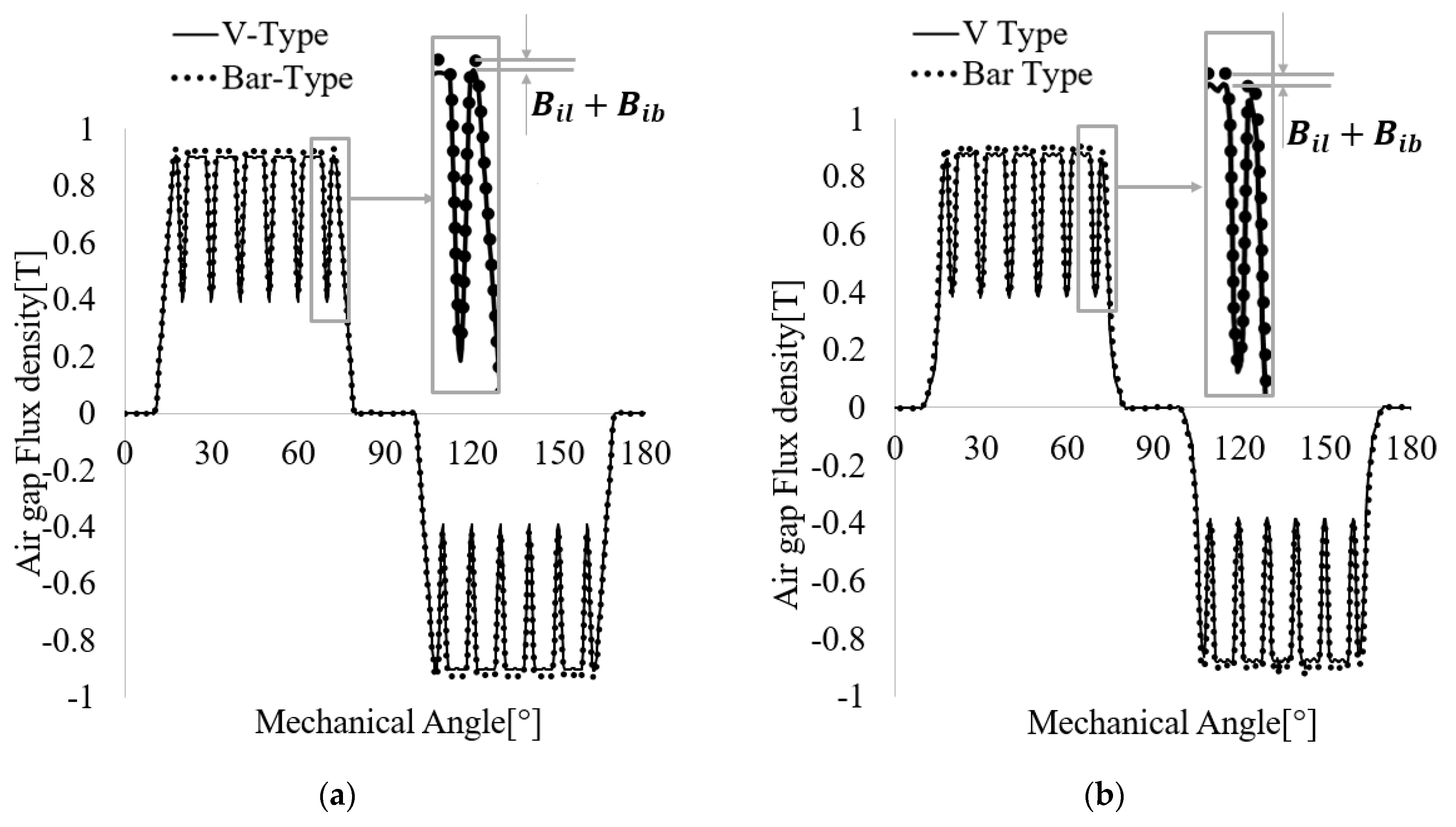
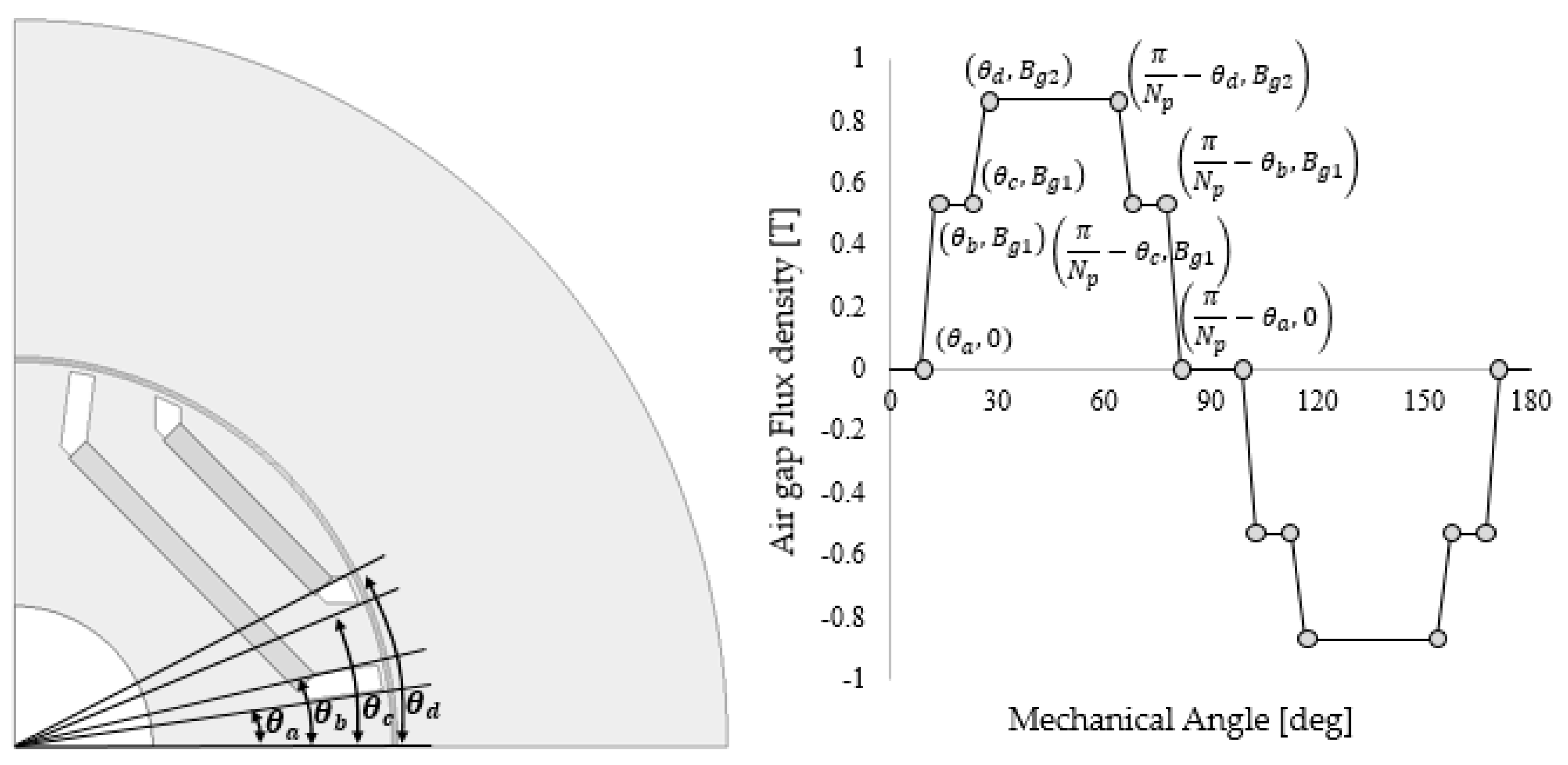
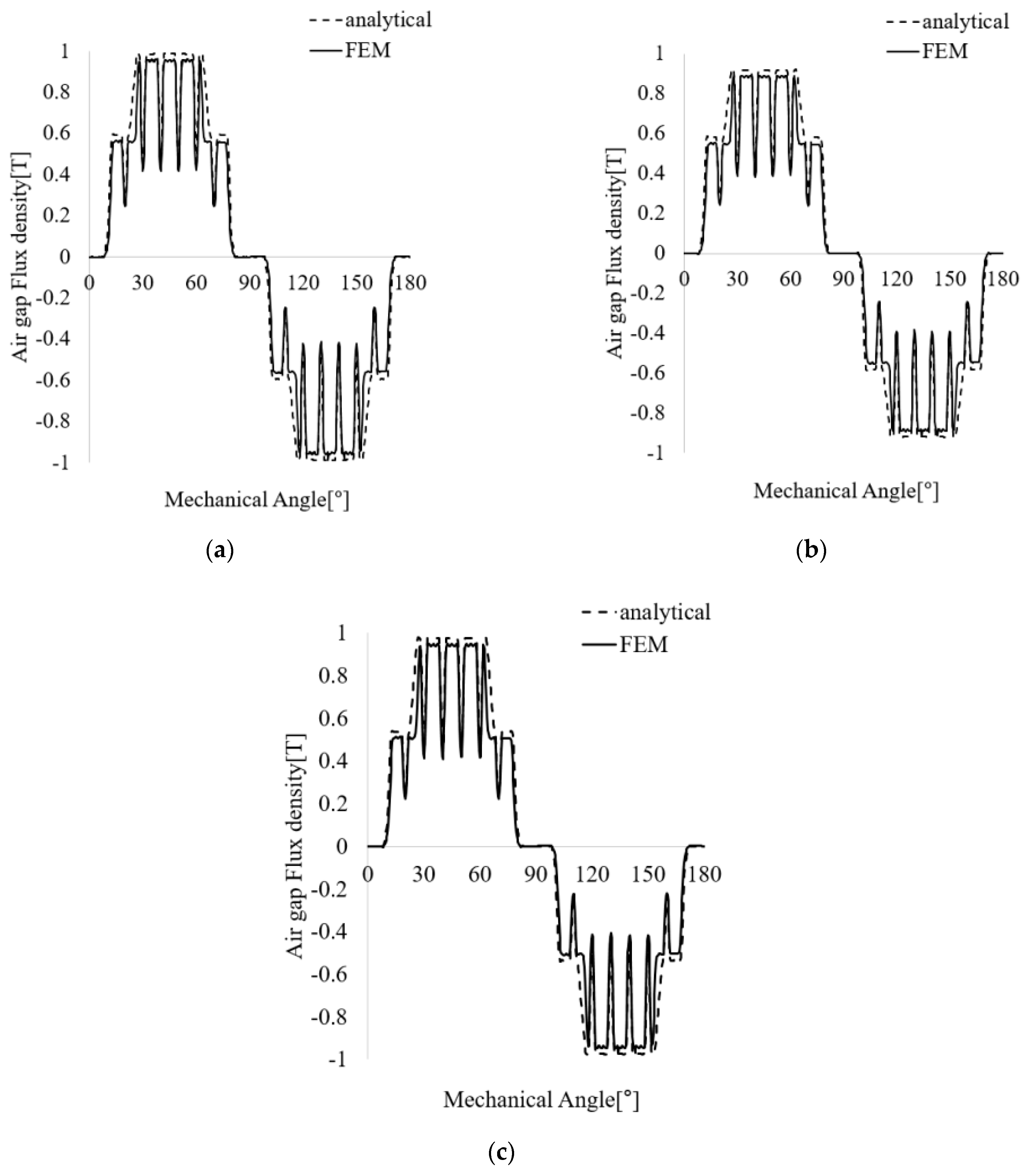
3. Proposed Calculation Method of Air Gap Flux Density Distribution

3.1. Calculation of Air Gap Flux Density Distribution by Permanent Magnet V-Type Rotor

Figure 12 shows a magnetic equivalent circuit of a V-type rotor. As shown in Figure 12, unlike the bar shape, the V shape has an inner bridge and barrier part on the central axis of the pole arc. In addition, by adjusting the angle of the magnet, the area of the permanent magnet can be increased compared with the bar shape. Figure 13 shows a comparison of flux density distribution of the air gap with a bar-type and a V-type rotor with slots. Because the area of the air gap and the permanent magnet is the same, as shown in Figure 13, the difference of the two rotors is the difference in leakage flux according to the presence or absence of the inner bridge and barrier. Therefore, if the area of the permanent magnet is not increased in the V shape, the flux per pole drops as shown in Equations (30) and (31) because of the inner leakage flux. In addition, as shown in Equation (32), as the leakage of the bridge and barrier change, the value decreases and the cogging torque changes, as shown in Figure 14. Figure 14 shows a comparison of cogging torque for a bar-type and a V-type rotor with slots. Table 1 shows comparison of magnetic field distribution parameters of bar-type and V-type rotor when there is a slot.
K l t o t a l = 2 R m | | R i l | | R o l 2 R m
ϕ g = 1 2 K r R g 1 2 K r R g + 1 2 R i b + 1 R o b + 1 2 K l t o t a l R m ϕ r
G min = 1 g + 2 C t K r μ 0 A g ( 1 2 R i b + 1 R o b + 1 2 K l t o t a l R m ) 1 g + 2 C t K r μ 0 A g ( 1 2 R i b + 1 R o b + 1 2 K l t o t a l R m ) ( 1 + π r s i θ s o 4 g )
where R i l , R o l , R i b and R o b are reluctance of the inner and outer barrier, and inner and outer bridge.

3.2. Calculation of Flux Density Distribution of the Air Gap by Permanent Magnet Double-Layer Type Rotor

Figure 15 shows the air gap flux density distribution of a slotless double-layer bar-type rotor. In the double-layer bar-type rotor, the air gap region corresponding to the permanent magnet should be divided into two parts.
B g ( θ ) = { 0 0 θ < θ a B g 1 ( θ b θ a ) ( θ θ a ) θ a θ < θ b B g 1 θ b θ < θ c B g 1 ( θ d θ c ) ( θ θ c ) θ c θ < θ d B g 2 θ d θ < π N p θ d B g 2 ( θ d θ c ) ( θ ( π N p θ c ) ) π N p θ d θ < π N p θ c B g 1 π N p θ c θ < π N p θ b B g 1 ( θ b θ a ) ( θ ( π N p θ a ) ) π N p θ b θ < π N p θ a 0 π N p θ a θ < π N p
B g n = 4 B g 1 π N p ( θ b θ a ) ( 2 n 1 ) 2 ( sin N p θ b ( 2 n 1 ) sin N p θ a ( 2 n 1 ) ) + 4 ( B g 2 B g 1 ) π N p ( θ d θ c ) ( 2 n 1 ) 2 ( sin N p θ d ( 2 n 1 ) sin N p θ c ( 2 n 1 ) )
Equation (33) shows the magnetic flux density distribution by permanent magnet. Applying this expression to the Fourier series yields Equation (34). Although the flux per pole drops when the same permanent magnet is used, the harmonic order is reduced because the air gap flux density can be made closer to sinusoidal. The double-layer rotor can be classified into three types. As shown in Figure 15, one is a double-layer bar (DB) structure, the second is a double-layer V (DV) structure, and the last is a delta (mixed bar and V-type) structure. The number of permanent magnets used, area of the air gap, and area of the permanent magnet are the same. Therefore, the amount of flux per pole in the two regions varies depending on the presence of the inner barrier and bridge. By applying these conditions, the flux density of the air gap for each two-layer shape in Table 2 was calculated.
Figure 16 shows the magnetic equivalent circuit of a permanent magnet when there is no slot for each two-layer rotor. Table 2 shows equations of parameters of air gap flux density distribution according to double-layer rotor type. Because the reluctance of the rotor and stator core were ignored and there was an effective area difference of the air gap between the HMEC and FEM, the value calculated by the HMEC had an error ranging from 2.54% to 3.53% compared with that of the FEM, as shown in Table 3, which shows a comparison of the magnetic field distribution parameters of double layer rotors when there is a slot. In addition, the flux density of the air gap in the DB without the inner bridge and barrier was the highest, and that of the DV was the lowest. The delta shape had a medium flux per pole, but there was no barrier or bridge in the two-layer part, so the inner magnetic flux was large, and the outer magnetic flux was rather small compared with those of the double-layered V-shape. The comparison of flux density distribution when there is a slot for each two-layer shape derived through the HMEC and FEM is represented in Figure 17. As shown in Table 4, it compares the computing time of the HMEC and FEM. The time to calculate the air gap flux densities of B g t 1 , B g t 2 is 0.103622 s for HMEC and 390.0 s for FEM. It represents that computing time of the proposed analysis model is extremely fast.

4. Conclusions

In this paper, a hybrid magnetic equivalent circuit method combined with Carter’s coefficient is proposed. It is a design method that combines the spatial harmonic method and the magnetic circuit method. The magnetic field distribution according to the rotor type was derived through the hybrid magnetic equivalent circuit method, and the cogging torque and no-load counter electromotive force were derived through the magnetic field distribution map. Through the hybrid magnetic equivalent circuit method, the existing design method was enhanced with reduced analysis time and intuitive design parameters. However, an error occurred because of the difference in the effective air gap area, as a result of ignoring the iron core resistance of the rotor and stator and the effect of bridge magnetic saturation. However, because this error was less than 5% in error range compared with the FEM, the proposed hybrid magnetic equivalent circuit method is considered valid.

Author Contributions

Conceptualization, I.-S.S.; Data curation, I.-S.S. and B.-W.J.; Formal analysis, I.-S.S.; Investigation, B.-W.J.; Supervision, K.-C.K.; Writing—original draft, B.-W.J.; Writing—review& editing, K.-C.K. All authors have read and agreed to the published version of the manuscript.

Funding

This work was supported by the Technology Innovation Program (20011435, development of large capacity Etransaxle and application technology of 240 kW class in integrated rear axle for medium and large commercial vehicles) funded by the Ministry of Trade, Industry and Energy (MOTIE, Korea). This work was supported by the Korea Institute of Energy Technology Evaluation and Planning (KETEP) and the Ministry of Trade, Industry and Energy (MOTIE) of the Republic of Korea (No. 20204030200080).

Conflicts of Interest

The authors declare no conflict of interest.

References

  1. Chen, L.; Hopkinson, D.; Wang, J.; Cockburn, A.; Sparkes, M.; O’Neill, W. Reduced Dysprosium Permanent Magnets and Their Application in Electric Vehicle Traction Motors. IEEE Trans. Magn. 2015, 51, 8109004. [Google Scholar] [CrossRef]
  2. Kim, M.J.; Cho, S.Y.; Lee, K.D.; Lee, J.J.; Han, J.H.; Jeong, T.C.; Kim, W.-H.; Koo, D.-H.; Lee, J. Torque Density Elevation in Concentrated Winding Interior PM Synchronous Motor With Minimized Magnet Volume. IEEE Trans. Magn. 2013, 49, 3334–3337. [Google Scholar] [CrossRef]
  3. Akaki, R.; Takahashi, Y.; Fujiwara, K.; Matsushita, M.; Takahashi, N.; Morita, M. Effect of Magnetic Property in Bridge Area of IPM Motors on Torque Characteristics. IEEE Trans. Magn. 2013, 49, 2335–2338. [Google Scholar] [CrossRef]
  4. Jung, H.-C.; Park, G.-J.; Kim, D.-J.; Jung, S.-Y. Optimal Design and Validation of IPMSM for Maximum Efficiency Distribution Compatible to Energy Consumption Areas of HD-EV, 2016 IEEE Conference on Electromagnetic Field Computation (CEFC). IEEE Trans. Magn. 2017, 53, 8201904. [Google Scholar]
  5. Kang, G.-H.; Son, Y.-D.; Hur, J. A Novel Cogging Reduction Method for Interior-Type Permanent-Magnet Motor. IEEE Trans. Ind. Appl. 2009, 45, 161–167. [Google Scholar] [CrossRef]
  6. Hur, J.; Reu, J.-W.; Kim, B.-W.; Kang, G.-H. Vibration Reduction of IPM-Type BLDC Motor Using Negative Thrid Harmonic Elimination Method of Air-Gap Flux Density. IEEE Trans. Ind. Appl. 2011, 47, 1300–1309. [Google Scholar]
  7. Yu, H.-C.; Yu, B.-S.; Yu, J.-T.; Lin, C.-K. A Dual Notched Design of Radial-Flux Permanent Magnet Motors with Low Cogging Torque and Rare Earth Material. IEEE Trans. Magn. 2014, 50, 8203104. [Google Scholar] [CrossRef]
  8. Bonthu, S.S.R.; Bin Tarek, T.; Choi, S. Optimal Torque Ripple Reduction Technique for Outer Rotor Permanent Magnet Synchronous Reluctance Motors. IEEE Trans. Energy Convers. 2018, 33, 1184–1192. [Google Scholar] [CrossRef]
  9. Mun, J.-M.; Park, G.-J.; Seo, S.-H.; Kim, D.-W.; Kim, Y.-J.; Jung, S.-Y. Design Characteristics of IPMSM with Wide Constant Power Speed Range For EV Traction. IEEE Trans. Magn. 2017, 53, 8105104. [Google Scholar] [CrossRef]
  10. Kim, W.-H.; Kim, K.-S.; Kim, S.-J.; Kang, D.-W.; Go, S.-C.; Chun, Y.-D.; Lee, J. Optimal PM Design of PMA-SynRM for Wide Constant-Power Operation and Torque Ripple Reduction. IEEE Trans. Magn. 2009, 45, 4660–4663. [Google Scholar] [CrossRef]
  11. Kim, K.-C. A Novel Calculation Method on the Current Information of Vector Inverter for Interior Permanent Magnet Synchronous Motor for Electric Vehicle. IEEE Trans. Magn. 2014, 50, 829–832. [Google Scholar] [CrossRef]
  12. Ma, C.; Zhang, J.; Wang, J.; Yang, N.; Liu, O.; Zuo, S.; Wu, X.; Wang, P.; Li, J.; Fang, J. Analytical Model of Open-Circuit Air-Gap Field distribution in Interior Permanent Magnet Machines Based on Magnetic Equivalent Circuit Method and Boundary Condistions of Macroscopic Equations. IEEE Trans. Magn. 2021, 57, 8104209. [Google Scholar] [CrossRef]
  13. Chen, Y.; Zhu, Z.Q.; Howe, D. 3-D lumped parameter magnetic circuit analysis of single-phase flux-switching permanent magnet motor. IEEE Trans. Magn. Ind. Appl. 2008, 44, 1701–1710. [Google Scholar] [CrossRef]
  14. Wang, J.; Lieu, D.; Lorimer, W.; Hartman, A. Comparison of lumped parameter and finite element magnetic modeling in a brushless DC motor. IEEE Trans. Magn. 1997, 33, 4092–4094. [Google Scholar] [CrossRef]
  15. Sheikh-Ghalavand, B.; Vaez-Zadeh, S.; Isfahani, A.H. An Improved Magnetic Equivalent Circuit Model for Iron-Core Linear Permanent-Magnet Synchronous Motors. IEEE Trans. Magn. 2009, 46, 112–120. [Google Scholar] [CrossRef]
  16. Moallem, M.; Dawson, G.E. An improved magnetic equivalent circuit method for predicting the characteristics of highly saturated electromagnetic devices. IEEE Trans. Magn. 1998, 34, 3632–3635. [Google Scholar] [CrossRef]
  17. Mi, C.; Filippa, M.; Liu, W.; Ma, R.Q. Analytical method for predicting the air-gap flux of interior-type permanent-magnet machines. IEEE Trans. Magn. 2004, 40, 50–58. [Google Scholar] [CrossRef]
  18. Chen, H.; Li, D.; Qu, R.; Zhu, Z.; Li, J. An Improved Analytical Model for Inductance Calculation of Interior Permanent Magnet Machines. IEEE Trans. Magn. 2014, 50, 7027108. [Google Scholar]
  19. Hwang, C.-C.; Cho, Y.H. Effects of Leakage Flux on Magnetic Fields of Interior Permanent Magnet Synchronous Motors. IEEE Trans. Magn. 2001, 37, 3021–3024. [Google Scholar] [CrossRef]
  20. Rahaman, M.A.; Slemon, G.R. Analytical models for interior-type permanent magnet synchronous motors. IEEE Trans. Magn. 1985, 21, 1741–1743. [Google Scholar] [CrossRef]
  21. Radun, A.V. Development of Dynamic Magnetic Circuit Models Including Iron Saturation and Losses. IEEE Trans. Magn. 2013, 50, 7027010. [Google Scholar] [CrossRef]
  22. Liu, G.; Liu, L.; Chen, Q.; Zhao, W. Torque Calculation of Five-Phase Interior Permanent Magnet Machine Using Improved Analytical Method. IEEE Trans. Energy Convers. 2019, 34, 1023–1032. [Google Scholar] [CrossRef]
  23. Zhu, L.; Jiang, S.Z.; Zhu, Z.Q.; Chan, C.C. Analytical Modeling of Multi-segment and Multilayer Interior Permanet Magnet Machines. In Proceedings of the 17th International Conference on Electrical Machines and Systems (ICEMS), Hangzhou, China, 22–25 October 2014; pp. 28–33. [Google Scholar]
  24. Hanselman, D. Brushless Motors: Magnetic Design, Performance, and Control; E-Man Press LLC: Ballston Spa, NY, USA, 2012; p. 656. [Google Scholar]
  25. Hendershot, J.R.; Miller, T.J.E. Design of Brushless Permanent-Magnet Machines; Motor Design Books LLC: Venice, FL, USA, 2015; p. 798. [Google Scholar]
Figure 1. Three regions of the slotless flux line distribution by permanent magnet.
Energies 14 05011 g001
Figure 2. The slotless air gap flux density distribution.
Energies 14 05011 g002
Figure 3. Magnetic circuit of a slotless permanent magnet.
Energies 14 05011 g003
Figure 4. Flux line distribution by permanent magnets with slots.
Energies 14 05011 g004
Figure 5. Magnetic equivalent circuit of a permanent magnet with slots.
Energies 14 05011 g005
Figure 6. Air gap flux line distribution per slot when there are slots.
Energies 14 05011 g006
Figure 7. Magnetic field distribution: (a) flux density of the teeth and shoe, and (b) slot factor.
Energies 14 05011 g007
Figure 8. Comparison of the air gap flux density distribution by permanent magnet with slots derived from the HMEC and FEM.
Energies 14 05011 g008
Figure 9. Comparison of the flux linkage derived from the HMEC and FEM.
Energies 14 05011 g009
Figure 10. Comparison of the no-load-induced voltage derived from the HMEC and the FEM.
Energies 14 05011 g010
Figure 11. Comparison of the cogging torque derived from the HMEC and the FEM.
Energies 14 05011 g011
Figure 12. Magnetic equivalent circuit of a V-type rotor.
Energies 14 05011 g012
Figure 13. Comparison of flux density distribution of the air gap with bar-type and V-type rotors with slots: (a) HMEC, (b) FEM.
Energies 14 05011 g013
Figure 14. Comparison of cogging torque with bar-type and V-type rotors with slots: (a) HMEC, (b) FEM.
Energies 14 05011 g014
Figure 15. Air gap flux density distribution of a slotless double-layer bar rotor.
Energies 14 05011 g015
Figure 16. Magnetic equivalent circuit of a permanent magnet when there is no slot for each two-layer rotor: (a) DB, (b) DV, and (c) delta.
Energies 14 05011 g016aEnergies 14 05011 g016b
Figure 17. Comparison of flux density distribution when there is a slot for each two-layer shape derived through the HMEC and FEM: (a) DB, (b) DV, and (c) delta.
Energies 14 05011 g017
Table 1. Comparison of magnetic field distribution parameters of bar-type and V-type rotor when there is a slot.
TypeBarVUnit
K l t o t a l 0.98980.9891[-]
R b t o t a l 1,051,237831,420[AT/Wb]
R g t t o t a l 922904.22[mT]
G min 0.4470.438[-]
Table 2. Equations of air gap flux density distribution parameters according to double-layer rotor type.
Equation
Air Gap Flux ϕ g 1 2 = ϕ g 11 2 ϕ g 12 2 ϕ g 2 2 = ϕ g 12 2 + ϕ g 22 2
Air Gap Flux Density B g 1 = ϕ g 1 A g 1 B g 2 = ϕ g 2 A g 2
Slot Factor G ( θ ) = B g 1 ( θ ) + B g 2 ( θ ) B g 1 + B g 2
DB ϕ g 11 2 = P g 1 P m 1 + P o b 1 + P g 1 + P A ϕ r 1 2 ϕ g 21 2 = P A P m 1 + P o b 1 + P g 1 + P A ϕ r 1 2 ϕ g 12 2 = P g 1 P m 1 + P o b 1 + P g 1 + P A P B P m 2 + P o b 2 + P B ϕ r 2 2 ϕ g 22 2 = P B P m 2 + P o b 2 + P B ϕ r 2 2 P A = 2 K l 2 R m 2 | | R o b 2 + 2 R g 2 P B = 2 K l 2 R m 1 | | R o b 1 | | 2 R g 1 + 2 R g 2
DV ϕ g 11 2 = P g 1 P m 1 + P o b 1 + P i b 1 + P g 1 + P A ϕ r 1 2 ϕ g 21 2 = P A P m 1 + P o b 1 + P i b 1 + P g 1 + P A ϕ r 1 2 ϕ g 12 2 = P g 1 P m 1 + P o b 1 + P i b 1 + P g 1 P B P m 2 + P o b 2 + P B ϕ r 2 2 ϕ g 22 2 = P B P m 2 + P o b + P i b + P B ϕ r 2 2 P A = 2 K l 2 R m 2 | | R o b 2 | | R i b 2 + 2 R g 2 P B = 2 K l 1 R m 1 | | R o b 1 | | R i b 1 | | 2 R g 1 + 2 R g 2
Delta ϕ g 11 2 = P g 1 P m 1 + P o b 1 + P i b 1 + P g 1 + P A ϕ r 1 2 ϕ g 21 2 = P A P m 1 + P o b 1 + P i b 1 + P g 1 + P A ϕ r 1 2 ϕ g 12 2 = P g 1 P m 1 + P o b 1 + P i b 1 + P g 1 P B P m 2 + P o b + P D ϕ r 2 2 ϕ g 22 2 = P B P m 2 + P o b + P B ϕ r 2 2 P A = 2 K l 2 R m 2 | | R o b 2 + 2 R g 2 P B = 2 K l 1 R m 1 | | R o b 1 | | 2 R g 1 + 2 R g 2
Table 3. Comparison of parameter calculations of the air gap flux density distribution according to double-layer rotor type.
HMECFEM
TypeDBDVDeltaDBDVDeltaUnit
Ct11.16 [-]
Ct21.17
Gmin0.4540.4450.4430.4360.4360.437
Bgt1594582536562545508[mT]
Bgt2987918975960890947
Table 4. Comparison of calculation time about air gap flux density distribution.
HMECFEM
TypeDBDVDeltaDBDVDeltaUnit
Calculating Time (Bgt1, Bgt2)0.103622389.00[sec]
Publisher’s Note: MDPI stays neutral with regard to jurisdictional claims in published maps and institutional affiliations.

