Review

The Review of Carbon Capture-Storage Technologies and Developing Fuel Cells for Enhancing Utilization

1
Department of Chemical Engineering, Rajiv Gandhi Institute of Petroleum Technology, Jais 229304, India
2
Department of Petroleum Engineering, Rajiv Gandhi Institute of Petroleum Technology, Jais 229304, India
*
Authors to whom correspondence should be addressed.
Equal Contribution.
Energies 2021, 14(16), 4978; https://doi.org/10.3390/en14164978
Submission received: 23 June 2021 / Revised: 3 August 2021 / Accepted: 5 August 2021 / Published: 13 August 2021

Abstract

:
The amount of CO2 released in the atmosphere has been at a continuous surge in the last decade, and in order to protect the environment from global warming, it is necessary to employ techniques like carbon capture. Developing technologies like Carbon Capture Utilization and Storage aims at mitigating the CO2 content from the air we breathe and has garnered immense research attention. In this review, the authors have aimed to discuss the various technologies that are being used to capture the CO2 from the atmosphere, store it and further utilize it. For utilization, researchers have developed alternatives to make profits from CO2 by converting it into an asset. The development of newer fuel cells that consume CO2 in exchange for electrical power to drive the industries and produce valuable hydrocarbons in the form of fuel has paved the path for more research in the field of carbon utilization. The primary focus on the article is to inspect the environmental and economic feasibility of novel technologies such as fuel cells, different electrochemical processes, and the integration of artificial intelligence and data science in them, which are designed for mitigating the percentage of CO2 in the air.

1. Introduction

It is a pretty common fact that carbon dioxide is one of those components of air that is responsible for the growing global warming and greenhouse gas emissions [1]. The majority of the total carbon dioxide emissions in the world is owed to industries, while the remnant can be attributed to emissions from vehicles and other similar sources [2]. To improve the health of nature, it is necessary to mitigate the amount of these harmful gases from the environment, and for this, it is necessary that the great minds in energy sciences muster together and develop technologies to achieve the aim of a cleaner environment. With the rise of industries, the amount of CO2 emitted each year has been increasing at an alarming rate and to achieve zero carbon emissions, the removal of CO2 becomes extremely important [3]. Many technologies capture and store CO2 in an attempt to isolate it from the atmosphere and prevent any further harm. However, these technologies are under development and have the problems of low efficiency, energy loss, etc. Therefore, development was focused on technologies offering higher efficacy in lowering the CO2 emissions, like fuel cells [4,5,6]. In subsequent sections, the evolution of a fuel cell and how it helps in mitigating CO2 levels in the environment will be discussed.
Carbon-capture and storage is a breakthrough technology that has been developed to reduce the CO2 content from the air and store it in such a way that it is never emitted into the environment. This technology is much more commonly used in the oil and gas industry because processes like CO2-based enhanced oil recovery have been in use for decades for enhancing the efficiency of oil recovery from the reservoirs [7,8]. In this paper, the different storage mechanisms that can be used to captivate the captured CO2 from the atmosphere such as geological sequestrations, storage in oceans, storage using metal–organic frameworks (MOFs) [9,10], etc., as well as the different processes that are used to capture the CO2 in the first place, have been discussed. The amount of CO2 captured on an annual basis is extremely high, and so to store it, there is an essential requirement of space. Therefore, storing underneath the ground is considered a promising mode of storage, since the available space is sufficient to store all of the CO2 captured.
However, there are risks of leakage associated with this mode of storage, and hence a large number of people are employed for analyzing this method and finding newer solutions to mitigate these risks [11,12,13,14,15]. A discussion on the detailed ways of governing underground storage has been provided. In many cases, it is preferred to use the captured CO2 in entities like syngas, methanol, and other chemical compounds through various methods like electrochemically or biochemically converting the stored CO2 for further usage. The article also mentions in brief about the commercial ventures that are being carried out to store as well as to convert the CO2 into valuables, and these methods are called carbon capture and utilization technologies. Simply storing CO2 at one place forever is an added burden to the businessmen, as extra costs are incurred and no monetary profit is made, but when methods like electrochemical conversion of CO2 using fuel cells, CO2-based enhanced oil recovery, etc., are pursued, they help in making profits as well.
Utilization technologies would be more prominent in the future owing to the massive developments in technologies. Electrochemical fuel cells have been built that produce fuel from CO2 as well as produce electricity [16,17]. Therefore, it is extremely likely that coal-based electricity production, which causes an increment in CO2 emission, would be replaced by the electrochemical cells. Electrochemical fuel cell demand ought to surge owing to advancements of systems such as solid oxide co-electrolyzer (SOCE) and carbon formation reactor (CFR) cells. These cells have been discussed in the succeeding sections. Since there are many commercial projects using CO2, transportation of CO2 becomes important, primarily occuring through pipelines and ship-based transformations.
The growing need for CO2 can be understood by the fact that there are as many as 6500 km [18] of pipelines across the whole world specifically for the transport of CO2. In this paper, there is a detailed discussion about the processes used in transportation as well as the risks associated with them. The articles also mention some measures that are usually taken to prevent problems like leakages or blockages, etc. Upon in-depth research, carbon capture and storage has been made an extremely technically feasible technology, but from an economic point of view, the feasibility has not been established. However, the increasing interest of the major economies of the world in technology like carbon-capture-utilization-storage (CCUS) is a positive sign indicating that the world would be able to achieve economic feasibility as well.

2. Role of CCS

The key driver of economic development is innovation in information resources that increase productivity. It is expected that fast-growing countries will begin to narrow the per capita income disparity with developing nations and will start to push towards equilibrium with the industrialized world through the next century. The technological reliability and cost output of current energy technologies are projected to continue to develop over time. This would increase the CO2 emissions and the potential incorporation of such technologies into the production of modern fossil-fueled power is predicted to dramatically reduce the costs incurred in the capture of CO2.
It has been predicted that the performance of carbon capture will increase with time, i.e., modern and advanced technology and methods may come forward to reduce the energy penalty involved in capturing carbon from the waste streams. Detailed explanations of carbon capture and sequestration technologies have been published [19,20,21]. Conceptually, they are similar to strategies used to reduce the emissions of SO2, NOx, particulate matter, and other pollutants [22,23,24,25,26]. One big distinction, though, is that the volume of CO2 produced is far higher than the other pollutants [27,28]. Now that CO2 can be exported and sequestered efficiently, carbon capture is favored. Capturing and sequestration of carbon is an alternative to reduce the economic risks of aggressive climate change policies, as electricity production and availability remain uncompromising in terms of lowering CO2 emissions. The optimum approach and the associated costs of a specific climate security policy are unpredictable and theoretically significant [29]. Uncertainties emerge from the development and versatility of electricity demand and low-carbon energy production. There is some evidence that macro-economic mitigation costs would escalate significantly if aggressive climate security targets are to be pursued to prevent harmful climate change [30].
Ways to tackle excessive CO2 generation problems from industries:
  • Improvement of energy transfer and usage efficiency;
  • The ratio of CO2 pollution to primary consumption by transitioning to carbon-free electricity technology;
  • Trap and store CO2 at large industrial point sources in geological formations;
  • To accommodate alternative sources of fuel, which include a cleaner production process without carbon emissions.
To evaluate these choices and the related complexities, different integrated evaluation models can be used. A few integrated evaluation models used to tackle carbon capture and sequestration are:
The Model MIND (the Model of Investment and Technological Development):
  • Energy demand may be minimized either by replacing it with capital and labor in a macro-economic output mechanism or by growing energy efficiency in an endogenous way. Investments in conventional and clean energy markets decide the carbon balance. The performance of production in renewables improves by learning. Alternatively, fossil dioxide may be collected and deposited in natural structures that are susceptible to leakage. Utility per capita depends on per capita consumption with declining returns.
  • MiniCAMmodel, version MiniCAM 98.3 [31,32,33] is an applied environmental change appraisal platform with an emphasis on agricultural systems, carbon cycle components, and global energy [34].
In Figure 1, the CO2 from the atmosphere is shown to be uptaken by a biomass source and processed in a plant. Following this, the captured CO2 is stored using geological sequestration, and the other energy and non-energy products are released as byproducts, which are later utilized in various industrial and non-industrial activities.
Employing aqueous amine scrubbers to use various forms of sorbents, like porous solids or ionic liquids (ILs), is one potential way to address the problems related to CO2 capture. When contrasted to aqueous amine scrubbers, porous materials like silicas, zeolites, porous organic polymers (POPs), metal–organic frameworks (MOFs), and covalent–organic frameworks (COFs) possess greater thermal stabilities and smaller heat capacities [35,36,37,38,39,40]. Similarly, ILs have benefits over aqueous amines like non-volatility and architectural adjustability. Despite the fact that hydrophobic porous materials like silicon-rich zeolites and carbons can scrub CO2 from higher concentration stream (for example, crude biogas) [41], most of these materials are unable to eliminate CO2 from humid lower concentration streams like flue gas emissions [42]. Since CO2 and water compete for that same physisorption site within those sorbents, this restriction occurs. Another issue needed to be considered with porous solid adsorbents is their low thermal conductivity, which makes heating and cooling of adsorbent during adsorption and desorption cycling more difficult.
The discovery of novel chemisorptive routes for selective CO2 capture is an underutilized method for overcoming constraints of amine-based materials. The production of carbamic acids by carbon dioxide capture at sites of amine is theoretically advantageous since it raises the (carbon dioxide/amine sorption) ratio to (one:one) [43]. Mounting amines on the ILs anions derived from amino acid favors CO2 capture according to Schneider, Brennecke, and colleagues [44]. When compared to ILs with amine-functionalized cations that work via the conventional mechanism of ammonium carbamate, this modification in mechanism doubled the molar adsorption efficiency of such ILs. By CO2 capture in ILs containing alkoxide or phenoxide anions and organic cations; Li, Dai, and colleagues proved that amines may be entirely bypassed [45]. At 30 °C and 1 atm, Wang and colleagues discovered that an ionic liquid with an aspartate dianion could reversibly bind 1.96 moles carbon dioxide per mole IL. This was thought to happen mostly through two consecutive reactions at a single amine location [46]. Due to their outstanding hydrothermal and oxidative stability, Long and colleagues recognized MOF M2 (dobpdc) (dobpdc4 = 4,4′-dioxidobiphenyl-3,3′-dicarboxylate) variants functionalized with the diamine 2,2-dimethyl-1,3-diaminopropane (dmpn) as favorable adsorbents for the post-combustion CO2 capture [47,48].
Looking to nature for motivation is another possible way to unleash novel selective CO2 capture reactivities in porous materials. Carbonic anhydrase enzymes, for instance, are vital for CO2 transfer in the body of human. The reversible interaction of a Zn–OH species with CO2 to generate Zn–OCO2H is used by several components of these classes. Zhang and colleagues showed in a previous research that high-valent monodentate metal hydroxides in the water-stable MOFs MnIIMnIII(OH)Cl2(bbta) and [CoIICoIII(OH)Cl2(bbta)] (bbta2 = dihydrobenzo[1,2-d:4,5-d′]bis([1,2,3]triazolate) even in humid situations, firmly bind CO2 with excellent CO2:N2 selectivity [25]. In (Zn5(OH)4(btdd)3) (btdd = bis(1,2,3-triazolo[4,5-b],[4′,5′-i])dibenzo[1,4]dioxin), Dincă and colleagues exhibited an analogous bioinspired method to CO2 capture. When contrasted against Zn(ZnOH)4(bibta)3, this structure showed higher CO2 binding, but with a reduced adsorption ability at lower pressures (0.9 milli-mole per gram at temperature of 25 °C and 23 mbar pressure of CO2). This sorbent finding is yet naive, and to develop transformational materials—and sorption processes—for decreasing anthropogenic CO2 emissions, a novel era of computational, analytical, and synthetic chemistry is required.

2.1. Technological Aspects

The CO2 reduction may be incorporated into the power production cycle at various points of the power plant cycle. It can be placed either at the ends of a pipe to clean the flue gas or even at the starting point, by extracting CO2 from the fuel before the actual combustion phase. Technologies are accessible commercially for completing any of these steps, and the main obstacle for advancing the idea is to incorporate these technologies into large-scale implementation programs [49]. A variety of separation methods are currently being explored, of which the most successful solutions are the following [50]:

2.1.1. Post Combustion Capture and Pre Combustion Capture

Post-combustion capture implies isolating the CO2 from the flue gas. In a power plant when fossil fuel is burnt with air, flue gases escape the plant through the stack, which is at ambient pressure. CO2 is then collected, ideally by a process of chemical absorption [51,52,53,54,55,56]. Its usage today includes the cleaning of NOx and SO2 before the isolation of CO2. If the carbon sinks accept NOx and SO2, independent management measures and the sequestration of NOx and SO2 along with CO2 may be avoided, thereby culminating in a zero-emission power plant. To trap CO2, its concentration should be high else energy expensive, and costly CO2 capture processes will be needed. To do so, oxygen may be incorporated in hydrogen pre-combustion or the oxygen chamber post-combustion.
The process where CO2 is produced alongside a combustible that is free from carbon, such as hydrogen, by burning a fuel is called pre-combustion capture. This process is extremely relevant to various industries, but is most relevantly used in plants generating electric power from the integrated gasification combined cycle (IGCC) where the gasification of the fuel (solid) is done and as a result, so-called synthesis gas is produced that is composed primarily of carbon monoxide (CO) and hydrogen (H2). The carbon dioxide (CO2) gas enters the gasifier at high pressure and is consumed by the physical processes happening. When pre-combustion recovery was studied, it was found that gasoline transforms into CO2 very rapidly. Alongside the formation of CO2, the formation of a fuel that is free from any carbonaceous matter also takes place. The CO2 is then separated from hydrogen [57,58,59,60,61].
Pre-combustion capture entails combining a fuel with oxygen, and steam to produce a synthesis gas or fuel gas that is mostly comprised of CO and H2. In a catalytic reactor known as a shift converter, CO reacts with steam to produce carbon dioxide and additional H2 carbon dioxide is subsequently separated, generally by a physical/chemical absorption, to produce a H2-rich fuel components of pre-combustion CO2 capture, with an emphasis on initiatives wherein collected CO2 is kept or utilized for enhanced oil recovery.
There are two major ways to make syngas; first is adding steam (shown as reaction 1) to the primary fuel, which is known as “steam reforming”, or secondly, adding O2 (shown as reaction 2) to the primary fuel. When it comes to liquid and gaseous fuels, the process is known as “partial oxidation”, and when it comes to solid fuels, it is known as “gasification”, but the fundamentals are the same.
Steamforming   C x H Y + x H 2 O ˙   x C O + ( x + y 2 ) H 2 Δ H C H 4 = 206   KJ   mol 1
Partialoxidation   C x H Y + x / 2 O 2 O ˙   x C O + ( y / 2 ) H 2 Δ H C H 4 = 36   KJ   mol 1
Normally, partial oxidation is carried out with O2 that has been isolated from the air. The method is called auto-thermal reforming when both steam and oxygen are utilized, because the reactions of endothermic reforming are compensated by the reactions of exothermal partial oxidation. Following the syngas generation, the water–gas shift (WGS) reaction is being used for converting carbon monoxide to carbon dioxide and hydrogen by adding steam (shown in reaction (3)):
Water Gas   Shift   C O + H 2 O     C O 2 + H 2 Δ H = 41   Kmol 1
CO2 separation is done at room temperature utilizing traditional washing methods. For power production, the H2-rich gas is utilized as a lower-C fuel in a combined cycle unit (that is, Brayton + Rankine cycle).
The CO2 removal is facilitated by the higher pressure of the water–gas shift product gas stream. CO2 concentrations at the intake of the CO2/H2 separation process can vary from 15 to 60 percent (on dry basis) at a total pressure of 2 to 7 megapascal, making the separation of carbon dioxide and compression process lower energy consuming than post-combustion operations with lower total pressures and CO2 concentrations [62,63]. The CO2 that has been separated is then ready to be stored. However, energy needs for air separation, reforming or gasification, and loss in energy recovery during syngas temperature fluctuations balance out this decreased energy demand.
Pressure swing adsorption methods (PSA) were also used to purify hydrogen by removing CO2, with the goal of achieving higher hydrogen purity and production. Nevertheless, high purity and yield for the heavier carbon dioxide component are required for CCS purposes, requiring a cycle design that differs considerably from standard H2-PSA [64,65,66]. Nonetheless, the PSA separating is a trade-off among CO2 purity and recovery. A modelling research by [65] using activated C as sorbent led to plots of pareto, which reflect the best performance points for a specific PSA cycle, restricted at around ninety-five percent CO2 purity and recovery. A 60 to 40 percent hydrogen to carbon dioxide feed may therefore achieve the required 90 percent CO2 capture at 95 percent CO2 purity.

2.1.2. Artificial Intelligence in Carbon Capture

Artificial intelligence is a deep-belief neural network used to aid in combating climate change and is developing as a strong methodology that has recently demonstrated the ability to alter several boundaries of carbon capture. It proposes a novel approach to coordinate carbon and electrical couplings for the effective and ecologically beneficial operation of the upcoming reduced carbon energy systems. Artificial intelligence requires multiple parameters (operating cost, heat, reduction in renewable power, electricity, carbon emission, etc.) to reflect the complex interaction between them. The optimal solution, out of the multiple goals set, is obtained via particle swarm heuristic. According to Chen, when a carbon capture process is made fully accommodating, then the maximum bilateral benefits between renewable power and carbon capture can be obtained. Chen et al. [67] demonstrated an optimal strategy based on artificial intelligence for scheduling renewable power penetration. A reduction of 51% can be achieved in renewable power curtailments with simultaneous capture of 35% of the emitted carbon due to optimal scheduling of surplus renewable power. Rahimi et al. explained how machine learning (ML) implementations have enhanced the carbon capture process in numerous ways, from the molecule to the process level, including both absorption and adsorption-based techniques. ML aids in process improvement by determining the most cost-effective process scheme, which involves selecting a solid adsorbent and creating a process configuration to forecast thermodynamic parameters. Wu et al. used the most influential CO2 production rate factors, such as solvent circulation duty, solvent concentration, CO2 lean loading, and heat duty, to model and analyze data from an amine-based post-combustion CO2 capture method.

3. CO2 Storage

The CO2-capture technologies have been developed to mitigate the harmful environmental effects caused due to the presence of CO2 in large amounts. However, to make sure that the captured CO2 is not readmitted in the environment, there is a necessity to build efficient and safe storage technologies. Technologies like subsurface storage, ocean-based storage, etc., have been developed and are continuously being improved to allow for the storage of CO2 in adequate amounts.

3.1. Studying the Subsurface Storage of CO2 and Related Challenges

The importance of stripping the air of CO2 has been already discussed, along with the fact that there has been great technological progress in this domain. However, simply capturing the carbon-dioxide is not enough; it is an important requirement to store this captured CO2. While there are many modes that have been tested or are under consideration for CO2 storage, one of the best modes is to store this captured gas beneath the ground owing to the teeming underground storage resource availability. Additionally, by a fortunate chance, there are several places where the entrapment of oil and gases can be done, and thus, a considerable amount of workforce is focused on activities related to the storage of CO2 [68,69,70,71]. For it to be termed as an efficient storage site, there are a few geological characteristics that the site of storage should exhibit. For picking the most appropriate location for pursuing the storage activity of CO2, the carbon dioxide’s thermo-physical properties with the reservoir fluids must be analyzed ineffably. This analysis also provides a better insight into designing strategies for injection and also, for making a prediction about the CO2 that has been injected. Since previous researches have contributed a good amount of insight into the thermo-physical properties of CO2, the modern researchers have tried to gather their focus on the effects that the impurities have on the above mentioned thermo-physical properties [72,73]. Apart from analyzing the fluid properties and the geoscience of the reservoir, it is important to evaluate the extent to which it is suitable to have CO2 injection, and this evaluation is termed as site characterization. These evaluation techniques include activities like making an observation from the geological perspective and taking samples.
Therefore, the scopes of research in this domain have expanded from technical feasibility and have moved on to finding answers to provide better characterization, reduced uncertainty, managed risks of leakage, and also to evaluate the role that CO2 capture plays in energy systems. Apart from analyzing the fluid properties and the geoscience of the reservoir, it is important to evaluate the extent to which it is suitable to have CO2 injection, and this evaluation is termed as site characterization. These evaluation techniques include activities like making an observation from the geological perspective and taking samples. However, all these topics are outside the scope of this review, and if interested, the readers should read the vast literature available that discussed the above mentioned facets of CO2 storage.

3.2. The Capacity Available for Storage and the Role Played by CO2 in Different Energy Systems

It has been found that the space available for underground storage is enough to meet the environmental targets. The countries with higher CO2 emissions are reported to have spaces in abundance to store all the captured CO2. The storage capacity of a site is dependent on the potential of a subsurface site to store CO2 and evaluating that capacity is a task having paramount importance in reservoir management [74,75]. At a given location, as the injection progresses further, there can be an up-gradation of models so that they can paint a more accurate picture of the storage capacity. There is a huge importance of storing CO2, and its importance is judged by its potential to manage the CO2 emissions. Worldwide assessments have been made on the capacity to store CO2, and these assessments support the fact that the pore volume available for injection exceeds the one available for CO2 mitigation [76,77]. A majority of modeling, highlighting the reports of IPCC, have not considered capacity limiting. In the more recent reports, the capacity estimates are termed as static and they are calculated by considering the assumption that a part of the total pore space of a geologic unit can be used for storage purposes of CO2. In more advanced versions of determining storage capacity, modeling the pressure and plume migration during injection are also taken into consideration, but there is not much in common that can be interpreted between static estimates and this advanced version of estimation of CO2 storage. Certain semi-analytical models have been developed for simplifying the evaluation of CO2 storage capacity, and these models consider the dynamics of plume migration, pressure evolution, and impacts on injection around a well [78,79,80,81,82]. Along with all the simplifications that this method brings, certain challenges also come alongside. These challenges complicate their use in representing the area with more than one injection site [83,84]. All these models can enhance knowledge and provide a further insight in understanding the role of CO2 storage.

3.3. Different CO2 Storage Methods

There are a myriad of technologies that have been developed over the last few decades to store the captured carbon dioxide. These methods are geological sequestration, ocean storage, bio-energy-based storage, etc. Although, several research and review articles can be easily found in the literature and since, these topics are not the main focus of the review, and the authors would urge the readers to go through the available literature on these topics. However, a brief discussion of these storage technologies has been mentioned for the reader’s convenience.

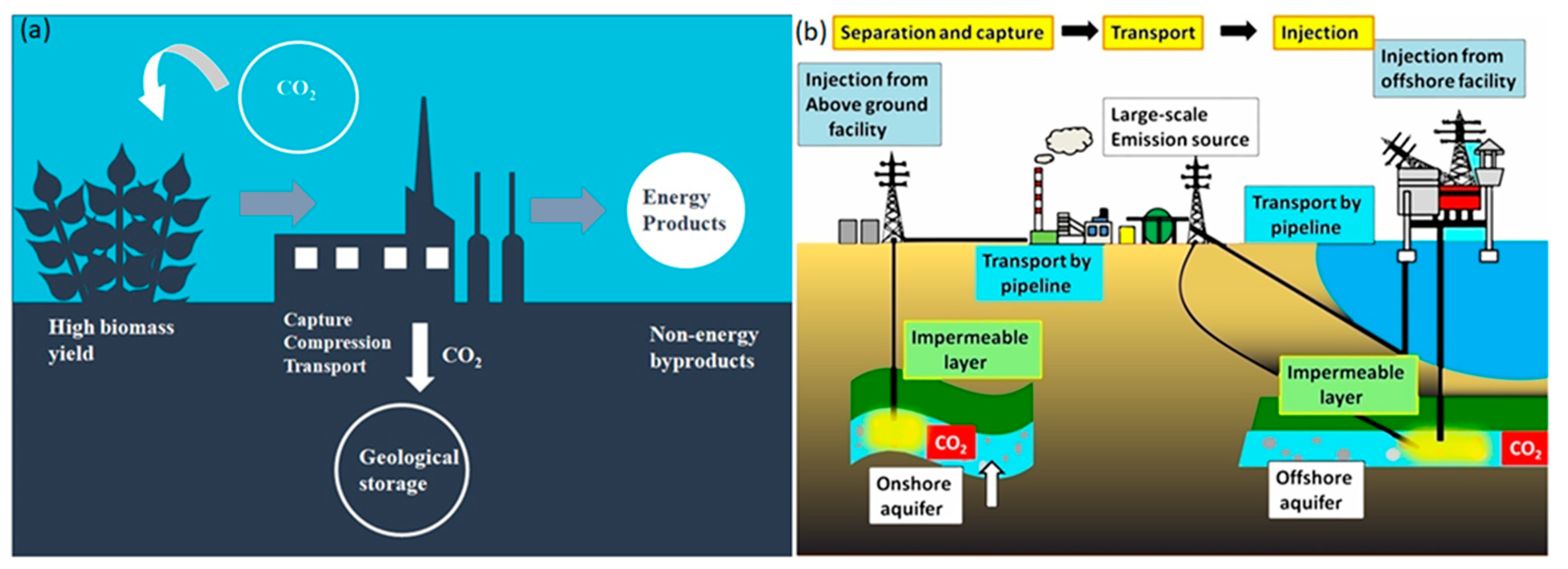
3.3.1. Geological Sequestration

Carbon-capture-storage (CCS) is conceptually simple. It absorbs CO2 emissions from fossil fuel sources and injects CO2 into deep geological rocks, sequestering vast volumes of buoyant CO2 underground (geological sequestration) and reducing ozone pollution. Deep salt aquifers, exhausted oil and gas deposits, and coal seams may act as geological sequestration reservoirs. Injection of CO2 into geological formations for enhanced oil recovery (EOR) is a technology very well developed, and it contains an ample amount of carbon (in the order of Gigatons) (see Figure 1b). Figure 1b shows a flowchart and depicts the different steps required in geologically sequestering the CO2. The technology used to inject CO2 into the soil is already existent and an adequate amount of study has been done on those technologies [85,86]. If the CO2 is collected, the gas stream will be contained deep in geological formations that will keep greenhouse gases from entering the environment as it will be sealed with a natural layer of cap rock having low permeability. The greenhouse gases have been known to cause a myriad of problems in the environment and to the individuals involving a number of diseases and interference in the natural phenomenon [87,88,89]
A lot of research has been done to encourage and aid in geological sequestration of carbon. Geological sequestration poses a lot of risks to the environment if it is not regulated properly. The major problem is to find the best possible sites to inject the carbon so that it does not cause any unexpected harm. Coal can preferentially absorb carbon dioxide over methane at a level of 2–13-fold. Methane recovery is a potential field for carbon dioxide usage, but there are uninvited consequences that come alongside. Carbon dioxide is injected into coal seams, and this can cause a change in the physical and chemical properties of coal. It is always advisable to calculate the degree of alteration it could cause and to make sure that it is below a hazardous level. For this, a few artificial intelligence-based models have been proposed and have been found very useful These models would check the parameters such as interaction temperature and interaction time of carbon dioxide, saturation pressure, etc., and can predict strength alteration.

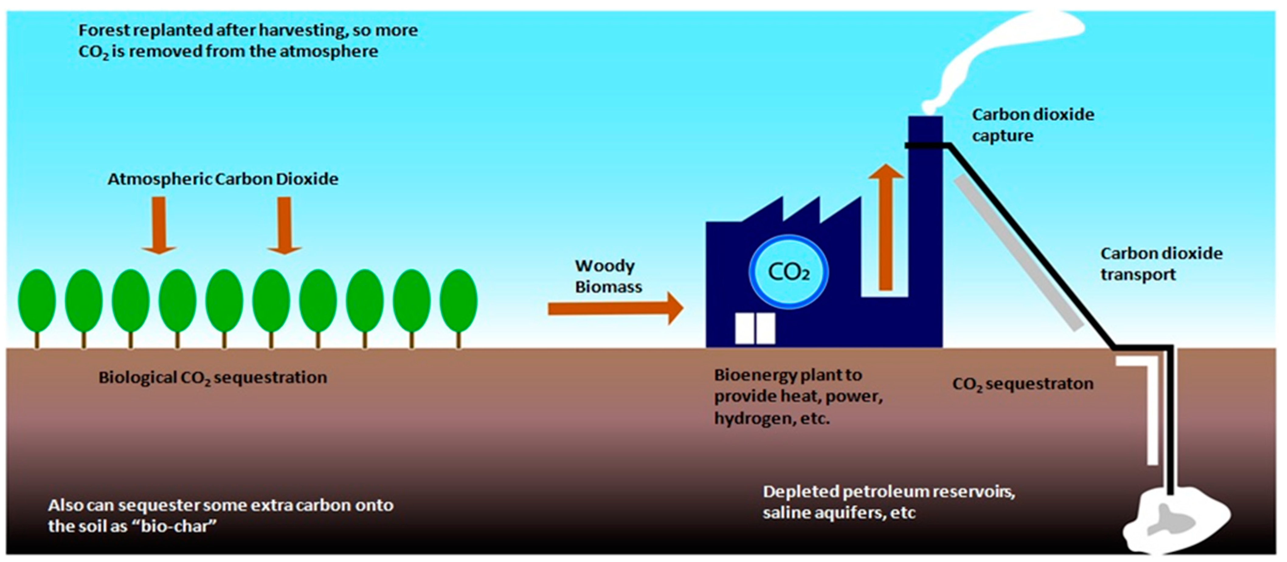
3.3.2. Bioenergy-Based Aspect of Carbon Capture and Storage

The solution that has gained the most attention is biological carbon storage, and it is supported within the environmental community, which includes improving the normal photosynthetic cycle whereby atmospheric CO2 is consumed by rising plants and transformed into organic energy. Many have suggested the concept of planting trees as a means to combat climate change, and this is a smart idea for those concerned with the atmosphere, partially because of the other related environmental advantages of promoting forest production. One of the newer topics of interest in this direction is the bioenergy with carbon capture and storage (BECCS) technology (in Figure 2). Figure 2 shows the pathway of CO2 storage by means of bioenergy, in which the trees absorb the atmospheric CO2, and biomass is then sent for treatment in bioenergy plants for CO2 capture. The captured CO2 is then transported to the subsurface and is stored further. It is a negative emission technology, by production of energy through the combustion of biomass, it has been estimated that if employed properly the BECCS process could deter the carbon dioxide emissions and save the United States alone about a gigaton of CO2 emission by the year 2050. However, BECCS requires large amounts of land for the growing of biomass to be used as fuel, and it can prove harmful for the growth of agricultural crops [90,91,92,93].

3.3.3. Artificial Intelligence in Carbon Storage

Carbon dioxide storage in underground reservoirs is subject to possible difficulties and influenced by a variety of variables, which may well emerge during and/or after the injection stage. The most serious possible issue is leaking. Over time, the reservoir seal is breached by the high injection rates of buoyancy and reservoir pressure. Here, the capillary breakout is guided by reservoir fluids’ interfacial tension. To provide proper containment over time, comprehensive examinations of the IFT behavior and formation fluids are necessary for any individual subsurface reservoir considered for long-term CO2 storage. Thus, the ecosystem functioning and climate change implications are tracked by dynamic monitoring of carbon storage in forest resources. To examine the relative prediction accuracy of different models, four common statistical measures of prediction accuracy are used: average percentage error (APRE), average absolute percentage error (AAPRE), root mean square error (RMSE), and coefficient of determination (R2). Six neural network models are evaluated using different algorithms, out of which three developed multi-layer perceptron (MLP) and the rest developed radial basis function (RBF). The RBF models optimized with the particle swarm optimization (PSO) and farmland fertility (FFA) methods both outperformed the brine solutions in terms of IFT prediction performance. Taking into consideration all 107 data records, both RBF models had a prediction performance assessed by RMSE 2 > 0.99.
Zhang et al. estimated forest aboveground carbon (AGC) and examined its spatiotemporal variations over the past two decades using a Random Forest (RF) technique and multi-year Landsat data. The testing samples’ standardized residuals in different models were all in the range of −2 to 2, demonstrating that the optimized RF model has strong stability and dependability in forecasting forest AGC with reasonably high accuracies (86.86 percent and 89.47 percent).
A simulation approach was integrated by Mohammadpoor et al. with artificial intelligence techniques to forecast the complicated behavior of coal bed methane (CBM) reservoirs. CMG software is used for the first stage of simulation. A dual-porosity model was created to account for the best circumstances during CO2 sequestration and, as a result, the best methane recovery from coal bed reservoirs. The gathered data from the simulated CBM reservoir was further used to train the ANN model and as input for the network, several coal seam properties such as pressure, porosity, thickness, permeability, temperature, etc., are considered. The amount of CO2 injected and the outlet methane produced to determine the efficiency of the model and the R-squared value for the above were 0.92 and 0.94, respectively.

3.3.4. Storage Using Metal-Organic Frameworks

Another technology that has garnered massive importance in the recent past is the use of metal–organic frameworks (MOFs) for capturing CO2 that could be employed in power plants across the globe reducing carbon dioxide emissions via pre-combustion carbon capture. MOFs can be made with a huge variety and are tunable in nature, thus, they are such intriguing technologies in the field of carbon capture and storage (CCS). However, the large variety of MOFs is as much a curse as much it is a boon because with an existence in the order of millions, it becomes exceedingly difficult to underpin the best possible MOF which can be used in storing the CO2. In a recent research by Chung et al. [94] a genetic algorithm was applied to identify the best MOF out of a database consisting 55,000 MOFs and it was found that NOTT-101 had the highest CO2 bearing capacity of all the existing MOFs. MOFs are considered to be efficient storage materials for gases owing to the fact that they possess pores (of the order of nanometers in diameter) and have intriguingly high values of surface area. Owing to the large surface area, a large volume of CO2 can be stored in an MOF. In one of the previous researches, an MOF that can segregate between CO2 and other gases that are released from the exhaust of a power plant was designed. Chemical processing of the fuel at the inlet of the power plant leads to the production of CO2 and H2 and the CO2 can be captured by the MOF. Selective MOFs having high adsorption capacity at high pressure and low pressure are depicted in Table 1. Maximum capacity at high pressure is observed in MOFs with high surface area; however, at low pressure the maximum capacity is governed by functionalized surfaces.

4. Transporting the Stored CO2

Transportation is the path that connects CO2 emitters and storage locations. There is a certain amount of expenditure needed for transportation as well. There are many requirements for selecting the best suitable material and the chosen operational setup. All these uncertainties induce a hint of conservativeness in the design of the systems. The major challenge in transportation technology lies in the reduction of costs and complicacies in design. These processes are also important for bringing a change in the way the carbon-capture-storage (CCS) networks function.
Transportation methods are either networks of pipelines subjected to pressures or by transporting via ships. The efficiency of these methods is dependent on the quantity and distance of transportation. In both modes of transportation, first the compression of fluid is done. In the next stage, the steam is taken to a supercritical state, and this is done so that the greater density in these phases is advantageous to us [112,113]. In the case where CO2 is transported via pipelines, the denser phase is given preference since operating at temperatures more than critical temperature is not desired because of the heat transfer that causes cooling [114,115,116]. The amount by which the fluid is compressed is a function of the volumetric flow rate and also on the pressure drop, which is developed along the length of the pipeline. This drop in pressure is in itself a function of the thermophysical and hydrodynamic properties of the fluid flowing in through the inlet. While the designing of the transport systems is done, all the mentioned factors become exceedingly important. Additionally, these properties depend on the composition of the stream. For optimizing the transportation cost and minimizing shipping, it is important to weigh all the factors like, Composition of the CO2 stream undergoing transportation, the compression/liquefaction stage in transportation operation, etc. One of the really interesting factors to consider is the mode of transportation. There are basically two modes of transportation of the stored carbon-dioxide and a detailed information about both these modes are as follows:

4.1. Available Modes for Transporting the CO2

As discussed in the sections above, there are majorly two kinds of transportation that are used, through pipelines and transportation through ships

4.1.1. The Pipeline Mode for Transportation

While designing pipelines for CO2 transportation it has to be made sure that they are totally safe and do not pose any kind of threat, but at the same time, it has to be made economically efficient. The study of pipelines consists of various subcategories, which focus on studying the designing, safety, management, etc., of the pipelines. All these subcategories themselves qualify to open the doors for further research, as it can be seen in Figure 3. Under normal conditions of operation, the flow rate and hydrodynamic properties of the inlet CO2 stream decide the design requirements of the transportation operation. Although it is important to monitor that there should not be any phase change because phase change leads to the formation of liquid slugs and to prevent this situation from arising, pressure and temperature at the inlet point are chosen in a manner so that the fluid does not change its phase inside the pipeline. Additionally, it must be totally clear that pure CO2 is not fed as the feed, as stream composition is an important design parameter of a pipeline. Apart from this, it also affects the vapor–liquid equilibrium. The type of impurities in a stream can affect the material selection for building the pipeline.
There is a significant capital requirement to transport CO2 over large distances via pipelines, and there have been many studies focused on the direction of developing a financially optimized pipeline network [115,117,118,119,120,121]. In the case of network designs of pipelines, there is a trunk pipeline at which various emitters can be linked and due to this, there is a benefit since a shared infrastructure can be provided in which more sources can join as carbon-capture-storage (CCS) [122,123,124]. The trunk pipeline is always made oversized so that it can contain the growth in the volume of CO2 being transported [125]. It was found in some studies that while load changes happen, there are chances that the fluid undergoes a phase change and this leads to an operational problem [126]. It was found that there is a considerable effect on the dynamic behavior of fluid, and these effects arise because of the CO2 streams [127]. In total, the length of CO2 pipelines across the world is 6500 km [128], and most of these are situated in sparsely populated areas, and in order to build pipelines in the more densely populated areas, researchers are working to develop high fidelity instruments that can perform the task of assessing the risks associated with this in a quantitative manner [129,130,131,132,133,134]. These analyses help in mitigating the needless aspects while designing. For designing a pipeline at its optimum cost, it is important that those materials are chosen which are economical but also serve the purpose of transportation without any compromise. However, design parameters like the diameter of the pipe is one of the most important factors that lead to determining the cost of the pipeline system. Scientists have tirelessly worked on determining the factors that determine the diameter of a pipe and have tried to devise different formulae for the same, which results in giving the optimum pipe diameter. Some of those correlations are mentioned in Table 2
One of the most daunting tasks for an engineer is designing the standards and specifications, as it is an extremely exacting task that demands sharp skills and solid research. In the designing of CO2-based pipelines, the availability of standards and specifications are pretty minimal as compared to the ones available for the pipelines transporting oil and gas. On a worldwide basis, only 15 standards could be found for the pipelines carrying CO2, and Figure 4 shows that the most common standards for CO2 pipelines are DNV (Det Norske Veritas) and ISO (International Organization of Standardization).
It is extremely important to select the proper quality of steel for the pipeline so that it is able to resist any kind of failure and corrosion and also be cost-efficient [124,128]. It is decided whether steel is suitable or not by looking at its fracture propagation resistance ability. Fractures can happen by corrosion or by the interference of some external sources. Providing external coatings for protection, cathodic support, etc., are the few ways that are used to prevent the corroding of CO2 pipelines [128].
The transportation operation, just like any other process, inflicts some risks that alter the smoothness of operation. However, there are always precautionary measures available to mitigate the chances of transportation-related risks. In order to reduce the probability of these unfortunate events like leakage, there are measures like minimizing the distance of transportation and reducing the percentage of highly toxic gases like sulfur dioxide, etc., in the CO2 stream that has been captured. In addition to these measures, which are the most generally used, there are other precautions that can be taken, like processing the CO2 stream before subjecting it to transportation or building the pipeline system through areas that are sparsely populated. By doing this, a very low percentage of people would be exposed to the risk of leakages and thus the most preferred routes are the ones through hilly terrains.

4.1.2. Ship-Based Transportation

The article discussed the transportation modes to be pipelines and ships, but shipping transportation is the one that has received very little attention, as this mode of transportation is in its incipient stage [142,143]. There are very few numbers of ships that are being used currently for CO2 transportation even when this is very similar to Liquefied Petroleum Gas (LPG) transportation via shipping. Over large distances, shipping mode is preferred over pipelines [144,145,146]. The ships carry the CO2 from one source and distribute it to the customers through pressurized cylinders. It was found that most of the costs incurred in shipping are due to operational expenditure while in the case of pipelines, the capital expenditure is more and as discussed earlier, a massive chunk of this operational expenditure is required in the compression process [147]. Therefore, the requirement of reducing this cost is extremely important like designing the injection system. Apart from the costs needed to build the ships, there is an important necessity to invest in loading and unloading systems, in liquefaction units, etc. There are other operational costs as well, like the cost of labor, electricity, fuel for the ships, and maintenance. The costs incurred in transporting CO2 via ships are much more than the transportation of other energy sources like liquefied petroleum gas (LPG). This can be understood by the fact that since liquefied CO2 is denser than liquefied petroleum gas (LPG), the load on the ship is much more in the carriage of CO2 than it is in those ships that are carrying liquefied petroleum gas (LPG) or liquefied natural gas (LNG) [148,149].

5. Development of CO2 Utilization Technology

CO2 capture and utilization have now become an increasingly popular domain related to carbon capture. Carbon-capture-utilization (CCU) finds applications across farming and greenhouses to convert into fuels, chemicals, polymers, and building materials. Carbon-capture-utilization (CCU) basically adds value to the carbon capture process because originally carbon was simply buried underground. Polymers can play an important role especially polyurethane networks when it comes to development of technologies for utilization of carbon. Recent researches show that reprocessibility and recyclability for a polyurethane have been enhanced and could come to use in these fields [150,151]. Through a number of simple conversion processes, this carbon can be made useful.

5.1. Development of a Newer Fuel-Cell Technology That Produces Electric Current from CO2

Due to the growing concerns of global warming, carbon-capture-storage-utilization (CCUS) is gaining prominence because of its ability to nullify the carbon emission and it has been found that a fuel cell has the capacity to eliminate CO2 and also produce electricity [152,153,154,155,156,157,158,159]. One such development is based on the phenomenon of the dissolution of CO2 into water. Since an acidic solution is produced due to the dissolution, it was realized that an electrochemical reaction can happen and thus, a battery can be created. As can be seen in Figure 5, the anode is composed of sodium metal, which is put in an organic electrolyte while the cathode is composed of platinum. The reaction is initiated by bubbling CO in water and as a result of which H2 liberation happens at the cathode and the flow of current starts in the circuit. The H2 thereby produced can be used as a fuel for various purposes.
SOECs have been made for creating renewable fuels and energy transporters, which will enable renewable energy to be transported and stored [160]. Notwithstanding encouraging pre-commercial examples, certain significant technological obstacles must be overcome before this technology may be commercialized. Lowering capital costs through low-cost material and cell architectures, as well as advances in electrode performance and longevity, the cathode, are among them. The traditional Ni-YSZ cathode is shown to have been encouraging talk about performance during the initialization step; yet, to avoid nickel oxidation to nickel oxide, a constant supply of precious reducing gas is required, and rapid deterioration can be seen because of nickel migration and deactivation. For the electrolysis of dry carbon dioxide without the need of extra protective gas, Kaur et al. [160] demonstrated efficient and stable dual phase electrodes relying on A-site deficient lanthanum ferrite and doped ceria. In a simple, inexpensive, and scalable tubular cell, the material was utilized for both anode and cathode, and both electrodes were coated at the very same times, decreasing manufacturing time. When just dry carbon dioxide was utilized as the input gas and no extra reducing gas has been utilized, the new LSCF-GDC electrode produced considerably more CO than the state-of-the-art Nickel-YSZ electrode. This method offers a strong argument for continued design and validation of non-nickel-based electrodes for use in solid oxide electrolysis systems [160].
On the permeate side, Chen et al. [161] devised two membrane processes for use with a SOFC setup, one with an air sweep (SOFCMBair) and another with a vacuum (SOFC-MBvac). The developed membranes’ transport characteristics had been implemented to the operations, and a techno-economic analysis (TEA) was performed to determine the cost of carbon dioxide removal for every operation. Importantly, with 100 percent anode exhaust recycling, the system fuel consumption for both operations may be increased to greater than 99 percent. A steam-to-carbon ratio of more than 1.5 can be achieved by fine-tuning the stack fuel usage. The SOFCMBvac method was discovered to have a cheaper carbon dioxide removal expense than the SOFC-MBair method. When evaluating the recovered fuel price in the SOFC-MBvac method, the CO2 removal expense is not only completely offset by the recovered fuel price, but there is also a profit of around 38 dollars/tonne of carbon dioxide captured. Furthermore, using a forty dollars per tonne CO2 selling price for increased oil recovery, a profit of nearly 66 dollars/tonne of carbon dioxide captured may be realized. Moreover, creating membranes with larger CO2 permeances might result in greater profit. Furthermore, the SOFC-MBvac method allows for zero-carbon electricity generation.
Other application of Carbon dioxide use is the photocatalytic reduction of CO2 to convert hydrocarbons. Nevertheless, photocatalytic CO2 reduction’s low yield and product selectivity pose substantial hurdles to its broad use. To solve this critical problem, Xie and colleagues [162] created a coupled system that combines photocatalytic CO2 reduction with photocatalytic fuel cells (PFC) for carbon-dioxide energy production. Under this combined systems, the results of photocatalytic CO2 reduction serve as fuel for the PFC, which generates electricity directly. Just in the carbon-dioxide presence as the supply during illumination is direct power production by this linked system shown. Furthermore, the fuel levels at the PFC exit are much greater than at the PFC intake, suggesting that the coupled system described in this work is capable of generating energy as well as yielding solar fuels. This research provides up a novel path for CO2 to be used in direct electricity production.
Consonni et al. [163] found out that when standard amine technology is used to capture CO2, the efficiency drops below seventy percent. Steam CH4 reforming and auto thermal reforming are two common methods for producing H2, and they now account for the majority of producing H2. These activities emit roughly 8.7 kilograms carbon dioxide for every kilogram of H2 generated if CO2 is not captured. Consonni et al. [163] suggested a molten carbonate fuel cell process with CO2 capture to refit the flue gas flow of an existing Steam CH4 reforming plant rated at 100,000 Nm3 h—1 of 99.5 percent pure hydrogen. Direct CO2 emissions may be decreased by >95 percent, to 0.4 to 0.5 kg carbon-dioxide per kilograms hydrogen, whilst creating 17 percent extra hydrogen, according to the thermodynamic study. The efficiency loss linked with capturing CO2 is modest because of the carbonate fuel cell’s increased power and H2 production, decreasing the SMR efficiency from 76.6 percent without capture to 75.6 percent with capture. This illustrates the carbonate fuel cells’ synergistic quality, since they can convert natural gas to hydrogen even while collecting CO2 from the SMR flue gas and generating power, resulting in a complete system with extremely low emissions and great efficiency.

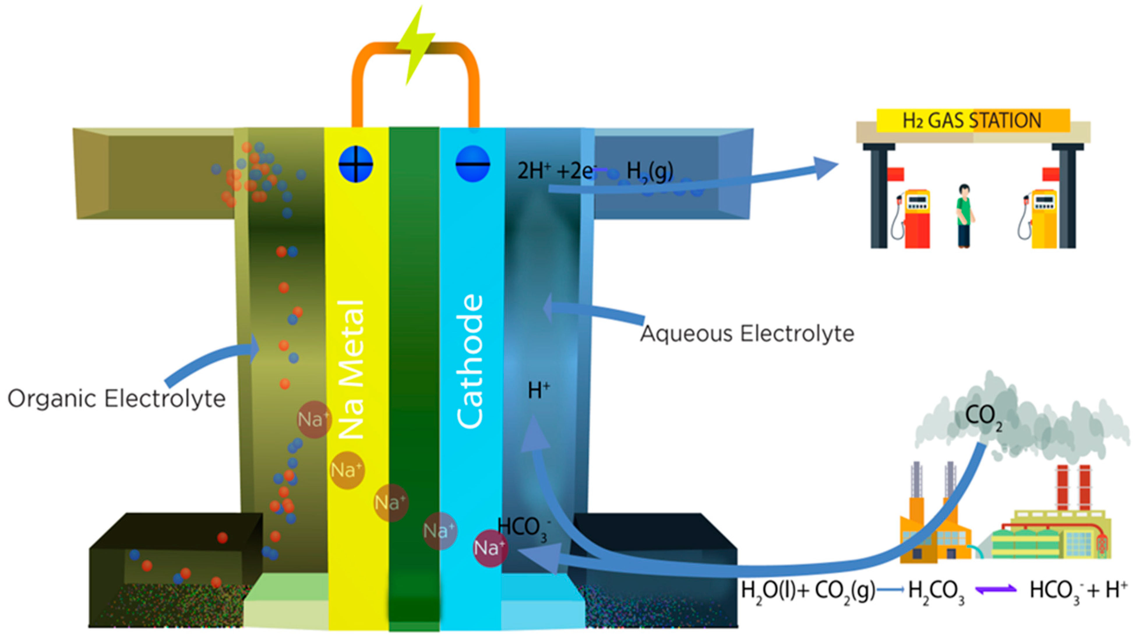
5.1.1. Development of a Novel Fuel Cell: Generating Electricity and Mitigating CO2 Levels Simultaneously

For mitigating the levels of CO2 available in the air alongside making the most out of this gas known for its harmful greenhouse emissions, the method of electrochemical conversion is deemed to be a futuristic approach in producing hydrocarbons from CO2. The greenhouse gases if not controlled are not only causative factors in climate change, but can also bring about diseases to humans, like lung cancer, which lies among the deadliest of cancers in the world and especially United States [164]. For achieving the conversion of CO2 into compounds like CO or CH4, the electrochemical conversion is a widely considered method. However, considering the fact that this method is only in its nascent stages, it is unlikely that it would have the ability to have a practical application and the main reason for this is the higher energy that it demands. These high energy demands still exist even when catalysts are used to facilitate the electrochemical conversion of CO2 [165,166]. It has been reported in various experimental conclusions that the employment of catalysts like copper and silver requires an extra potential of about -1 Volt against a reversible hydrogen electrode and thus, it is important to find a solution to reduce or even nullify this extra potential [167]. It has been reported that a novel CO2/H2 fuel cell has been developed that does not consume electricity, but on the contrary, it is an electricity generator and at the same time it produces CH4 (a synthetic fuel) from CO2 [168,169,170,171,172]. Hence, it can be said that it can be easily differentiated from the conventional electrochemical cell owing to the electricity generation property [173,174]. In this cell, the production of H+ ions happens at the anode owing to the oxidation of H2. Thereafter, the H+ ions travel through a proton exchange membrane and result in the production of CH4 because of reduction reactions happening at the cathode. It has been seen that these cells are better performers at a higher temperature range, which makes them extremely potent for usage in thermal power plants. In a majority of conventional electrochemical fuel cells, the oxidant at the cathode is O2, but in this particular cell, the oxidant is CO2 [175]. This cell makes use of a polymer named phosphoric acid-treated-polybenzimidazole (PA-PBI) as a proton exchange membrane [176]. This is an extremely stable polymer based on its thermal properties. The chemical reactions governing the working of this fuel cell are mentioned beneath [177,178,179].
Anode:
H2→2H+ + 2e→E = 0.000 V vs. SHE
Cathode:
CO2 + 4H+ +4e→C + 2H2O E = 0.210 V vs. SHE
CO2 + 6H+ + 6e→CH3OH + H2O E = 0.210 V vs. SHE
CO2 + 8H+ + 8e →CH4 + 2H2O E = 0.210 V vs. SHE
2CO2 + 12H+ + 12e→CH2CH2 + 4H2O E = 0.210 V vs. SHE
2CO2 + 12H+ +12e→CH3CH2OH + 3H2O E = 0.210 V vs. SHE

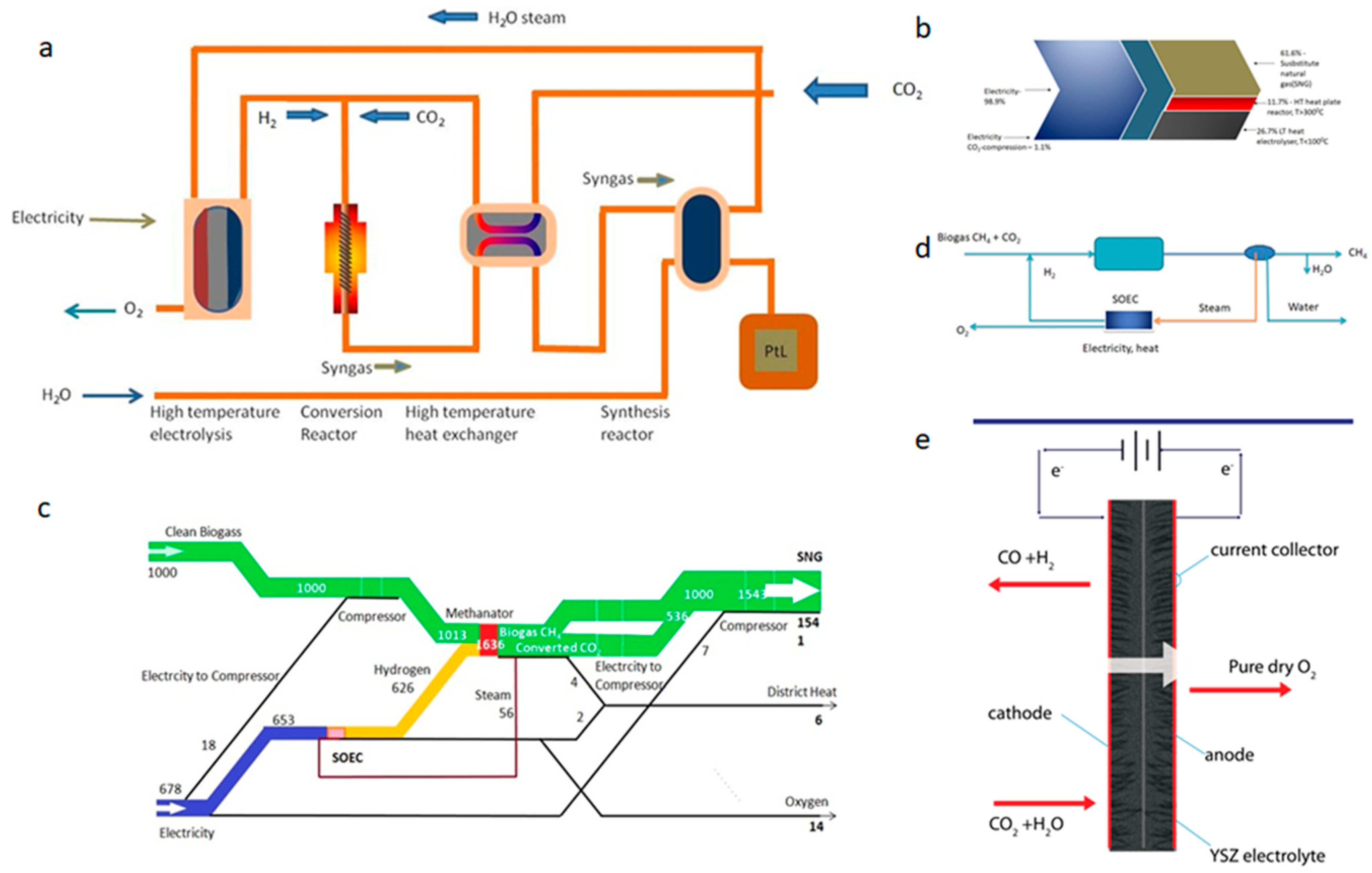
5.1.2. The Progress in Oxygen Regeneration Owing to the Integration of Solid Oxide Co-Electrolyzer (SOCE) and Carbon Formation Reactor (CFR)

In the case of a spacecraft life support, the crew produces CO2, which is to be removed, and the recovery of the oxygen is to be done. This recovery is done by subjecting CO2 through reduction reactions, and the process that is being employed to carry out this reduction process is called the Sabatier process. In the reactions of the Sabatier process, the reduction of CO2 is done to produce different products like methane and water. In the succeeding step, the electrolysis of water is carried out through the oxygen generation assembly (OGA). In the oxygen generation assembly (OGA), the process of oxygen recovery is completed and the methane is allowed to ventilate. Upon calculation, it was found that the rate of recovery for oxygen is about 50%. There is a loss of 2 moles of H2 per mole of CH4 that is vented, and thus to compensate for this loss, there is an essential requirement to supply hydrogen again. The amount of hydrogen supplied for each person is about 33 kg per year. This hydrogen is generally made available from water, which means that for producing 33 kg of H2, there is a need for 298 kg of water. In order to augment the recovery rate for oxygen, the carbon to the hydrogen of the product hydrocarbon should be enhanced from that of CH4. For this purpose, a plasma pyrolysis assembly (PPA) has been developed, and it is known to convert CH4 into acetylene (C2H2) and enhance the carbon to hydrogen ratio. This technology has been successfully tested by NASA and the conversion fraction for the same is as high as 0.9 [180,181]. When this technology is combined with the Sabatier process, the oxygen recovery rate can be elevated to a level of 78% from the 50% mark. For an even elevated recovery percentage, the reduction of CO2 should be done. There have been some significant developments marked by a CO2-H2O system, which is a doubly staged system with solid oxide co-electrolyzer (SOCE) cells and carbon formation reactor (CFR) cells. The presence of these can elevate the oxygen recovery levels to the 90% mark with added benefits of having lower power and volume required for resupply.

5.1.3. Operational Mode of Solid Oxide Co-Electrolyzer Cell

The solid oxide co-electrolyzer (SOCE) is composed of 2 electrodes, and between them is a membrane of yttria-stabilized zirconia (YSZ), as can be seen in Figure 6e. As it can be seen in Figure 6e, at the cathodic end, CO2 and H2O are fed as gases and at a potential difference of 1 to 2 volts. The reactions governing the conversion here are:
CO2 is dissociated to CO and oxygen ions (O2−), and H2O dissociates into H2 and O2−
CO2 + 2e→CO + O2−
H2O + 2e→H2 + O2−
CO2 + H2→CO + H2O
The working of a solid oxide co-electrolyzer (SOCE) is very similar to that of a reverse water gas shift reactor and an H2O electrolyzer. It is more like the combination of both in a single machine and has the potential to level up the fractional conversion of CO2 to CO. That is because its operating temperature is as high as 800–900 degrees Celsius, and owing to these temperature ranges, there is a shift in the chemical reaction mentioned above. Due to this, there is a shift in the equilibrium in the rightward direction and thus, the equilibrium conversion is increased. Additionally, there is electrolysis of H2O, and removal of O2 happens to form the cathodic end. Owing to this, the concentration of H2 increases, and the above chemical reactions shift in the direction of higher equilibrium conversion. If in case there is an installation of the solid oxide co-electrolyzer (SOCE) for the purpose of rejuvenating the air, there are massive changes that the H2O electrolyzer can be eliminated, and the resupply of extraneous volume can be mitigated. A doubly staged solid oxide co-electrolyzer (SOCE) oxygen system is advantageous in terms of the amount of oxygen recovery because of the higher conversion of CO2 into oxygen, which is obtained from the coming together of solid oxide co-electrolyzer (SOCE) and Carbon Formation Reactor (CFR) [182,183,184].

5.1.4. Carbon Formation Reactor (CFR) and its Mode of Operation

With the help of a carbon formation reactor (CFR), it is possible to form elemental carbon in the solid form from CO2 and CO. This conversion is carried out with the help of Bosch and Boudouard reactions.
(Bosch reaction)
CO2 (g) + 2H2 (g)→C (s) + 2H2O (g)
(Boudouard reaction)
2CO (g)→C (s) + CO2 (g)
As discussed in the preceding section, a doubly staged system leads to higher regeneration of oxygen. Initially, the CO2 is reduced to CO and this conversion happens inside a solid oxide co-electrolyzer (SOCE) cell. The first-pass conversion is improved by separating the Bosch reaction. It has been ascertained that in the first-pass through the solid oxide co-electrolyzer (SOCE), the conversion obtained for CO2 and H2O is about 80%. Due to highly concentrated CO and H2 inputs, the Carbon Formation Reactor (CFR) performs better by having better efficiency. It has been seen that about 70% of oxygen can be recovered by this two-staged system. Theoretically, it is possible that even 100% of oxygen can be recovered by the process of recycling the outlet stream of the carbon formation reactor (CFR) gas, but since it is impossible to reach the 100% mark, it can be practically said that around 90% of the oxygen can be recovered [185,186,187].

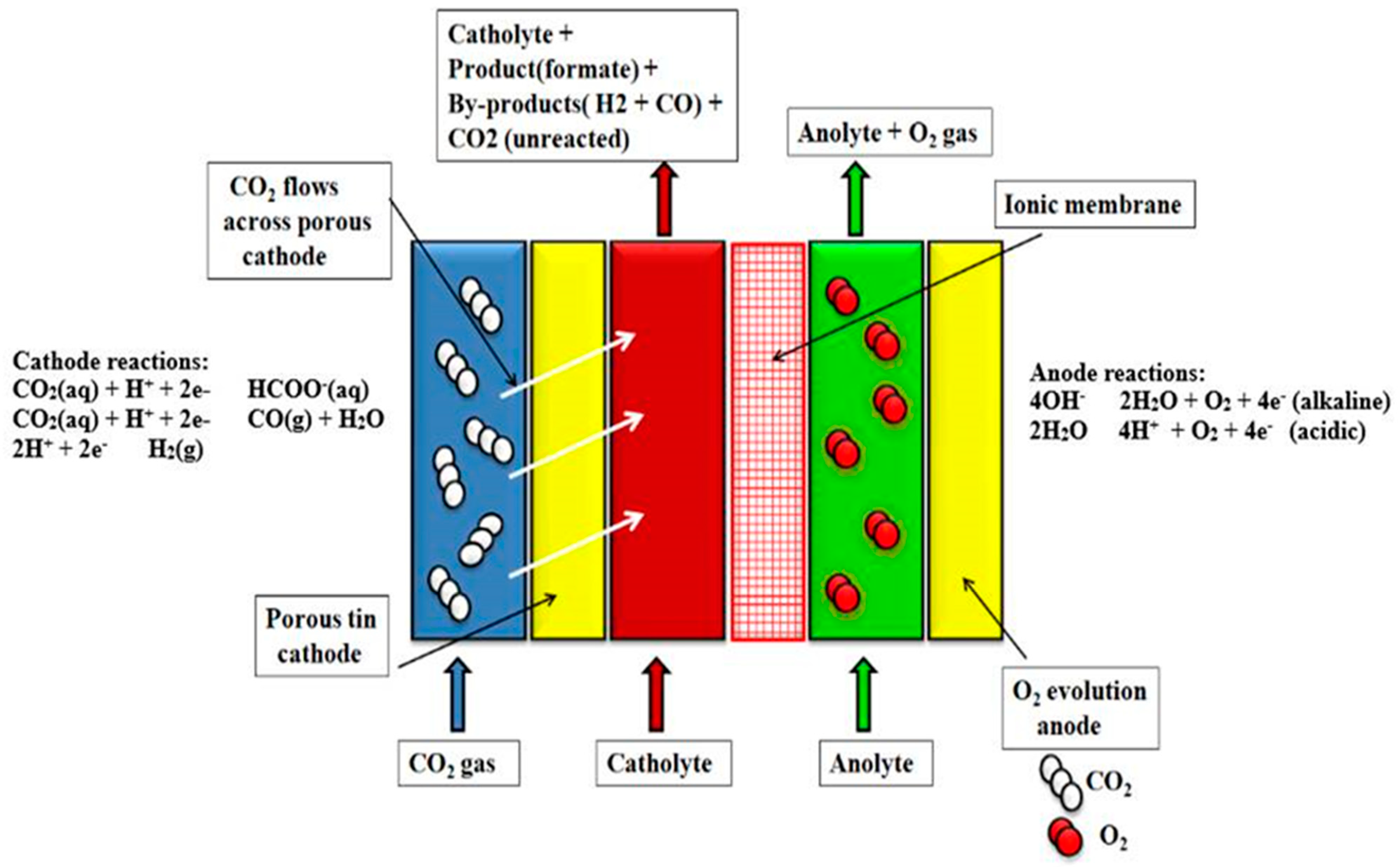
5.2. Electrochemical Conversion of CO2

The electrochemical conversion of CO2 is the process wherein the CO2 is transformed into reduced chemical substances. The origin of this process dates back to the 19th century when this method was used to convert CO2 into CO. The cathode was made up of zinc. However, ever since the late 20th century, the importance of the electrochemical conversion of CO2 has been growing because of the increasing demand for renewable fuels, as well as stricter restrictions imposed on CO2 emissions. Other common sources of renewable energy like solar, wind, etc., have been able to cater to only 30% of the total energy needs, and this is one more reason behind the growing prominence of electrochemical conversion. In electrochemical conversion, CO2 is transformed into syngas, methane, and other fuels, and thus there is great potential in electrochemical transformation.
A company named Sunfire GmbH has designed a process to produce a syngas that lays its dependence upon electrolyzing H2O and CO2 at very high ranges of temperature. This process is carried out with the help of a strong oxide electrolysis cell (SOEC). The syngas can then be converted into fuel, which can later be used [188]. The strong oxide electrolysis cells (SOEC) operate at pressures exceeding 1 MPa and high temperatures (>800 °C).
The steam then gets divided into hydrogen and oxygen. In this method, with the help of the Fischer–Tropsch process, the syngas is converted into Blue Crude, which is a hydrocarbon with long chains (-CH2) and is later used to produce synthetic compounds. This is an exothermic process and water is disintegrated for steam electrolysis with the help of the heat released from the process (see Figure 6a). Figure 6a depicts the method of producing blue crude by the process designed by the company named Sunfire GmbH. The complete unit is comprised of a high-temperature electrolyzer that separates the incoming stream of steam into H2 and O2, a conversion reactor for producing syngas, a heat-exchanger for enhancing the temperature of the syngas, and finally, a synthesis reactor that produces the end product named Blue Crude. Thus, elevated productivity is achieved [188,189]. There are various companies like SunfireGnbH, Nordic Blue Crude AS, ETOGAS, etc., which have been working on providing more efficient and cleaner fuels, and they have invested considerable efforts for the same. For instance, ETOGAS has built a procedure to produce H2 from soluble pressurized electrolysis of H2O. This H2 then forms CH4 upon reaction with carbon dioxide [188]. In one of the plants of ETOGAS, testing of biogas updating is done and it was also assembled with an automobile plant of a capacity of 6 MegaWatt equivalent power. The plant produces Audi AG automobiles and is situated in Germany. Three 2 MWe units deliver engineered methane or Audi e-gas, which has 96% methane concentration. The plant delivers around 1000 tons per year of Audi e-gas, artificially restricting somewhere in the range of 2800 tons of CO2. Upon increasing the number of electrolyzer units, the unit size can be scaled to a higher level [188,190]. Figure 6b shows the vitality productivity of the PtG procedure. Danish organization HaldorTopsøe built up a methanation process called TREMP™. It had three adiabatic fixed bed-reactors, which make use of catalysts for methanation [190]. The heat that is released due to this methanation process is recuperated and is put into use for producing steam at very high-temperature, which is then utilized in the solid oxide electrolyzer cell (SOEC) unit. HaldorTopsøe has shown a high-proficiency process that can lead to yield CH4 at a flow rate of 10 m3/h (Figure 6d). The percentage of methane converted from electrical power is around 80% (Figure 6c).
The power that is used up is 290 kWh/ton of CO2, the new water utilization is 1.6 tons/ton of CO2, and also, there is no waste-water or different emanations from the procedure [188,190,191]. A company named DNV GL built an ECFORM procedure to change over CO2 into formic corrosive and formate salts. This procedure includes an electrolysis reactor, which is depicted in Figure 7. It makes use of a tin-based amalgam as cathodes to form formate salts from CO2 while, O2 is produced at the anode. Additionally, the reactor consists of an ionic membrane as well. The reactor cell potential is low and resistive misfortunes that bring about expanded vitality productivity of the procedure that makes it all the more financially plausible [192]. The energy that is consumed by the cell is approximately 5.5 MWh/ton, and it can be sufficed by renewable energy in total. The company has created a semi-pilot ECFORM showing reactor. The limit of diminishing is around 1 kg of CO2 per day. By utilizing 1 ton of carbon dioxide, 1.04 tons of formic acid formation takes place, speaking to, for all intents and purposes, a proportional reduction of CO2 [188,192]. This procedure is prepared to scale up; however, innovative head-ways are required before huge scope creation can occur. A group of researchers has been building up the C2CNT procedure, which can change over CO2 into carbon nanofibers (CNF) and carbon nanotubes even at low voltages. Carbon composites possess a wide assortment of applications, for example, batteries, gadgets, etc., which are in contrast to metals that are employed in airplanes, opulent vehicles, and sports gear. In the method of C2CNT, CO2 rises and disintegrates in a liquid carbonate shower. The CO2 is parted by electrolysis at anodes submerged in the liquid shower into O2 at the anode and carbon as unadulterated carbon nanotubes at the cathode. Upon varying some parameters, it is possible to control the arrangement of carbon nanofibers nanotubes that can be controlled, and then the item structure can be tuned for a particular application [193,194,195,196]. The C2CNT procedure can be utilized to catch CO2 straightforwardly from different sources. Researchers have developed some structures for making the frameworks fit for application in gaseous petrol and coal-terminated power plants, where CO2 is captured and converted into carbon nanotubes or nanofibers, and unadulterated oxygen. The utilization of this oxygen is done to improve ignition and thus, the plant has zero CO2 discharges [197]. The creation of carbon nanotubes could be way more beneficial for power plants based on non-renewable sources of energy than it would be for creating power. A traditional natural-gas-fired-combined cycle (NPCC) accounts for the production of power costing as high as US$909 for each ton of natural gas. Additionally, radiation of about 2.74 tons of CO2 takes place for every ton of natural gas. It is also proposed that a joint venture by NGCC and C2CNT plant has the ability to produce power costing ~USD 835 along with the production of carbon nanotubes (approximately 0.75 tons). This quantity of carbon nanotubes cost as much as ~USD225,000 without any CO2 radiation. By this procedure, the expense of delivering carbon nanotubes would be US$2000/ton [198]. In this time, the researchers have gathered their focus on leveling up the C2CNT procedure. In quest of a larger scope, ECFORM, C2CNT, and HaldorTopsøe’s procedures require further research [199,200].

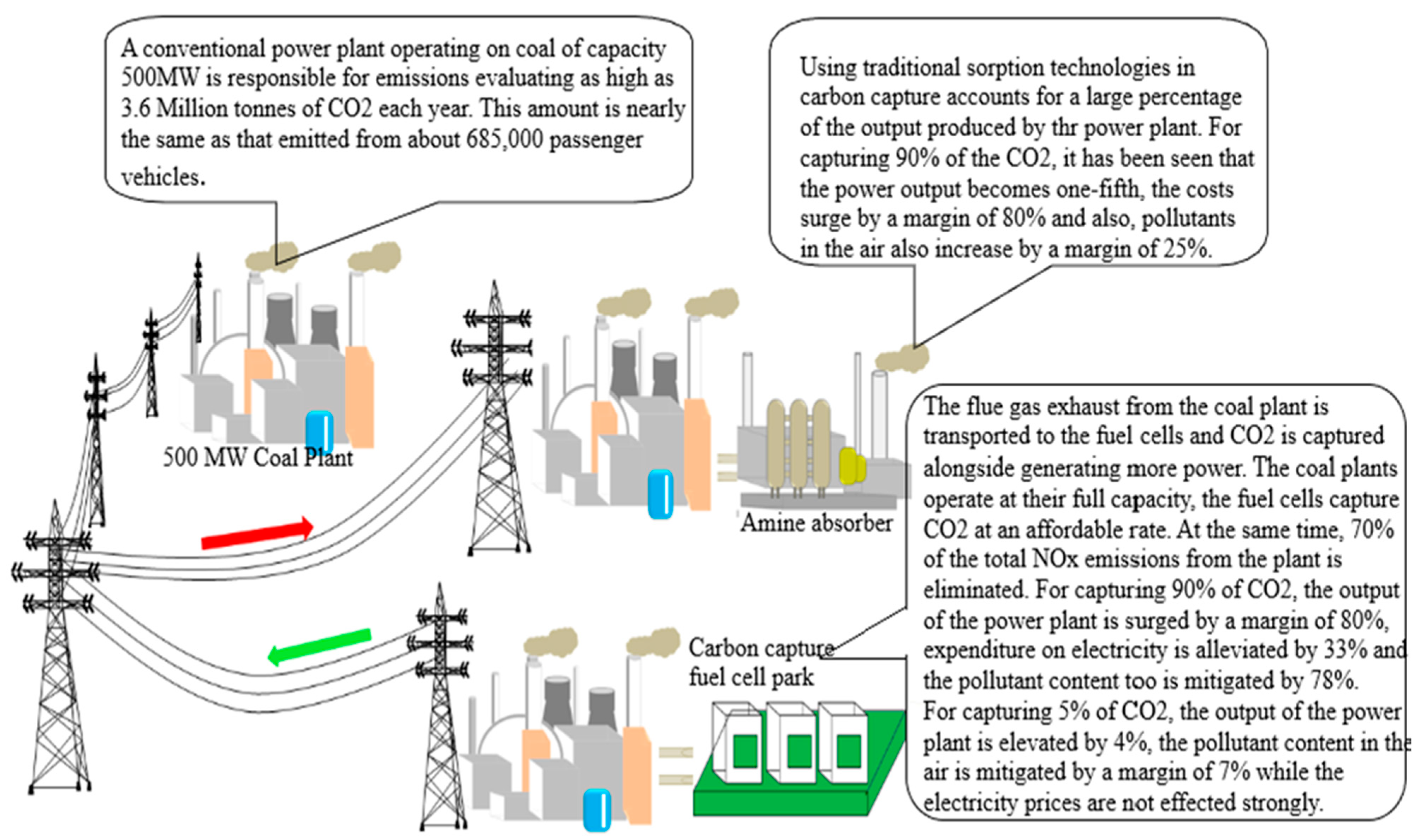
6. Efficient CCUS Technologies and Their Economic Benefits

In the mid-19th century, it was demonstrated for the first time that electricity could be produced from a reaction between hydrogen and oxygen with the help of platinum as a catalyst and to date, researchers have gathered their interests in developing a hydrogen fuel cell in the search for a cleaner fuel [201]. However, due to the lack of technology in hydrogen fuel cells, it has not been an economically efficient replacement for conventional fossil-based fuel. In a few electric plants across the world, fuel cell technology has been proposed that can capture about 90% of the CO2 being emitted from the electricity generating unit [202]. The CO2 can then be recycled as feedstock for the industry. Fuel cells that produce electricity in synchronization with producing hydrocarbons were first probed back in the 1950s and were found to be economically much more viable than the hydrogen fuel cell because these fuel cells were operated at higher temperatures and so the catalyst it used was a cheaper Nickel metal. Additionally, since it can be used in electricity production, it would cause much less of an economic burden. Companies worth in the order of billions of dollars have taken forward the efficiency levels of these fuel cells as they went on to install about 50 power plants with capacities in excess of 50 MegaWatts each [203]. Setting up these many electricity generating plants not only mitigates the use of fossil fuels, which are a major reason for CO2 emission but also produces cleaner energy [204]. Several multinationals have proposed that they can build systems capable of producing as much as 500MegaWatts of power from fuel cells and capture as much as 6.6 million metric tonnes of CO2, which is nearly the emission caused by a million vehicles each year. The above technologies have extreme potential with the everyday developments happening in this field. A proper revenue and returns on investment can be earned by selling the power produced by these fuel cells in addition to making the air free of pollutants. Fuel cell technologies are affordable and can be scaled up and down based on the demands. Fuel cell-powered industries can be enhanced by starting from extremely low levels of CO2 capture that cause little capital inflow. It has been estimated that in order to achieve a capture of about 90%, the costs of power are only elevated by a small margin of 0.02 Dollars per kWh. The fuel cell capture is economically more efficient than traditional capturing technologies, as they are twice as expensive as the fuel cell technologies [205]. As mentioned above, the fuel cells are more power generators than consumers. The conventional capturers reduce the output of a plant by a margin of approximately 20% (Figure 8). Figure 8 depicts the ways in which a fuel cell-based power generation system is better than a conventional power generation system. Developing these technologies in this direction is important, as the fuel cells not only generate a profit (because of electricity generation), but also provide millions of people with a cleaner electricity source [206].
Monitoring worldwide energy demand growth with reducing CO2 emissions is one of the century’s most pressing challenges. Carbon capture and storage (CCS), as per the International Energy Agency (IEA), is a necessary method to drastically cut down the carbon dioxide emissions to achieve the international community’s objective of 26 GtCO2/year by 2030.8. The budget for carbon is expected to exhaust in the upcoming 27 years according to the present global carbon dioxide emissions of 42 Gt CO2 per year [207,208]. Mohsin et al. demonstrated three products of carbon that will cause economic (increment of 10% in gross margin) or environmental advantages (721,000-ton carbon dioxide per year) along the route of carbon capture and utilization. The carbon dioxide source and the access to low power markets are frequently isolated by geography. For instance, this associates the transportation of either collected carbon dioxide or electricity generation, creating concerns regarding the whole process’s economic viability [209,210]. Developing integrated systems in which an electrochemical unit is intimately linked with a suitable carbon dioxide capture procedure, results in an in situ manufacture of superior products [158,211,212].
Zhang et al. [213] demonstrated a cost–benefit study of chemical, physical, and hybrid physical–chemical absorption methods for carbon dioxide capture from a variety of industrial streams with varying pressures and compositions.
The most favored economical process at atmospheric pressure having carbon dioxide concentration less than 30.4 percent is chemical absorption, while for medium carbon dioxide percentage (30.4–59.3%) the favorable process is hybrid absorption, and for maximum carbon dioxide (>59.3%), it is physical absorption. The economic outlook of the three absorption procedures is assessed following simulation and process design. The process total annualized cost is calculated via Equations (12)–(15).
T A C = A C C + A O C
A C C = C R F . C c a p
C R F = d r . ( 1 + d r ) n ( 1 + d r ) n 1
A O C = C u t + α C u t
T A C = T o t a l   a n n u a l i z e d   c o s t
A C C = A n n u a l i z e d   c a p i t a l   c o s t
A O C = A n n u a l i z e d   o p e r a t i n g   c o s t
C R F = C a p i t a l   r e c o v e r y   f a c t o r
C c a p = T o t a l   c a p i t a l   c o s t
d r = D i s c o u n t e d   r a t e
n = E q u i p m e n t   l i f e t i m e
C u t = A n n u a l   u t i l i t y   c o s t
α = R a t i o   o f   o p e r a t i n g   c o s t   o v e r   u t i l i t y   c o s t
As shown in Figure 9a, the cost of electricity overshadows the physical absorption total annualized cost. Figure 9b,c shows three types of feed with varying carbon dioxide content and their cost breakdown value. Compressing the input gas and capturing carbon dioxide consumes a significant amount of electricity. Furthermore, when xCO2f (mole fraction of carbon dioxide in feed gas) grows, the electricity cost somewhat rises. The maximum increment in TAC during chemical absorption is due to the steam cost that is employed to regenerate the solvent (MEA). The quantity of steam required rises linearly with the amount of carbon dioxide, resulting in a substantial expansion of total annualized cost. When compared to chemical and physical absorption, the hybrid absorption technique can reduce total annualized costs by up to 0.7 and 3.1 million dollars per year, respectively. In a nutshell, the hybrid absorption process with high pressure carbon dioxide concentration greater than 59.3% is the most economical one.
The used CO2 must be less expensive than a traditional source of fossil carbon in order for CCU to make a profit. Economic feasibility depends upon technology as costs are primarily determined by the purity of the available carbon dioxide source and the effectiveness of the chemical reaction. The majority of CCU techniques do not permit long-term CO2 storage. The CO2 absorbed into the product will be released into the environment after a period of time. CO2 can, therefore, be kept for days or weeks (for example in liquid fuels), years (for example in polymers), or possibly decades or centuries (for example in cement), based on the product lifespan [214,215]
The high price of CO2 capture, which makes up 2/3rd of the overall cost of CCUS, has hampered its broad adoption. Moreover, CCUS technology is only appropriate in large-scale emission sources thanks to diverse work environment like pressure, temperature, and material [216], demonstrating the potential of cost reduction by optimizing emission source, capture size, location, and numerous transportation paths alternative options of large-scale interconnected platform [217].
Even the most optimistic projections presently imply that the total quantity of CO2 that may be used for CCU is very—around 180 Mt (0.5%) for chemicals and 2 Gt (5.5%)—for fuels in 2014 [218] compared to total anthropogenic CO2 emissions of about 37 Gt. The CCU capability, especially for chemicals, appears to be very limited, particularly as compared to the IEA CCS objectives of 7 Gt of CO2 stored yearly by 2050. (IEA, 2013). As a result, the amount of CO2 that needs to be captured to achieve carbon emission reduction objectives is far larger than the economic potential [219].
A lifecycle analysis (LCA) could be used to see if a particular CCU technology improves a product’s total environmental impact (again, not only the CO2 footprint). CO2-based polyols, for example, have a 13–16 percent lower fossil resource use than traditionally manufactured polyols, according to recent LCA studies. In terms of climate implications, this replacement of fossil raw materials can prevent the release of up to 3 tonnes of CO2 per tonne of CO2 used in polyol manufacture [220]. This shows how CCU may reduce the CO2 footprints of traditional products by substituting fossil resources with a high CO2 footprint, resulting in a win–win situation for both the economy and the environment.
Zhang et al. [221] created a methodology based on optimization for the implementation of a CCUS supply chain that is both cost-effective and environmentally friendly. Over a twenty-year time scale, the whole supply chain is optimized using the superstructure approach to determine the placement and quantity of capture and sequestration facilities, and also the most efficient CO2 transport pathways capable of reaching the reduction objective. The multi-objective approach generates a collection of Pareto-optimal solutions that reflect the optimum economic and environmental trade-offs. The environmental effect is calculated using the Global Warming Potential (GWP) caused by the supply chain activity and evaluated using life cycle assessment methods (LCA). The generated multi-objective model is solved using the ε-constraint technique. The most cost-effective approach gives policy suggestions, stating that the levelized value of the CCUS supply chain is 24.89 dollars per t CO2, with 36.65 Mt CO2-equivalent GHG emissions. The levelized cost of most environmental solutions is $67.84/t CO2, and the environmental effect is 19.35 Mt CO2-equivalent. It has also been discovered that the capture and transportation phases contribute significantly to GWP, implying that one of the difficulties in 32 CCUS design is the creation of more ecologically friendly sorbents.
Hasan et al. (2014) [222] developed a CCUS supply chain model for the U.S using mixed integer linear programming (MILP). The findings revealed that a 50 percent decrease in CO2 emissions may be achieved at <40 dollars/tonne cost. Methanol generation through CH4 dry reforming for CO2 consumption was incorporated in Leonzio et al. (2019) [223] supply chain network architecture for German. D’Amore and Bezzo (2019) [224] established a cooperative CCUS supply chain for all of Europe by implementing rules that balance the dispersion of costs between nations. They also evaluated how community approval of CCUS technology implementation could lead to cancellations or postponement, and developed a multi-objective model. To encourage the implementation of truly sustainable development paradigms, multi-criteria indicators like environmental effect, impact on society, operation adaptability, and risk assessment must be included in the design and operation of the CCUS supply chain [225].

7. Conclusions

In an era where ecological concerns keep on growing, there has been an acceptance that advancements in carbon-capture-utilization technologies can bring about carbon-capture-storage technologies. While with a country like the United States, this statement may hold its validity in the field of CO2-based enhanced oil recovery where there is the availability of exceptional technologies for the storage of CO2. Therefore, there is immense potential in Residual Oil Zones because of the large amount of CO2 that is injected in these reservoirs to achieve better oil recovery. Various innovations have been done in the last two decades that are aimed to minimize the capital required to be spent on CO2 capture. By the employment of methods such as CO2-based enhanced oil recovery the probability of creating an improved infrastructure for carbon-capture-storage technology can be made possible. Although the procedure that is used to pursue an enhanced oil recovery operation is the most important factor in determining the capacity of a CO2-based enhanced oil recovery operation to store CO2. The amount of CO2 to be stored is also dependent on the type of oil that the reservoir contains. Although controlling the changes in climatic conditions are more governed by carbon-capture-storage technologies than carbon-capture-utilization technologies. Carbon-capture-utilization has more of a role to play in reducing the costs incurred in CO2 removal and making money for the energy businessmen. One of the breakthroughs of carbon-capture-utilization is that it provided an option wherein the CO2 captured can be converted and used as a fuel. These fuels are carbon-neutral and may help in maintaining the CO2 content in the air. One roadblock in carbon-capture-utilization technologies is the higher costs incurred due to hydrogen and for a more practical application, it is important to look for innovations that can reduce the cost of production of hydrogen. Additionally, for carbon-capture-utilization technologies to be more efficient in creating a carbon-neutral atmosphere, it is important to make sure that the CO2 emitted upon reusing the fuel is captured and utilized again. The development of fuel cells has aided the utilization process, wherein the CO2 is electrochemically converted into hydrocarbons that can be used as fuels. In some devices, the electrochemical cells do not need electricity input; rather, they produce electricity alongside fuels. It is an extremely efficient method, as they generate currents of magnitude 94.1 A/m2. Other technologies like the integration of solid oxide co-electrolyzer (SOCE) and carbon formation reactor (CFR) technologies are also path-breaking in the field of utilizing CO2, like converting the CO2 into usable fuel and recovering oxygen from it at the same time.
Since there have been enhanced regulations posed by the government on reducing the CO2 emission, serious advancements have happened in the field of CO2 capture. However, alongside capture technologies, storage technologies have developed too. Methods like geological sequestration have garnered massive attention from engineers as well as investors. Other storage technologies like ocean storage, etc., have immense potential for storage as well, but research has been limited only to laboratory and computer-based simulation. Mitigating leakage is the main area of concern for the people working in CO2 storage and is a field that needs further development.
It can be said that carbon-capture-utilization-storage (CCUS) technologies have developed largely in an attempt to purify the air around us. It can hence be implicated that scientists have developed viable technologies and have found alternatives to use CO2 capture to provide economic benefits.

Author Contributions

Conceptualization, N.S. and S.K.T.; methodology, N.S., M.S., S.K.T. and S.R.; software, S.B. (Sushant Bajpai), M.A.K. and S.B. (Susham Biswas); validation, M.S., S.R. and T.S.; formal analysis, M.S. and S.B. (Sushant Bajpai); investigation, S.R.; resources, M.A.K., T.S. and S.B. (Susham Biswas); data curation, M.S. and M.A.K.; writing—original draft preparation, M.S., M.A.K. and S.B. (Susham Biswas); writing—review and editing, N.S., S.B. (Sushant Bajpai), S.K.T. and S.R.; visualization, S.B. (Sushant Bajpai) and S.K.T.; supervision, N.S., T.S. and S.B. (Susham Biswas); project administration, N.S., S.B. (Sushant Bajpai) and S.K.T.; funding acquisition, S.B. (Susham Biswas). All authors have read and agreed to the published version of the manuscript.

Funding

This research received no external funding.

Institutional Review Board Statement

Not applicable.

Informed Consent Statement

Not applicable.

Data Availability Statement

Not applicable.

Conflicts of Interest

The authors declare no conflict of interest.

References

  1. Anderson, T.R.; Hawkins, E.; Jones, P.D. CO2, the greenhouse effect and global warming: From the pioneering work of Arrhenius and Callendar to today’s Earth System Models. Endeavour 2016, 40, 178–187. [Google Scholar] [CrossRef] [Green Version]
  2. Ritchie, H.; Roser, M. CO₂ and Greenhouse Gas Emissions. 2020. Available online: https://ourworldindata.org/co2-and-other-greenhouse-gas-emissions#citation (accessed on 10 August 2021).
  3. Le Quéré, C.; Andrew, R.M.; Friedlingstein, P.; Sitch, S.; Hauck, J.; Pongratz, J.; Pickers, P.A.; Korsbakken, J.I.; Peters, G.P.; Canadell, J.G.; et al. Global Carbon Budget 2018. Earth Syst. Sci. Data 2018, 10, 2141–2194. [Google Scholar] [CrossRef] [Green Version]
  4. Dicks, A.L. The role of carbon in fuel cells. J. Power Sources 2006, 156, 128–141. [Google Scholar] [CrossRef]
  5. Bai, Y.; Liu, Y.; Tang, Y.; Xie, Y.; Liu, J. Direct carbon solid oxide Fuel Cell—A potential high performance battery. Int. J. Hydrogen Energy 2011, 36, 9189–9194. [Google Scholar] [CrossRef]
  6. Dudek, M.; Tomczyk, P. Composite fuel for direct carbon fuel cell. Catal. Today 2011, 176, 388–392. [Google Scholar] [CrossRef]
  7. Abedini, A.; Torabi, F. Parametric study of the cyclic CO2 injection process in light oil systems. Ind. Eng. Chem. Res. 2013, 52, 15211–15223. [Google Scholar] [CrossRef]
  8. Aycaguer, A.C.; Lev-On, M.; Winer, A.M. Reducing carbon dioxide emissions with enhanced oil recovery projects: A life cycle assessment approach. Energy Fuels 2001, 15, 303–308. [Google Scholar] [CrossRef]
  9. Qasem, N.A.A.; Ben-Mansour, R.; Habib, M.A. An efficient CO2 adsorptive storage using MOF-5 and MOF-177. Appl. Energy 2018, 210, 317–326. [Google Scholar] [CrossRef]
  10. Zheng, B.; Yun, R.; Bai, J.; Lu, Z.; Du, L.; Li, Y. Expanded porous MOF-505 analogue exhibiting large hydrogen storage capacity and selective carbon dioxide adsorption. Inorg. Chem. 2013, 52, 2823–2829. [Google Scholar] [CrossRef]
  11. Bielicki, J.M.; Peters, C.A.; Fitts, J.P.; Wilson, E.J. An examination of geologic carbon sequestration policies in the context of leakage potential. Int. J. Greenh. Gas Control 2015, 37, 61–75. [Google Scholar] [CrossRef] [Green Version]
  12. Bielicki, J.M.; Pollak, M.F.; Deng, H.; Wilson, E.J.; Fitts, J.P.; Peters, C.A. The Leakage Risk Monetization Model for Geologic CO2 Storage. Environ. Sci. Technol. 2016, 50, 4923–4931. [Google Scholar] [CrossRef] [PubMed]
  13. Vinca, A.; Emmerling, J.; Tavoni, M. Bearing the cost of stored carbon leakage. Front. Energy Res. 2018, 6, 40. [Google Scholar] [CrossRef] [Green Version]
  14. Marshall, C. Can Stored Carbon Dioxide Leak?—Scientific American. Available online: https://www.scientificamerican.com/article/can-stored-carbon-dioxide-leak/ (accessed on 10 June 2020).
  15. Day, M.J.; Reinke, R.F.; Thomson, J.A.M. Fate and transport of fuel components below slightly leaking underground storage tanks. Environ. Forensics 2001, 2, 21–28. [Google Scholar] [CrossRef]
  16. Gür, T.M.; Huggins, R.A. Direct Electrochemical Conversion of Carbon to Electrical Energy in a High Temperature Fuel Cell. J. Electrochem. Soc. 1992, 139, L95–L97. [Google Scholar] [CrossRef]
  17. Zecevic, S.; Patton, E.M.; Parhami, P. Carbon-air fuel cell without a reforming process. Carbon 2004, 42, 1983–1993. [Google Scholar] [CrossRef]
  18. CCS Institute, G. Transporting CO2. 2015. Available online: https://www.globalccsinstitute.com/resources/publications-reports-research/transporting-co2/ (accessed on 10 August 2021).
  19. Herzog, H.; Eliasson, B.; Kaarstad, O. Capturing greenhouse gases. Sci. Am. 2000, 282, 72–79. [Google Scholar] [CrossRef]
  20. Herzog, H.; Drake, E.; Adams, E. US Department of Energy Report: CO2 Capture, Reuse and Storage Technologies for Mitigating Global Climate Change. 1997. Available online: https://sequestration.mit.edu/pdf/WhitePaper.pdf (accessed on 10 August 2021).
  21. Saitaptim, S. Waste Water Treatment of Recycling Industry by Algae for Producing Biodiesel 2011. Available online: http://library1.nida.ac.th/termpaper6/sd/2554/19755.pdf (accessed on 10 August 2021).
  22. Jędrusik, J.; Kalinowski, E.; Jędrusik, M. A Method of Reducing the SO2 Emission from Power Boilers. Chem. Prot. Environ. 1998, 3, 79–85. [Google Scholar] [CrossRef]
  23. National Research Council; Commission on Natural Resources. Air Quality and Stationary Source Emission Control; US Government Printing Office: Washington, DC, USA, 1975. [CrossRef]
  24. Koebel, M.; Elsener, M.; Kleemann, M. Urea-SCR: A promising technique to reduce NOx emissions from automotive diesel engines. Catal. Today 2000, 59, 335–345. [Google Scholar] [CrossRef]
  25. Wang, Y.; Lin, L.; Zeng, S.; Huang, J.; Roskilly, A.P.; He, Y.; Huang, X.; Li, S. Application of the Miller cycle to reduce NOx emissions from petrol engines. Appl. Energy 2008, 85, 463–474. [Google Scholar] [CrossRef]
  26. Sindhu, R.; Rao, G.A.P.; Murthy, K.M. Effective reduction of NOx emissions from diesel engine using split injections. Alex. Eng. J. 2018, 57, 1379–1392. [Google Scholar] [CrossRef]
  27. The 9 Most Common Air Pollutants—Business 2 Community. Available online: https://www.business2community.com/health-wellness/the-9-most-common-air-pollutants-0342288 (accessed on 10 June 2020).
  28. Buis, A. The Atmosphere: Getting a Handle on Carbon Dioxide—Climate Change: Vital Signs of the Planet. Available online: https://climate.nasa.gov/news/2915/the-atmosphere-getting-a-handle-on-carbon-dioxide/ (accessed on 10 June 2020).
  29. Mobjörk, M.; Smith, D. Translating Climate Security Policy into Practice. Available online: https://www.sipri.org/publications/2017/other-publications/translating-climate-security-policy-practice (accessed on 10 August 2021).
  30. Bauer, N.; Edenhofer, O.; Held, H.; Kriegler, E. Uncertainty of the role of carbon capture and sequestration within climate change mitigation strategies. Greenh. Gas Control Technol. 2005, 7, 931–939. [Google Scholar] [CrossRef] [Green Version]
  31. Carbon Management: Implications for R&D in the Chemical Sciences and Technology—National Research Council, Division on Earth and Life Studies, Board on Chemical Sciences and Technology, Chemical Sciences Roundtable—Google Books. Available online: https://www.nap.edu/catalog/10153/carbon-management-implications-for-rd-in-the-chemical-sciences-and (accessed on 10 June 2020).
  32. Goebel, K. The Role of Permanent Monitoring Panels; World Scientific: Singapore, 1999; ISBN 978-981-02-3927-5. [Google Scholar] [CrossRef]
  33. Rosenberg, N.J.; Izaurralde, R.C. Storing Carbon in Agricultural Soils: A Multi-Purpose Environmental Strategy; Springer: Dordrecht, The Netherlands, 2001. [Google Scholar]
  34. Dooley, J.J.; Edmonds, J.A.; Wise, M.A. The Role of Carbon Capture & Sequestration in a Long-Term Technology Strategy of Atmospheric Stabilization. Environ. Sci. 1999. [Google Scholar] [CrossRef]
  35. Liu, J.; Wei, Y.; Zhao, Y. Trace Carbon Dioxide Capture by Metal–Organic Frameworks. ACS Sustain. Chem. Eng. 2019, 7, 82–93. [Google Scholar] [CrossRef]
  36. Ding, M.; Flaig, R.W.; Jiang, H.-L.; Yaghi, O.M. Carbon capture and conversion using metal–organic frameworks and MOF-based materials. Chem. Soc. Rev. 2019, 48, 2783–2828. [Google Scholar] [CrossRef] [PubMed]
  37. Ozdemir, J.; Mosleh, I.; Abolhassani, M.; Greenlee, L.F.; Beitle, R.R.; Beyzavi, M.H. Covalent Organic Frameworks for the Capture, Fixation, or Reduction of CO2. Front. Energy Res. 2019, 7, 77. [Google Scholar] [CrossRef] [Green Version]
  38. Trickett, C.A.; Helal, A.; Al-Maythalony, B.A.; Yamani, Z.H.; Cordova, K.E.; Yaghi, O.M. The chemistry of metal–organic frameworks for CO2 capture, regeneration and conversion. Nat. Rev. Mater. 2017, 2, 17045. [Google Scholar] [CrossRef]
  39. Belmabkhout, Y.; Guillerm, V.; Eddaoudi, M. Low concentration CO2 capture using physical adsorbents: Are metal–organic frameworks becoming the new benchmark materials? Chem. Eng. J. 2016, 296, 386–397. [Google Scholar] [CrossRef] [Green Version]
  40. Lee, S.-Y.; Park, S.-J. A review on solid adsorbents for carbon dioxide capture. J. Ind. Eng. Chem. 2015, 23, 1–11. [Google Scholar] [CrossRef]
  41. Jiang, Y.; Ling, J.; Xiao, P.; He, Y.; Zhao, Q.; Chu, Z.; Liu, Y.; Li, Z.; Webley, P.A. Simultaneous biogas purification and CO2 capture by vacuum swing adsorption using zeolite NaUSY. Chem. Eng. J. 2018, 334, 2593–2602. [Google Scholar] [CrossRef]
  42. Drage, T.C.; Snape, C.E.; Stevens, L.A.; Wood, J.; Wang, J.; Cooper, A.I.; Dawson, R.; Guo, X.; Satterley, C.; Irons, R. Materials challenges for the development of solid sorbents for post-combustion carbon capture. J. Mater. Chem. 2012, 22, 2815–2823. [Google Scholar] [CrossRef] [Green Version]
  43. Aresta, M.; Ballivet-Tkatchenko, D.; Dell’Amico, D.B.; Bonnet, M.C.; Boschi, D.; Calderazzo, F.; Faure, R.; Labella, L.; Marchetti, F. Isolation and structural determination of two derivatives of the elusive carbamic acid. Chem. Commun. 2000, 1099–1100. [Google Scholar] [CrossRef]
  44. Gurkan, B.E.; de la Fuente, J.C.; Mindrup, E.M.; Ficke, L.E.; Goodrich, B.F.; Price, E.A.; Schneider, W.F.; Brennecke, J.F. Equimolar CO2 Absorption by Anion-Functionalized Ionic Liquids. J. Am. Chem. Soc. 2010, 132, 2116–2117. [Google Scholar] [CrossRef]
  45. Wang, C.; Luo, H.; Jiang, D.; Li, H.; Dai, S. Carbon Dioxide Capture by Superbase-Derived Protic Ionic Liquids. Angew. Chem. Int. Ed. 2010, 49, 5978–5981. [Google Scholar] [CrossRef]
  46. Luo, X.Y.; Lv, X.Y.; Shi, G.L.; Meng, Q.; Li, H.R.; Wang, C.M. Designing amino-based ionic liquids for improved carbon capture: One amine binds two CO2. AIChE J. 2019, 65, 230–238. [Google Scholar] [CrossRef] [Green Version]
  47. Milner, P.J.; Siegelman, R.L.; Forse, A.C.; Gonzalez, M.I.; Runčevski, T.; Martell, J.D.; Reimer, J.A.; Long, J.R. A Diaminopropane-Appended Metal–Organic Framework Enabling Efficient CO2 Capture from Coal Flue Gas via a Mixed Adsorption Mechanism. J. Am. Chem. Soc. 2017, 139, 13541–13553. [Google Scholar] [CrossRef] [PubMed] [Green Version]
  48. Forse, A.C.; Milner, P.J.; Lee, J.-H.; Redfearn, H.N.; Oktawiec, J.; Siegelman, R.L.; Martell, J.D.; Dinakar, B.; Porter-Zasada, L.B.; Gonzalez, M.I.; et al. Elucidating CO2 Chemisorption in Diamine-Appended Metal–Organic Frameworks. J. Am. Chem. Soc. 2018, 140, 18016–18031. [Google Scholar] [CrossRef] [Green Version]
  49. The Case for Carbon Capture and Storage|Issues in Science and Technology. Available online: http://issues.org/22-1/stephens/ (accessed on 10 June 2020).
  50. Praetorius, B.; Schumacher, K. Greenhouse gas mitigation in a carbon constrained world: The role of carbon capture and storage. Energy Policy 2009, 37, 5081–5093. [Google Scholar] [CrossRef] [Green Version]
  51. Linga, P.; Kumar, R.; Englezos, P. The clathrate hydrate process for post and pre-combustion capture of carbon dioxide. J. Hazard. Mater. 2007, 149, 625–629. [Google Scholar] [CrossRef] [PubMed]
  52. Lucquiaud, M.; Gibbins, J. Retrofitting CO2 capture ready fossil plants with post-combustion capture. Part 1: Requirements for supercritical pulverized coal plants using solvent-based flue gas scrubbing. Proc. Inst. Mech. Eng. Part A J. Power Energy 2009, 223, 213–226. [Google Scholar] [CrossRef]
  53. Sanpasertparnich, T.; Idem, R.; Bolea, I.; deMontigny, D.; Tontiwachwuthikul, P. Integration of post-combustion capture and storage into a pulverized coal-fired power plant. Int. J. Greenh. Gas Control 2010, 4, 499–510. [Google Scholar] [CrossRef]
  54. Wang, M.; Lawal, A.; Stephenson, P.; Sidders, J.; Ramshaw, C. Post-combustion CO2 capture with chemical absorption: A state-of-the-art review. Chem. Eng. Res. Des. 2011, 89, 1609–1624. [Google Scholar] [CrossRef] [Green Version]
  55. Oexmann, J.; Kather, A. Minimising the regeneration heat duty of post-combustion CO2 capture by wet chemical absorption: The misguided focus on low heat of absorption solvents. Int. J. Greenh. Gas Control 2010, 4, 36–43. [Google Scholar] [CrossRef]
  56. Lawal, A.; Wang, M.; Stephenson, P.; Koumpouras, G.; Yeung, H. Dynamic modelling and analysis of post-combustion CO2 chemical absorption process for coal-fired power plants. Fuel 2010, 89, 2791–2801. [Google Scholar] [CrossRef] [Green Version]
  57. Lee, H.J.; Lee, J.D.; Linga, P.; Englezos, P.; Kim, Y.S.; Lee, M.S.; Kim, Y.D. Gas hydrate formation process for pre-combustion capture of carbon dioxide. Energy 2010, 35, 2729–2733. [Google Scholar] [CrossRef]
  58. Babu, P.; Linga, P.; Kumar, R.; Englezos, P. A review of the hydrate based gas separation (HBGS) process forcarbon dioxide pre-combustion capture. Energy 2015, 85, 261–279. [Google Scholar] [CrossRef]
  59. Kawabata, M.; Kurata, O.; Iki, N.; Tsutsumi, A.; Furutani, H. System modeling of exergy recuperated IGCC system with pre- and post-combustion CO2 capture. Appl. Therm. Eng. 2013, 54, 310–318. [Google Scholar] [CrossRef]
  60. Kim, S.M.; Lee, J.D.; Lee, H.J.; Lee, E.K.; Kim, Y. Gas hydrate formation method to capture the carbon dioxide for pre-combustion process in IGCC plant. Int. J. Hydrogen Energy 2011, 36, 1115–1121. [Google Scholar] [CrossRef]
  61. Kunze, C.; Spliethoff, H. Assessment of oxy-fuel, pre- and post-combustion-based carbon capture for future IGCC plants. Appl. Energy 2012, 94, 109–116. [Google Scholar] [CrossRef]
  62. Gazzani, M.; Macchi, E.; Manzolini, G. CO2 capture in natural gas combined cycle with SEWGS. Part A: Thermodynamic performances. Int. J. Greenh. Gas Control 2013, 12, 493–501. [Google Scholar] [CrossRef]
  63. Gazzani, M.; Macchi, E.; Manzolini, G. CO2 capture in integrated gasification combined cycle with SEWGS—Part A: Thermodynamic performances. Fuel 2013, 105, 206–219. [Google Scholar] [CrossRef]
  64. Garcia, S.; Gil, M.V.; Pis, J.J.; Rubiera, F.; Pevida, C. Cyclic operation of a fixed-bed pressure and temperature swing process for CO2 capture: Experimental and statistical analysis. Int. J. Greenh. Gas Control 2013, 12, 35–43. [Google Scholar] [CrossRef] [Green Version]
  65. Casas, N.; Schell, J.; Joss, L.; Mazzotti, M. A parametric study of a PSA process for pre-combustion CO2 capture. Sep. Purif. Technol. 2013, 104, 183–192. [Google Scholar] [CrossRef]
  66. Agarwal, A.; Biegler, L.T.; Zitney, S.E. Superstructure-Based Optimal Synthesis of Pressure Swing Adsorption Cycles for Precombustion CO2 Capture. Ind. Eng. Chem. Res. 2010, 49, 5066–5079. [Google Scholar] [CrossRef]
  67. Xianhao, C.; Wu, X.; Lee, K. The mutual benefits of renewables and carbon capture: Achieved by an artificial intelligent scheduling strategy. Energy Convers. Manag. 2021, 233, 113856. [Google Scholar] [CrossRef]
  68. Galeczka, I.; Wolff-Boenisch, D.; Oelkers, E.H.; Gislason, S.R. An experimental study of basaltic glass-H2O-CO2 interaction at 22 and 50 °C: Implications for subsurface storage of CO2. Geochim. Cosmochim. Acta 2014, 126, 123–145. [Google Scholar] [CrossRef] [Green Version]
  69. Brandvoll, Ø.; Regnault, O.; Munz, I.A.; Iden, I.K.; Johansen, H. Fluid-solid interactions related to subsurface storage of CO2 Experimental tests of well cement. Energy Procedia 2009, 1, 3367–3374. [Google Scholar] [CrossRef] [Green Version]
  70. Bøe, R.; Magnus, C. CO2 Point Sources and Subsurface Storage Capacities for CO2 in Aquifers in Norway. Available online: https://openarchive.ngu.no/ngu-xmlui/bitstream/handle/11250/2665194/2002_010.pdf?sequence=1&isAllowed=y (accessed on 10 August 2021).
  71. Nordbotten, J.M.; Celia, M.A. Geological Storage of CO2: Modeling Approaches for Large-Scale Simulation—Jan Martin Nordbotten; Wiley: Hoboken, NJ, USA, 2011. [Google Scholar]
  72. Duan, Z.; Sun, R.; Zhu, C.; Chou, I.M. An improved model for the calculation of CO2 solubility in aqueous solutions containing Na+, K+, Ca2+, Mg2+, Cl, and SO42−. Mar. Chem. 2006, 98, 131–139. [Google Scholar] [CrossRef]
  73. Spycher, N.; Pruess, K. A Phase-partitioning model for CO2-brine mixtures at elevated temperatures and pressures: Application to CO2-enhanced geothermal systems. Transp. Porous Media 2010, 82, 173–196. [Google Scholar] [CrossRef] [Green Version]
  74. Edenhofer, O.; Pichs-Madruga, R.; Sokona, Y.; Minx, J.C.; Farahani, E.; Kadner, S.; Seyboth, K. Climate Change 2014 Mitigation of Climate Change Summary for Policymakers and Technical Summary, Working Group III Contribution to the Fifth Assessment Report of the Intergovernmental Panel on Climate Change (IPCC). Annu. Rev. Environ. Resour. 2015, 40, 363–394. [Google Scholar]
  75. Pacala, S.; Socolow, R. Stabilization wedges: Solving the climate problem for the next 50 years with current technologies. Science 2004, 305, 968–972. [Google Scholar] [CrossRef] [Green Version]
  76. Koelbl, B.S.; van den Broek, M.A.; Faaij, A.P.C.; van Vuuren, D.P. Uncertainty in Carbon Capture and Storage (CCS) deployment projections: A cross-model comparison exercise. Clim. Chang. 2014, 123, 461–476. [Google Scholar] [CrossRef]
  77. Mahgerefteh, H.; Brown, S.; Denton, G. Modelling the impact of stream impurities on ductile fractures in CO 2 pipelines. Chem. Eng. Sci. 2012, 74, 200–210. [Google Scholar] [CrossRef]
  78. Nordbotten, J.M.; Celia, M.A.; Bachu, S. Injection and storage of CO2 in deep saline aquifers: Analytical solution for CO2 plume evolution during injection. Transp. Porous Media 2005, 58, 339–360. [Google Scholar] [CrossRef]
  79. Zhou, Q.; Birkholzer, J.T.; Tsang, C.F.; Rutqvist, J. A method for quick assessment of CO2 storage capacity in closed and semi-closed saline formations. Int. J. Greenh. Gas Control 2008, 2, 626–639. [Google Scholar] [CrossRef] [Green Version]
  80. Mathias, S.A.; Hardisty, P.E.; Trudell, M.R.; Zimmerman, R.W. Approximate solutions for pressure buildup during CO2 injection in brine aquifers. Transp. Porous Media 2009, 79, 265–284. [Google Scholar] [CrossRef]
  81. Golding, M.J.; Neufeld, J.A.; Hesse, M.A.; Huppert, H.E. Two-phase gravity currents in porous media. J. Fluid Mech. 2011, 678, 248–270. [Google Scholar] [CrossRef]
  82. Birkholzer, J.T.; Oldenburg, C.M.; Zhou, Q. CO2 migration and pressure evolution in deep saline aquifers. Int. J. Greenh. Gas Control 2015, 40, 203–220. [Google Scholar] [CrossRef] [Green Version]
  83. Agada, S.; Jackson, S.; Kolster, C.; Dowell, N.M.; Williams, G.; Vosper, H.; Williams, J.; Krevor, S. The impact of energy systems demands on pressure limited CO2 storage in the Bunter Sandstone of the UK Southern North Sea. Int. J. Greenh. Gas Control 2017, 65, 128–136. [Google Scholar] [CrossRef] [Green Version]
  84. Kolster, C.; Agada, S.; Mac Dowell, N.; Krevor, S. The impact of time-varying CO2 injection rate on large scale storage in the UK Bunter Sandstone. Int. J. Greenh. Gas Control 2018, 68, 77–85. [Google Scholar] [CrossRef] [Green Version]
  85. Benson, S.M.; Surles, T. Carbon dioxide capture and storage: An overview with emphasis on capture and storage in deep geological formations. Proc. IEEE 2006, 94, 1795–1804. [Google Scholar] [CrossRef] [Green Version]
  86. Aydin, G.; Karakurt, I.; Aydiner, K. Evaluation of geologic storage options of CO2: Applicability, cost, storage capacity and safety. Energy Policy 2010, 38, 5072–5080. [Google Scholar] [CrossRef]
  87. Bajpai, S.; Tiwary, S.K.; Sonker, M.; Joshi, A.; Gupta, V.; Kumar, Y.; Shreyash, N.; Biswas, S. Recent Advances in Nanoparticle-Based Cancer Treatment: A Review. ACS Appl. Nano Mater. 2021, 4, 6441–6470. [Google Scholar] [CrossRef]
  88. D’Amato, G.; Cecchi, L.; D’Amato, M.; Annesi-Maesano, I. Climate change and respiratory diseases. Eur. Respir. Rev. 2014, 23, 161–169. [Google Scholar] [CrossRef] [PubMed]
  89. Erickson, L.E. Reducing greenhouse gas emissions and improving air quality: Two global challenges. Environ. Prog. Sustain. Energy 2017, 36, 982–988. [Google Scholar] [CrossRef] [PubMed] [Green Version]
  90. Hickman, L. Timeline: How BECCS Became Climate Change’s ‘Saviour’ Technology. Available online: http://www.carbonbrief.org/beccs-the-story-of-climate-changes-saviour-technology?utm_content=buffer79430&utm_medium=social&utm_source=twitter.com&utm_campaign=buffer (accessed on 10 June 2020).
  91. Fridahl, M. Socio-political prioritization of bioenergy with carbon capture and storage. Energy Policy 2017, 104, 89–99. [Google Scholar] [CrossRef] [Green Version]
  92. Bellamy, R.; Lezaun, J.; Palmer, J. Perceptions of bioenergy with carbon capture and storage in different policy scenarios. Nat. Commun. 2019, 10, 743. [Google Scholar] [CrossRef] [Green Version]
  93. National Academies of Sciences. Bioenergy with Carbon Capture and Storage Approaches for Carbon Dioxide Removal and Reliable Sequestration; The National Academies Press: Washington, DC, USA, 2018. [Google Scholar] [CrossRef]
  94. Chung, Y.G.; Gómez-Gualdrón, D.A.; Li, P.; Leperi, K.T.; Deria, P.; Zhang, H.; Vermeulen, N.A.; Stoddart, J.F.; You, F.; Hupp, J.T.; et al. In silico discovery of metal-organic frameworks for precombustion CO2 capture using a genetic algorithm. Sci. Adv. 2016, 2, e1600909. [Google Scholar] [CrossRef] [PubMed] [Green Version]
  95. Furukawa, H.; Ko, N.; Go, Y.B.; Aratani, N.; Choi, S.B.; Choi, E.; Yazaydin, A.O.; Snurr, R.Q.; O’Keefe, M.; Kim, J.; et al. Ultrahigh Porosity in Metal-Organic Frameworks. Science 2010, 329, 424. [Google Scholar] [CrossRef] [Green Version]
  96. Farha, O.K.; Yazaydin, A.O.; Eryazici, I.; Malliakas, C.D.; Hauser, B.G.; Kanatzidis, M.G.; Nguyen, S.T.; Snurr, R.Q.; Hupp, J.T. De novo synthesis of a metal–organic framework material featuring ultrahigh surface area and gas storage capacities. Nat. Chem. 2010, 2, 944. [Google Scholar] [CrossRef]
  97. Xue, M.; Liu, Y.; Schaffino, R.M.; Xiang, S.; Zhao, X.; Zhu, G.-S.; Qiu, S.-L.; Chen, B. New Prototype Isoreticular Metal−Organic Framework Zn4O(FMA)3 for Gas Storage. Inorg. Chem. 2009, 48, 4649. [Google Scholar] [CrossRef]
  98. Botas, J.A.; Calleja, G.; Sánchez-Sánchez, M.; Orcajo, M.G. Cobalt Doping of the MOF-5 Framework and Its Effect on Gas-Adsorption Properties. Langmuir 2010, 26, 5300. [Google Scholar] [CrossRef] [PubMed]
  99. Tubert-Brohman, I.; Sherman, W.; Repasky, M.; Beuming, T. Improved Docking of Polypeptides with Glide. J. Chem. Inf. Model. 2013, 53, 1689–1699. [Google Scholar] [CrossRef] [PubMed]
  100. Herm, Z.R.; Swisher, J.A.; Smit, B.; Krishna, R.; Long, J.R. Metal−Organic Frameworks as Adsorbents for Hydrogen Purification and Precombustion Carbon Dioxide Capture. J. Am. Chem. Soc. 2011, 133, 5664. [Google Scholar] [CrossRef] [PubMed]
  101. Zhang, Z.; Huang, S.; Xian, S.; Xi, H.; Li, Z. Adsorption Equilibrium and Kinetics of CO2 on Chromium Terephthalate MIL-101. Energy Fuels 2011, 25, 835. [Google Scholar] [CrossRef]
  102. Dietzel, P.D.C.; Besikiotis, V.; Blom, R. Application of metal–organic frameworks with coordinatively unsaturated metal sites in storage and separation of methane and carbon dioxide. J. Mater. Chem. 2009, 19, 7362. [Google Scholar] [CrossRef]
  103. Bao, Z.; Yu, L.; Ren, Q.; Lu, X.; Deng, S. Adsorption of CO2 and CH4 on a magnesium-based metal organic framework. J. Colloid Interface Sci. 2011, 353, 549. [Google Scholar] [CrossRef]
  104. Yazaydin, A.Ö.; Snurr, R.Q.; Park, T.-H.; Koh, K.; Liu, J.; LeVan, M.D.; Benin, A.I.; Jakubczak, P.; Lanuza, M.; Galloway, D.B.; et al. Screening of Metal−Organic Frameworks for Carbon Dioxide Capture from Flue Gas Using a Combined Experimental and Modeling Approach. J. Am. Chem. Soc. 2009, 131, 18198. [Google Scholar] [CrossRef]
  105. Moellmer, J.; Moeller, A.; Driesbach, F.; Glaeser, R.; Staudt, R. High pressure adsorption of hydrogen, nitrogen, carbon dioxide and methane on the metal–organic framework HKUST-1. Microporous Mesoporous Mater. 2011, 138, 140. [Google Scholar] [CrossRef]
  106. Aprea, P.; Caputo, D.; Gargiulo, N.; Iucolano, F.; Pepe, F. Modeling Carbon Dioxide Adsorption on Microporous Substrates: Comparison between Cu-BTC Metal−Organic Framework and 13X Zeolitic Molecular Sieve. J. Chem. Eng. Data 2010, 55, 3655. [Google Scholar] [CrossRef]
  107. Millward, A.R.; Yaghi, O.M. Metal−Organic Frameworks with Exceptionally High Capacity for Storage of Carbon Dioxide at Room Temperature. J. Am. Chem. Soc. 2005, 127, 17998. [Google Scholar] [CrossRef]
  108. Chowdhury, P.; Bikkina, C.; Meister, D.; Dreisbach, F.; Gumma, S. Comparison of adsorption isotherms on Cu-BTC metal organic frameworks synthesized from different routes. Microporous Mesoporous Mater. 2009, 117, 406. [Google Scholar] [CrossRef]
  109. Yazaydin, A.Ö.; Benin, A.I.; Faheem, S.A.; Jakubczak, P.; Low, J.L.; Willis, R.R.; Snurr, R.Q. Enhanced CO2 Adsorption in Metal-Organic Frameworks via Occupation of Open-Metal Sites by Coordinated Water Molecules. Chem. Mater. 2009, 21, 1425. [Google Scholar] [CrossRef]
  110. Lee, Y.-G.; Moon, H.R.; Cheon, Y.E.; Suh, M.P. A comparison of the H2 sorption capacities of isostructural metal-organic frameworks with and without accessible metal sites: [{Zn2(abtc)(dmf)2}3] and [{Cu2(abtc)(dmf)2}3] versus [{Cu2(abtc)}3]. Angew. Chem. Int. Ed. 2008, 47, 7741. [Google Scholar] [CrossRef] [PubMed]
  111. Hu, Y.; Xiang, S.; Zhang, W.; Zhang, Z.; Wang, L.; Bai, J.; Chen, B. A new MOF-505 analog exhibiting high acetylene storage. Chem. Commun. 2009, 7551–7553. [Google Scholar] [CrossRef]
  112. Aspelund, A.; Mølnvik, M.J.; De Koeijer, G. Ship transport of CO2: Technical solutions and analysis of costs, energy utilization, exergy efficiency and CO2 emissions. Chem. Eng. Res. Des. 2006, 84, 847–855. [Google Scholar] [CrossRef]
  113. Aspelund, A.; Jordal, K. Gas conditioning-The interface between CO2 capture and transport. Int. J. Greenh. Gas Control 2007, 1, 343–354. [Google Scholar] [CrossRef]
  114. McCoy, S.T.; Rubin, E.S. An engineering-economic model of pipeline transport of CO2 with application to carbon capture and storage. Int. J. Greenh. Gas Control 2008, 2, 219–229. [Google Scholar] [CrossRef]
  115. Brown, S.; Mahgerefteh, H.; Martynov, S.; Sundara, V.; Dowell, N.M. A multi-source flow model for CCS pipeline transportation networks. Int. J. Greenh. Gas Control 2015, 43, 108–114. [Google Scholar] [CrossRef]
  116. Skaugen, G.; Roussanaly, S.; Jakobsen, J.; Brunsvold, A. Techno-economic evaluation of the effects of impurities on conditioning and transport of CO2 by pipeline. Int. J. Greenh. Gas Control 2016, 54, 627–639. [Google Scholar] [CrossRef] [Green Version]
  117. Middleton, R.S.; Bielicki, J.M. A scalable infrastructure model for carbon capture and storage: SimCCS. Energy Policy 2009, 37, 1052–1060. [Google Scholar] [CrossRef]
  118. Alhajaj, A.; Mac Dowell, N.; Shah, N. Multiscale design and analysis of CO2 capture, transport and storage networks. Energy Procedia 2013, 37, 2552–2561. [Google Scholar] [CrossRef] [Green Version]
  119. Lazic, T.; Oko, E.; Wang, M. Case study on CO2 transport pipeline network design for Humber region in the UK. Proc. Inst. Mech. Eng. Part E J. Process Mech. Eng. 2014, 228, 210–225. [Google Scholar] [CrossRef]
  120. Fimbres Weihs, G.A.; Wiley, D.E. Steady-state design of CO 2 pipeline networks for minimal cost per tonne of CO2 avoided. Int. J. Greenh. Gas Control 2012, 8, 150–168. [Google Scholar] [CrossRef]
  121. Middleton, R.S.; Kuby, M.J.; Bielicki, J.M. Generating candidate networks for optimization: The CO2 capture and storage optimization problem. Comput. Environ. Urban Syst. 2012, 36, 18–29. [Google Scholar] [CrossRef]
  122. Chandel, M.K.; Pratson, L.F.; Williams, E. Potential economies of scale in CO2 transport through use of a trunk pipeline. Energy Convers. Manag. 2010, 51, 2825–2834. [Google Scholar] [CrossRef]
  123. Wetenhall, B.; Race, J.M.; Downie, M.J. The Effect of CO2 Purity on the Development of Pipeline Networks for Carbon Capture and Storage Schemes. Int. J. Greenh. Gas Control 2014, 30, 197–211. [Google Scholar] [CrossRef] [Green Version]
  124. Knoope, M.M.J.; Guijt, W.; Ramírez, A.; Faaij, A.P.C. Improved cost models for optimizing CO2 pipeline configuration for point-to-point pipelines and simple networks. Int. J. Greenh. Gas Control 2014, 22, 25–46. [Google Scholar] [CrossRef]
  125. Wang, Z.; Fimbres Weihs, G.A.; Cardenas, G.I.; Wiley, D.E. Optimal pipeline design for CCS projects with anticipated increasing CO2 flow rates. Int. J. Greenh. Gas Control 2014, 31, 165–174. [Google Scholar] [CrossRef]
  126. Liljemark, S.; Arvidsson, K.; McCann, M.T.P.; Tummescheit, H.; Velut, S. Dynamic simulation of a carbon dioxide transfer pipeline for analysis of normal operation and failure modes. Energy Procedia 2011, 4, 3040–3047. [Google Scholar] [CrossRef] [Green Version]
  127. Chaczykowski, M.; Osiadacz, A.J. Dynamic simulation of pipelines containing dense phase/supercritical CO 2-rich mixtures for carbon capture and storage. Int. J. Greenh. Gas Control 2012, 9, 446–456. [Google Scholar] [CrossRef]
  128. Noothout, P.; Wiersma, F.; Hurtado, O.; Macdonald, D.; Kemper, J.; Van Alphen, K. CO2 pipeline infrastructure—lessons learnt. Energy Procedia 2014, 63, 2481–2492. [Google Scholar] [CrossRef] [Green Version]
  129. Cooper, R.; Barnett, J. Pipelines for transporting CO2 in the UK. Energy Procedia 2014, 63, 2412–2431. [Google Scholar] [CrossRef] [Green Version]
  130. Gale, J.; Davison, J. Transmission of CO2-safety and economic considerations. Energy 2004, 29, 1319–1328. [Google Scholar] [CrossRef]
  131. Shuter, D.; Bilio, M.; Wilday, J.; Murray, L.; Whitbread, R. Safety issues and research priorities for CCS systems and Infrastructure. Energy Procedia 2011, 4, 2261–2268. [Google Scholar] [CrossRef] [Green Version]
  132. Connolly, S.; Cusco, L. Hazards from High Pressure Carbon Dioxide Releases During Carbon Dioxide Sequestration Processes. IChemE Symp. Ser. 2007, 153, 1–5. [Google Scholar]
  133. Woolley, R.M.; Fairweather, M.; Wareing, C.J.; Proust, C.; Hebrard, J.; Jamois, D.; Narasimhamurthy, V.D.; Storvik, I.E.; Skjold, T.; Falle, S.A.E.G.; et al. An integrated, multi-scale modelling approach for the simulation of multiphase dispersion from accidental CO2 pipeline releases in realistic terrain. Int. J. Greenh. Gas Control 2014, 27, 221–238. [Google Scholar] [CrossRef]
  134. Witlox, H.W.M.; Stene, J.; Harper, M.; Nilsen, S.H. Modelling of discharge and atmospheric dispersion for carbon dioxide releases including sensitivity analysis for wide range of scenarios. Energy Procedia 2011, 4, 2253–2260. [Google Scholar] [CrossRef] [Green Version]
  135. Woodhill Engineering Consultants. Pipeline Transmission of CO2 and Energy. Transmission Study Report; IEA GHG. Report No.: PH4/6. 2002. Available online: https://ieaghg.org/docs/General_Docs/Reports/PH4_6%20TRANSMISSION%20REPORT.pdf (accessed on 13 November 2020).
  136. Hamelinck, C.N.; Faaij, A.P.C.; Turkenburg, W.C.; Van Bergen, F.; Pagnier, H.J.M.; Barzandji, O.H.M.; Wolf, K.H.A.A.; Ruijg, G.J. CO2 enhanced coalbed methane production in the Netherlands. Energy 2002, 27, 647–674. [Google Scholar] [CrossRef]
  137. Tian, Q.; Zhao, D.; Li, Z.; Zhu, Q. Robust and stepwise optimization design for CO2 pipeline transportation. Int. J. Greenh. Gas Control 2017, 58, 10–18. [Google Scholar] [CrossRef]
  138. Zhang, Z.X.; Wang, G.X.; Massarotto, P.; Rudolph, V. Optimization of pipeline transport for CO2 sequestration. Energy Convers. Manag. 2006, 47, 702–715. [Google Scholar] [CrossRef]
  139. Vandeginste, V.; Piessens, K. Pipeline design for a least-cost router application for CO2 transport in the CO2 sequestration cycle. Int. J. Greenh. Gas Control 2008, 2, 571–581. [Google Scholar] [CrossRef]
  140. Ogden, J.M. Conceptual Design of Optimized Fossil Energy Systems with Capture and Sequestration of Carbon Dioxide. Available online: https://www.osti.gov/servlets/purl/1057457 (accessed on 10 August 2021).
  141. Energy Institute. Good Plant Design and Operation for Onshore Carbon Capture Installations and Onshore Pipelines; Energy Institute: London, UK, 2010; 137p, Available online: https://publishing.energyinst.org/__data/assets/file/0007/71395/WEB-VERSION-Good-plant-design-and-operation-for-onshore-carbon-capture-installations-and-onshore-pipelines-Sept-2010.pdf (accessed on 10 August 2021).
  142. Munkejord, S.T.; Hammer, M.; Løvseth, S.W. CO2 transport: Data and models—A review. Appl. Energy 2016, 169, 499–523. [Google Scholar] [CrossRef]
  143. House, M. Scottish Carbon Capture & Storage Ship transport of CO2 for Enhanced Oil Recovery-Literature Survey. Available online: http://www.sccs.org.uk/images/expertise/reports/co2-eor-jip/SCCS-CO2-EOR-JIP-WP15-Shipping.pdf (accessed on 10 August 2021).
  144. Santos, S. CO2 Transport via Pipeline and Ship. Available online: https://ieaghg.org/docs/General_Docs/IEAGHG_Presentations/3._CO2_Transport_Overview_-_S._Santos_IEAGHG.pdf (accessed on 10 August 2021).
  145. European Technology Platform for Zero Emission Fossil Fuel Power Plants (ZEP). The Costs of CO2 Transport: Post-demonstration CCS in the EU—Global CCS Institute. Available online: https://www.globalccsinstitute.com/archive/hub/publications/119811/costs-co2-transport-post-demonstration-ccs-eu.pdf (accessed on 10 August 2021).
  146. Doctor, R.; States, U.; Palmer, A.; Coleman, D.; Davison, J.; Kingdom, U. 4 Transport of CO2 Coordinating Lead Authors. Available online: https://www.ipcc.ch/site/assets/uploads/2018/03/srccs_chapter4-1.pdf (accessed on 10 August 2021).
  147. Kjärstad, J.; Skagestad, R.; Eldrup, N.H.; Johnsson, F. Ship transport—A low cost and low risk CO2 transport option in the Nordic countries. Int. J. Greenh. Gas Control 2016, 54, 168–184. [Google Scholar] [CrossRef]
  148. Gao, L.; Fang, M.; Li, H.; Hetland, J. Cost analysis of CO2 transportation: Case study in China. Energy Procedia 2011, 4, 5974–5981. [Google Scholar] [CrossRef] [Green Version]
  149. Metz, B.; Davidson, O.; de Coninck, H.; Loos, M.; Meyer, L. IPCC Special Report on Carbon Dioxide Capture and Storage. Available online: https://www.ipcc.ch/site/assets/uploads/2018/03/srccs_wholereport-1.pdf (accessed on 10 August 2021).
  150. Vasanthakumari, R. Design and Development of Thermoplastic Polyurethane Based Composite Membranes. In Proceedings of the ASME 2010 8th International Fuel Cell Science, Engineering and Technology Conference, Brooklyn, NY, USA, 14–16 June 2010; pp. 21–26. [Google Scholar]
  151. Debnath, S.; Tiwary, S.K.; Ojha, U. Dynamic Carboxylate Linkage Based Reprocessable and Self-Healable Segmented Polyurethane Vitrimers Displaying Creep Resistance Behavior and Triple Shape Memory Ability. ACS Appl. Polym. Mater. 2021, 3, 2166–2177. [Google Scholar] [CrossRef]
  152. Andersen, S.O. We can and must govern climate engineering. Nature 2017, 551, 415. [Google Scholar] [CrossRef]
  153. Keith, D.W.; Holmes, G.; Angelo, D.S.; Heidel, K. A Process for Capturing CO2 from the Atmosphere. Joule 2018, 2, 1573–1594. [Google Scholar] [CrossRef] [Green Version]
  154. Wang, H.; Naghavi, M.; Allen, C.; Barber, R.M.; Carter, A.; Casey, D.C.; Charlson, F.J.; Chen, A.Z.; Coates, M.M.; Coggeshall, M.; et al. Global, regional, and national life expectancy, all-cause mortality, and cause-specific mortality for 249 causes of death, 1980–2015: A systematic analysis for the Global Burden of Disease Study 2015. Lancet 2016, 388, 1459–1544. [Google Scholar] [CrossRef] [Green Version]
  155. Zhang, Z.; Zhang, Q.; Chen, Y.; Bao, J.; Zhou, X.; Xie, Z.; Wei, J.; Zhou, Z. The first introduction of graphene to rechargeable Li-CO2 batteries. Angew. Chem. Int. Ed. 2015, 54, 6550–6553. [Google Scholar] [CrossRef]
  156. Qie, L.; Lin, Y.; Connell, J.W.; Xu, J.; Dai, L. Highly Rechargeable Lithium-CO2 Batteries with a Boron- and Nitrogen-Codoped Holey-Graphene Cathode. Angew. Chem. Int. Ed. 2017, 56, 6970–6974. [Google Scholar] [CrossRef]
  157. Hu, X.; Sun, J.; Li, Z.; Zhao, Q.; Chen, C.; Chen, J. Rechargeable room-temperature Na-CO2 batteries. Angew. Chem. Int. Ed. 2016, 55, 6482–6486. [Google Scholar] [CrossRef]
  158. Al Sadat, W.I.; Archer, L.A. The O2-assisted Al/CO2 electrochemical cell: A system for CO2 capture/conversion and electric power generation. Sci. Adv. 2016, 2, e1600968. [Google Scholar] [CrossRef] [Green Version]
  159. Das, S.K.; Xu, S.; Archer, L.A. Carbon dioxide assist for non-aqueous sodium-oxygen batteries. Electrochem. Commun. 2013, 27, 59–62. [Google Scholar] [CrossRef]
  160. Kaur, G.; Kulkarni, A.P.; Fini, D.; Giddey, S.; Seeber, A. High-performance composite cathode for electrolysis of CO2 in tubular solid oxide electrolysis cells: A pathway for efficient CO2 utilization. J. CO2 Util. 2020, 41, 101271. [Google Scholar] [CrossRef]
  161. Chen, K.K.; Han, Y.; Tong, Z.; Gasda, M.; Ho, W.S.W. Membrane processes for CO2 removal and fuel utilization enhancement for solid oxide fuel cells. J. Memb. Sci. 2021, 620, 118846. [Google Scholar] [CrossRef]
  162. Xie, F.; Chen, R.; Zhu, X.; Liao, Q.; Ye, D.; Zhang, B.; Yu, Y.; Li, J. CO2 utilization: Direct power generation by a coupled system that integrates photocatalytic reduction of CO2 with photocatalytic fuel cell. J. CO2 Util. 2019, 32, 31–36. [Google Scholar] [CrossRef]
  163. Consonni, S.; Mastropasqua, L.; Spinelli, M.; Barckholtz, T.A.; Campanari, S. Low-carbon hydrogen via integration of steam methane reforming with molten carbonate fuel cells at low fuel utilization. Adv. Appl. Energy 2021, 2, 100010. [Google Scholar] [CrossRef]
  164. Shreyash, N.; Sonker, M.; Bajpai, S.; Tiwary, S.K. Review of the Mechanism of Nanocarriers and Technological Developments in the Field of Nanoparticles for Applications in Cancer Theragnostics. ACS Appl. Bio Mater. 2021, 4, 2307–2334. [Google Scholar] [CrossRef]
  165. Roberts, F.S.; Kuhl, K.P.; Nilsson, A. High selectivity for ethylene from carbon dioxide reduction over copper nanocube electrocatalysts. Angew. Chem. Int. Ed. 2015, 54, 5179–5182. [Google Scholar] [CrossRef]
  166. Kuhl, K.P.; Hatsukade, T.; Cave, E.R.; Abram, D.N.; Kibsgaard, J.; Jaramillo, T.F. Electrocatalytic conversion of carbon dioxide to methane and methanol on transition metal surfaces. J. Am. Chem. Soc. 2014, 136, 14107–14113. [Google Scholar] [CrossRef]
  167. Gao, S.; Lin, Y.; Jiao, X.; Sun, Y.; Luo, Q.; Zhang, W.; Li, D.; Yang, J.; Xie, Y. Partially oxidized atomic cobalt layers for carbon dioxide electroreduction to liquid fuel. Nature 2016, 529, 68–71. [Google Scholar] [CrossRef]
  168. Liu, Y.; Chen, Y.; Li, S.; Shu, C.; Fang, Y.; Song, B. Improved Charge Transfer in a Mn2O3@Co1.2Ni1.8O4 Hybrid for Highly Stable Alkaline Direct Methanol Fuel Cells with Good Methanol Tolerance. ACS Appl. Mater. Interfaces 2018, 10, 9485–9494. [Google Scholar] [CrossRef] [PubMed]
  169. Yang, S.; Sun, Y.; Chen, L.; Hernandez, Y.; Feng, X.; Müllen, K. Porous iron oxide ribbons grown on graphene for high-performance lithium storage. Sci. Rep. 2012, 2, 427. [Google Scholar] [CrossRef] [PubMed]
  170. Liu, Y.; Chen, Y.; Ming, J.; Chen, L.; Shu, C.; Qu, T.; Tan, Q.; Liu, Y.; Asefa, T. Harvesting waste heat energy by promoting H+-ion concentration difference with a fuel cell structure Harvesting waste heat energy by promoting H+-ion concentration difference with a fuel cell structure. Nano Energy 2018, 57, 101–107. [Google Scholar] [CrossRef]
  171. Jaouen, F.; Proietti, E.; Lefèvre, M.; Chenitz, R.; Dodelet, J.-P.; Wu, G.; Chung, H.T.; Johnston, C.M.; Zelenay, P. Recent advances in non-precious metal catalysis for oxygen-reduction reaction in polymer electrolyte fuelcells. Energy Environ. Sci. 2011, 4, 114–130. [Google Scholar] [CrossRef]
  172. Das, V.; Padmanaban, S.; Venkitusamy, K.; Selvamuthukumaran, R.; Blaabjerg, F.; Siano, P. Recent advances and challenges of fuel cell based power system architectures and control—A review. Renew. Sustain. Energy Rev. 2017, 73, 10–18. [Google Scholar] [CrossRef]
  173. Bashyam, R.; Zelenay, P. A class of non-precious metal composite catalysts for fuel cells. Nature 2006, 443, 63–66. [Google Scholar] [CrossRef] [PubMed]
  174. Wu, H.-W. A review of recent development: Transport and performance modeling of PEM fuel cells. Appl. Energy 2016, 165, 81–106. [Google Scholar] [CrossRef]
  175. Long, R.; Li, Y.; Liu, Y.; Chen, S.; Zheng, X.; Gao, C.; He, C.; Chen, N.; Qi, Z.; Song, L.; et al. Isolation of Cu Atoms in Pd Lattice: Forming Highly Selective Sites for Photocatalytic Conversion of CO2 to CH4. J. Am. Chem. Soc. 2017, 139, 4486–4492. [Google Scholar] [CrossRef]
  176. Bouchet, R.; Miller, S.; Duclot, M.; Souquet, J.L. A thermodynamic approach to proton conductivity in acid-doped polybenzimidazole. Solid State Ionics 2001, 145, 69–78. [Google Scholar] [CrossRef]
  177. Qiao, J.; Liu, Y.; Hong, F.; Zhang, J. A review of catalysts for the electroreduction of carbon dioxide to produce low-carbon fuels. Chem. Soc. Rev. 2014, 43, 631–675. [Google Scholar] [CrossRef]
  178. Kumar, B.; Brian, J.P.; Atla, V.; Kumari, S.; Bertram, K.A.; White, R.T.; Spurgeon, J.M. New trends in the development of heterogeneous catalysts for electrochemical CO2 reduction. Catal. Today 2016, 270, 19–30. [Google Scholar] [CrossRef]
  179. Gattrell, M.; Gupta, N.; Co, A. A review of the aqueous electrochemical reduction of CO2 to hydrocarbons at copper. J. Electroanal. Chem. 2006, 594, 1–19. [Google Scholar] [CrossRef]
  180. Wheeler, R.R.; Dewberry, R.H.; Mccurry, B.D.; Abney, M.B.; Greenwood, Z.W. Development of a Microwave Regenerative Sorbent-based Hydrogen Purifier. In Proceedings of the 46th International Conference on Environmental Systems, Vienna, Austria, 10–14 July 2016. [Google Scholar]
  181. NASA Technical Reports Server (NTRS)—Advanced Plasma Pyrolysis Assembly (PPA) Reactor and Process Development. Available online: https://ntrs.nasa.gov/search.jsp?R=20120015328 (accessed on 10 June 2020).
  182. Wang, L.; Pérez-Fortes, M.; Madi, H.; Diethelm, S.; Van Herle, J.; Maréchal, F. Optimal design of solid-oxide electrolyzer based power-to-methane systems: A comprehensive comparison between steam electrolysis and co-electrolysis. Appl. Energy 2018, 211, 1060–1079. [Google Scholar] [CrossRef]
  183. Wang, L.; Chen, M.; Küngas, R.; Lin, T.E.; Diethelm, S.; Maréchal, F.; Van Herle, J. Power-to-fuels via solid-oxide electrolyzer: Operating window and techno-economics. Renew. Sustain. Energy Rev. 2019, 110, 174–187. [Google Scholar] [CrossRef]
  184. Ebbesen, S.D. Solid Oxide Electrolysis Cells. Available online: https://www.energy.dtu.dk/english/Research/Electrolysis-Cells/Solid-Oxide-Electrolysis-Cells (accessed on 10 June 2020).
  185. Matter, P.H.; Beachy, M.G.; Gaydos, J. Carbon Formation Reactor and Method of Using Same. Available online: https://www.mysciencework.com/patent/show/carbon-formation-reactor-method-using-same-US20180023200A1 (accessed on 10 August 2021).
  186. Stanley, C.; Barnett, B.; Matter, P.; Beachy, M.; Thompson, J.; Kelly, S.F. Alternative Carbon Formation Reactors for the Series-Bosch System. In Proceedings of the 48th International Conference on Environmental Systems, Albuquerque, NM, USA, 8–12 July 2018; pp. 1–7. [Google Scholar]
  187. NASA; CASI. General disclaimer. Stat. J. IAOS 2011, 27, 3. [Google Scholar] [CrossRef]
  188. Fussler, C. Solutions for a Circular Carbon Economy—Briefing Paper. Available online: https://www.wrforum.org/wp-content/uploads/2015/10/2_Circular-Carbon-Solutions-Claude-Fussler.pdf (accessed on 10 August 2021).
  189. EUROPA—CO2 as a Raw Material for Waxes and Fuels|SETIS—European Commission. Available online: https://setis.ec.europa.eu/publications/setis-magazine/carbon-capture-utilisation-and-storage/co2-raw-material-waxes-and-fuels (accessed on 9 June 2020).
  190. Benjaminsson, G.; Benjaminsson, J.; Rudberg, R.B. Power-to-Gas—A Technical Review; (El-till-Gas-System, Ekonomi och Teknik) SGC Rapport; Svenskt Gastekniskt Center: Malmö, Sweden, 2013; p. 284. [Google Scholar]
  191. Hydrogen from “Reverse Fuel” Cells—DTU. Available online: https://www.dtu.dk/english/news/2017/03/dynamo-theme4-hydrogen-from-reverse-fuel-cells?id=e804ab15-4822-4f1c-92be-09a3e5bece1e (accessed on 9 June 2020).
  192. Agarwal, A.S.; Zhai, Y.; Hill, D.; Guan, S.; Rode, E.; Sridhar, N. Technology development for large scale electrochemical conversion of CO2 to useful products. In Proceedings of the Clean Technology 2011 Conference & Expo, Boston, MA, USA, 13–16 June 2011; Volume 3, pp. 805–808. [Google Scholar]
  193. Weigel, M.C.; Tritscher, E.; Lisdat, F. Direct electrochemical conversion of bilirubin oxidase at carbon nanotube-modified glassy carbon electrodes. Electrochem. commun. 2007, 9, 689–693. [Google Scholar] [CrossRef]
  194. Frackowiak, E.; Béguin, F. Electrochemical storage of energy in carbon nanotubes and nanostructured carbons. Carbon 2002, 40, 1775–1787. [Google Scholar] [CrossRef]
  195. Albo, J.; Alvarez-Guerra, M.; Castaño, P.; Irabien, A. Towards the electrochemical conversion of carbon dioxide into methanol. Green Chem. 2015, 17, 2304–2324. [Google Scholar] [CrossRef]
  196. Li, Y.; Sun, Q. Recent Advances in Breaking Scaling Relations for Effective Electrochemical Conversion of CO2. Adv. Energy Mater. 2016, 6, 1600463. [Google Scholar] [CrossRef]
  197. Ren, J.; Johnson, M.; Singhal, R.; Licht, J. Transformation of the greenhouse gas CO2 by molten electrolysis into a wide controlled selection of carbon nanotubes. J. CO2 Util. 2017, 18, 335–344. [Google Scholar] [CrossRef] [Green Version]
  198. Lau, J.; Dey, G.; Licht, S. Thermodynamic assessment of CO2 to carbon nanofiber transformation for carbon sequestration in a combined cycle gas or a coal power plant. Energy Convers. Manag. 2016, 122, 400–410. [Google Scholar] [CrossRef] [Green Version]
  199. Sunfire Green Syngas—Sunfire. Available online: https://www.sunfire.de/en/applications/syngas (accessed on 10 June 2020).
  200. Zheng, Y.; Wang, J.; Yu, B.; Zhang, W.; Chen, J.; Qiao, J.; Zhang, J. A review of high temperature co-electrolysis of H2O and CO2 to produce sustainable fuels using solid oxide electrolysis cells (SOECs): Advanced materials and technology. Chem. Soc. Rev. 2017, 46, 1427–1463. [Google Scholar] [CrossRef]
  201. The Reaction between Hydrogen and Oxygen on Platinum|Johnson Matthey Technology Review. Available online: https://www.technology.matthey.com/article/10/2/60-64/ (accessed on 10 June 2020).
  202. Campanari, S.; Chiesa, P.; Manzolini, G. CO2 capture from combined cycles integrated with Molten Carbonate Fuel Cells. Int. J. Greenh. Gas Control 2010, 4, 441–451. [Google Scholar] [CrossRef]
  203. DOE-DOD Workshop. Fuel Cell Power Plants Fuel Cell Power Plants Renewable and Waste Fuels Reliable, Efficient, Ultra-clean. Available online: https://www1.eere.energy.gov/hydrogenandfuelcells/pdfs/waste_wolak.pdf (accessed on 10 August 2021).
  204. Carbon Capture|Fuelcell Energy. Available online: https://www.fuelcellenergy.com/recovery-2/recovery-2/ (accessed on 8 June 2020).
  205. ExxonMobil, Fuel Cell Energy Expand Agreement to Optimize Carbonate Fuel Cell Technology for Large-Scale Carbon Capture—Green Car Congress. Available online: https://www.greencarcongress.com/2019/11/20191110-fcel.html (accessed on 10 June 2020).
  206. Eisler, M.N. Fuel Cells Finally Find a Killer App: Carbon Capture—IEEE Spectrum. Available online: https://spectrum.ieee.org/green-tech/fuel-cells/fuel-cells-finally-find-a-killer-app-carbon-capture (accessed on 8 June 2020).
  207. Le Quéré, C.; Moriarty, R.; Andrew, R.M.; Canadell, J.G.; Sitch, S.; Korsbakken, J.I.; Friedlingstein, P.; Peters, G.P.; Andres, R.J.; Boden, T.A.; et al. Global carbon budget 2015. Earth Syst. Sci. Data 2015, 7, 349–396. [Google Scholar] [CrossRef] [Green Version]
  208. Figueres, C.; Le Quéré, C.; Mahindra, A.; Bäte, O.; Whiteman, G.; Peters, G.; Guan, D. Emissions are still rising: Ramp up the cuts. Nature 2018, 564, 27–30. [Google Scholar] [CrossRef] [Green Version]
  209. Saadi, F.H.; Lewis, N.S.; McFarland, E.W. Relative costs of transporting electrical and chemical energy. Energy Environ. Sci. 2018, 11, 469–475. [Google Scholar] [CrossRef] [Green Version]
  210. De Luna, P.; Hahn, C.; Higgins, D.; Jaffer, S.A.; Jaramillo, T.F.; Sargent, E.H. What would it take for renewably powered electrosynthesis to displace petrochemical processes? Science 2019, 364, 6438. [Google Scholar] [CrossRef] [Green Version]
  211. Kim, S.M.; Abdala, P.M.; Broda, M.; Hosseini, D.; Copéret, C.; Müller, C. Integrated CO2 Capture and Conversion as an Efficient Process for Fuels from Greenhouse Gases. ACS Catal. 2018, 8, 2815–2823. [Google Scholar] [CrossRef]
  212. Kar, S.; Goeppert, A.; Galvan, V.; Chowdhury, R.; Olah, J.; Prakash, G.K.S. A Carbon-Neutral CO2 Capture, Conversion, and Utilization Cycle with Low-Temperature Regeneration of Sodium Hydroxide. J. Am. Chem. Soc. 2018, 140, 16873–16876. [Google Scholar] [CrossRef]
  213. Zhang, X.; Song, Z.; Gani, R.; Zhou, T. Comparative Economic Analysis of Physical, Chemical, and Hybrid Absorption Processes for Carbon Capture. Ind. Eng. Chem. Res. 2020, 59, 2005–2012. [Google Scholar] [CrossRef]
  214. Styring, P.; Jansen, D.; De Coninick, H.; Reith, H.; Armstrong, K. Carbon Capture and Utilisation in the Green Economy; Centre for Low Carbon Futures: New York, NY, USA, 2011. [Google Scholar]
  215. von der Assen, N.; Jung, J.; Bardow, A. Life-cycle assessment of carbon dioxide capture and utilization: Avoiding the pitfalls. Energy Environ. Sci. 2013, 6, 2721–2734. [Google Scholar] [CrossRef]
  216. Fan, J.-L.; Xu, M.; Yang, L.; Zhang, X.; Li, F. How can carbon capture utilization and storage be incentivized in China? A perspective based on the 45Q tax credit provisions. Energy Policy 2019, 132, 1229–1240. [Google Scholar] [CrossRef]
  217. Bui, M.; Adjiman, C.S.; Bardow, A.; Anthony, E.J.; Boston, A.; Brown, S.; Fennell, P.S.; Fuss, S.; Galindo, A.; Hackett, L.A.; et al. Carbon capture and storage (CCS): The way forward. Energy Environ. Sci. 2018, 11, 1062–1176. [Google Scholar] [CrossRef] [Green Version]
  218. Le Quéré, C.; Moriarty, R.; Andrew, R.M.; Peters, G.P.; Ciais, P.; Friedlingstein, P.; Jones, S.D.; Sitch, S.; Tans, P.; Arneth, A.; et al. Global carbon budget 2014. Earth Syst. Sci. Data 2015, 7, 47–85. [Google Scholar] [CrossRef] [Green Version]
  219. Wallace, J.; Palmer, F.D.; Ericson, A.; Bozzuto, C.; Krutka, H.; Tomski, P.; Angielski, S.; Phillips, J. Fossil Forward-Revitalizing CCS: Bringing Scale and Speed to CCS Deployment; National Coal Council: Washington, DC, USA, 2015; Available online: http://www.nationalcoalcouncil.org/studies/2015/News-Release-NCC-Study-January-29-2015.pdf (accessed on 10 August 2021).
  220. Von Der Assen, N.; Bardow, A. Life cycle assessment of polyols for polyurethane production using CO2 as feedstock: Insights from an industrial case study. Green Chem. 2014, 16, 3272–3280. [Google Scholar] [CrossRef] [Green Version]
  221. Zhang, S.; Zhuang, Y.; Tao, R.; Liu, L.; Zhang, L.; Du, J. Multi-objective optimization for the deployment of carbon capture utilization and storage supply chain considering economic and environmental performance. J. Clean. Prod. 2020, 270, 122481. [Google Scholar] [CrossRef]
  222. Hasan, M.M.F.; Boukouvala, F.; First, E.L.; Floudas, C.A. Nationwide, Regional, and Statewide CO2 Capture, Utilization, and Sequestration Supply Chain Network Optimization. Ind. Eng. Chem. Res. 2014, 53, 7489–7506. [Google Scholar] [CrossRef]
  223. Leonzio, G.; Foscolo, P.U.; Zondervan, E. An outlook towards 2030: Optimization and design of a CCUS supply chain in Germany. Comput. Chem. Eng. 2019, 125, 499–513. [Google Scholar] [CrossRef]
  224. d’Amore, F.; Bezzo, F. Optimal European cooperative supply chains for carbon capture, transport, and sequestration with costs share policies. AIChE J. 2020, 66, e16872. [Google Scholar] [CrossRef]
  225. Sherafati, M.; Bashiri, M.; Tavakkoli-Moghaddam, R.; Pishvaee, M.S. Supply chain network design considering sustainable development paradigm: A case study in cable industry. J. Clean. Prod. 2019, 234, 366–380. [Google Scholar] [CrossRef]
Figure 1. (a) The figure depicts the cycle of carbon capture, transportation and further storage. (b) The figure shows the cycle of the carbon that it follows after sequestration involving human-made transport lines and the natural flow of carbon.
Energies 14 04978 g001
Figure 2. Bioenergy with carbon capture and storage (BECCS) process.
Energies 14 04978 g002
Figure 3. Distribution of research performed on different fields based on transportation.
Energies 14 04978 g003
Figure 4. Data on the pipeline related specifications of carbon dioxide from the aspects of formulations and content.
Energies 14 04978 g004
Figure 5. The figure is a representation for the Na-CO2 system and its pathway of reaction.
Energies 14 04978 g005
Figure 6. (a) Blue crude being produced by Sunfire process. (b) Rate of energy conversion for ETOGAS process. (c) SOEC and TREMP system energy. (d) Integral SOEC and TREMP−TM systems. (e) The figure is the pictorial representation of the solid oxide co-electrolyzer (SOCE) cell.
Energies 14 04978 g006
Figure 7. ECFORM electrolysis reactor.
Energies 14 04978 g007
Figure 8. Advantages of a fuel cell system over conventional power generators.
Energies 14 04978 g008
Figure 9. (a) Total annualized cost and (b) cost breakdown analysis at atmospheric pressure for feed gases with 15, 35, and 65% CO2 for physical and (c) chemical absorption processes. Reprinted (adapted) with permission from [213]. Copyright 2020 American Chemical Society.
Energies 14 04978 g009
Table 1. High pressure and low pressure CO2 adsorption in specific metal organic frameworks within 273–313 K.
MOFsBETCapacityPressureTemperatureReference
(m2/g)(wt%)(bar)(K)
MOF-210624074.250298[95]
MOF-200453073.950298[95]
NU-100614369.840298[96]
Zn4O(FMA)3112069.028300[97]
Co-21-MOF-5-6510273[98]
MOF-205446062.650298[95]
DUT-9-62.147298[99]
MOF-177450060.850298[95]
Be-BTB403058.540313[100]
PCN-68510957.235298[101]
Mg-MOF-74154268.936278[102]
117427.51298[103]
-27.21298[104]
HKSUT-1127042.8300313[105]
HKSUT-1140019.81293[106]
HKSUT-1178115.21298[107]
HKSUT-11482151295[108]
HKSUT-1 (4 wt% H2O)-271298[109]
SNU-5-38.51273[110]
Cu-EBTC185225.91273[111]
Co-MOF-7495724.91298[104]
Ni-MOF-7493623.91298[104]
Table 2. Pipe diameter specification.
NumberEquationReference
1 D   = 2.252 L f ρ Q m 2   Δ p 5 [135]
2 D   = 32 f F Q m 2 L ρ π 2 Δ p 5 [136]
3 D   = 4 Q m v π ρ [137]
4 D   = 0.363 ρ 0.13 v 0.025   ( Q m ρ ) 0.45 [138]
5 D   = ( 64 Z a v e 2 R 2 T a v e 2 f F Q m 2 L π 2 [ M Z a v e R T a v e ( p 2 2 p 1 2 ) + 2 g P a v e 2 M 2 Δ h ] ) 0.2 [139]
6 D   = 1 Q v C 1 f 0.5 E [ p 1 p 2 C 2 ( G Δ h p a v e 2 Z a v e T a v e ) G T a v e Z a v e L ] 0.5 [140]
7 D   = [ 4 10 / 3 n 2 Q m 2 L π 2 ρ 2 [ Δ h + ( p 1 p 2 ) / ρ g ] ] 3 / 16 [139]
8 D   = ( 8 f L Q m 2 ρ π 2 Δ p ) 0.2 [141]
9 D   = ( 8 f Q m 2 L ρ π 2 [ ρ g Δ h + ( p 1 p 2 ) ] ) 0.2 [139]
10 D   = ρ f v 2 L 2 Δ p [122]
11 D   = f L M f 2 2 Δ p ρ [137]
Publisher’s Note: MDPI stays neutral with regard to jurisdictional claims in published maps and institutional affiliations.

