Review

Catalytic Hydrogen Combustion for Domestic and Safety Applications: A Critical Review of Catalyst Materials and Technologies

by
Alina E. Kozhukhova
,
Stephanus P. du Preez
* and
Dmitri G. Bessarabov
Hydrogen South Africa (HySA) Infrastructure, Faculty of Engineering, North-West University (NWU), Potchefstroom Campus, Private Bag X6001, Potchefstroom 2520, South Africa
*
Author to whom correspondence should be addressed.
Energies 2021, 14(16), 4897; https://doi.org/10.3390/en14164897
Submission received: 17 June 2021 / Revised: 19 July 2021 / Accepted: 29 July 2021 / Published: 11 August 2021
(This article belongs to the Special Issue High Activity Oxygen Evolution Electrocatalysts)

Abstract

:
Spatial heating and cooking account for a significant fraction of global domestic energy consumption. It is therefore likely that hydrogen combustion will form part of a hydrogen-based energy economy. Catalytic hydrogen combustion (CHC) is considered a promising technology for this purpose. CHC is an exothermic reaction, with water as the only by-product. Compared to direct flame-based hydrogen combustion, CHC is relatively safe as it foregoes COx, CH4, and under certain conditions NOx formation. More so, the risk of blow-off (flame extinguished due to the high fuel flow speed required for H2 combustion) is adverted. CHC is, however, perplexed by the occurrence of hotspots, which are defined as areas where the localized surface temperature is higher than the average surface temperature over the catalyst surface. Hotspots may result in hydrogen’s autoignition and accelerated catalyst degradation. In this review, catalyst materials along with the hydrogen technologies investigated for CHC applications were discussed. We showed that although significant research has been dedicated to CHC, relatively limited commercial applications have been identified up to date. We further showed the effect of catalyst support selection on the performance and durability of CHC catalysts, as well as a holistic summary of existing catalysts used for various CHC applications and catalytic burners. Lastly, the relevance of CHC applications for safety purposes was demonstrated.

1. Introduction

Hydrogen is a key factor of a global transition to a zero-carbon energy economy [1,2]. As our modern society faces challenges regarding global warming and the depletion of fossil fuel reserves, while the global energy demand is constantly increasing, the integration of a new clean energy system is not only essential but inevitable [3,4,5,6]. Hydrogen is widely regarded as a sustainable, environmentally friendly, and economically viable energy solution. Hydrogen holds several advantages over conventional fossil fuels. In particular, it can be produced from water through electrolysis using renewable energy sources (RESs; e.g., solar energy, wind, and hydro). The consumption of hydrogen yields zero greenhouse gasses (GHGs; e.g., CH4 and CO2), and under certain conditions, low to no NOx.
There are several paths for hydrogen production, e.g., fossil fuel reforming, coal and biomass gasification, water splitting, ethanol electro-oxidation, and numerous niche processes [7,8,9,10,11,12,13,14,15,16,17,18,19]. Produced hydrogen can be stored and utilized in various ways, e.g., transportation and power generation sectors (fuel cells and internal combustion engines) [20,21,22], domestic applications (spatial heating and cooking) [23,24], ammonia and methanol production [25,26], and in the petrochemical industry [27] (Figure 1). Hydrogen produced by RESs can also be considered as a means to store energy during periods of excess, providing a solution to the problem of energy intermittence associated with RESs [28,29].
It is estimated that approximately 40% of the global population relies on traditional bioenergy, which accounts for 9% of global energy use and 55% of globally harvested wood [30]. Approximately 2.7–2.8 billion people worldwide rely on the combustion of wood for heating and cooking purposes [31]. Wood fuel combustion does, however, cause indoor air pollution and deforestation, as well as contributing to climate change [32,33,34]. GHG emissions due to the wood fuel combustion for cooking account for 1.9–4.3% of global emissions. More so, in countries such as Ethiopia, Kenya, Uganda, and Rwanda, wood fuel harvesting greatly exceeds the regrowth rate of woody biomass [35]. By replacing solid carbon fuel with hydrogen, the impact thereof on climate change can be reduced by a factor of 14. More so, the utilization of hydrogen reduces fossil fuel depletion and negates negative health impacts associated with indoor solid carbon fuel combustion [36].
Domestic gas appliances account for a relatively significant fraction of the global GHG emissions [37,38]. By blending up to 30 mol% of hydrogen into an existing gas network or using pure hydrogen for domestic and industrial applications can offer significant decarbonization of domestic energy use [39,40,41]. It was shown that low-strength steels (e.g., API 5L A, B, X42, and X46) typically used in the U.S. gas distribution system are generally not susceptible to hydrogen-induced embrittlement. For metallic pipes, e.g., ductile iron, cast and wrought iron, and copper pipes, there is no concern of embrittlement under general operating conditions in the gas distribution systems. More so, polyethylene (PE) or polyvinylchloride (PVC) pipe materials and most of the elastomeric materials used in distribution systems are also compatible with hydrogen. It was also shown that the addition of up to 50% of hydrogen may not cause the catastrophic failure of the distribution systems; an acceptable hydrogen addition does, however, depend on the steel used for high-pressure pipelines [42]. Therefore, hydrogen can offer an economically viable and socially beneficial solution to the global energy future.
Many countries have undertaken different policies to reduce global GHG emissions [44,45,46]. Considering climate protection, developed and developing countries are inclined to reduce C-emissions and improve indoor air quality by different approaches [47]. In general, countries are differentiated as high-, medium-, and low-performing countries based on their activities regarding climate change mitigation [47]. For example, Sweden, Denmark, the UK, and Norway are currently in a group of high-performing countries, mainly due to high carbon taxes and ambitious climate actions. In the UK, the RES (wind) accounted for the majority of electricity provided to homes and businesses in 2019, whereas Norway was the first in the use of fuel cells in ferries. Medium-ranking countries, such as France, Germany, and China, mainly see hydrogen potentially being used in the transportation sector [48,49,50]. A significant number of countries (South Africa, Ireland, Turkey, Japan, Argentina, Russian Federation, Poland, Australia, Canada, and the U.S.) are still in a low-performing rank, mainly due to relatively passive approaches and insufficient climate policies [47]. Despite all efforts made by 2021, with the increasing impacts of delayed climate actions, climate change policies are underwhelming.
As far as the authors could access, no reviews of catalyst materials, devices, and technologies in the field of catalytic hydrogen combustion (CHC) are available in the public peer-reviewed domain. This review summarizes the available literature on such materials and devices and aims to guide future research in the field of CHC.
In this review, we give an overview of the potential use of hydrogen as an energy carrier by employing its combustion properties. We distinguish the benefits of direct and CHC and discuss the potential of CHC for domestic (heating) and safety (passive autocatalytic recombiner (PAR)) applications. This review further provides an overview of CHC, e.g., reactive metals and support materials used in catalyst fabrication, catalyst efficiency, and the importance of catalyst support selection. A holistic summary of current materials and devices used for CHC and safety applications is presented. Lastly, we propose further research prospects, which may increase the attractiveness of CHC for domestic and safety applications.

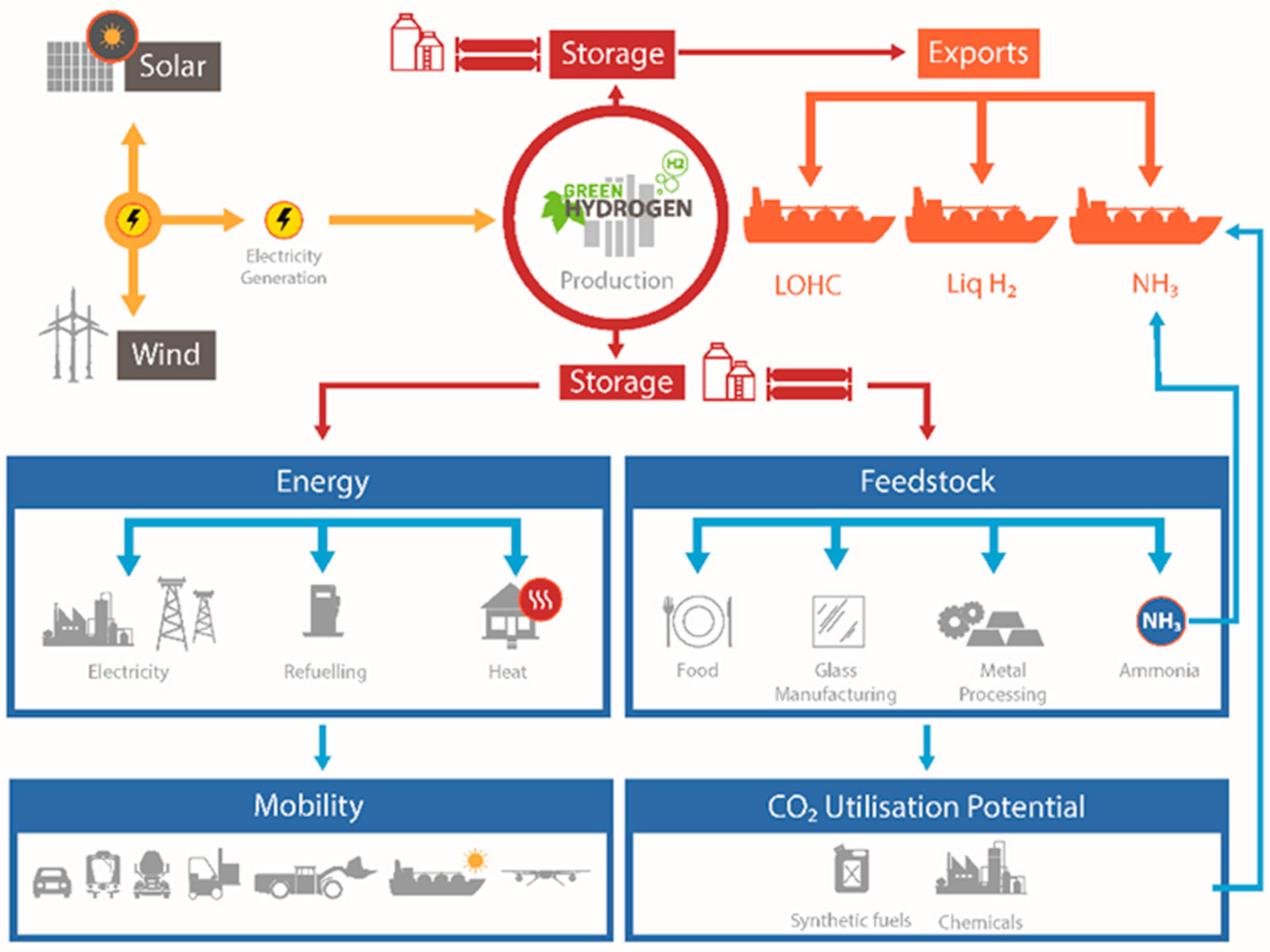
2. Hydrogen as an Energy Carrier

The RES is a natural energy source that, in contrast to fossil fuels, will practically never deplete. However, there are some challenges associated with using RESs, such as seasonal and daily intermittent supply (e.g., periods of low wind speeds and low/no solar radiation). Due to the inconsistency of RESs, significant work has been done on incorporating RES into existing energy networks. More so, mediating the differences in RES supply and the general energy consumption is a major limiting factor, if RESs are incorporated into society [51,52,53,54].
The use of hydrogen can be a key element in solving this problem. Here, hydrogen is considered as a medium to store energy produced by RES in times of excess. When required, the energy associated with hydrogen can be recovered via the following reaction [55]:
H2 + O2 → H2O, ∆H = −285.8 kJ/mol.
This hydrogen conversion is done by various means, e.g., direct or catalytic combustion, or by supplying it to a proton exchange membrane fuel cell (PEMFC). The storage of hydrogen is currently a critical issue and must be solved before establishing economically and technically viable hydrogen-based energy systems [56]. The main drawback of hydrogen, when it needs to be stored, is its low gaseous density (0.09 kg/m3) and high liqueous density (70.9 kg/m3) [57,58]. There are different hydrogen storage approaches that exist (Figure 2): (i) compressed gas; (ii) liquid; (iii) material-based; (iv) metal hydrides; (v) chemical storage [59,60,61,62].
Currently, compressed gas and cryogenic liquid storage are the most mature hydrogen storage methods. The conditions required for these storage technologies, i.e., 350–700 bar for compressed gas and storage temperatures of <−253 °C for liquid storages, confine these technologies. In the case of gaseous hydrogen storage, storage pressures of <350 bar result in an insufficient volumetric density. However, modern compressed hydrogen tanks allow storage pressures of up to 700 bar, which increases hydrogen’s volumetric density to 37 kg/m3 [63].
Alternative hydrogen storage approaches include its chemisorption and physisorption, e.g., ammonia, metal hydrides (chemosorbed by the metal host lattice), metal oxides (thermochemical reduction and oxidation), metal–organic frameworks, carbon-based materials (physisorbed on the surface of the pores), and liquid organic hydrogen carriers (LOHCs) [64,65,66,67,68,69,70,71,72,73,74,75,76,77,78,79,80,81]. In recent years, sodium borohydride (NaBH4) has been considered as a hydrogen storage medium [82,83,84], mainly due to its high hydrogen capacity of 10.8 wt % [85,86,87]. However, the hydrogen release from NaBH4 requires high temperatures [88]. The use of LOHCs has received significant attention in recent years due to its ease of storage and transportation [65,73,89], and several LOHC-based systems have been developed [73,90,91,92,93,94,95,96,97,98]. However, the temperature for hydrogen release is relatively high, e.g., 200–300 °C for the dehydrogenation of perhydro-dibenzyltoluene over Pt/alumina catalysts [99]. Thus, onboard dehydrogenation reactor automobiles would be difficult to operate due to the complexity of the system [63]. Despite the latter, LOHCs are considered the most suitable medium for hydrogen storage and its transportation [65,73].

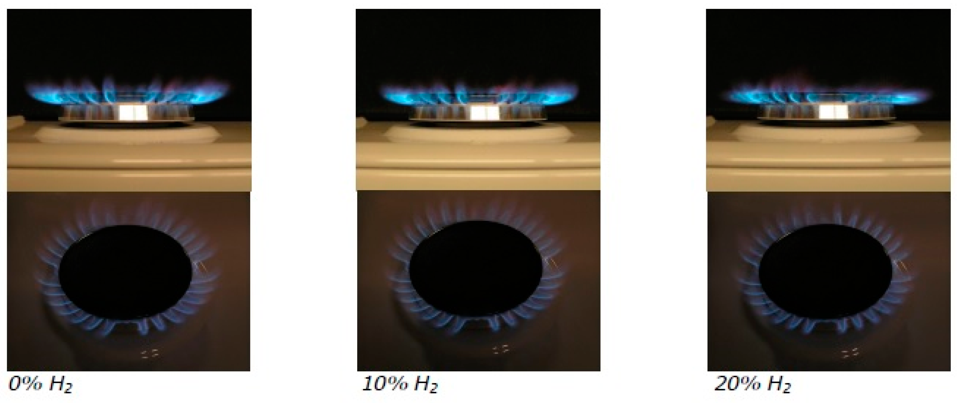
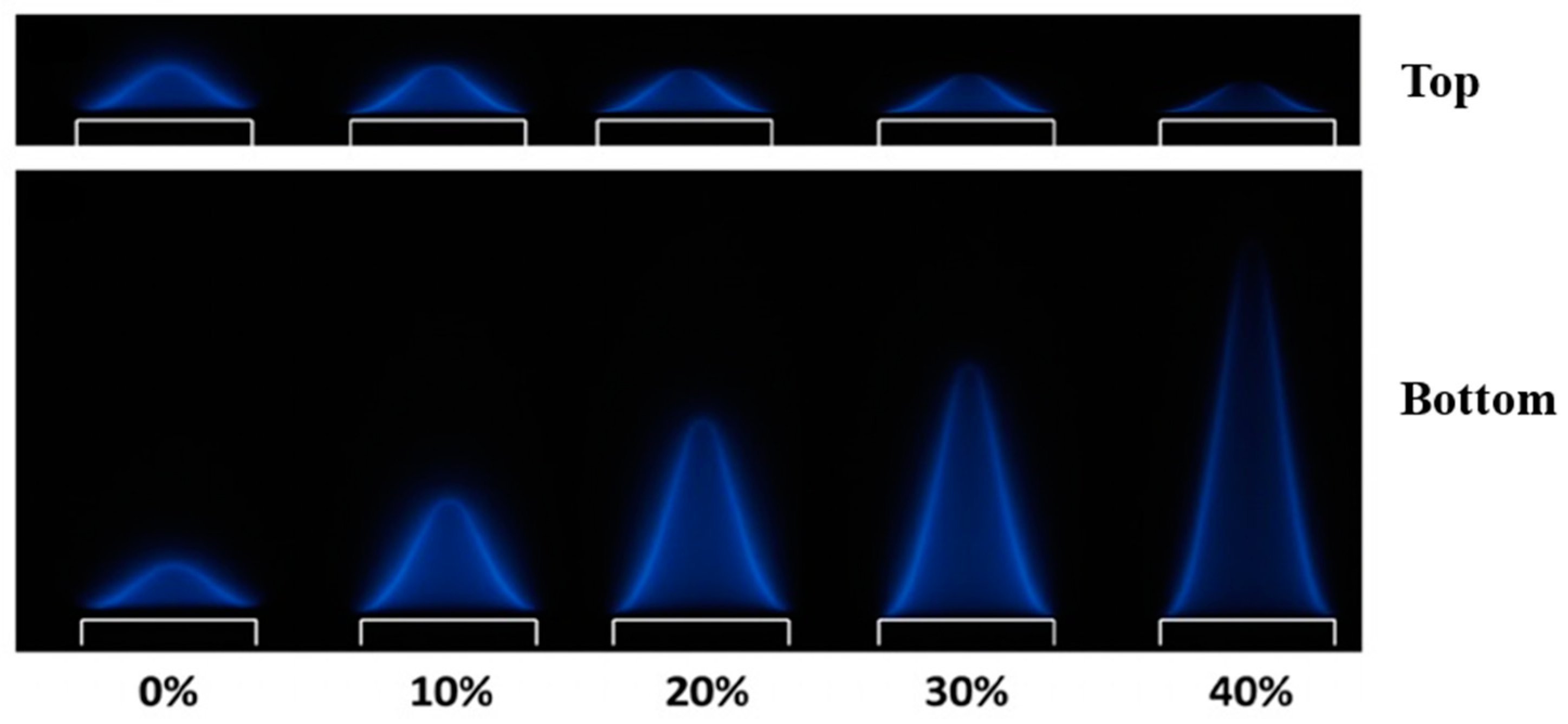
3. Direct Combustion of Hydrogen
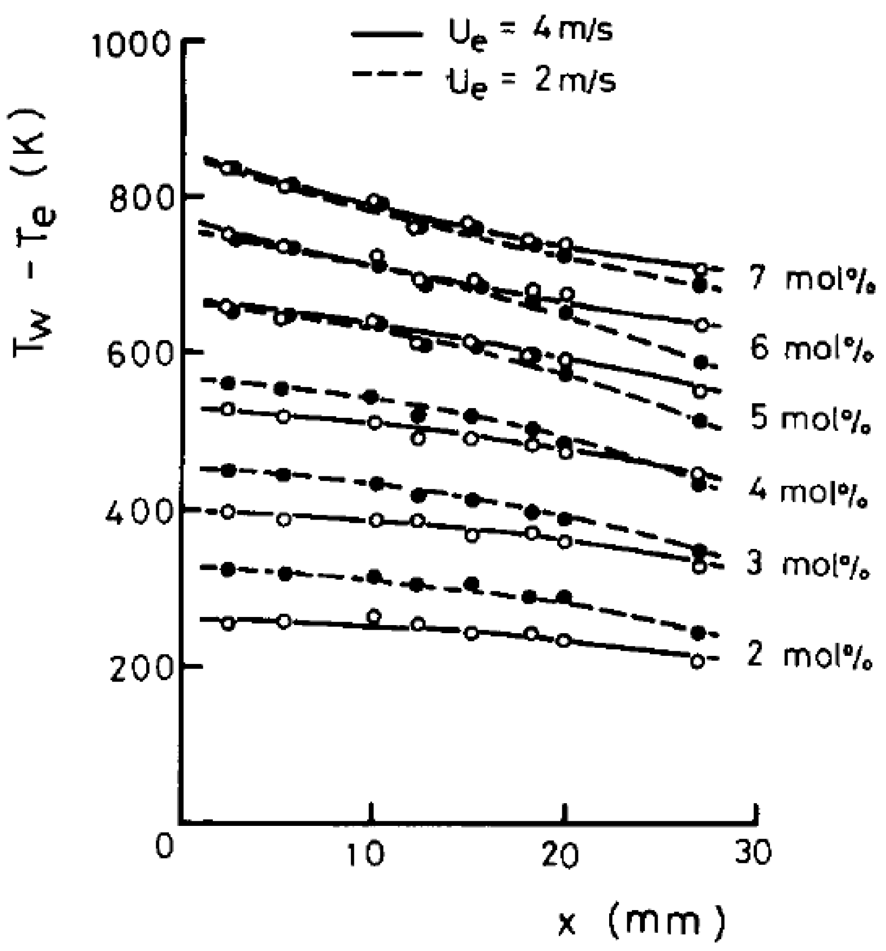
The study of spatial heating and building energy demand has received attention, as the topic of sustainability has become more prominent [100,101,102,103,104]. In Europe, the energy consumption of buildings accounts for 40% of total energy use and 36% of total carbon dioxide emissions in 2010 [105]. In the UK, domestic gas usage contributes to 9% of nationwide CO2 emissions (2007–2009) [37,104]. In an attempt to lower CO2 and NOx emissions, the addition of hydrogen fuel can be an effective solution [106,107].
Hydrogen blending into existing natural gas networks has received significant attention in recent years. For example, the pilot project “Hydrogen injection in natural gas on Island of Ameland in the Netherlands” was successfully demonstrated [40]. The injection of hydrogen up to 20% into the natural gas network was undertaken for four years. The project evaluation showed that no damage to existing gas boilers and cooking appliances occurred during the four years, suggesting that the existing pipeline network and domestic appliances are not a restricting factor for blending hydrogen up to 20%. It was also shown that a 20% hydrogen addition decreased COx emission by approximately 2% [40]. Hydrogen blending does, however, affect combustion characteristics. Figure 3 presents a gas cooker ring fuelled by hydrogen-enriched natural gas to illustrate this.
It can be seen from Figure 3 that with an increase in hydrogen concentration in a natural gas/hydrogen mixture, the combustion flame occurs closer to the gas port. This can, however, be expected, considering the increased flame speed of hydrogen when compared to natural gas [40]. In a study by Nurmukan et al., combustion characteristics, such as the occurrence of blow-offs (high fuel flow velocity that extinguishes the flame) and burning velocities, were examined for biogas/hydrogen mixtures [108]. Figure 4 presents the images of the biogas/hydrogen flames with hydrogen concentrations in the range of 0–40 vol% at the same inlet velocity (top) and the images of the flames at various inlet velocities before blow-off (bottom).
The authors stated that the addition of hydrogen leads to the following changes: more active H radicals, increased initial temperatures of the gas mixture, increased flame speed, and a higher likelihood of blow-off at elevated hydrogen concentrations. More so, most of the combustion occurs at the space close to the burner ports which results in a steep temperature gradient (ΔT) of the flame and a decrease in reaction zone thickness (Figure 4). More so, tip opening occurred with a 40 vol% hydrogen addition. The effect hereof is characterized by two factors: the curvature of the flame tip and the disproportion of molecular diffusion of the components of the mixture. However, the effect is more apparent at higher concentrations of hydrogen [108].
In a study by Di Sarli and Di Benedetto, the laminar burning velocities of hydrogen/methane mixtures have been studied. It was found that the laminar burning velocity increased linearly with an increase in the molar hydrogen content of the fuel mixture [109]. The inclusion of hydrogen in a methane/air fuel mixture also improves the resistance of the flame to strain-induced extinction [110,111]. The latter is due to the above-mentioned increased laminar burning velocity of the hydrogen-enriched fuel, thus enhancing the robustness and stability of the flame.
Notwithstanding complications associated with hydrogen blending to existing gas networks (e.g., increased flame burning velocity and blow-offs), several such projects have been undertaken in recent years. For instance, the GRHYD project on hydrogen injection into a gas grid was carried out in Dunkirk, France in 2017. The hydrogen produced by electrolysis was steeply introduced (6, 13, and 20 vol%) to the gas network and supplied to around 200 houses [41]. The HyDeploy project at Keele University in the UK blended up to 20 vol% of hydrogen into the university’s private gas network (approximately 12,000 residents) [41]. Several projects in Germany blended lower concentrations of hydrogen (up to 5 vol%) to gas lines. For example, one of the first projects was in Frankfurt, where grid electricity was used to power a proton exchange membrane (PEM) water electrolyzer, and the produced hydrogen was injected into the local gas network (up to 2 vol%). In Falkenhagen, hydrogen produced using wind farm and alkaline electrolysis was blended (up to 2 vol%) into the gas grid. Another project in Hassfurt injected hydrogen (up to 5 vol%) into the gas grid, when excess renewable electricity was supplied to a 1.25 MW PEM water electrolyzer [41].
From the results of the above-indicated projects, it may be concluded that European natural gas pipeline networks have the potential to accommodate a fraction of hydrogen blending. These projects demonstrated that up to 20 vol% hydrogen can be added to gas pipelines without modifying the existing infrastructures. A critical considering to be made before increased hydrogen blending (i.e., >20 vol%) to the natural gas network is to ensure the reliable and safe operation of existing domestic gas burners.
Hydrogen has some distinctive properties, which contribute to better performance, such as stability of a burner by suppressing the occurrence of flame blow-off, prevents yellow-tipping (incomplete combustion by lowering the oxygen requirements), and, as previously mentioned, lower GHG and NOx emissions compared to natural gas [104]. However, some undesirable effects, such as flash-backs (an explosion caused by a flame entering the area from which the hydrogen was supplied) and high NOx formation at relatively high hydrogen concentrations, can also be observed [104,112]. Table 1 presents the combustion properties of hydrogen in ambient air [58,112,113].
The minimal ignition energy of hydrogen is 0.02 mJ (within its flammability range), which is an order of magnitude lower than that of methane (0.29 mJ). This property indicated the minute energy required to facilitate hydrogen’s ignition, e.g., a small spark. The combustion velocity of hydrogen is higher than that of conventional fuels (e.g., 2.65–3.25 m/s compared to 0.37–0.45 m/s for methane). Generally, if the combustion velocity is high, there is a risk of flash-backs, whereas a low velocity increases the risk of blow-off [58]. In the case of hydrogen combustion, the high combustion velocity means that the risk of flash-backs is higher than that of blow-offs. Therefore, a proper technical design of the burner is essential, when hydrogen is the intended fuel.
The adiabatic flame temperature of hydrogen is 2045 °C, which is higher than that of methane (1875 °C) and liquefied petroleum gas (LPG, 1970–1980 °C) [112]. However, a higher flame temperature also results in a higher level of NOx emissions. NOx includes NO and NO2; NO generally forms in the post flame region during fuel combustion and is oxidized to NO2 nearly immediately after its formation [114]. N2O formation during hydrogen combustion is negligible and accounts for 1–3% of the global N2O emissions [115].
There are three main paths for NOx formation: thermal, prompt mechanisms, and fuel NOx [116]. Thermal NOx formation occurs, when atmospheric nitrogen oxidizes at flame temperatures higher than 1527 °C [116,117]. Prompt NOx forms, when hydrocarbon fuels react with atmospheric nitrogen. In this mechanism, mainly CH and CH2 species react with molecular nitrogen, leading to the formation of amines or cyano compounds that subsequently react to form NOx. The formation of prompt NOx is dominated at temperatures lower than 1727 °C; for temperatures higher than 1727 °C, most of NOx is formed by thermal mechanisms [116].
The formation mechanism of fuel nitrogen varies with the fuel; for example, natural gas produces mostly thermal NOx, while coal (typically contain 0.5–2.0 wt % of nitrogen) produces mostly fuel NOx [115,116]. A reaction mechanism of fuel NOx involves reactions of the oxidation of hydrogen cyanide (when the fuel nitrogen is bound in an aromatic ring) and ammonia (when fuel nitrogen is in the form of amines) [116]. The formation of fuel NOx is relatively independent of temperature [115]. Due to the lack of nitrogen and carbon in hydrogen fuel, the formation of prompt and fuel NOx is prevented during hydrogen combustion. Nevertheless, the adiabatic flame temperature of hydrogen (i.e., 2045 °C) is significantly higher than the temperature required for thermal NOx formation. Du Toit et al. demonstrated that the combustion of 20 vol% hydrogen/biogas fuel results in a 47.1% reduction in NOx when compared to the combustion of 100% CH4 fuel [118]. Besides the flame temperature, several factors affect thermal NOx formation, including oxygen content in the fuel, combustion temperature, and/or time at high-temperature, high-oxygen environment conditions [115].
Due to the wider flammability range of hydrogen compared to those of other fuels (4.0–75.0 vol% for hydrogen compared to 5.3–15.0 vol% for methane and 1.0–7.6 vol% for gasoline), the combustion temperature of hydrogen can be reduced by varying the equivalence ratio (i.e., fuel/oxidant ration). The injection of water or steam into the combustion zone can also be applied to reduce the combustion temperature; however, this method is usually used for combustion turbines only [115]. Therefore, the formation of thermal NOx during the combustion of hydrogen is found to be well controlled and can be reduced to negligible amounts.
A positive feature of hydrogen is its high diffusivity (0.63 cm2/s for hydrogen compared to 0.2 cm2/s for methane), which helps hydrogen to diffuse to an incombustible concentration within a short time in the event of accidental hydrogen leakage [112].
It may be concluded from this section that direct hydrogen combustion is expected to receive significant attention in the coming years due to its likely application in a hydrogen-energy economy. Hydrogen-enriched fuel offers an intermediate solution towards a hydrogen-enriched gas network to reduce domestic GHG and NOx emissions. It has been demonstrated that hydrogen can be blended in a range of 2–20 vol% into existing natural gas networks, without the need for an expensive overhaul of existing gas appliances [41]. A hydrogen addition of 20 vol% afforded a decrease in COx emissions by 2%. Hydrogen enrichment does, however, reduce the sustainability of the combustion flame due to the blow-off effect. The effect usually occurs, when the burner is fed with an insufficiently fuel-rich mixture [119]. More so, the combustion velocity increases due to hydrogen’s high burning velocity. Therefore, the direct combustion of hydrogen still suffers from some technical issues and requires further detailed investigation.

4. CHC

The incentive to employ CHC rather than direct hydrogen combustion is ascribed to further minimize GHG and NOx emissions, combust lean gas mixtures (i.e., mixture with a stoichiometrically lower hydrogen-to-air ratio) and increase the combustion stability [120]. Initially, catalytic combustion was developed for natural gas. Its commercial application (e.g., burners and heaters) has remained limited due to the main reasons of the high price for catalytic devices (compared to their noncatalytic counterparts) and various technical reasons (e.g., low catalyst activity and durability). Likely, the application of catalytic devices will only receive significant interest, when environmental policies dictate lower harmful exhaust limits [120]. For example, the oil crisis in the mid-1970s generated interest in hydrogen energy, and different catalytic combustion applications appeared after 1974, as well as international conferences (e.g., World Hydrogen Energy Conferences (WHECs)), organizations (e.g., the American Hydrogen Association), periodicals (e.g., the International Journal of Hydrogen Energy), books, etc. [120,121]. To date, public pressure is rising to limit global warming that renews interest in hydrogen and imposes further investigation in CHC applications [39,122].
The main features of any device used for CHC are the catalyst used and the burner design. The catalyst is of importance here, which consists of two equally important parts, i.e., the reactive metal and the support. In cases where the CHC catalyst has sufficient catalytic activity, the CHC reaction proceeds spontaneously under standard ambient conditions. For instance, on the surface of nano-sized Pt particles, the CHC reaction can be initiated at sub-zero temperatures, whereas gaseous hydrogen combustion typically initiates at 585 °C in the absence of a catalyst [120,123]. More so, hydrogen is relatively sensitive to catalytic combustion as, for instance, the catalytic combustion of methane proceeds at 275–450 °C [58,124,125,126,127].
Catalysts containing dispersed nano-sized Pt particles are typically highly active and are used in various hydrogen-based technologies, e.g., electrochemical hydrogen compression, PEMFCs, PEM water electrolysis, and LOHC dehydrogenation [73,128,129,130,131,132,133,134,135,136,137,138,139,140]. In general, reducing reactive metal loadings has been a primary research focus, and catalyst development (e.g., catalyst stability and durability) has received relatively limited attention.
Catalyst support materials have a significant effect on the catalyst stability, especially when the catalyst is intended for high-temperature applications. For CHC, support materials with high thermal resistance are considered. However, in many cases, such supports have low thermal conductivity, which results in the formation of hotspots. Hotspots are defined as areas where the localized surface temperature is higher than the average surface temperature over the catalyst surface [130,141]. Safe and prolonged CHC is perplexed by the formation of hotspots, if the catalyst support material is unable to dissipate reaction heat [130,141,142,143,144,145]. The appearance of hotspots may lead to a nonuniform catalyst degradation, as well as hydrogen ignition if its autoignition temperature is exceeded [130,141,142,146].
To avoid hotspot formation, numerous studies have been performed by varying hydrogen/oxidizer ratios and by employing diffusive or premixed combustion [141,143,144,147,148]. For example, Haruta et al. compared the thermal distribution of a Ni foam and a ceramic honeycomb catalyst supports during CHC. It was found that the ceramic support has better thermal distribution compared to the Ni foam support [143]. Kozhukhova et al. demonstrated that the thermal conductivity of the Al/anodized aluminium oxide (AAO) support depends on the quality of the reactive metal impregnation procedure. The authors showed that a uniform Pt distribution results in a uniform thermal distribution throughout the support; the ΔT was 23 °C. It was shown that even in the case of hotspots formation the ignition of hydrogen is highly unlikely due to the high thermal conductivity of the AAO support, which is closely adhered to a metallic Al core. Norton et al. utilized thermal spreaders (a copper thermal spreader for low thermal resistance and a stainless-steel thermal spreader for intermediate resistance) to achieve the efficient thermal uniformity of a microburner [144,148]. To guide future research on the development of materials and devices for the catalytic combustion of hydrogen, current and previous works are summarized in the following sections.

4.1. Materials for CHC

The first mention of a flameless catalytic hydrogen burner refers to 1974 by Sharer and Pangborn [149,150]. Information regarding the catalyst material and experimental conditions used by Sharer and Pangborn was not reported in detail. The main impediment for further investigation was the limited availability of effective catalysts at a reasonable price. Hereafter, CHC was investigated over a flat Pt plate by Mori et al. in 1977 [151]. The authors demonstrated that the CHC of a hydrogen/air mixture with a concentration of hydrogen in the range of 2–7 mol% occurred at temperatures below 827 °C. However, it is worth noting that the Pt plate had to be activated before the test by heating in a 8 mol% hydrogen–air mixture at 527 °C. From the experimental results, the authors found that the Pt plate catalyst showed a nonuniform active site distribution and the additional etching treatment of the Pt plate did not yield a uniform catalytic surface. Although the Pt plate did not show uniform catalytic activity, no significant ΔT was observed due to the high thermal conductivity of Pt that varied in a range of 0.70–0.74 W/cm∙K [152,153,154]. Figure 5 presents the surface temperature distribution measured in the study, where the x-axis express the distance x from the leading edge (the area closest to the hydrogen/airflow source) and the y-axis expresses the difference between the temperature of the gas and the surface temperature (Tw – Te) [151].
Further investigations of CHC over Pt-coated thin quartz plates were performed by Schefer et al. in 1980 [142,155]. CHC was investigated for lean hydrogen/air mixtures (equivalence ratios: 0.05–0.3) over a pre-heated catalytic plate. The results of the study can be summarized as follows: (i) little or no CHC occurred at an equivalence ratio of <0.1; (ii) significant CHC occurred at hydrogen/air equivalence ratios of >0.15 and plate surface temperatures of >197 °C; (iii) the autoignition of hydrogen occurred at the highest temperatures (897–997 °C) and an equivalence ratio of >0.25 [142].
In the study by Haruta and Sano in 1981, the authors examined the catalytic activity for the CHC of different catalysts, using a combustion temperature for 50% hydrogen conversion (T1/2) as an evaluation parameter [156]. It was found that oxides of metals such as Co, Ni, Mn, and Cu were active for CHC with T1/2 of approximately 150 °C (required pre-heating for the combustion initiation, the authors did not specify the exact initiation temperature). Meanwhile, it has been found that Pt and Pd-based catalysts were able to initiate CHC even at a temperature of <0 °C (with T1/2 below 50 °C). The results obtained by the authors for several catalysts were summarized and presented in Figure 6.
In another study by Haruta et al. in 1982, the performance of different catalysts was investigated for a catalytic hydrogen combustor [143]. Four types of catalysts were examined: a ceramic honeycomb impregnated with Pt, two Ni metal foams with different pore sizes (11–15 and 35–44 cells/inch) coated with Pd powder, and a ceramic foam coated with Co–Mn–Ag oxide powder. The authors found the the Pd-coated Ni foam with a bigger pore size as the catalyst led to the highest combustion efficiency (hydrogen conversion of >90%), while a nonuniform surface temperature distribution (ΔT of 220 °C) was observed during the reaction (Figure 7) [143]. The Co–Mn–Ag-coated ceramic foam catalyst was found to be suitable for CHC, although it required pre-heating (approximately 50 °C) for the initiation of the combustion. Besides, it was stated that the catalyst structure has an appreciable impact on the surface temperature distribution; the ceramic supports are advantageous over the metal support (i.e., Ni), as they provided a uniform temperature distribution [143].
A similar observation was made in a study by Mercea et al. in 1982 [157]. Two types of catalysts were investigated: Pt-coated fibrous plate and Pt-coated SiO2/Al2O3 ceramic. The authors found that the ceramic support distributed heat more uniformly compared to the fibrous support, while the combustion efficiency was lower (approximately 1.0 vs. <0.95 for the fibrous and ceramic supports, respectively). The observed differences in efficiency were ascribed to the more rapid diffusion of oxygen to the fibrous catalytic surface [157].
In the study by Inui et al., a three-component composite catalyst Ni–Ce2O3–Pt supported on a ceramic fiber plate (Fiberfrax) was explored and evaluated for CHC. Oxygen conversion served as an evaluation parameter for CHC reaction [158]. The authors found no activity for single- and two-component Ni and/or Ce2O3 catalysts, while two-component catalysts based on Pt and Ni or Ce2O3 showed high activity (up to 99.1% oxygen conversion) [158]. It was also found that the three-component (Ni, Ce2O3, and Pt) catalyst achieved a high catalytic activity (100% oxygen conversion). The synergistic effect of the reactive metal combination had a beneficial effect on the catalyst activity.
Further, a Ni oxide plate catalyst was studied for CHC in a study by Fakheri et al. [159]. The temperature distribution throughout a catalyst plate was found to be uniform, but the catalyst showed no or very little activity at temperatures of <410 °C [159]. It is also worth noting that the Ni oxide catalyst had to be activated before each test by heating in oxygen at 400 °C for 1 h and then reduced in hydrogen at 400 °C for 1 h.
From 1900 to 1999, the literature review reveals mainly the fundamental studies on hydrogen–oxygen reaction mechanisms over Pt catalysts, surface kinetic, and numerical studies [160,161,162,163,164,165]. Later, the low-temperature (<250 °C) combustion of a lean hydrogen/air mixture over a Pd-based catalyst was studied using a microreactor by Kramer et al. [166]. In the study, γ-Al2O3 washcoat was used as a support material. The authors found a hydrogen conversion of <40% at inlet temperatures below 125 °C and a near-complete hydrogen conversion at an inlet temperature of 200 °C. The authors further showed a Pd catalyst pre-reduced in an H2/N2 atmosphere at 400 °C had a hydrogen conversion of 85% at an inlet temperature of 100 °C. Moreover, it was found that the presence of water vapor reduced the conversion at lower temperatures (<125 °C) [166].
A numerical model of a porous Pd/PdOx-washcoated catalyst was created to explore the effect of the intra-phase diffusion of a channel flow reactor during low-temperature hydrogen combustion [167]. The thickness of the washcoat varied between 10 to 80 µm. The results indicated that the hydrogen conversion did not exceed 75% for all tests. More so, the authors estimated the catalyst effectiveness, which is defined as the ratio of the integrated reaction rate throughout the nonuniform porous washcoat layer to the idealized reaction rate if the layer were at the same conditions as its outer surface. The decrease in the effectiveness from 0.6 to 0.4 was observed with an increase in the washcoat thickness from 40 to 80 µm. A reduction ineffectiveness from the ideal value of 1.0 was ascribed to the intra-phase diffusion in the pores of the washcoat layer. It was shown that the thicker washcoat results in a lower phase fraction of hydrogen in the washcoat that, in turn, cause a reduction in surface activity for CHC reaction [167].
Choi et al. studied CHC using a catalytic combustor (10 mm × 10 mm × 1.5 mm) [168]. The authors used a porous firebrick material (Isolite B5) as the support material for the Pt catalyst. Hydrogen conversion and temperature distribution throughout the catalyst surface were determined for the catalysts with different Pt loadings (0.4–3.73 wt %). Hydrogen conversion was found to be >95%, independently on Pt loading, suggesting the high catalytic activity of the Pt/Isolite B5 catalyst [168]. It was also found that water, which is a product of CHC, decreased catalytic activity. It was, however, determined that a larger hydrogen flow rate and a lower equivalence ratio may suppress water formation. Although the Pt/Isolite B5 catalyst demonstrated high performance toward the CHC reaction, a significant surface ΔT (up to 570 °C) was observed for all experimental conditions (Figure 8) [168].
The pre-mixed hydrogen/air flow entered the combustor chamber at the bottom and exhausted at the top. Figure 8a shows that, at the beginning of the test (10–30 s), the drops of water started appearing at the bottom of the catalyst. After 80 s of the test, the water drops started to move towards the top of the catalyst and later evaporated due to continuous heat generation. It was also found that the higher the volume flow rate, the larger heat generation occurred during CHC that accelerated the evaporation of water in the initial stage of the reaction. The same observation was made by decreasing the air/hydrogen equivalence ratio. The authors found that a larger active surface area can be formed when a lean hydrogen/air mixture is supplied, resulting in faster water evaporation [168].
In another study by Zhou et al., the performance of micro-combustors made of quartz glass, alumina ceramic, and copper was tested [169]. The authors found a uniform temperature distribution for the copper combustor while the alumina and quartz combustors showed the formation of hotspots, although all combustors had high stability [169].
Zhang et al. developed a mesoporous ceramic-coated monolithic Pt-based catalyst (Pt/Ce0.6Zr0.4O2/MgAl2O4/cordierite) for CHC [170]. The catalyst showed excellent catalytic activity (hydrogen conversion: >99%) and could quickly initiate the combustion reaction (less than 150 s) at temperatures as low as −10 °C. A hydrogen conversion of >95% was obtained for hydrogen concentrations of 3 and 4 vol%. Hydrogen conversion decreased to <20%, when the hydrogen concentration was between 1 and 2 vol% [170]. Figure 9 presents the SEM and TEM images of the MgAl2O4 coating on the cordierite ceramic prepared in the study.
Recently, a Pt-based SiC foam catalyst was explored for CHC for a lean 1 vol% hydrogen/air mixture in a study by Fernandez et al. [171]. The catalyst initiated the CHC reaction at room temperature, suggesting the high catalytic activity of the Pt/SiC foam catalyst. A hydrogen conversion of 100% was achieved during CHC. Later, the Pt/SiC foam disk catalyst was applied for the development of a catalytic burner suitable for domestic kitchen applications (discussed in Section 4.2) [147].
In a study by du Preez et al., a stainless-steel mesh (SSM) was used as catalyst support for Pt-assisted CHC [129]. The authors found that the SSM support did not stabilize Pt during CHC that resulted in Pt aggregation. The latter observation was ascribed to the Pt mobility on the metallic SSM support at high temperatures. However, the authors showed that the functionalization of the SSM support through calcination at temperatures of 500–1000 °C for 2 h could prevent Pt aggregation during CHC. Figure 10a,c presents SEM micrographs of Pt/SSM catalysts prepared using the as-received SSM support and the SSM support calcined at 1000 °C after hydrogen exposure, respectively. Figure 10b presents an SEM image of the SSM support calcined at 1000 °C. The Pt/SSM catalyst reached combustion temperatures of 420–520 °C; however, the catalyst had to be pre-heated to 40 °C, before the initiation of CHC reaction occurred [129].
In another study by du Preez et al., Ti mesh was evaluated as a catalyst support for CHC. The same observation was found by the authors: only the additional calcination of the Ti mesh at temperatures of 900 and 1200 °C could prevent Pt aggregation during CHC. Combustion temperatures of >477 °C were achieved by a Pt/Ti mesh catalyst after being pre-heated to 70 °C [128]. Figure 11 shows the SEM micrographs of the Ti mesh support calcined at different temperatures (Figure 11a–c) and those of the Pt/Ti mesh catalyst after 5 h continuous high-temperature (480–530 °C) hydrogen combustion (Figure 11d–f).
It was demonstrated that the Ti mesh support calcined at 600 °C did not stabilize Pt and severe aggregation of Pt occurred during CHC; the size of Pt particles ranged between 241.3 and 1280.9 nm. The calcination at 900 and 1200 °C showed good Pt stabilization due to the presence of a functionalized oxide layer on the Ti surface. The size of Pt particles was 180.7 nm after CHC for the catalysts prepared using the Ti mesh support calcined at 900 and 1200 °C.
In a study by Kozhukhova et al., an Al/AAO material was employed as a Pt catalyst support. Figure 12 presents an SEM micrograph of the AAO support and TEM micrographs of the Pt/AAO catalyst. Pt/AAO catalyst was evaluated for CHC; a stable hydrogen combustion temperature of 338 °C was maintained for 530 h of continuous CHC [130].
Figure 12 shows the images of the Pt/AAO catalyst before exposure to CHC. As can be seen, the AAO layer represented a hexagonally organized array of pores; Pt nanoparticles formed within the AAO channels. The wet impregnation method provided the formation of highly dispersed Pt particles at a nanometer size (4.7 nm) after reduction. The latter fact afforded the high catalytic activity of the Pt/AAO catalyst (low initiation temperature of 24 °C; quick start-up of 100 s). More so, the stable combustion temperature was maintained for 530 h of CHC that indicated no Pt aggregation occurred [130].
The latter study demonstrated the importance of the Al core in the Pt/AAO catalyst for the stabilization of Pt during CHC [141]. The Pt/AAO catalysts were subjected to a hydrogen/air mixture in the recombiner section testing station to evaluate the thermal distribution of the catalysts. It was demonstrated that, due to the Al core present in the Pt/AAO catalyst, the thermal displacement occurred quickly and uniformly that prevented the hotspots formation. The ΔT of 23 °C over 70 mm of the catalyst surface was obtained. In turn, the Pt stability was enhanced during CHC [141]. Figure 13 shows the TEM micrographs of the Pt/AAO catalyst before and after 530 h of continuous CHC.
The average Pt particle size before CHC was 3.0 nm. Figure 13b demonstrates that some Pt aggregation occurred after 530 h of CHC (the arrows in Figure 13b show Pt aggregates), although the effect of that on the combustion temperature was not evident. Therefore, the authors assumed that Pt aggregation was insignificant and did not affect the catalytic activity of the Pt/AAO catalysts [141].
In a summary, the catalytic system consists of reactive metal and catalyst supports; the choice of support material, however, plays a critical role in the development of a high-performance catalyst. In general, the catalyst for CHC purposes should satisfy the next following criteria: (i) the catalyst should initiate the combustion reaction of hydrogen or a hydrogen/air mixture at the lowest possible temperatures (initiation temperature); (ii) the catalytic activity of the catalyst must afford near-complete or complete hydrogen combustion (high hydrogen conversion); (iii) the support should have a high surface area, a high thermal and corrosion resistance, and a high working temperature; (iv) the support should prevent catalyst aggregation during the CHC reaction; (v) the catalytic system should be able to maintain high catalytic activity during prolonged high-temperature CHC reactions; (vi) the catalytic system should provide a uniform heat distribution throughout the entire catalytic surface preventing hotspot and flame formation; and (vii) the fabrication of the catalyst support should be economically viable, i.e., low cost.
The present review has pointed out that although numerous studies on identifying suitable catalysts for CHC purposes have been performed, the majority of catalysts do not fully meet the criteria as outlined in the above text. Nonetheless, the summary of the existing catalysts for CHC may be found useful, when a high-performance catalyst is to be developed. Table 2 presents a summary of the existing catalysts used for CHC and short comments regarding the catalysts’ limitations and performances for CHC purposes.
As can be seen from the review presented in Section 4.1 and Table 2, the investigations on CHC have been mainly done using Pt and Pd as reactive metals. Pt and Pd are most active for CHC among other metals and metal oxides providing the highest hydrogen conversion and high resistance to chemical attack (e.g., insensitive to sulfur poisoning). Additionally, these catalysts are easily prepared in a highly dispersed form on most supports; therefore, only small amounts (0.1–0.5 wt %) are usually required for preparing catalysts with high activity. However, several studies have revealed that when combining Pt and some metal and/or metal oxides, the high activity in hydrogen conversion can be reached. Metal oxide catalysts typically show lower catalytic efficiency and require higher initiation temperatures, although under specific experimental conditions they can show higher efficiency comparable to Pt and Pd. A persisting issue is that Pt and/or Pd as a catalyst can result in the occurrence of aggregation during high-temperature combustion (>500 °C), especially in the presence of water [173]. However, it was shown that the water release can be suppressed by the higher rate of hydrogen flow and, therefore, the aggregation limit can be extended. More so, du Preez et al. suggested that formed water vapor has a short residence time on the surface of a Pt/SSM catalyst and is rapidly displaced from the surface of the SSM support by natural convection caused by reaction heat. However, in this case, the authors mainly referred to the degradation of the SSM support caused by exposure to water vapor and did not refer to Pt aggregation [129].
From Table 2, it can be seen that ceramic supports are the most widely used for CHC reactions. This may be ascribed to their potential to limit catalyst aggregation and, in some cases, provide a relatively uniform thermal distribution throughout the catalyst surface. Of these ceramics, Al2O3 and TiO2 are widely applied. Al2O3 has a relatively low bond energy with Pt compare to TiO2, suggesting that catalyst aggregation is likely to occur [174]. TiO2, on the other hand, is well suited for CHC but is considerably more expensive than Al2O3. Nagai et al. showed that a mixed Ce–Zr–Y (CZY) oxide affords a Pt/CZY oxide catalyst with excellent Pt distribution and stability, i.e., Pt particle size of about 1 nm and Pt stability when calcined at 800 °C for 5 h (aging treatment) [174]. Therefore, it may be concluded that although numerous catalyst supports have been identified, significant research effort is still required to explore more suitable supports. More so, the relevant support fabrication procedures should be identified, keeping in mind that economic feasibility is a primary determining factor of identifying a process. If any form of production upscaling is to be considered, it has to be executable at a low cost.

4.2. Devices for CHC

The areas where devices using CHC may play a role include residential applications (e.g., cookers, radiant heaters, and boilers), engines (e.g., turbines), industrial (e.g., burners, heaters, and engines), and safety (e.g., passive autocatalytic recombiners) applications. Although the commercial application of catalytic devices is relatively limited, many studies are under the development stage and several prototypes have been designed and tested up to date.
Justi and Selbah applied the CHC reaction in secondary galvanic batteries that produce hydrogen during battery charging. The catalyst consisted of Pd on a hydrophobic support. Using the recombination catalyst, a heating installation using CHC was developed [58]. Mercea et al. examined the CHC over a Pt-based catalyst for spatial heating [175]. A heater was placed in a room with a total area of 7.5 m2 and continually operated for 30.5 h; the room temperature increased from 13.5 to 17.5 °C and remained constant for 8 h. At the end of the test, the hydrogen concentration was determined to be low (0.00015%), indicating near-complete hydrogen combustion [175].
Haruta and Sano carried out fundamental investigations on the identification of the most suitable catalysts for CHC, advantages of hydrogen fuel, and catalytic burner design [146,176]. Two catalytic burners with dissimilar hydrogen inlets were fabricated: (i) hydrogen was introduced at the bottom; (ii) hydrogen was distributed uniformly (Figure 14). More so, two catalysts, i.e., Pt/Ni foam and Co-Mn-Ag oxide, were evaluated in the burners catalysts [146].
The authors observed a large ΔT (up to 514 °C) across the catalyst surface when a bottom hydrogen-distributed burner was utilized. Hotspots formed due to the nonuniform temperature distribution ignited hydrogen at the bottom of the catalyst, which resulted in unwanted flame formation. The uniformly distributed hydrogen burner had a relatively uniform temperature distribution (ΔT was 147 °C for the Co–Mn–Ag catalyst and 200 °C for the Pt/Ni foam catalyst). Combustion efficiencies of >64.7% were obtained for all tests for both burners; however, a combustion efficiency of >96% was obtained at an operating heat input of 1.0 kcal/cm2/h [146].
A prototype of a hydrogen flame-assisted catalytic burner was featured in the 1975 Homestead project of Roger Billings. This project consisted of a two-story residence that was heated using hydrogen, along with hydrogen-run kitchen appliances, fireplaces, outdoor grills, automobiles, and farm tractors [120,177]. A thick stainless-steel wool mat was used as a catalyst; this mat surrounded the burner ports and inhibited the mixing of air and hydrogen to create a stable hydrogen-rich zone around the burner head [120]. Further investigations were focused on the design of catalytic burners and heaters that utilized natural gas as a fuel. However, those attempts were commercially unsuccessful due to the lower durability of the catalyst and the lower inertia (response time of the burner temperature to change in fuel flow) of the burner assembly compared to those of the open flame burners. Nevertheless, developed catalytic devices still can be used to assist in the design of burners and heaters for hydrogen and hydrogen-enriched fuel. For example, Pyle et al. in 1991 examined a commercially available catalytic space heater (Platinum CAT intended for propane and natural gas fuels) for CHC [178]. However, there was no commercial follow-up because of the absence of a sufficient market [120].
The application of CHC for a hydrogen storage system was demonstrated in a study by Johnson and Kanouff in 2012 (Figure 15). A heater based on a Pd/carbon powder catalyst was fabricated as part of the development of a metal hydride hydrogen storage system. The heater operated by CHC used hydrogen from the storage to produce heat required for the hydrogen delivery. Figure 15b shows a process flow diagram for the catalytic heater; hydrogen from the storage tank is mixed with air and injected into a reactor to heat the metal hydride. Up to 30 kW of heat at the flow of a 10 vol% hydrogen/air mixture can be produced. The authors showed that 75% of hydrogen was converted to heat [179].
A prototype of a catalytic hydrogen cooker/stove was developed by Vogt et al. and presented at the European Fuel Cell Forum in 2011. Highly porous SiC ceramics coated with Pt was used as a catalyst for a novel catalytic burner. By supplying the catalytic cooker with hydrogen and air separately, the safe operation of the cooker was achieved. Hydrogen was supplied below the porous Pt/SiC catalyst, and the air was supplied to the top through the nozzles of steel tubes (Figure 16a). The gases then mixed on the catalytic surface, where the CHC reaction occurred. An efficiency of up to 70% as well as the uniform temperature distribution (Figure 16b) was achieved during the operation [180]. Figure 16c shows the Pt/SiC disk used in the catalytic burner.
Further study by the authors was focused on the improvement of the burner design. The stove consisted of four porous Pt/SiC disks arranged in layers and installed in a round stainless-steel casing (Figure 17). Each Pt/SiC disk served as follows: (i) a diffuser SiC disk 1 (porosity of 100 pores per inch (ppi)) served for the initial uniform hydrogen distribution; (ii) a Pt/SiC (80 ppi) disk 2 served as a primary combustion disk; (iii) a diffuser SiC disk 3 (40 ppi) served to improve hydrogen and air distribution; and (iv) a Pt/SiC disk 4 (60 ppi) served as a combustion disk. The air was supplied from the tubes above the combustion disk 2 perpendicular to the hydrogen flow preventing flash-back due to the lack of oxygen below the disk. The results showed that only traces of harmful NOx (<9.5 ppmv) can be obtained at operating temperatures below 800 °C. However, the authors stated that improved catalytic behavior and better thermal conductivity can be achieved [147]. More so, SiC is a relatively expensive material, and although it can be produced using materials considered as waste in certain industries [181], its fabrication requires significant energy input.
It may be concluded from this section that only a few catalytic devices for CHC were developed, although they show promising perspectives as a replacement of conventional flame burners. It was demonstrated that only traces of harmful exhausts can be obtained during the operation of the catalytic hydrogen-fueled burner. Lastly, limited CHC-based devices have been developed and tested for task-specific applications. It is therefore proposed that, if hydrogen is to be considered as a fuel source, domestic and industrial applications should be expanded. More so, the potential of hydrogen as an indoor fuel is relatively unexplored and requires further investigation.

5. CHC for Hydrogen Safety Purposes

An important commercial application of CHC is found in nuclear power plant (NPP) applications. In the case of a severe accident, hydrogen can be produced unintentionally due to the reaction of the zirconium cladding of the fuel rods with steam and by over-heated reactor fuel. Accidentally released hydrogen may reach an explosive concentration (i.e., 4–75 vol%) within the reactor core and, if ignited, can cause damage to structures and equipment and loss of life in NPPs. To mitigate the latter risk, passive autocatalytic recombiners (PARs) can be installed. PARs are safety devices that allow hydrogen removal through CHC reaction from the catalytic surface. A generalized operation of a PAR is presented in Figure 18, showing the hydrogen-containing airflow through the PAR.
The PAR represents a rectangular box with catalytic sections inside. The recombiners function without any external power source and come into action spontaneously when hydrogen is introduced. The CHC reaction starts on the catalytic surface and generates water vapor and exothermic reaction heat according to reaction 1. Reaction heat causes natural convection within the PAR by forcing hydrogen-depleted air out of the PAR and allowing hydrogen-containing air to enter at the bottom. The hydrogen removal usually starts at a non-flammable hydrogen concentration (1–2 vol%), thereby preventing the formation of explosive mixtures with the air [58].
Generally, PARs are mounted in many power plants around the world. There are several PAR manufacturers worldwide: Siemens and NIS (Alzenau, Germany), Atomic Energy of Canada Ltd. (AECL, Chalk River, ON, Canada), Electrowatt Engineering Ltd. (Zurich, Switzerland), AREVA (Courbevoie, France), and ISPC Russian Energy Technologies (RET, Moscow, Russia). The main catalyst materials used in PAR applications may be divided into four groups: (i) cartridges filled with ceramic spherical Pd-coated pellets, (ii) a thin stainless-steel plate wash coated with a γ-Al2O3 layer that supports a noble metal (plate-type recombiners), (iii) metallic catalysts (metallic plate coated with catalyst powder without an intermediate ceramic coating), and (iv) ceramic rods coated with a noble metal. Some of the catalysts are presented in Figure 19.
The first type of catalyst (a prototype PAR developed by the NIS) was investigated in a study by Blanchat and Malliakos in 1999 (Figure 19a). The catalytic section contained one row of 44 catalytic cartridges. The results showed that CHC was initiated after approximately 10 min of hydrogen exposure (1–6 vol% of hydrogen in the air). The reaction was initiated in a hot and steamy atmosphere (102 °C and 50 mol% water vapor) [183].
Reinecke et al. studied the second plate-type recombiner section (Siemens type) [184]. Figure 19b,c presents a schematic and a photograph of a plate-type catalyst recombiner section. The catalyst represented stainless-steel plates coated with a Pt/washcoat arranged in parallel with the gas mixture flow. The authors determined a fast self-start characteristic (the surface temperature of 100 °C was achieved in 5 min), while a ΔT of approximately 200 °C throughout the catalyst surface was obtained. It was also mentioned that the plate-type catalysts for PARs can lead to the unintended ignition of hydrogen due to the overall overheating of the catalyst and the nonuniform temperature distribution.
The third catalyst type was utilized in the KATAREK facility developed by Electrowatt Engineering Ltd. The catalyst represents a full metallic plate without an intermediate ceramic coating obtained by the direct coating of a catalyst powder (Pd 95 wt %, Ni 4 wt %, and Cu 1 wt %) by a high-temperature injection (plasma spraying) [187].
The fourth type of catalyst section was developed by ISPK RET; the catalyst section represents a metallic frame with rod-shaped catalytic elements inside and is presented in Figure 19d. A similar catalyst section was tested in a study by Malakhov et al. in 2020; the catalyst manufacturer was not specified. The authors found a ΔT of 341.2 °C over a tubular ceramic Pt/Al2O3 washcoat catalyst [131].
Furthermore, PARs are also considered by the mining industry as an accident risk mitigation system. It is widely recognized that hydrogen-fuelled trucks are considered as a suitable replacement for diesel-powered vehicles in underground mines. Such a replacement will result in a cleaner atmosphere for underground workers, decreasing the number of harmful exhausts. However, the use of hydrogen in confined spaces is accompanied by the risk of accidental hydrogen release and the formation of explosive mixtures with the air. Detailed research on a hydrogen leak in a semi-closed space (such as in underground mining conditions) was carried out by Malakhov et al. [188]. The experiment was carried out in the HySA mining platform (HySA Infrastructure, Potchefstroom, South Africa) test facility for green mining (Figure 20). The test was conducted under different hydrogen release pressures and leak orifice sizes, and the results obtained were compared the results stimulated with computational fluid dynamics (CFD). The authors found that CFD simulations can be helpful in the development of mitigation strategies for hydrogen safety issues in mining [188].
In another study by the authors, detailed research on the thermal distribution of a catalytic unit in a PAR was carried out. The authors showed that the ability of the catalyst to distribute heat is a key when the PAR is to be installed in confined spaces. The performance of the PAR was evaluated for inputs of hydrogen concentrations in a range 2–5 vol%. In addition, the experimental results were compared with CFD simulated results, and they were in good agreement [131]. Therefore, PARs will likely play a key role in underground mining and NPPs’ accident mitigation in the future.

6. Future Research

CHC has been the subject of numerous scientific investigations, but relatively few have been concerned with the design of domestic burners and heaters. The present review of CHC materials and technologies has pointed out the absence of commercial hydrogen cooking and heating devices. The key obstacle to CHC technologies was identified as the lack of durable and high-activity catalysts.
Therefore, further research and development are required. For example, the catalyst activity (hydrogen conversion; self-start characteristics) and durability may be further enhanced. In addition, the cost of the catalyst can be reduced without diminishing catalytic activity. The modification of supports and the optimization of the catalyst preparation method might be positive approaches for future research. If the design of a catalytic burner is considered for further investigations, the specific features and issues of CHC reaction presented in the present review should be taken into account. Studies regarding the thermal distribution of the catalysts are still limited in the open domain, and the characterization thereof is essential for the comprehensive understanding of an optimal burner design. More so, the catalyst performance for PAR applications can be also improved towards better thermal conductivity and self-start characteristics. Computational and kinetic studies are still not fully explored. CFD should be considered as a tool in better simulating and predicting catalyst behavior, which must be compared with real-world behavior.

7. Conclusions and Perspectives

In this review, the potential of hydrogen combustion as part of a hydrogen-energy economy was demonstrated. More so, the benefits and issues surrounding direct and CHC were presented. It was further shown that CHC can be employed to mitigate issues associated with direct hydrogen combustion, i.e., NOx formation, and blow-outs. A holistic synopsis of various aspects of catalytic hydrogen combustion was therefore presented here.
The beneficial effects of hydrogen blending into the existing natural gas network were also demonstrated. For example, it was shown that the hydrogen injection up to 20% decreased COx emissions by 2%. Several projects in European countries (such as France and Germany) and the UK blended hydrogen into the existing gas networks; these projects demonstrated that up to 20 vol% hydrogen can be added without modifying the existing gas infrastructures. It was also demonstrated that the hydrogen addition changes some flame properties, such as the initial flame temperatures of the gas mixture and flame speeds, and leads to a higher likelihood of blow-off at elevated hydrogen concentrations. More so, the hydrogen addition to the methane fuel improves the resistance of the flame to strain-induced extinction.
It was shown that although numerous catalysts and their supports have been investigated for CHC, significant work is required to identify and develop a catalyst with enhanced catalytic activity and durability while remaining economically competitive with traditional gas burners currently used. It was demonstrated that Pt is likely the most suitable reactive metal for hydrogen-related reactions. Numerous studies have been carried out towards reducing Pt loading and, consequently, the price of the catalyst. However, catalyst prices can be further reduced by utilizing inexpensive support materials and support fabrication processes.
The main issues of the catalyst support materials for CHC applications were identified as follows: (i) low thermal conductivity; (ii) high cost of catalyst supports (e.g., ceramics foams); (iii) supports degradation at high temperatures; and (iv) inability of supports to prevent reactive metal aggregation. To date, ceramic materials are considered suitable supports for CHC applications. However, their widespread utilization is restricted by their high cost. Therefore, the identification and development of suitable catalyst supports are still required.
We demonstrated that the thermal conductivity of the catalyst support is a key property of the catalyst if one is intended for use in heating (catalytic burner/cooker) and safety (PAR) applications. If the support does not dissipate heat generated during CHC reaction efficiently, the hotspot formation is likely to occur. These hotspots may result in the autoignition of hydrogen, if its autoignition temperature is exceeded. More so, a hotspot results in the localized rapid degradation of catalysts, e.g., reactive metal sintering. It was demonstrated that, in general, the majority of catalysts suffer from low thermal conductivity. A recent work has shown that a Pt/AAO catalyst, which contained a metallic Al core, had an ΔT of 23 °C, which is significantly lower than values reported elsewhere.
The potential of hydrogen utilization as an energy carrier was demonstrated for domestic applications (e.g., catalytic burner/cooker). Pt/SiC has been successfully incorporated in high-temperature CHC-based cookers. More so, catalytic materials can be employed in various CHC-based devices, eliminating issues regarding direct hydrogen combustion. From an environmental point of view, CHC devices generate trace amounts of harmful NOx (e.g., <9.5 ppmv) at operational temperatures below 800 °C.

Author Contributions

Conceptualization, S.P.d.P.; investigation, A.E.K.; writing–original draft preparation, A.E.K.; writing–review and editing, S.P.d.P. and D.G.B.; supervision, S.P.d.P. and D.G.B.; funding acquisition, D.G.B. All authors have read and agreed to the published version of the manuscript.

Funding

This work was supported by the Department of Science and Innovation (DSI) and HySA Infrastructure in South Africa, through the financial support KP5 program.

Conflicts of Interest

The authors declare no conflict of interest.

References

  1. Barreto, L.; Makihira, A.; Riahi, K. The hydrogen economy in the 21st century: A sustainable development scenario. Int. J. Hydrogen Energy 2003, 28, 267–284. [Google Scholar] [CrossRef] [Green Version]
  2. Kovač, A.; Paranos, M.; Marciuš, D. Hydrogen in energy transition: A review. Int. J. Hydrogen Energy 2021, 46, 10016–10035. [Google Scholar] [CrossRef]
  3. Hoel, M.; Kverndokk, S. Depletion of fossil fuels and the impacts of global warming. Resour. Energy Econ. 1996, 18, 115–136. [Google Scholar] [CrossRef]
  4. Lonngren, K.E.; Bai, E.-W. On the global warming problem due to carbon dioxide. Energy Policy 2008, 36, 1567–1568. [Google Scholar] [CrossRef]
  5. Saadi, N.; Miketa, A.; Howells, M. African Clean Energy Corridor: Regional integration to promote renewable energy fueled growth. Energy Res. Soc. Sci. 2015, 5, 130–132. [Google Scholar] [CrossRef]
  6. Cai, Z.; Dai, S.; Zhao, K.; Yang, J. Future power grid dispatch and control mode with large-scale clean energy integration in China. In Proceedings of the 2016 IEEE PES Asia-Pacific Power and Energy Engineering Conference (APPEEC), Xi’an, China, 25–28 October 2016; pp. 1749–1754. [Google Scholar]
  7. Holladay, J.D.; Hu, J.; King, D.L.; Wang, Y. An overview of hydrogen production technologies. Catal. Today 2009, 139, 244–260. [Google Scholar] [CrossRef]
  8. Turner, J.; Sverdrup, G.; Mann, M.K.; Maness, P.-C.; Kroposki, B.; Ghirardi, M.; Evans, R.J.; Blake, D. Renewable hydrogen production. Int. J. Energy Res. 2008, 32, 379–407. [Google Scholar] [CrossRef] [Green Version]
  9. Du Preez, S.P.; Bessarabov, D.G. On-demand hydrogen generation by the hydrolysis of ball-milled aluminum composites: A process overview. Int. J. Hydrogen Energy 2021. [Google Scholar] [CrossRef]
  10. Sekoai, P.T.; Daramola, M.O.; Mogwase, B.; Engelbrecht, N.; Yoro, K.O.; Petrus du Preez, S.; Mhlongo, S.; Ezeokoli, O.T.; Ghimire, A.; Ayeni, A.O.; et al. Revising the dark fermentative H2 research and development scenario—An overview of the recent advances and emerging technological approaches. Biomass Bioenergy 2020, 140, 105673. [Google Scholar] [CrossRef]
  11. Du Preez, S.P.; Bessarabov, D.G. The effects of bismuth and tin on the mechanochemical processing of aluminum-based composites for hydrogen generation purposes. Int. J. Hydrogen Energy 2019, 44, 21896–21912. [Google Scholar] [CrossRef]
  12. Sekoai, P.T.; Engelbrecht, N.; du Preez, S.P.; Bessarabov, D. Thermophilic biogas upgrading via ex situ addition of H2 and CO2 using codigested feedstocks of cow manure and the organic fraction of solid municipal waste. ACS Omega 2020, 5, 17367–17376. [Google Scholar] [CrossRef]
  13. Pushkarev, S.A.; Pushkareva, V.I.; Ivanova, A.N.; du Preez, P.S.; Bessarabov, D.; Chumakov, G.R.; Stankevich, G.V.; Fateev, N.V.; Evdokimov, A.A.; Grigoriev, A.S. Pt/C and Pt/SnOx/C catalysts for ethanol electrooxidation: Rotating disk electrode study. Catalysts 2019, 9, 271. [Google Scholar] [CrossRef] [Green Version]
  14. Sekoai, P.T.; Ouma, C.N.M.; du Preez, S.P.; Modisha, P.; Engelbrecht, N.; Bessarabov, D.G.; Ghimire, A. Application of nanoparticles in biofuels: An overview. Fuel 2019, 237, 380–397. [Google Scholar] [CrossRef]
  15. Du Preez, S.P. Hydrogen Generation by the Reaction of Mechanochemically Activated Aluminium and Water. Master’s Thesis, North-West University, Potchefstroom, South Africa, 2019. [Google Scholar]
  16. Pushkarev, A.; Pushkareva, I.; du Preez, S.; Ivanova, N.; Grigoriev, S.; Slavcheva, E.; Bessarabov, D.; Fateev, V.l.; Aliyev, A. Iridium catalyst supported on conductive titanium oxides for polymer electrolyte membrane electrolysis. Chem. Probl. 2019, 17, 9–15. [Google Scholar] [CrossRef]
  17. Du Preez, S.P.; Bessarabov, D.G. Hydrogen generation by the hydrolysis of mechanochemically activated aluminum-tin-indium composites in pure water. Int. J. Hydrogen Energy 2018, 43, 21398–21413. [Google Scholar] [CrossRef]
  18. Du Preez, S.; Bessarabov, D. Hydrogen generation by means of hydrolysis using activated Al-In-Bi-Sn composites for electrochemical energy applications. Int. J. Electrochem. Sci. 2017, 12, 8663–8682. [Google Scholar] [CrossRef]
  19. Bessarabov, D.; Human, G.; Kruger, A.J.; Chiuta, S.; Modisha, P.M.; du Preez, S.P.; Oelofse, S.P.; Vincent, I.; Van Der Merwe, J.; Langmi, H.W.; et al. South African hydrogen infrastructure (HySA infrastructure) for fuel cells and energy storage: Overview of a projects portfolio. Int. J. Hydrogen Energy 2017, 42, 13568–13588. [Google Scholar] [CrossRef]
  20. Trimm, D.L.; Önsan, Z.I. Onboard fuel conversion for hydrogen-fuel-cell-driven vehicles. Catal. Rev. 2001, 43, 31–84. [Google Scholar] [CrossRef]
  21. Manoharan, Y.; Hosseini, S.E.; Butler, B.; Alzhahrani, H.; Senior, B.T.; Ashuri, T.; Krohn, J. Hydrogen fuel cell vehicles; current status and future prospect. Appl. Sci. 2019, 9, 2296. [Google Scholar] [CrossRef] [Green Version]
  22. Baroutaji, A.; Wilberforce, T.; Ramadan, M.; Olabi, A.G. Comprehensive investigation on hydrogen and fuel cell technology in the aviation and aerospace sectors. Renew. Sustain. Energy Rev. 2019, 106, 31–40. [Google Scholar] [CrossRef] [Green Version]
  23. Dodds, P.E.; Staffell, I.; Hawkes, A.D.; Li, F.; Grünewald, P.; McDowall, W.; Ekins, P. Hydrogen and fuel cell technologies for heating: A review. Int. J. Hydrogen Energy 2015, 40, 2065–2083. [Google Scholar] [CrossRef] [Green Version]
  24. Scott, M.; Powells, G. Sensing hydrogen transitions in homes through social practices: Cooking, heating, and the decomposition of demand. Int. J. Hydrogen Energy 2020, 45, 3870–3882. [Google Scholar] [CrossRef]
  25. Matzen, M.; Alhajji, M.; Demirel, Y. Technoeconomics and sustainability of renewable methanol and ammonia productions using wind power-based hydrogen. J. Adv. Chem. Eng. 2015, 5, 3. [Google Scholar] [CrossRef] [Green Version]
  26. Giddey, S.; Badwal, S.P.S.; Kulkarni, A. Review of electrochemical ammonia production technologies and materials. Int. J. Hydrogen Energy 2013, 38, 14576–14594. [Google Scholar] [CrossRef]
  27. Mosca, L.; Palo, E.; Colozzi, M.; Iaquaniello, G.; Salladini, A.; Taraschi, S. Hydrogen in chemical and petrochemical industry. In Current Trends and Future Developments on (Bio-)Membranes; Iulianelli, A., Basile, A., Eds.; Elsevier: Amsterdam, The Netherlands, 2020; pp. 387–410. [Google Scholar] [CrossRef]
  28. Bastien, J.; Handler, C. Hydrogen production from renewable energy sources. In Proceedings of the IEEE EIC Climate Change Conference, Ottawa, ON, Canada, 10–12 May 2006; pp. 1–9. [Google Scholar]
  29. Zsiborács, H.; Baranyai, N.H.; Vincze, A.; Zentkó, L.; Birkner, Z.; Máté, K.; Pintér, G. Intermittent renewable energy sources: The role of energy storage in the european power system of 2040. Electronics 2019, 8, 729. [Google Scholar] [CrossRef] [Green Version]
  30. Masera, O.R.; Bailis, R.; Drigo, R.; Ghilardi, A.; Ruiz-Mercado, I. Environmental burden of traditional bioenergy use. Annu. Rev. Environ. Resour. 2015, 40, 121–150. [Google Scholar] [CrossRef]
  31. Bonjour, S.; Adair-Rohani, H.; Wolf, J.; Bruce Nigel, G.; Mehta, S.; Prüss-Ustün, A.; Lahiff, M.; Rehfuess Eva, A.; Mishra, V.; Smith Kirk, R. Solid fuel use for household cooking: Country and regional estimates for 1980–2010. Environ. Health Perspect. 2013, 121, 784–790. [Google Scholar] [CrossRef] [Green Version]
  32. Lim, S.S.; Vos, T.; Flaxman, A.D.; Danaei, G.; Shibuya, K.; Adair-Rohani, H.; AlMazroa, M.A.; Amann, M.; Anderson, H.R.; Andrews, K.G.; et al. A comparative risk assessment of burden of disease and injury attributable to 67 risk factors and risk factor clusters in 21 regions, 1990–2010: A systematic analysis for the Global Burden of Disease Study 2010. Lancet 2012, 380, 2224–2260. [Google Scholar] [CrossRef] [Green Version]
  33. Bailis, R.; Ezzati, M.; Kammen, D.M. Mortality and greenhouse gas impacts of biomass and petroleum energy futures in Africa. Science 2005, 308, 98. [Google Scholar] [CrossRef] [PubMed] [Green Version]
  34. Rudel, T.K. The national determinants of deforestation in sub-Saharan Africa. Philos. Trans. R. Soc. B Biol. Sci. 2013, 368, 20120405. [Google Scholar] [CrossRef] [Green Version]
  35. Bailis, R.; Drigo, R.; Ghilardi, A.; Masera, O. The carbon footprint of traditional woodfuels. Nat. Clim. Chang. 2015, 5, 266–272. [Google Scholar] [CrossRef]
  36. Schmidt Rivera, X.C.; Topriska, E.; Kolokotroni, M.; Azapagic, A. Environmental sustainability of renewable hydrogen in comparison with conventional cooking fuels. J. Clean. Prod. 2018, 196, 863–879. [Google Scholar] [CrossRef]
  37. Büchs, M.; Schnepf, S.V. Who emits most? Associations between socio-economic factors and UK households’ home energy, transport, indirect and total CO2 emissions. Ecol. Econ. 2013, 90, 114–123. [Google Scholar] [CrossRef] [Green Version]
  38. Gallagher, M.E.; Down, A.; Ackley, R.C.; Zhao, K.; Phillips, N.; Jackson, R.B. Natural gas pipeline replacement programs reduce methane leaks and improve consumer safety. Environ. Sci. Technol. Lett. 2015, 2, 286–291. [Google Scholar] [CrossRef]
  39. Hydrogen Council. Hydrogen Scaling Up. A Sustainable Pathway for the Global Energy Transition; Hydrogen Council: Brussels, Belgium, November 2017. [Google Scholar]
  40. Kippers, M.J.; De Laat, J.C.; Hermkens, R.J.M.; Overdiep, J.J.; van der Molen, A.; van Erp, W.C.; van der Meer, A. Pilot project on hydrogen injection in natural gas on Island of Ameland in the Netherlands. In Proceedings of the International Gas Union Research Conference, Seoul, Korea, 19–21 October 2011. [Google Scholar]
  41. Quarton, C.J.; Samsatli, S. Power-to-gas for injection into the gas grid: What can we learn from real-life projects, economic assessments and systems modelling? Renew. Sustain. Energy Rev. 2018, 98, 302–316. [Google Scholar] [CrossRef]
  42. Melaina, M.W.; Antonia, O.; Penev, M. Blending Hydrogen into Natural Gas Pipeline Networks: A Review of Key Issues; National Renewable Energy Laboratory NREL: Golden, CO, USA, 2013; p. 73.
  43. Spazzafumo, G. Power to Fuel. How to Speed Up a Hydrogen Economy, 1st ed.; Elsevier: London, UK, 2021; p. 286. [Google Scholar]
  44. Wei, T.; Dong, W.; Yan, Q.; Chou, J.; Yang, Z.; Tian, D. Developed and developing world contributions to climate system change based on carbon dioxide, methane and nitrous oxide emissions. Adv. Atmos. Sci. 2016, 33, 632–643. [Google Scholar] [CrossRef] [Green Version]
  45. Den Elzen, M.; Berk, M.; Schaeffer, M.; Olivier, J.; Hendriks, C.; Metz, B. The Brazilian Proposal and Other Options for International Burden Sharing: An Evaluation of Methodological and Policy Aspects Using the FAIR Model; 728001011; Rijksinstituut voor Volksgezondheid en Milieu RIVM DGM NOP, National Institute of Public Health and The Evironment: Bilthoven, The Netherlands, 1999.
  46. Ding, Z.; Duan, X.; Ge, Q.; Zhang, Z. Control of atmospheric CO2 concentrations by 2050: A calculation on the emission rights of different countries. Sci. China Earth Sci. 2009, 52, 1447. [Google Scholar] [CrossRef] [Green Version]
  47. Burck, J.; Hagen, U.; Höhne, N.; Nascimento, L.; Bals, C. Climate Change Perfomance Index (CCPI), Results 2020; Germanwatch, NewClimate Institute, and Climate Action Network: Berlin, Germany, 2020. [Google Scholar]
  48. Gasworld. LOHC Technology Implemented in China. Available online: https://www.gasworld.com/lohctechnology-implemented-in-china/2014010.article (accessed on 14 June 2021).
  49. Juelich Forschungszentrum. From the Lab to the Rails: HI-ERN Researchers Plan Hydrogen Trains with LOHC Technology. Available online: www.fz-juelich.de/SharedDocs/Pressemitteilungen/UK/DE/2018/2018-04-19-lohc-zug.html;jsessionid=1C1332AE23754416D20BCC792042618C?nn=721054 (accessed on 14 June 2021).
  50. Alstom. Alstom’s Hydrogen Fuel Cell Train Wins 2018 GreenTec Mobility Award. Available online: https://www.alstom.com/press-releases-news/2018/5/alstoms-hydrogen-fuel-cell-train-wins-2018-greentec-mobility-award (accessed on 14 June 2021).
  51. David, R. Solar Power’s Greatest Challenge Was Discovered 10 Years Ago. It Looks Like a Duck. Available online: https://www.vox.com/energy-and-environment/2018/3/20/17128478/solar-duck-curve-nrel-researcher (accessed on 14 June 2021).
  52. Bird, L.; Milligan, M.; Lew, D. Integrating Variable Renewable Energy: Challenges and Solutions; NREL/TP-6A20-60451; National Renewable Energy Lab. (NREL): Golden, CO, USA, 2013.
  53. Stram, B.N. Key challenges to expanding renewable energy. Energy Policy 2016, 96, 728–734. [Google Scholar] [CrossRef]
  54. Byrnes, L.; Brown, C.; Foster, J.; Wagner, L.D. Australian renewable energy policy: Barriers and challenges. Renew. Energy 2013, 60, 711–721. [Google Scholar] [CrossRef]
  55. Harrison, K.W.; Remick, R.; Hoskin, A.; Martin, G.D. Hydrogen Production: Fundamentals and Case Study Summaries. In Proceedings of the 18th World Hydrogen Energy Conference, Essen, Germany, 16–21 May 2010. [Google Scholar]
  56. Ball, M.; Wietschel, M. The future of hydrogen—Opportunities and challenges. Int. J. Hydrogen Energy 2009, 34, 615–627. [Google Scholar] [CrossRef]
  57. Balat, M. Potential importance of hydrogen as a future solution to environmental and transportation problems. Int. J. Hydrogen Energy 2008, 33, 4013–4029. [Google Scholar] [CrossRef]
  58. Justi, E.W. A Solar-Hydrogen Energy System; Plenum Press: New York, NY, USA, 1987. [Google Scholar] [CrossRef]
  59. Kaur, M.; Pal, K. Review on hydrogen storage materials and methods from an electrochemical viewpoint. J. Energy Storage 2019, 23, 234–249. [Google Scholar] [CrossRef]
  60. Züttel, A. Materials for hydrogen storage. Mater. Today 2003, 6, 24–33. [Google Scholar] [CrossRef]
  61. Niaz, S.; Manzoor, T.; Pandith, A.H. Hydrogen storage: Materials, methods and perspectives. Renew. Sustain. Energy Rev. 2015, 50, 457–469. [Google Scholar] [CrossRef]
  62. Sharma, S.; Ghoshal, S.K. Hydrogen the future transportation fuel: From production to applications. Renew. Sustain. Energy Rev. 2015, 43, 1151–1158. [Google Scholar] [CrossRef]
  63. Schüth, F. Challenges in hydrogen storage. Eur. Phys. J. Spec. Top. 2009, 176, 155–166. [Google Scholar] [CrossRef] [Green Version]
  64. Chahine, R.; Bose, T.K. Low-pressure adsorption storage of hydrogen. Int. J. Hydrogen Energy 1994, 19, 161–164. [Google Scholar] [CrossRef]
  65. Rao, P.C.; Yoon, M. Potential liquid-organic hydrogen carrier (LOHC) systems: A review on recent progress. Energies 2020, 13, 6040. [Google Scholar] [CrossRef]
  66. Green, L. An ammonia energy vector for the hydrogen economy. Int. J. Hydrogen Energy 1982, 7, 355–359. [Google Scholar] [CrossRef]
  67. Klerke, A.; Christensen, C.H.; Nørskov, J.K.; Vegge, T. Ammonia for hydrogen storage: Challenges and opportunities. J. Mater. Chem. 2008, 18, 2304–2310. [Google Scholar] [CrossRef]
  68. Sakintuna, B.; Lamari-Darkrim, F.; Hirscher, M. Metal hydride materials for solid hydrogen storage: A review. Int. J. Hydrogen Energy 2007, 32, 1121–1140. [Google Scholar] [CrossRef]
  69. Züttel, A.; Wenger, P.; Rentsch, S.; Sudan, P.; Mauron, P.; Emmenegger, C. LiBH4 a new hydrogen storage material. J. Power Sources 2003, 118, 1–7. [Google Scholar] [CrossRef]
  70. Orimo, S.-I.; Nakamori, Y.; Eliseo, J.R.; Züttel, A.; Jensen, C.M. Complex hydrides for hydrogen storage. Chem. Rev. 2007, 107, 4111–4132. [Google Scholar] [CrossRef]
  71. Schüth, F.; Bogdanović, B.; Felderhoff, M. Light metal hydrides and complex hydrides for hydrogen storage. Chem. Commun. 2004, 20, 2249–2258. [Google Scholar] [CrossRef] [PubMed]
  72. Weitkamp, J.; Fritz, M.; Ernst, S. Zeolites as media for hydrogen storage. In Proceedings of the Ninth International Zeolite Conference, Montreal, QC, Canada, 5–10 July 1992; pp. 11–19. [Google Scholar]
  73. Modisha, P.M.; Ouma, C.N.M.; Garidzirai, R.; Wasserscheid, P.; Bessarabov, D. The prospect of hydrogen storage using liquid organic hydrogen carriers. Energy Fuels 2019, 33, 2778–2796. [Google Scholar] [CrossRef]
  74. Teichmann, D.; Arlt, W.; Wasserscheid, P.; Freymann, R. A future energy supply based on Liquid Organic Hydrogen Carriers (LOHC). Energy Environ. Sci. 2011, 4, 2767–2773. [Google Scholar] [CrossRef]
  75. Gamisch, B.; Gaderer, M.; Dawoud, B. On the development of thermochemical hydrogen storage: An experimental study of the kinetics of the redox reactions under different operating conditions. Appl. Sci. 2021, 11, 1623. [Google Scholar] [CrossRef]
  76. Lorente, E.; Peña, J.A.; Herguido, J. Cycle behaviour of iron ores in the steam-iron process. Int. J. Hydrogen Energy 2011, 36, 7043–7050. [Google Scholar] [CrossRef]
  77. Langmi, H.W.; Engelbrecht, N.; Modisha, P.M.; Bessarabov, D. Hydrogen storage. In Electrochemical Power Sources: Fundamentals, Systems, and Applications, 1st ed.; Arai, H., Garche, J., Colmenares, L., Eds.; Elsevier: Amsterdam, The Netherlands, 2021; Chapter 13; p. 312. [Google Scholar]
  78. Kojima, Y. Hydrogen storage materials for hydrogen and energy carriers. Int. J. Hydrogen Energy 2019, 44, 18179–18192. [Google Scholar] [CrossRef]
  79. Barthelemy, H.; Weber, M.; Barbier, F. Hydrogen storage: Recent improvements and industrial perspectives. Int. J. Hydrogen Energy 2017, 42, 7254–7262. [Google Scholar] [CrossRef]
  80. Bellosta von Colbe, J.; Ares, J.-R.; Barale, J.; Baricco, M.; Buckley, C.; Capurso, G.; Gallandat, N.; Grant, D.M.; Guzik, M.N.; Jacob, I.; et al. Application of hydrides in hydrogen storage and compression: Achievements, outlook and perspectives. Int. J. Hydrogen Energy 2019, 44, 7780–7808. [Google Scholar] [CrossRef]
  81. Preuster, P.; Alekseev, A.; Wasserscheid, P. Hydrogen storage technologies for future energy systems. Annu. Rev. Chem. Biomol. Eng. 2017, 8, 445–471. [Google Scholar] [CrossRef] [PubMed]
  82. Saka, C.; Balbay, A. Influence of process parameters on enhanced hydrogen generation via semi-methanolysis and semi-ethanolysis reactions of sodium borohydride using phosphoric acid. Int. J. Hydrogen Energy 2019, 44, 30119–30126. [Google Scholar] [CrossRef]
  83. Selvitepe, N.; Balbay, A.; Saka, C. Optimisation of sepiolite clay with phosphoric acid treatment as support material for CoB catalyst and application to produce hydrogen from the NaBH4 hydrolysis. Int. J. Hydrogen Energy 2019, 44, 16387–16399. [Google Scholar] [CrossRef]
  84. Saka, C. Metal-free catalysts with phosphorus and oxygen doped on carbon-based on Chlorella Vulgaris microalgae for hydrogen generation via sodium borohydride methanolysis reaction. Int. J. Hydrogen Energy 2021, 46, 5150–5157. [Google Scholar] [CrossRef]
  85. Balbay, A.; Saka, C. The effect of the concentration of hydrochloric acid and acetic acid aqueous solution for fast hydrogen production from methanol solution of NaBH4. Int. J. Hydrogen Energy 2018, 43, 14265–14272. [Google Scholar] [CrossRef]
  86. Saka, C.; Balbay, A. Fast and effective hydrogen production from ethanolysis and hydrolysis reactions of potassium borohydride using phosphoric acid. Int. J. Hydrogen Energy 2018, 43, 19976–19983. [Google Scholar] [CrossRef]
  87. Wang, F.; Wang, Y.; Zhang, Y.; Luo, Y.; Zhu, H. Highly dispersed RuCo bimetallic nanoparticles supported on carbon black: Enhanced catalytic activity for hydrogen generation from NaBH4 methanolysis. J. Mater. Sci. 2018, 53, 6831–6841. [Google Scholar] [CrossRef]
  88. Wu, Y. Metal Oxides in Energy Technologies; Elsevier: Amsterdam, The Netherlands, 2018; pp. 251–274. [Google Scholar] [CrossRef]
  89. Markiewicz, M.; Zhang, Y.Q.; Bösmann, A.; Brückner, N.; Thöming, J.; Wasserscheid, P.; Stolte, S. Environmental and health impact assessment of Liquid Organic Hydrogen Carrier (LOHC) systems—Challenges and preliminary results. Energy Environ. Sci. 2015, 8, 1035–1045. [Google Scholar] [CrossRef] [Green Version]
  90. Kariya, N.; Fukuoka, A.; Ichikawa, M. Efficient evolution of hydrogen from liquid cycloalkanes over Pt-containing catalysts supported on active carbons under “wet–dry multiphase conditions”. Appl. Catal. A 2002, 233, 91–102. [Google Scholar] [CrossRef]
  91. Xia, Z.; Liu, H.; Lu, H.; Zhang, Z.; Chen, Y. Study on catalytic properties and carbon deposition of Ni-Cu/SBA-15 for cyclohexane dehydrogenation. Appl. Surf. Sci. 2017, 422, 905–912. [Google Scholar] [CrossRef]
  92. Shukla, A.A.; Gosavi, P.V.; Pande, J.V.; Kumar, V.P.; Chary, K.V.R.; Biniwale, R.B. Efficient hydrogen supply through catalytic dehydrogenation of methylcyclohexane over Pt/metal oxide catalysts. Int. J. Hydrogen Energy 2010, 35, 4020–4026. [Google Scholar] [CrossRef]
  93. Hodoshima, S.; Takaiwa, S.; Shono, A.; Satoh, K.; Saito, Y. Hydrogen storage by decalin/naphthalene pair and hydrogen supply to fuel cells by use of superheated liquid-film-type catalysis. Appl. Catal. A 2005, 283, 235–242. [Google Scholar] [CrossRef]
  94. Suttisawat, Y.; Sakai, H.; Abe, M.; Rangsunvigit, P.; Horikoshi, S. Microwave effect in the dehydrogenation of tetralin and decalin with a fixed-bed reactor. Int. J. Hydrogen Energy 2012, 37, 3242–3250. [Google Scholar] [CrossRef]
  95. Gleichweit, C.; Amende, M.; Schernich, S.; Zhao, W.; Lorenz, M.P.A.; Höfert, O.; Brückner, N.; Wasserscheid, P.; Libuda, J.; Steinrück, H.-P.; et al. Dehydrogenation of Dodecahydro-N-ethylcarbazole on Pt(111). Chem. Sus. Chem. 2013, 6, 974–977. [Google Scholar] [CrossRef]
  96. Peters, W.; Eypasch, M.; Frank, T.; Schwerdtfeger, J.; Körner, C.; Bösmann, A.; Wasserscheid, P. Efficient hydrogen release from perhydro-N-ethylcarbazole using catalyst-coated metallic structures produced by selective electron beam melting. Energy Environ. Sci. 2015, 8, 641–649. [Google Scholar] [CrossRef] [Green Version]
  97. Leinweber, A.; Müller, K. Hydrogenation of the liquid organic hydrogen carrier compound monobenzyl toluene: Reaction pathway and kinetic effects. Energy Technol. 2018, 6, 513–520. [Google Scholar] [CrossRef] [Green Version]
  98. Heller, A.; Rausch, M.H.; Schulz, P.S.; Wasserscheid, P.; Fröba, A.P. Binary diffusion coefficients of the liquid organic hydrogen carrier system dibenzyltoluene/perhydrodibenzyltoluene. J. Chem. Eng. Data 2016, 61, 504–511. [Google Scholar] [CrossRef]
  99. Amende, M.; Kaftan, A.; Bachmann, P.; Brehmer, R.; Preuster, P.; Koch, M.; Wasserscheid, P.; Libuda, J. Regeneration of LOHC dehydrogenation catalysts: In-situ IR spectroscopy on single crystals, model catalysts, and real catalysts from UHV to near ambient pressure. Appl. Surf. Sci. 2016, 360, 671–683. [Google Scholar] [CrossRef]
  100. Guerra Santin, O. Behavioural patterns and user profiles related to energy consumption for heating. Energy Build. 2011, 43, 2662–2672. [Google Scholar] [CrossRef]
  101. Nesbakken, R. Energy consumption for space heating: A discrete–continuous approach. Scand. J. Econ. 2001, 103, 165–184. [Google Scholar] [CrossRef]
  102. Balaras, C.A.; Droutsa, K.; Dascalaki, E.; Kontoyiannidis, S. Heating energy consumption and resulting environmental impact of European apartment buildings. Energy Build. 2005, 37, 429–442. [Google Scholar] [CrossRef]
  103. Schuler, A.; Weber, C.; Fahl, U. Energy consumption for space heating of West-German households: Empirical evidence, scenario projections and policy implications. Energy Policy 2000, 28, 877–894. [Google Scholar] [CrossRef]
  104. Jones, D.R.; Al-Masry, W.A.; Dunnill, C.W. Hydrogen-enriched natural gas as a domestic fuel: An analysis based on flash-back and blow-off limits for domestic natural gas appliances within the UK. Sustain. Energy Fuels 2018, 2, 710–723. [Google Scholar] [CrossRef] [Green Version]
  105. Jovanović, R.Ž.; Sretenović, A.A.; Živković, B.D. Ensemble of various neural networks for prediction of heating energy consumption. Energy Build. 2015, 94, 189–199. [Google Scholar] [CrossRef]
  106. Park, J.; Hwang, D.J.; Park, J.S.; Kim, J.S.; Keel, S.I.; Cho, H.C.; Noh, D.S.; Kim, T.K. Hydrogen utilization as a fuel: Hydrogen-blending effects in flame structure and NO emission behaviour of CH4–air flame. Int. J. Energy Res. 2007, 31, 472–485. [Google Scholar] [CrossRef]
  107. Mokheimer, E.M.A.; Sanusi, Y.S.; Habib, M.A. Numerical study of hydrogen-enriched methane–air combustion under ultra-lean conditions. Int. J. Energy Res. 2016, 40, 743–762. [Google Scholar] [CrossRef]
  108. Nurmukan, D.; Chen, T.J.M.; Hung, Y.M.; Ismadi, M.-Z.; Chong, C.T.; Tran, M.-V. Enhancement of biogas/air combustion by hydrogen addition at elevated temperatures. Int. J. Energy Res. 2020, 44, 1519–1534. [Google Scholar] [CrossRef]
  109. Di Sarli, V.; Benedetto, A.D. Laminar burning velocity of hydrogen–methane/air premixed flames. Int. J. Hydrogen Energy 2007, 32, 637–646. [Google Scholar] [CrossRef]
  110. Di Sarli, V.; Di Benedetto, A.; Long, E.J.; Hargrave, G.K. Time-Resolved Particle Image Velocimetry of dynamic interactions between hydrogen-enriched methane/air premixed flames and toroidal vortex structures. Int. J. Hydrogen Energy 2012, 37, 16201–16213. [Google Scholar] [CrossRef] [Green Version]
  111. Di Sarli, V.; Di Benedetto, A. Effects of non-equidiffusion on unsteady propagation of hydrogen-enriched methane/air premixed flames. Int. J. Hydrogen Energy 2013, 38, 7510–7518. [Google Scholar] [CrossRef]
  112. Das, L.M. Hydrogen-fueled internal combustion engines. In Compendium of Hydrogen Energy; Barbir, F., Basile, A., Veziroğlu, T.N., Eds.; Woodhead Publishing: Oxford, UK, 2016; pp. 177–217. [Google Scholar] [CrossRef]
  113. Du Toit, M.H.; Avdeenkov, A.V.; Bessarabov, D. Reviewing H2 combustion: A case study for non-fuel-cell power systems and safety in passive autocatalytic recombiners. Energy Fuels 2018, 32, 6401–6422. [Google Scholar] [CrossRef]
  114. Merryman, E.L.; Levy, A. Nitrogen oxide formation in flames: The roles of NO2 and fuel nitrogen. Symp. Combust. Proc. 1975, 15, 1073–1083. [Google Scholar] [CrossRef]
  115. Kohl, A.L.; Nielsen, R.B. Control of Nitrogen Oxides. In Gas Purification, 5th ed.; Kohl, A.L., Nielsen, R.B., Eds.; Gulf Professional Publishing: Houston, TX, USA, 1997; pp. 866–945. [Google Scholar] [CrossRef]
  116. Miller, J.A.; Bowman, C.T. Mechanism and modeling of nitrogen chemistry in combustion. Prog. Energy Combust. Sci. 1989, 15, 287–338. [Google Scholar] [CrossRef]
  117. Malte, P.C.; Pratt, D.T. Measurement of atomic oxygen and nitrogen oxides in jet-stirred combustion. Symp. Combust. Proc. 1975, 15, 1061–1070. [Google Scholar] [CrossRef]
  118. Du Toit, M.; Engelbrecht, N.; Oelofse, S.P.; Bessarabov, D. Performance evaluation and emissions reduction of a micro gas turbine via the co-combustion of H2/CH4/CO2 fuel blends. Sustain. Energy Technol. Assess. 2020, 39, 100718. [Google Scholar] [CrossRef]
  119. Jones, D.R.; Dunnill, C.W. On the initiation of blow-out from cooktop burner jets: A simplified energy-based description for the onset of laminar flame extinction in premixed hydrogen-enriched natural gas (HENG) systems. Fuel 2021, 294, 120527. [Google Scholar] [CrossRef]
  120. Saint-Just, J.; Etemad, S. Catalytic combustion of hydrogen for heat production. In Compendium of Hydrogen Energy; Barbir, F., Basile, A., Veziroğlu, T.N., Eds.; Elsevier: Woodhead Publishing Limited: Cambridge, UK, 2016; Volume 3, pp. 263–287. [Google Scholar]
  121. Veziroglu, T.N. Hydrogen Energy System. Production and Utilization of Hydrogen and Future Aspects; Kluwer Academic Publishers: Dordrecht, The Netherlands, 1995; Volume 295. [Google Scholar]
  122. Hydrogen Council. Path to Hydrogen Competitiveness. A Cost Perspective; Hydrogen Council: Brussels, Belgium, January 2020. [Google Scholar]
  123. Ladacki, M.; Houser, T.J.; Roberts, R.W. The catalyzed low-temperature hydrogen-oxygen reaction. J. Catal. 1965, 4, 239–247. [Google Scholar] [CrossRef]
  124. Farrauto, R.J.; Hobson, M.C.; Kennelly, T.; Waterman, E.M. Catalytic chemistry of supported palladium for combustion of methane. Appl. Catal. A 1992, 81, 227–237. [Google Scholar] [CrossRef]
  125. Sekizawa, K.; Widjaja, H.; Maeda, S.; Ozawa, Y.; Eguchi, K. Low temperature oxidation of methane over Pd catalyst supported on metal oxides. Catal. Today 2000, 59, 69–74. [Google Scholar] [CrossRef]
  126. Eguchi, K.; Arai, H. Recent advances in high temperature catalytic combustion. Catal. Today 1996, 29, 379–386. [Google Scholar] [CrossRef]
  127. Lee, J.H.; Trimm, D.L. Catalytic combustion of methane. Fuel Process. Technol. 1995, 42, 339–359. [Google Scholar] [CrossRef]
  128. Du Preez, S.P.; Jones, D.R.; Warwick, M.E.A.; Falch, A.; Sekoai, P.T.; Mota das Neves Quaresma, C.; Bessarabov, D.G.; Dunnill, C.W. Thermally stable Pt/Ti mesh catalyst for catalytic hydrogen combustion. Int. J. Hydrogen Energy 2020, 45, 16851–16864. [Google Scholar] [CrossRef]
  129. Du Preez, S.P.; Jones, D.R.; Bessarabov, D.G.; Falch, A.; Mota das Neves Quaresma, C.; Dunnill, C.W. Development of a Pt/stainless steel mesh catalyst and its application in catalytic hydrogen combustion. Int. J. Hydrogen Energy 2019, 44, 27094–27106. [Google Scholar] [CrossRef]
  130. Kozhukhova, A.E.; du Preez, S.P.; Shuro, I.; Bessarabov, D.G. Development of a low purity aluminum alloy (Al6082) anodization process and its application as a platinum-based catalyst in catalytic hydrogen combustion. Surf. Coat. Technol. 2020, 404, 126483. [Google Scholar] [CrossRef]
  131. Malakhov, A.A.; du Toit, M.H.; du Preez, S.P.; Avdeenkov, A.V.; Bessarabov, D.G. Temperature profile mapping over a catalytic unit of a hydrogen passive autocatalytic recombiner: An experimental and computational fluid dynamics study. Energy Fuels 2020, 34, 11637–11649. [Google Scholar] [CrossRef]
  132. Cho, Y.-H.; Park, H.-S.; Cho, Y.-H.; Jung, D.-S.; Park, H.-Y.; Sung, Y.-E. Effect of platinum amount in carbon supported platinum catalyst on performance of polymer electrolyte membrane fuel cell. J. Power Sources 2007, 172, 89–93. [Google Scholar] [CrossRef]
  133. Guha, A.; Lu, W.; Zawodzinski, T.A.; Schiraldi, D.A. Surface-modified carbons as platinum catalyst support for PEM fuel cells. Carbon 2007, 45, 1506–1517. [Google Scholar] [CrossRef]
  134. Sui, S.; Wang, X.; Zhou, X.; Su, Y.; Riffat, S.; Liu, C.-J. A comprehensive review of Pt electrocatalysts for the oxygen reduction reaction: Nanostructure, activity, mechanism and carbon support in PEM fuel cells. J. Mater. Chem. A 2017, 5, 1808–1825. [Google Scholar] [CrossRef]
  135. Modisha, P.; Gqogqa, P.; Garidzirai, R.; Ouma, C.N.M.; Bessarabov, D. Evaluation of catalyst activity for release of hydrogen from liquid organic hydrogen carriers. Int. J. Hydrogen Energy 2019, 44, 21926–21935. [Google Scholar] [CrossRef]
  136. Grigoriev, S.A.; Shtatniy, I.G.; Millet, P.; Porembsky, V.I.; Fateev, V.N. Description and characterization of an electrochemical hydrogen compressor/concentrator based on solid polymer electrolyte technology. Int. J. Hydrogen Energy 2011, 36, 4148–4155. [Google Scholar] [CrossRef]
  137. Nordio, M.; Rizzi, F.; Manzolini, G.; Mulder, M.; Raymakers, L.; Van Sint Annaland, M.; Gallucci, F. Experimental and modelling study of an electrochemical hydrogen compressor. Chem. Eng. J. 2019, 369, 432–442. [Google Scholar] [CrossRef]
  138. Zou, J.; Jin, Y.; Wen, Z.; Xing, S.; Han, N.; Yao, K.; Zhao, Z.; Chen, M.; Fan, J.; Li, H.; et al. Insights into electrochemical hydrogen compressor operating parameters and membrane electrode assembly degradation mechanisms. J. Power Sources 2021, 484, 229249. [Google Scholar] [CrossRef]
  139. Carmo, M.; Fritz, D.L.; Mergel, J.; Stolten, D. A comprehensive review on PEM water electrolysis. Int. J. Hydrogen Energy 2013, 38, 4901–4934. [Google Scholar] [CrossRef]
  140. Barbir, F. PEM electrolysis for production of hydrogen from renewable energy sources. Sol. Energy 2005, 78, 661–669. [Google Scholar] [CrossRef]
  141. Kozhukhova, A.E.; du Preez, S.P.; Malakhov, A.A.; Bessarabov, D.G. A thermally conductive Pt/AAO catalyst for hydrogen passive autocatalytic recombination. Catalysts 2021, 11, 491. [Google Scholar] [CrossRef]
  142. Schefer, R.W.; Robben, F.; Cheng, R.K. Catalyzed combustion of H2/air mixtures in a flat-plate boundary layer: I. Experimental results. Combust. Flame 1980, 38, 51–63. [Google Scholar] [CrossRef] [Green Version]
  143. Haruta, M.; Souma, Y.; Sano, H. Catalytic combustion of hydrogen—II. An experimental investigation of fundamental conditions for burner design. Int. J. Hydrogen Energy 1982, 7, 729–736. [Google Scholar] [CrossRef]
  144. Norton, D.G.; Wetzel, E.D.; Vlachos, D.G. Thermal management in catalytic microreactors. Ind. Eng. Chem. Res. 2006, 45, 76–84. [Google Scholar] [CrossRef]
  145. Saint-Just, J.; der Kinderen, J. Catalytic combustion: From reaction mechanism to commercial applications. Catal. Today 1996, 29, 387–395. [Google Scholar] [CrossRef]
  146. Haruta, M.; Sano, H. Catalytic combustion of hydrogen—IV. Fabrication of prototype catalytic heaters and their operating properties. Int. J. Hydrogen Energy 1982, 7, 801–807. [Google Scholar] [CrossRef]
  147. Fumey, B.; Buetler, T.; Vogt, U.F. Ultra-low NOx emissions from catalytic hydrogen combustion. Appl. Energy 2018, 213, 334–342. [Google Scholar] [CrossRef]
  148. Norton, D.G.; Wetzel, E.D.; Vlachos, D.G. Fabrication of single-channel catalytic microburners:  Effect of confinement on the oxidation of hydrogen/air mixtures. Ind. Eng. Chem. Res. 2004, 43, 4833–4840. [Google Scholar] [CrossRef]
  149. Bamberger, C.E.; Braunstein, J. Hydrogen: A versatile element: Hydrogen generated from water may prove very valuable in extending the world’s dwindling hydrocarbon supply. Am. Sci. 1975, 63, 438–447. [Google Scholar]
  150. Sharer, J.C.; Pangborn, J.B. Utilization of hydrogen as an appliance fuel. In Proceedings of the Hydrogen Energy Conference, Miami Beach, FL, USA, 18–20 March 1975; pp. 875–887. [Google Scholar]
  151. Mori, Y.; Miyauchi, T.; Hirano, M. Catalytic combustion of premixed hydrogen-air. Combust. Flame 1977, 30, 193–205. [Google Scholar] [CrossRef]
  152. Slack, G.A. Platinum as a thermal conductivity standard. J. Appl. Phys. 1964, 35, 339–344. [Google Scholar] [CrossRef]
  153. Zhang, X.; Xie, H.; Fujii, M.; Ago, H.; Takahashi, K.; Ikuta, T.; Abe, H.; Shimizu, T. Thermal and electrical conductivity of a suspended platinum nanofilm. Appl. Phys. Lett. 2005, 86, 171912. [Google Scholar] [CrossRef]
  154. Powell, R.W.; Tye, R.P.; Woodman, M.J. The thermal conductivity and electrical resistivity of polycrystalline metals of the platinum group and of single crystals of ruthenium. J. Less Common Met. 1967, 12, 1–10. [Google Scholar] [CrossRef]
  155. Schefer, R.W. Catalyzed combustion of H2/air mixtures in a flat plate boundary layer: II. Numerical model. Combust. Flame 1982, 45, 171–190. [Google Scholar] [CrossRef]
  156. Haruta, M.; Sano, H. Catalytic combustion of hydrogen I—Its role in hydrogen utilization system and screening of catalyst materials. Int. J. Hydrogen Energy 1981, 6, 601–608. [Google Scholar] [CrossRef]
  157. Mercea, J.; Grecu, E.; Fodor, T.; Kreibik, S. Catalytic combustor for hydrogen. Int. J. Hydrogen Energy 1982, 7, 483–487. [Google Scholar] [CrossRef]
  158. Inui, T.; Miyamoto, Y.; Takegami, Y. Low temperature oxidation of hydrogen enhanced by spillover on a nickel-based composite catalyst. In Spillover of Adsorbed Species; Pajonk, G.M., Teichner, S.J., Germain, J.E., Eds.; Elsevier: Studies in Surface Science and Catalysis: Amsterdam, The Netherlands, 1983; Volume 17, pp. 181–190. [Google Scholar]
  159. Fakheri, A.; Buckius, R.O.; Masel, R.I. Combustion of hydrogen-rich mixtures on a nickel oxide catalyst. Combust. Flame 1988, 72, 259–269. [Google Scholar] [CrossRef]
  160. Ikeda, H.; Sato, J.; Williams, F.A. Surface kinetics for catalytic combustion of hydrogen-air mixtures on platinum at atmospheric pressure in stagnation flows. Surf. Sci. 1995, 326, 11–26. [Google Scholar] [CrossRef]
  161. Warnatz, J.; Allendorf, M.D.; Kee, R.J.; Coltrin, M.E. A model of elementary chemistry and fluid mechanics in the combustion of hydrogen on platinum surfaces. Combust. Flame 1994, 96, 393–406. [Google Scholar] [CrossRef]
  162. Ikeda, H.; Libby, P.A.; Williams, F.A.; Sato, J.i. Catalytic combustion of hydrogen-air mixtures in stagnation flows. Combust. Flame 1993, 93, 138–148. [Google Scholar] [CrossRef]
  163. Rinnemo, M.; Deutschmann, O.; Behrendt, F.; Kasemo, B. Experimental and numerical investigation of the catalytic ignition of mixtures of hydrogen and oxygen on platinum. Combust. Flame 1997, 111, 312–326. [Google Scholar] [CrossRef]
  164. Försth, M.; Gudmundson, F.; Persson, J.L.; Rosén, A. The influence of a catalytic surface on the gas-phase combustion of H2 + O2. Combust. Flame 1999, 119, 144–153. [Google Scholar] [CrossRef]
  165. Das, L.M. Hydrogen-oxygen reaction mechanism and its implication to hydrogen engine combustion. Int. J. Hydrogen Energy 1996, 21, 703–715. [Google Scholar] [CrossRef]
  166. Kramer, J.F.; Reihani, S.-A.S.; Jackson, G.S. Low-temperature combustion of hydrogen on supported Pd catalysts. Proc. Combust. Inst. 2002, 29, 989–996. [Google Scholar] [CrossRef]
  167. Seyed-Reihani, S.-A.; Jackson, G.S. Effectiveness in catalytic washcoats with multi-step mechanisms for catalytic combustion of hydrogen. Chem. Eng. Sci. 2004, 59, 5937–5948. [Google Scholar] [CrossRef]
  168. Choi, W.; Kwon, S.; Dong Shin, H. Combustion characteristics of hydrogen–air premixed gas in a sub-millimeter scale catalytic combustor. Int. J. Hydrogen Energy 2008, 33, 2400–2408. [Google Scholar] [CrossRef]
  169. Zhou, J.; Wang, Y.; Yang, W.; Liu, J.; Wang, Z.; Cen, K. Combustion of hydrogen–air in catalytic micro-combustors made of different material. Int. J. Hydrogen Energy 2009, 34, 3535–3545. [Google Scholar] [CrossRef]
  170. Zhang, C.; Zhang, J.; Ma, J. Hydrogen catalytic combustion over a Pt/Ce0.6Zr0.4O2/MgAl2O4 mesoporous coating monolithic catalyst. Int. J. Hydrogen Energy 2012, 37, 12941–12946. [Google Scholar] [CrossRef]
  171. Fernández, A.; Arzac, G.M.; Vogt, U.F.; Hosoglu, F.; Borgschulte, A.; Jiménez de Haro, M.C.; Montes, O.; Züttel, A. Investigation of a Pt containing washcoat on SiC foam for hydrogen combustion applications. Appl. Catal. B Environ. 2016, 180, 336–343. [Google Scholar] [CrossRef] [Green Version]
  172. Deshpande, P.; Madras, G. Noble metal ionic sites for catalytic hydrogen combustion: Spectroscopic insights. Phys. Chem. Chem. Phys. 2010, 13, 708–718. [Google Scholar] [CrossRef] [PubMed]
  173. Bartholomew, C.H. Mechanisms of catalyst deactivation. Appl. Catal. A 2001, 212, 17–60. [Google Scholar] [CrossRef]
  174. Nagai, Y.; Hirabayashi, T.; Dohmae, K.; Takagi, N.; Minami, T.; Shinjoh, H.; Matsumoto, S. Sintering inhibition mechanism of platinum supported on ceria-based oxide and Pt-oxide–support interaction. J. Catal. 2006, 242, 103–109. [Google Scholar] [CrossRef]
  175. Mercea, J.; Grecu, E.; Fodor, T. Heating of a testing room by use of a hydrogen-fueled catalytic heater. Int. J. Hydrogen Energy 1981, 6, 389–395. [Google Scholar] [CrossRef]
  176. Haruta, M.; Sano, H. Catalytic combustion of hydrogen—III. Advantages and disadvantages of a catalytic heater with hydrogen fuel. Int. J. Hydrogen Energy 1982, 7, 737–740. [Google Scholar] [CrossRef]
  177. Dr. Roger Billings Historical Website. 1977—The Hydrogen Homestead. Available online: https://www.rogerebillings.com/1975-the-hydrogen-homestead/ (accessed on 14 June 2021).
  178. Pyle, W.; Healy, J.; Cortez, R.; Booth, D. Heatin’ with hydrogen. Home Power 1993, 34, 26–29. [Google Scholar]
  179. Johnson, T.A.; Kanouff, M.P. Development of a hydrogen catalytic heater for heating metal hydride hydrogen storage systems. Int. J. Hydrogen Energy 2012, 37, 2304–2319. [Google Scholar] [CrossRef]
  180. Vogt, U.; Fumey, B.; Bielmann, M.; Siong, V.; Gallandat, N.; Züttel, A. Catalytic hydrogen combustion on porous SiC ceramics. In Proceedings of the European Fuel Cell Forum 2011, Lucerne, Switzerland, 28 June–1 July 2011; pp. 45–54. [Google Scholar]
  181. Du Preez, S.P.; Beukes, J.P.; van Zyl, P.G.; Tangstad, M.; Tiedt, L.R. Silicon carbide formation enhanced by in-situ-formed silicon nitride: An approach to capture thermal energy of CO-rich off-gas combustion. Metall. Mater. Trans. B 2018, 49, 3151–3163. [Google Scholar] [CrossRef] [Green Version]
  182. International Atomic Energy Agency. Design Safety Considerations for Water Cooled Small Modular Reactors Incorporating Lessons Learned from the Fukushima Daiichi Accident; IAEA-TECDOC-1785; IAEA: Vienna, Austria, 2016. [Google Scholar]
  183. Blanchat, T.K.; Malliakos, A. Analysis of hydrogen depletion using a scaled passive autocatalytic recombiner. Nucl. Eng. Des. 1999, 187, 229–239. [Google Scholar] [CrossRef] [Green Version]
  184. Reinecke, E.-A.; Tragsdorf, I.M.; Gierling, K. Studies on innovative hydrogen recombiners as safety devices in the containments of light water reactors. Nucl. Eng. Des. 2004, 230, 49–59. [Google Scholar] [CrossRef]
  185. Kelm, S.; Schoppe, L.; Dornseiffer, J.; Hofmann, D.; Reinecke, E.-A.; Leistner, F.; Jühe, S. Ensuring the long-term functionality of passive auto-catalytic recombiners under operational containment atmosphere conditions—An interdisciplinary investigation. Nucl. Eng. Des. 2009, 239, 274–280. [Google Scholar] [CrossRef]
  186. Anpilov, S.V.; Grigoruk, D.G.; Kondratenko, P.S.; Khristenko, E.B.; Chizhov, M.E. Mathematical modeling of heat and mass transfer in a passive autocatalytic recombiner. Therm. Eng. 2013, 60, 818–822. [Google Scholar] [CrossRef]
  187. Arnould, F.; Bachellerie, E.; Auglaire, M.; Boeck, B.D.; Braillard, O.; Eckardt, B.; Ferroni, F.; Moffett, R.; Van Goethem, G. State of the art on hydrogen passive auto-catalytic recombiner (european union Parsoar project). In Proceedings of the 9th International Conference on Nuclear Engineering, Nice, France, 8–12 April 2001. [Google Scholar]
  188. Malakhov, A.A.; Avdeenkov, A.V.; du Toit, M.H.; Bessarabov, D.G. CFD simulation and experimental study of a hydrogen leak in a semi-closed space with the purpose of risk mitigation. Int. J. Hydrogen Energy 2020, 45, 9231–9240. [Google Scholar] [CrossRef]
Figure 1. Hydrogen potential as an enabling chemical for various applications (reproduced from [43] with permission from Elsevier).
Energies 14 04897 g001
Figure 2. Hydrogen storage methods (reproduced from [62] with permission from Elsevier).
Energies 14 04897 g002
Figure 3. Gas cooker ring fuelled by hydrogen-enriched natural gas (reproduced from [40]).
Energies 14 04897 g003
Figure 4. Photographs of premixed flames with hydrogen additions (0–40 vol%) (top) at the same inlet velocity and the flames at various inlet velocities before blow-off (bottom) (adapted from [108] with permission from John Wiley and Sons).
Energies 14 04897 g004
Figure 5. Surface temperature distribution of a Pt plate catalyst (reproduced from [151] with permission from Elsevier).
Energies 14 04897 g005
Figure 6. Dependence of catalytic hydrogen combustion (CHC) activities of metal oxides on their heat of formation (reproduced from [156] with permission from Elsevier).
Energies 14 04897 g006
Figure 7. Distribution of spot temperature over catalyst surface for a Pt/ceramic honeycomb (a), Pd/Ni foam (11–15 cells/inch) (b), Pd/Ni foam (35–44 cells/inch) (c), and Co–Mn–Ag oxide/ceramic foam (d) (reproduced from [143] with permission from Elsevier).
Energies 14 04897 g007
Figure 8. (a) Surface images of the Pt/Isolite B5 combustor chamber at various periods of the CHC reaction (adapted from [168] with permission from Elsevier); (b) thermal imaging of the chamber interior at different hydrogen flow rates and periods (reproduced from [168] with permission from Elsevier).
Energies 14 04897 g008
Figure 9. SEM images of the MgAl2O4 coating on the honeycomb cordierite ceramics: cross-sectional view (a), surface view (b,c), and TEM image of the MgAl2O4 coating (d) (reproduced from [170] with permission from Elsevier).
Energies 14 04897 g009
Figure 10. SEM micrographs of the Pt/as-received SSM catalyst showing Pt aggregation after hydrogen exposure (a), SSM calcined at 1000 °C (b), and Pt/calcined SSM after hydrogen exposure (c) (reproduced from [129] with permission from Elsevier).
Energies 14 04897 g010
Figure 11. SEM micrographs of the Ti mesh support calcined at 600 °C (a), 900 °C (b), and 1200 °C (c); backscattered scanning electron (BSE) micrographs of the Pt catalyst after 5 h hydrogen combustion prepared using a Ti mesh calcined at 600 °C (d), 900 °C (e), and 1200 °C (f) (reproduced from [128] with permission from Elsevier).
Energies 14 04897 g011
Figure 12. SEM micrograph of the anodized aluminium oxide (AAO) support (a) and TEM micrographs of the Pt/AAO catalyst (b,c) (reproduced from [130] with permission from Elsevier).
Energies 14 04897 g012
Figure 13. TEM micrographs of the Pt/AAO catalyst before CHC (a) and after 530 h CHC (b) (reproduced from [141]).
Energies 14 04897 g013
Figure 14. Schematic construction of catalytic burners with a bottom hydrogen distributor (a) and a uniform hydrogen distributor (b) (reproduced from [146] with permission from Elsevier).
Energies 14 04897 g014
Figure 15. (a) Catalytic heater fuelled by hydrogen; and (b) process flow diagram for the catalytic heater (reproduced from [179] with permission from Elsevier).
Energies 14 04897 g015
Figure 16. (a) Catalytic hydrogen burner with air supply channels; (b) infrared image of the Pt/SiC burner at an operating temperature); (c) Pt/SiC disk (reproduced from [180]).
Energies 14 04897 g016
Figure 17. Schematic of the catalytic hydrogen burner with Pt/SiC foam disks (reproduced from [147] with permission from Elsevier).
Energies 14 04897 g017
Figure 18. Schematic of a typical passive autocatalytic recombiner (PAR) design (reproduced from [182]).
Energies 14 04897 g018
Figure 19. (a) Cartridge-type catalyst section in a PAR (reproduced from [183] with permission from Elsevier); (b) schematic of the plate-type catalyst section (reproduced from [184] with permission from Elsevier); (c) photograph of the plate-type catalyst section (reproduced from [185] with permission from Elsevier); (d) rod-shaped catalyst section in the PAR developed by ISPC RET (reproduced from [186] with permission from Springer Nature).
Energies 14 04897 g019
Figure 20. HySA mining platform test facility for green mining (reproduced from [188] with permission from Elsevier).
Energies 14 04897 g020
Table 1. Physicochemical properties of hydrogen during combustion with ambient air.
PropertiesValue
Flammability range4.0–75.0 vol%
Minimal ignition energy0.02 mJ
Autoignition temperature585 °C
Adiabatic flame temperature2045 °C
Combustion velocity2.65–3.25 m/s
Diffusivity in air0.63 cm2/s
Table 2. A summary of the catalysts used for CHC purposes.
CatalystSupportCommentReference, Year
Pt plateNonuniform active site distribution.[151], 1977
PtQuartz platePre-heating required; flame formation.[142], 1980
PdNi foamNonuniform distribution of a surface temperature (ΔT > 200 °C); high combustion efficiency (>90% hydrogen conversion).[143], 1982
PtCeramic honeycombUniform temperature distribution (ΔT of approximately 50 °C); high efficiency (approximately 90% of hydrogen conversion).[143], 1982
Co–Mn–Ag oxide (20:4:1 atomic ratio)Ceramic foamUniform temperature distribution (ΔT of approximately 50 °C); high efficiency (93% hydrogen conversion); pre-heating required (50 °C).[143], 1982
PtFibrous plateHigh combustion efficiency (1.0); nonuniform temperature distribution (ΔT up to 120 °C).[157], 1982
PtCeramic plateHigh efficiency (0.95); relatively uniform temperature distribution (ΔT of <60 °C).[157], 1982
Ni (14.6 wt %)Ceramic fiber plate (Fiberfrax)No activity.[158], 1983
Ce2O3 (4.0 wt %)Ceramic fiber plate (Fiberfrax)No activity.[158], 1983
Pt (0.5 wt %)Ceramic fiber plate (Fiberfrax)High combustion efficiency (96.6% of oxygen conversion; the amount of absorbed hydrogen was 0.53 mg/g catalyst).[158], 1983
Ni (13.9 wt %)–Ce2O3 (3.4 wt %)–Pt (0.4 wt %)Ceramic fiber plate (Fiberfrax)High combustion efficiency (100% of O2 conversion and the amount of absorbed hydrogen was 2.83 mg/g catalyst).[158], 1983
Ni platePre-heating required (367 °C); Activation by heating in oxygen at 400 °C for 1 h and reduction in hydrogen at 400 °C for 1 h before every test required.[159], 1988
Pdγ-Al2O3 washcoatLow catalytic activity (hydrogen conversion: <85%); strong dependence on the presence of water.[166], 2002
Pt (0.4–3.73 wt %)Isolite B5High hydrogen conversion (>95%); nonuniform temperature distribution (ΔT up to 570 °C).[168], 2008
PtQuartz glassLow thermal conductivity (ΔT up to 1300 °C); hotspot formation.[169], 2009
PtAlumina ceramicLow thermal conductivity (ΔT up to 1050 °C); hotspot formation.[169], 2009
PtCoperRelatively uniform temperature distribution (ΔT up to 100 °C).[169], 2009
Pt
Pd
ZrO2
TiO2
The catalytic activity was higher for Pt/Pd-based TiO2 catalysts; 100% hydrogen conversion was obtained for TiO2 catalysts at 100 °C.[172], 2010
Pt/Ce0.6Zr0.4O2/MgAl2O4CordieriteHigh hydrogen conversion (>95%); required input hydrogen concentration of >3 vol%.[170], 2012
Pt (0.27 wt %)SiC foamLow catalyst dispersion (8.5%); high catalyst efficiency (100% of hydrogen conversion); CHC initiated at room temperature.[171], 2016
Pt (38.3 µg of Pt per 4 cm2 of support side)SSMThe support required pre-treatment by calcination at 500–1000 °C; pre-heating required (40 °C); Pt aggregation occurred.[129], 2019
Pt (43.6 µg of Pt per 4 cm2 of the support sideTi meshThe support required pre-treatment by calcination at 900–1200 °C; pre-heating required (70 °C); Pt aggregation occurred.[128], 2020
Pt (1.01 wt %)Al/AAOHigh thermal conductivity (no hotspots formation); CHC initiated at room temperature.[130], 2020
PtAl/AAOHigh thermal conductivity (ΔT was 23 °C); CHC initiated at room temperature; high hydrogen conversion (>96%).[141], 2021
Publisher’s Note: MDPI stays neutral with regard to jurisdictional claims in published maps and institutional affiliations.

