Article

Single Source Multi-Frequency AC-AC Converter for Induction Cooking Applications

by
Pradeep Vishnuram
1,
Suchitra Dayalan
1,
Sudhakar Babu Thanikanti
2,
Karthik Balasubramanian
3 and
Benedetto Nastasi
4,*
1
Department of Electrical and Electronics Engineering, SRM Institute of Science and Technology, Chennai 603203, India
2
Department of Electrical and Electronics Engineering, Chaitanya Bharathi Institute of Technology (CBIT), Hyderabad 500075, India
3
Design and Engineering (Electrical), Offshore Technology Development Private Limited, Keppel Offshore and Marine Limited, Singapore 629353, Singapore
4
Department of Planning, Design, and Technology of Architecture, Sapienza University of Rome, Via Flaminia 72, 00196 Rome, Italy
*
Author to whom correspondence should be addressed.
Energies 2021, 14(16), 4799; https://doi.org/10.3390/en14164799
Submission received: 11 May 2021 / Revised: 23 July 2021 / Accepted: 2 August 2021 / Published: 6 August 2021

Abstract

:
In recent years, induction heating (IH) applications aided by electronic power control have gained significance. Particularly, for cooking applications, an appropriate control technique is required to feed power from a single source to multiple loads with minimum switching losses. Additionally, when multiple loads are used, it requires independent control and operation for each of the loads. The main idea of this work is to develop a single-stage AC-AC converter topology to feed power to multiple loads independently with a single source, with a reduced number of switching devices and with minimum switching losses. The proposed topology uses a frequency bifurcation concept to feed power to multiple loads by placing the transmitting coil and work coil at a distance of 3 cm. The source is resonated at a 25 kHz switching frequency, with the designed bifurcated frequencies of 20 kHz and 33 kHz. The resonant capacitors are appropriately chosen to operate at those frequencies. For real-time applications, simultaneous and independent power control are inevitable in multi load-fed IH applications. This is achieved through a pulse density modulation scheme with minimum switching losses. The simulation of the proposed system is performed in MATLAB/Simulink, and also the 1 kW system is validated using a PIC16F877A microcontroller. The real-time thermal variation in the load is also recorded using a FLIR thermal imager. The experimental and simulation results are observed, and the obtained efficiency of the system is plotted for various duty cycles of pulse density modulation control.

1. Introduction

In the new era, domestic Induction Heating applications are replacing the traditional electric and gas heating technology. The induction heating system has the inherent benefits of higher conversion efficiency with a lower time constant to achieve the required cleaner heating. Based on the IH application, it requires a high bandwidth inverter ranging from 20 kHz to 100 kHz. A typical IH system has a very high-power handling capacity of up to 500 kW [1,2]. In two-power conversion, commercial 50 Hz AC is rectified, filtered, and converted into High-Frequency AC (HFAC). This results in more power losses, and further, the bulky capacitor increases the system time constant with a lesser source side power factor [3,4]. Thus, a selective harmonic elimination control technique is used to improve the source side power factor [5].
Various converter topologies, such as class E, class D, and full-bridge inverter fed topologies, were proposed in [6,7] and various power control techniques were used to control the output power [8,9]. The choice of the inverter depends primarily on the cost and the selected application. These topologies resulted in more losses due to AC-DC-AC power conversion. Thus, direct AC-AC converter topologies were proposed with a lesser number of components and with DC-link storage requirements [10,11]. The IH system’s efficiency depends not only on the topology, but also on the control algorithms used for regulating the output power [12]. It plays a crucial role in regulating the temperature according to the load requirements. This can be accomplished by adjusting the angle of current or phase angle between voltage and current or the frequency of the supply.
The most widely used method to control the output power is the Pulse Width Modulation (PWM) technique [13,14]. This technique is very simple and gives a cost-effective solution for controlling the output power. Hard switching is the key downside to these control systems, which increases switching losses. Thus, this problem is overcome by a variable frequency control scheme with Phase Locked Loop (PLL) for regulating the output power [15]. PLL helps in tracking the resonant frequency as and when the load varies. However, this control scheme results in acoustic noise and EMI problems in the system. Hence, the converter is manufactured using GaN devices [16]. The operating frequency is varied from 20 kHz to 500 kHz. The system possesses fast switching transients with high reliability.
Phase Shift Control (PSC) is constant frequency control, in which output power control is performed by adjusting the phase shift of the inverter pulses [17,18]. Though this method possesses smooth power control without an EMI problem, the source side power is found to be much lesser. This problem is resolved by using the Asymmetrical Voltage Cancelation (AVC) technique [19,20]. In this method, the output voltage waveform is made asymmetric by adjusting the duty cycle of the inverter. This results in the larger dead band either in the positive or negative cycle for the zero crossings of the current. Due to the asymmetric voltage, the DC components are injected into the system. This issue was overcome by Pulse Density Modulation (PDM) control [21,22]. The output power is controlled by varying the density of the switching pulses without distributing the switching frequency. This method guarantees reliable and seamless output power control with lesser switching losses.
In a recent scenario, IH systems with multi burners (more than two) are preferred for cooking applications. The selection of appropriate control techniques for feeding power to multiple loads remains a typical problem in real time. A two-load IH system is proposed by Forest F et al. in [23] by considering one load as a master and the other load as a slave. The resonant frequency of the load was varied by connecting additional capacitors using electro-mechanical switches to control the output power. This resulted in higher costs with a complex control. Sarnago et al. proposed an AC-AC converter for feeding power to two loads. PWM and PDM control techniques were used to control the output power and it was varied from 20% to 80% of the rated power [7]. The converter was tested with different frequencies which resulted in switching losses. In [24], a two-output Series Resonant Inverter (SRI) was proposed by Burdio et al. A high-frequency inverter was developed to feed power to two loads with the output power control using the AVC control technique. The main drawback of this scheme was cross interference as two loads were used. Hence, it is necessary to develop a simple control technique for mitigating the interference issue when multiple loads are used.
In the literature, various methods are used to reduce the cross-interference for wireless applications. One among them is by configuring the separate magnetic flux path for each load. This is achieved by designing the secondary receiver with an E-shaped ferromagnetic core [25]. However, this technique is limited to low-power applications. For high-power applications, a novel control scheme is developed for extracting the maximum power from the source with minimum cross-coupling [26]. Though the system works satisfactorily, designing a control circuit remains complex for real-time applications. Thus, a multisource fed system with multi-frequency was developed with various transmitters and receivers [27]. This resulted in lesser magnetic flux linkage and, due to higher number of coils, the associated efficiency was also reduced. To avoid cross-coupling across the loads, frequency bifurcation phenomena were used in wireless power transfer applications [28,29]. This concept was used in [30] for a wireless power transfer system with double, triple, and quadruple coils. The expressions for obtaining the coupling distance were obtained for different coils based on the system.
It is evident from the literature that there is a quest to propose a method to feed power to multiple loads with a single frequency to avoid the cross inference of supply. Hence, this work proposes the frequency bifurcation phenomena for feeding power to multiple loads with an AC-AC converter and controlling the output power with PDM control logic. The proposed control scheme provides a smooth power control with minimum switching losses for a multi-load fed IH system. The most significant contribution of this work is to analyze the performance of the control scheme for the single-stage AC-AC converter topology with a reduced number of semiconductor switches and to control the output power simultaneously and independently. The simulation of the system is tested with a 1 kW power rating in MATLAB Simulink and real-time implementation is carried out using a PIC16F877A microcontroller. The following points are unique with respect to the work:
The control algorithm feeds power to two loads with a single frequency source.
At rated power, the system possesses 5% lower power losses as compared with the existing articles [31,32].
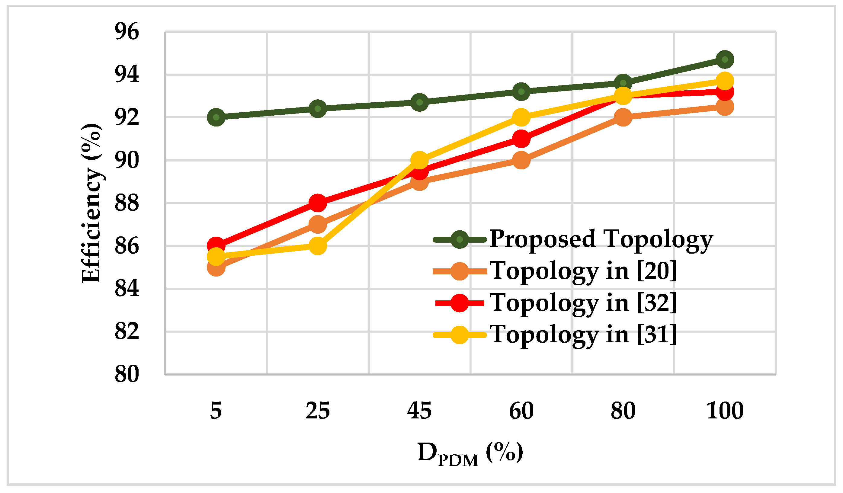
The efficiency of the system is greater than 92% for 0% to 100% of the rated power.
As switching frequency is not varied, soft switching is realized for the whole operating range.
The course of this paper is organized as follows: Section 2 describes the system description of a single-stage AC-AC converter. Simulation and experimental validation of the control technique are performed in Section 3. The conclusion of the paper is presented in Section 4.

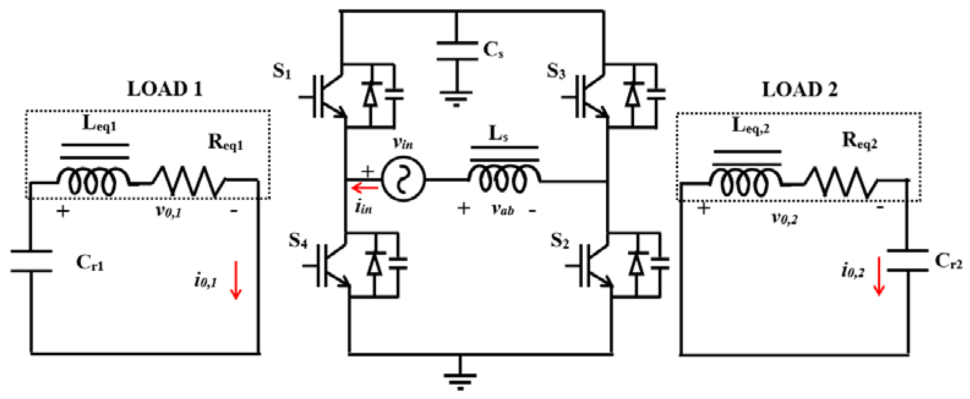
2. System Description

The circuit diagram of the proposed converter topology and its complete working details with specifications are described in the following sub-section.

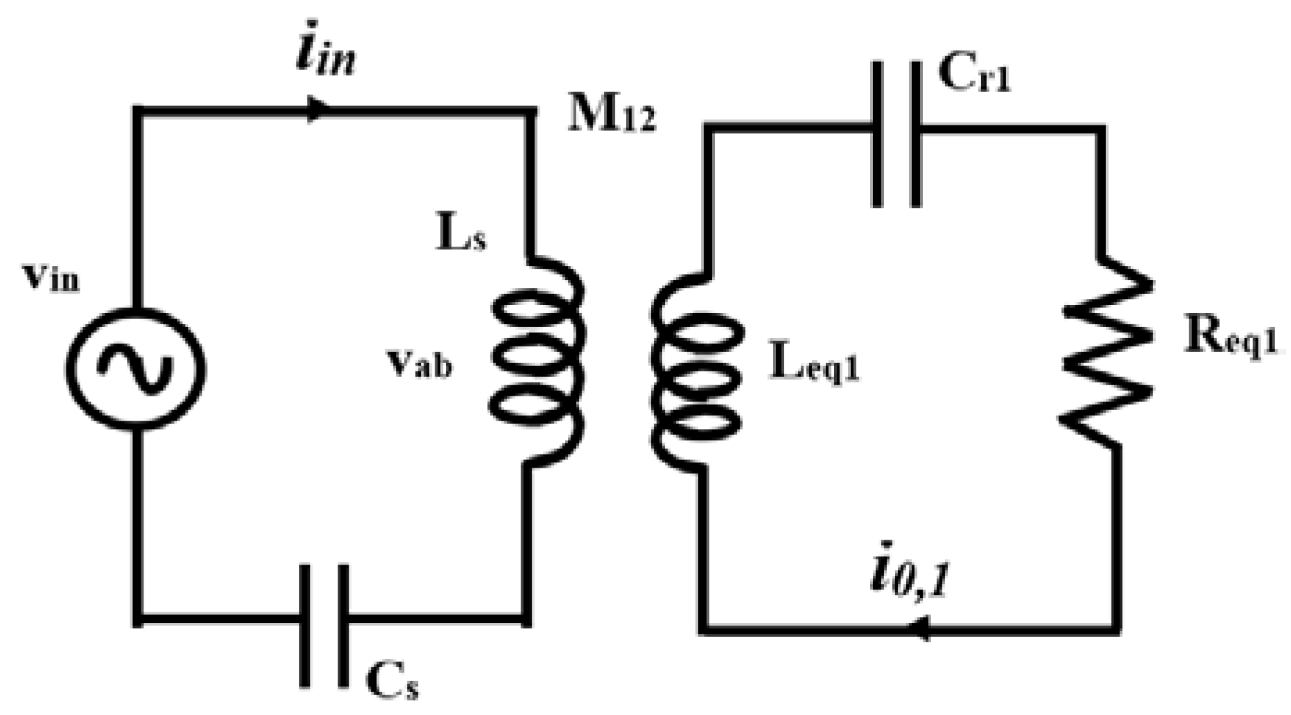
2.1. Circuit Description

The single-stage AC-AC resonant converter proposed in this work converts 50 Hz AC directly into HFAC without a rectifier unit. This avoids the power conversion losses and reduces the number of semiconductor switches which improves the system overall efficiency. For IH application, this topology is most suitable, as power conversion takes place with higher efficiency. The circuit diagram of the single-stage AC-AC converter is shown in Figure 1. It has four IGBTs for converting the 50 Hz AC to HFAC. The inductor Ls acts as the primary coil for transferring power to IH load. The purpose of the source-side inductor (Ls) is to transmit the HFAC supply to IH coil. To create resonance in the transmitter circuit, a capacitor (Cs) is used. The transmitter coil is driven with IGBT switches to produce HFAC. The output voltage of the transmitter is represented as vab. The equivalent circuit of a two-load fed IH system with a transmitter is shown in Figure 2. M12 and M13 represent the mutual inductance of load 1 and load 2 with respect to the source inductance. The equivalent inductances of load 1 and load 2 are represented as Leq1 and Leq2, and the equivalent resistances are Req1 and Req2. The resonant capacitors of load 1 and load 2 are represented as Cr1 and Cr2, respectively. The inverter is triggered in such a manner that 50 Hz AC is converted into HFAC. The switching pulses, typical voltage, and current waveforms are shown in Figure 3.

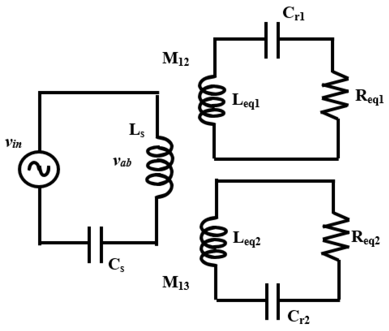
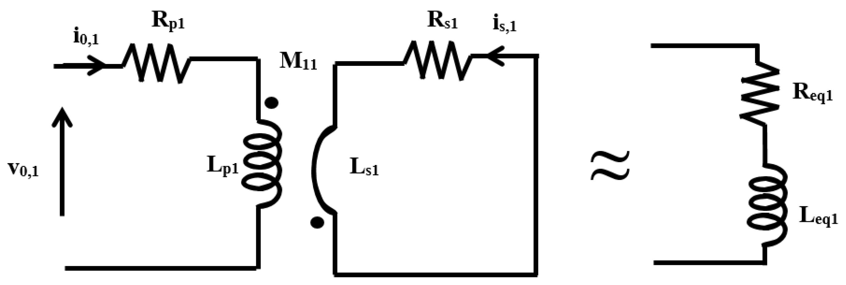
2.2. Induction Heating Modeling

The principle of induction heating resembles the operation of a magnetically coupled transformer where the primary and secondary windings serve to match the source and load voltage. The primary winding is recognized as a work coil and the vessel pan acts as the secondary. In the primary of the transformer, a high-frequency AC is fed and thus eddy currents are generated in the short-circuited secondary side. The heat exerted by the eddy current is channelized and used in heating applications. In order to minimize the complexity of testing the load parameters, it can be represented in the analogous transformer model. The IH cooking system is represented as the reflected parameters of Req and Leq which are the equivalent parameters of the work coil and work piece. An equivalent model of IH for load 1 is shown in Figure 4. The output voltage of load 1 is represented as v0,1, and Rp1 and Lp1 represent the work coil resistance and inductance of load 1. The secondary side (Load) resistance and inductance of load 1 are represented as Rs1 and Lp1, respectively. The mutual inductance of load 1 is denoted as M11.
Applying KVL to the equivalent circuit of load 1, which is shown in Figure 3
( R p 1 + j ω s 1 L p 1 ) i 0 , 1 j ω s 1 M 11 i s , 1 = v 0 , 1
( R s 1 + j   ω s 1 L s 1 ) i s , 1 j ω s 1 i 0 , 1 M 11 = 0
The angular switching frequency of load 1 (ωs1) is
ω s 1 = 2 π f s 1
The current flowing through the load 1 is
i s , 1 = j ω s 1 M 11 i 0 R s 1 + j ω s 1 L s 1
Substituting Equation (4) into Equations (1) and (2),
v 0 , 1 = ( R p 1 + ω s 1 2 M 11 2 R s 1 R s 1 2 + ω s 1 2 L s 1 2 + j ω s 1 [ L p 1 + ω s 1 2 M 11 2 L s 1 R s 1 2 + ω s 1 2 L s 1 2 ] ) i 0 , 1
Req1 and Leq2 are obtained by the real and imaginary terms,
R e q 1 = R p 1 + ω s 1 2 M 11 2 R s 1 R s 1 2 + ω s 1 2 L s 1 2
L e q 1 = L p 1 + ω s 1 2 M 11 2 L s 1 R s 1 2 + ω s 1 2 L s 1 2
The equivalent impedance of load 1 (Zeq1) with the resonant capacitor (Cr1) is
Z e q 1 = R p 1 + ω s 1 2 M 11 2 R s 1 R s 1 2 + ω s 1 2 L s 1 2 + j ω s 1 ( L p 1 + ω s 1 2 M 11 2 L s 1 R s 1 2 + ω s 1 2 L s 1 2 1 ω s 1 2 C r 1 )
The output current flowing through load 1 (i01) is
i 01 = v 01 | Z e q 1 |
The output power of load 1 is
P 01 = i 01 2 R e q 1
The output power computation for load 2 can be performed by replacing the subscript ‘1’ with ‘2’ in Equations (1)–(10). The equivalent circuit of an IH system with a transmitter coil and IH system is shown in Figure 4. The inverter switches are triggered in such a manner that 50 Hz AC is converted into HFAC.
An equivalent model IH system with a transmitter is shown in Figure 5. By applying KVL and solving the expressions as in Equations (1)–(7), the equivalent input impedance (Zin1) by considering load 1 alone is
Z i n 1 = ω s 2 M 12 2 R e q 1 R e q 1 2 + ω s 2 L e q 1 2 + j ω s 1 ( L s + ω s 2 M 12 2 L e q 1 R s 1 2 + ω s 2 L e q 1 2 1 ω s 2 C r 1 + 1 ω s 2 C s )
Similarly, equivalent input impedance (Zin2) by considering load 2 alone is
Z i n 2 = ω s 2 M 13 2 R e q 2 R e q 2 2 + ω s 2 L e q 2 2 + j ω s 1 ( L s + ω s 2 M 13 2 L e q 2 R s 1 2 + ω s 2 L e q 2 2 1 ω s 2 C r 2 + 1 ω s 2 C s )
The input current (iin) is given by
i i n = v i n | Z i n 1 + Z i n 2 |
As the transmitter is triggered at resonance frequency, the input power is given by
P i n = V i n I i n
where Vin and Iin are the rms value of input voltage and current.
The efficiency of IH system is
η 1 = P 01 + P 02 P i n
The efficiency of the system is calculated by considering the conduction loss as expressed in Equation (15).

2.3. Frequency Bifurcation of a Two Coil-Based IH System

Frequency bifurcation is a phenomenon in which frequency of the output power splits from single frequency into dual frequency. This is achieved by adjusting the coupling distance between work coil and work piece (load) greater than the coupling coefficients. The prime concept which lies behind it is the magnetic resonance coupling of the system, which results in improved efficiency without cross interference of the frequency across the loads. Frequency bifurcation represents the input characteristic of the system. In order to analyze the system characteristics, the real-time system is tested with the design specification listed in Table 1. The coupling coefficient for coil and load 1 is [30]
K 12 = ω s 1 + 2 1.5 d 12 2 R s R e q 1
The coupling coefficient for coil and load 2 is [30]
K 13 = ω s 1 + 2 1.5 d 13 2 R s R e q 2
where d12 is distance between the source and load 1 and d13 is distance between source and load 2.
The bifurcated output frequency of load 1 is [30]
ω 01 = ω s 1 + K 12 2 + K 13 2
The bifurcated output frequency of the load 2 is [30]
ω 02 = ω s 1 K 12 2 + K 13 2
Expressions (16) and (17) formulate the relationship between the distance between the source load with the source frequency. In [30], the authors have formulated the relation for the coupling coefficient and source frequency as given in Equations (18) and (19). In this work, the expression is directly used and validated. It is observed that, by locating the transmitting coil and work coil at a distance of 3 cm, the source frequency (25 kHz) is bifurcated as 20 kHz and 33 kHz frequency. These frequencies are used to feed power to load 1 and load 2 by selecting appropriate capacitors to handle the loads independently. That real-time validation is performed in a further section.

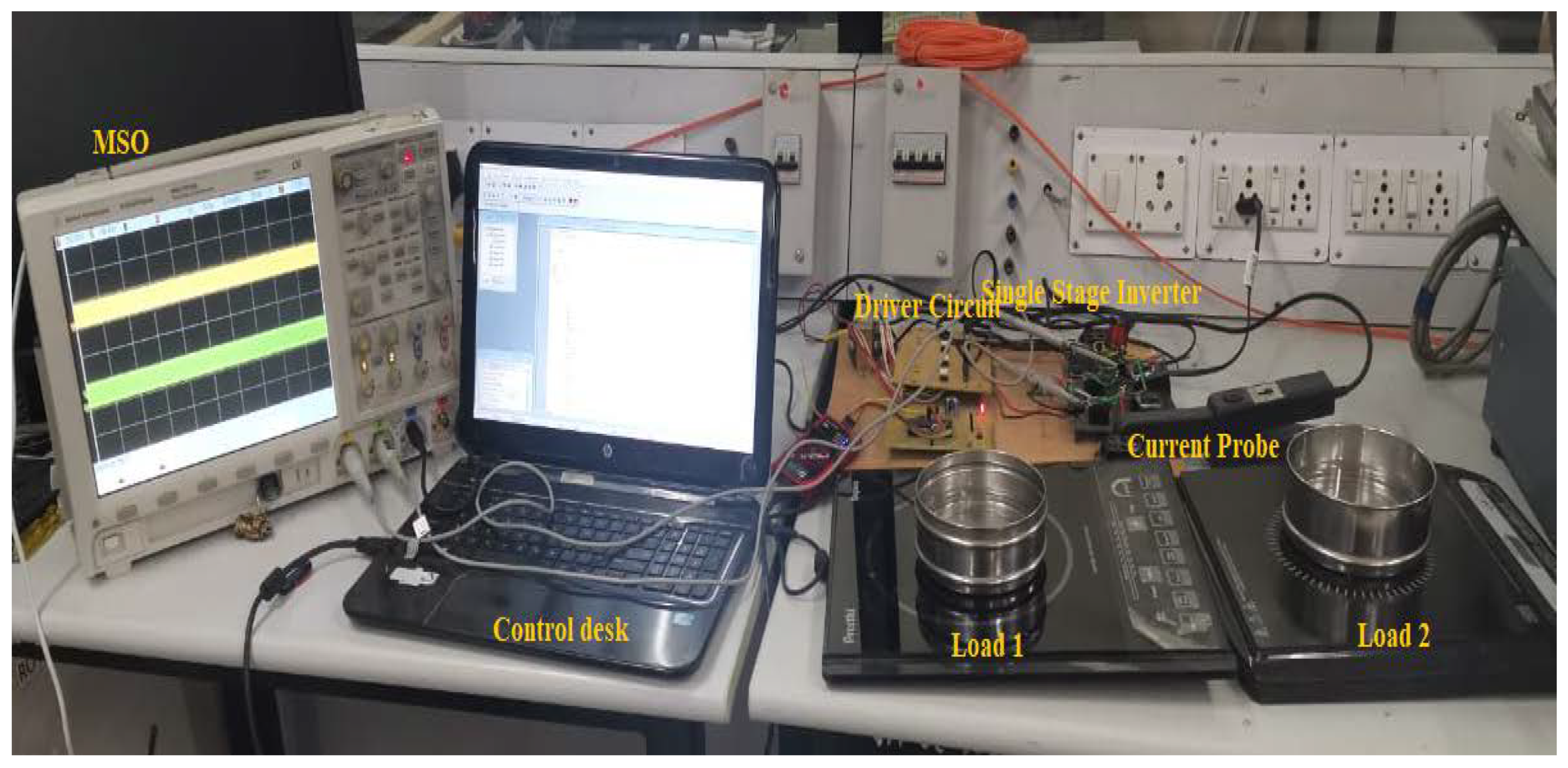
3. Simulation and Experimental Results

A single-stage AC-AC inverter-fed induction cooking device is typically implemented to operate with HFAC of 25 kHz frequency. The inverter pulses are triggered in such a way that the S1 and S2 are turned on for a positive half cycle and S3 and S4 are turned on for a negative half cycle of the HFAC. Due to this switching action, a 50 Hz AC is chopped into a 25 kHz frequency AC. The system is validated by keeping the transmitter coil and work coil at a 3 cm distance. The resonant frequencies of load 1 and load 2 are designed for 20 kHz and 33 kHz. Hence, the capacitors are chosen to operate at that frequency. The output power is performed using the PDM control technique to have smooth control with fewer switching losses [22]. In compliance with the design requirements in Table 1 and Table 2, the single-stage inverter with PDM control is simulated in the MATLAB/Simulink software. A PIC16F877A Controller with the TLP250 Driver IC is used to validate the control mechanism. Four H20R1203 IGBT control switches that can handle 1200 V and 25 A are part of the key circuit. For measuring the current, the SIGLENT CP4060 current probe is used, and the oscilloscope is used for capturing waveforms. The advanced FLIR E75 24° thermal camera is used to record the thermal image of the load in real time. The configuration for the test setup is shown in Figure 6.

3.1. Dual Load Operation

A simulation of the proposed system is performed in MATLAB/Simulink. The simulated switching pulses (Vs1, Vs2, Vs3, Vs4) for the switches S1, S2. S3 and S4 are shown in Figure 7a and its associated waveforms of voltage and currents for load 1 and load 2 are shown in Figure 7b,c, respectively. In Figure 7d, the expanded waveform of output voltage (v0,1) and current (io,1) waveform for load 1 is demonstrated. Similarly, in Figure 7e, the enhanced view of output voltage (v0,2) and current (i0,2) waveform for load 2 is shown. In real time, the system is tested for 1000 W and the test results of switching pulses are illustrated in Figure 7f. The output voltage and current waveform for load 1 and load 2 are presented in Figure 7g,h, respectively. The zoomed view of experimental voltage and current waveform of load 1 is shown in Figure 7i and load 2 is shown in Figure 7j. It is observed from the output voltage and waveforms that the envelope follows the 50 Hz sinusoidal AC waveform and there is a chopping of high-frequency signal within one complete cycle. The capacitor of each load is chosen in such a manner that it acts as the minimum reactance path for its resonant frequency and open circuit for other frequencies. It enumerates that load 1 responds to 20 kHz frequency, whereas load 2 responds to 33 kHz supply. For other frequencies, the loads remain open circuit. The rms value of the load 1 current is Io,1rms is 7.07 A and I0,2rms is 6.36 A. The output power P0,1 = 7.072 × 11 = 550 W and P0,2 = 6.362 × 11 = 445 W for 11 Ω equivalent resistance. The total input power is Pin = Vin × Iin = 1050.69 W and efficiency is 94.7%. The current spectrum of load 1 and load 2 are illustrated in Figure 7k,l, respectively. It confines that there is no cross interference of frequencies across the loads, i.e., the fundamental frequencies of load 1 is 20 kHz and load 2 is 33 kHz. The simulation outcomes are in accordance with the experimental results.

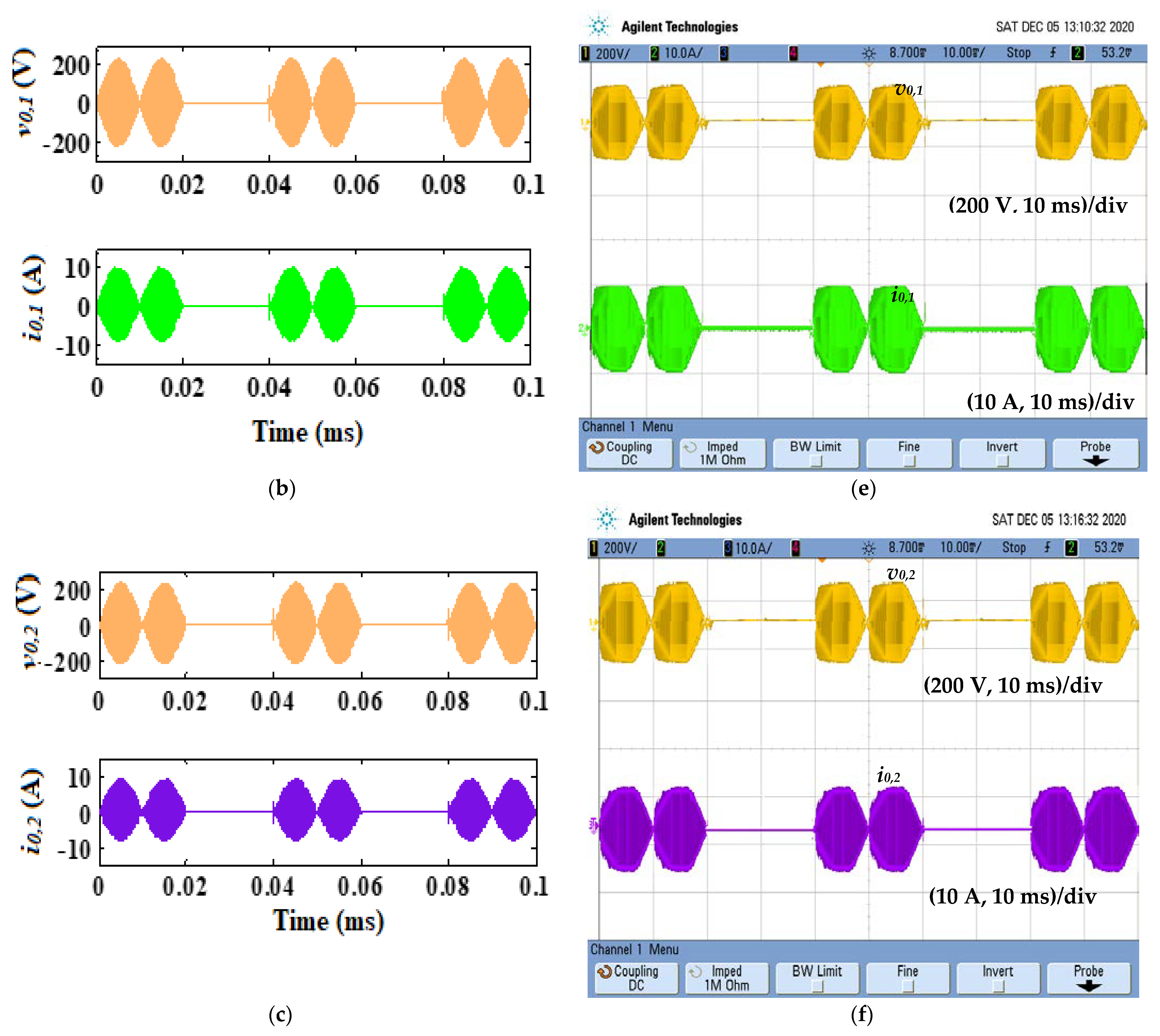
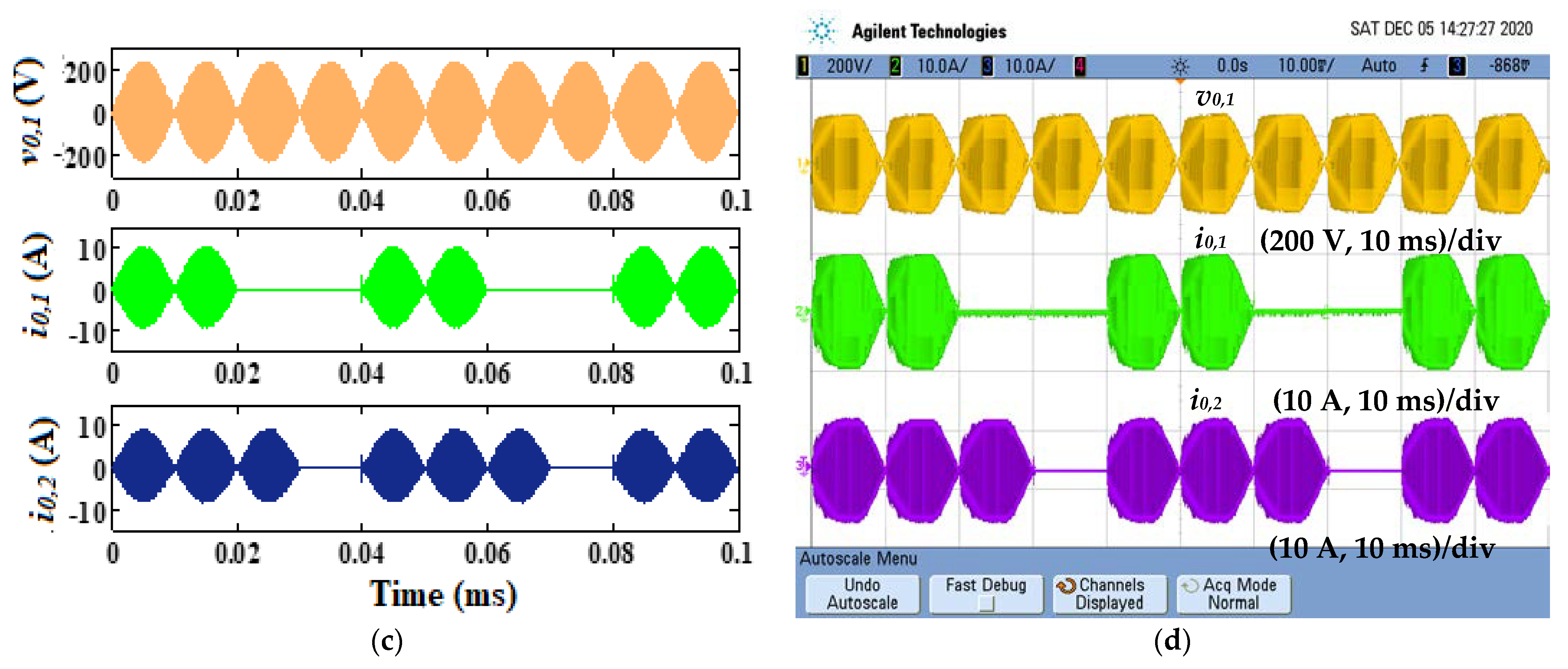
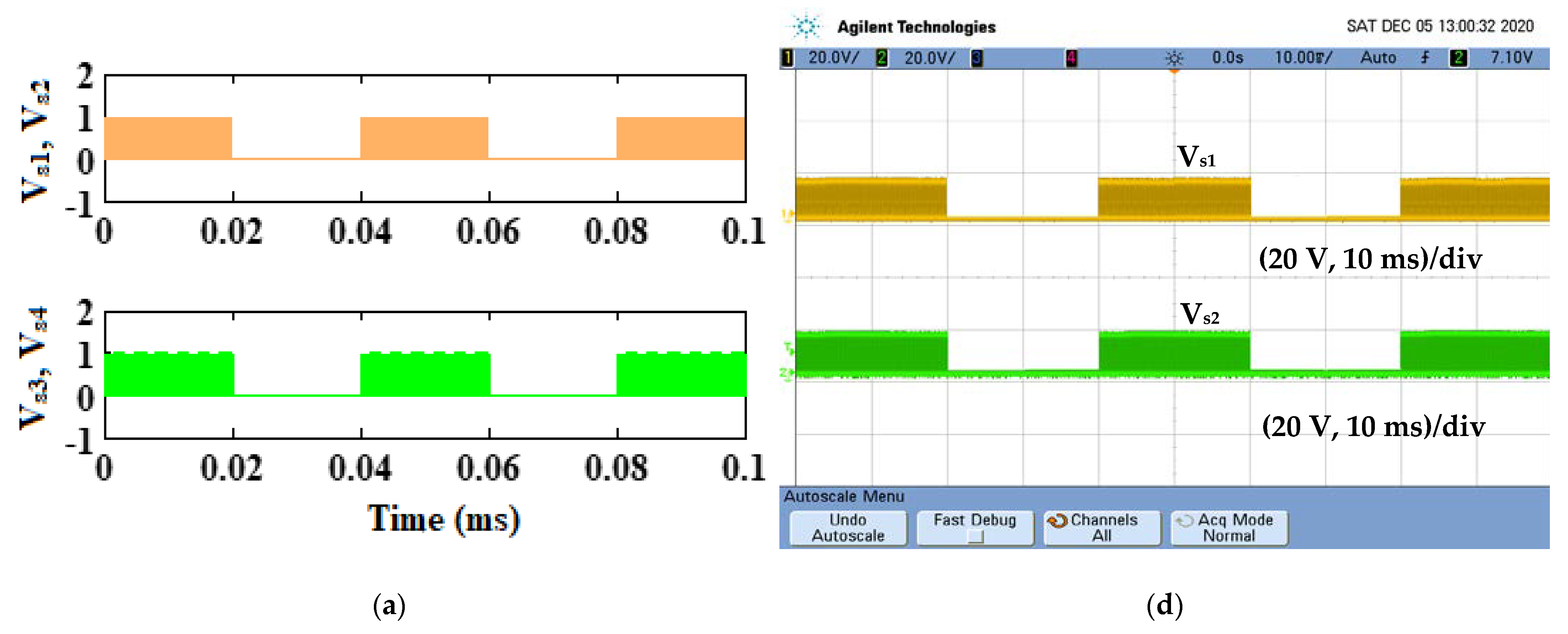
3.2. PDM Based Dual Output Power Control for Induction Heating Load

A smooth and accurate power control technique is required in the IH system to vary the temperature as per the load requirement. PDM-based control logic is used to vary the output power for a single-stage AC-AC converter-fed induction cooking system. The PDM pulses are generated in such a manner that, during the turn-on period of low frequency pulses (TD,on), high frequency pulses are applied to inverter switches and masked during the turn-off period. The duty cycle of PDM signal (DPDM) with total period TDPDM is
D P D M = T D , o n T D P D M
The relationship between the rated power (Prated) and the output power (P0) with DPDM is
P 0 = D PDM P r a t e d
To have control over the output power, an inverter is operated with various DPDM. As per specifications, load 1 is designed to handle 550 W and load 2 is designed to handle 445 W with Req = 11 Ω. With 50% of the DPDM, the output power is 275 W for load 1 and 223 W for load 2. The corresponding waveforms are illustrated in Figure 8. The simulation waveforms of the switching pulses for the inverter are shown in Figure 8a. The corresponding output voltage and current waveforms of load 1 and load 2 are shown in Figure 8b,c, respectively. Experimental switching pulses are shown in Figure 8d and its corresponding voltage and current waveform of load 1 and load 2 is illustrated in Figure 8e,f, respectively. It is inferred from the results that the net power developed in load 1 is reduced to 275 W and load 2 is reduced to 222.5 W with 50% DPDM. The output power is reduced due to the dead band in the output voltage and current. When the inverter’s switching pulses are switched off due to the system time constants, the instantaneous current is not zero.
As the set power is varied from 550 W to 412.5 W in load 1 and from 445 W to 334 W in load 2, the controller generates the pulses with 75% DPDM to achieve the set power, and its corresponding simulated switching pulses are shown in Figure 9a. The simulated output voltage and current waveforms corresponding to 75% DPDM of load 1 and load 2 are shown in Figure 9b,c, respectively. As the set power is varied, the DPDM of the inverter is adjusted to obtain the desired output power. The same has been tested in real time and experimental results are validated. Figure 9d illustrates the switching pulses of the inverter. The experimental output voltage and current waveforms of load 1 and load 2 are shown in Figure 9e,f, respectively. The efficiency of various DPDM is tabulated in Table 3 and it is inferred that the minimum efficiency of the system is 92% at 5% DPDM.

3.3. Independent Power Control

During the real-time operation of a multi-load induction cooking system, individual load requires an independent power control, exclusive to the operation of other loads. With respect to this, the PDM control technique ensures the individual power control of different loads [33]. The system is evaluated with the following two scenarios.
(i)
Load 1 requires 137.5 W and load 2 requires 445 W. In this case, the PDM control signal is chosen with 25% of DPDM for 20 kHz switching and 100% DPDM for 33 kHz switching frequency.
(ii)
Load 1 requires 275 W and load 2 requires 356 W. In this case, the PDM control signal is chosen with 50% of DPDM for 20 kHz switching and 75% DPDM for 33 kHz switching frequency.
The simulation and experimental output voltage and current waveforms of 25% DPDM for load 1 and 100% DPDM for load 2 are shown in Figure 10a,b, respectively. From the results, it is concluded that the discontinuous current of load 1 results in a reduction in output power without disturbing load 2. Similarly, for scenario 2, the output voltage and current waveforms of load 1 and load 2 for 50% DPDM for load 1 and 75% DPDM for load 2 are shown in Figure 10c,d. It confirms that the developed system is good enough to handle both the loads with two different power setting. The efficiency of the IH system for different DPDM values is shown in Table 4. The control scheme can facilitate power control to multi-load applications with reduced physical components. Additionally, it has the unique advantage of achieving independent power control with higher efficiency, ensuring constant frequency operation. Moreover, the control scheme can make the inverter operate at ZVS for a wide range of power control.

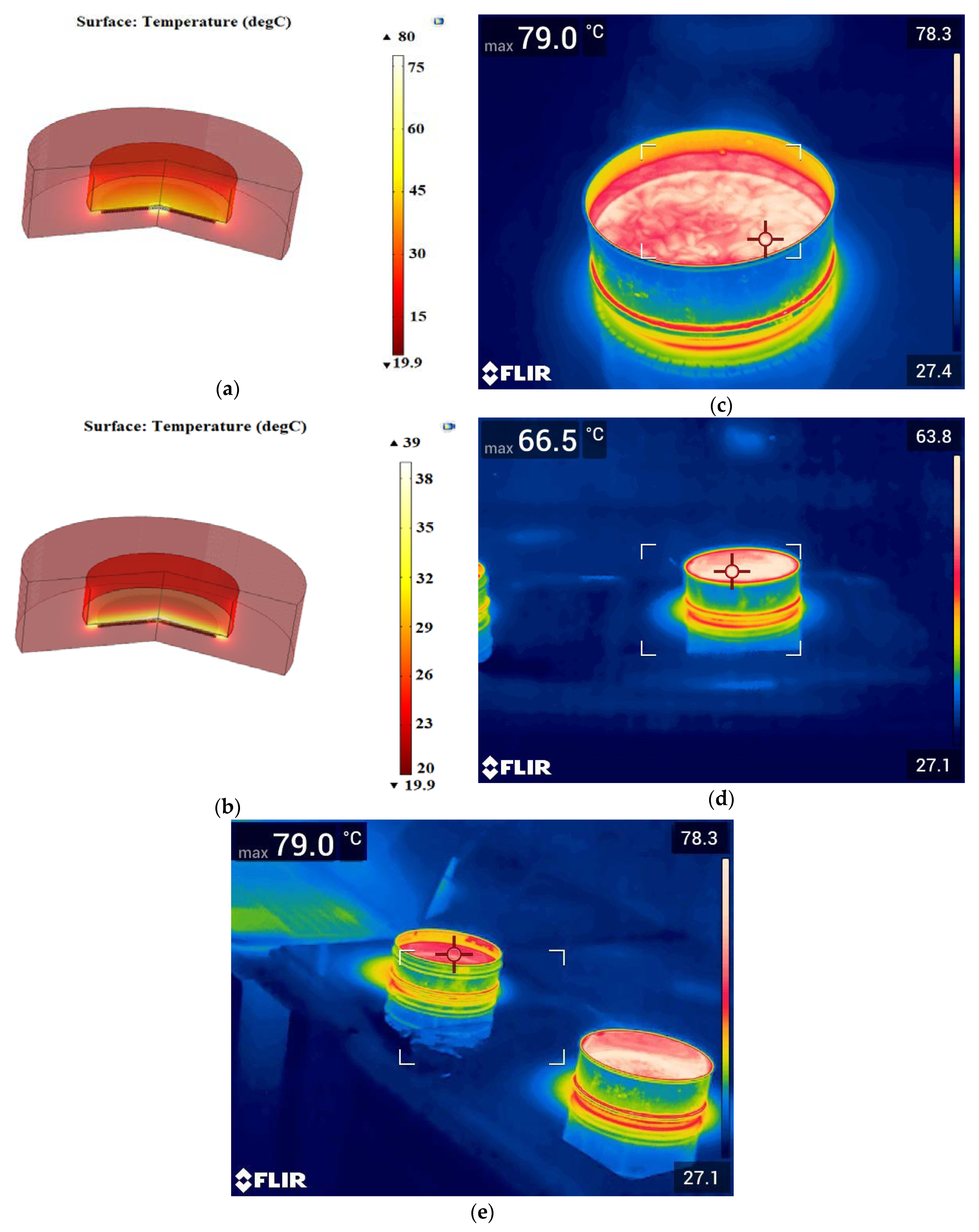
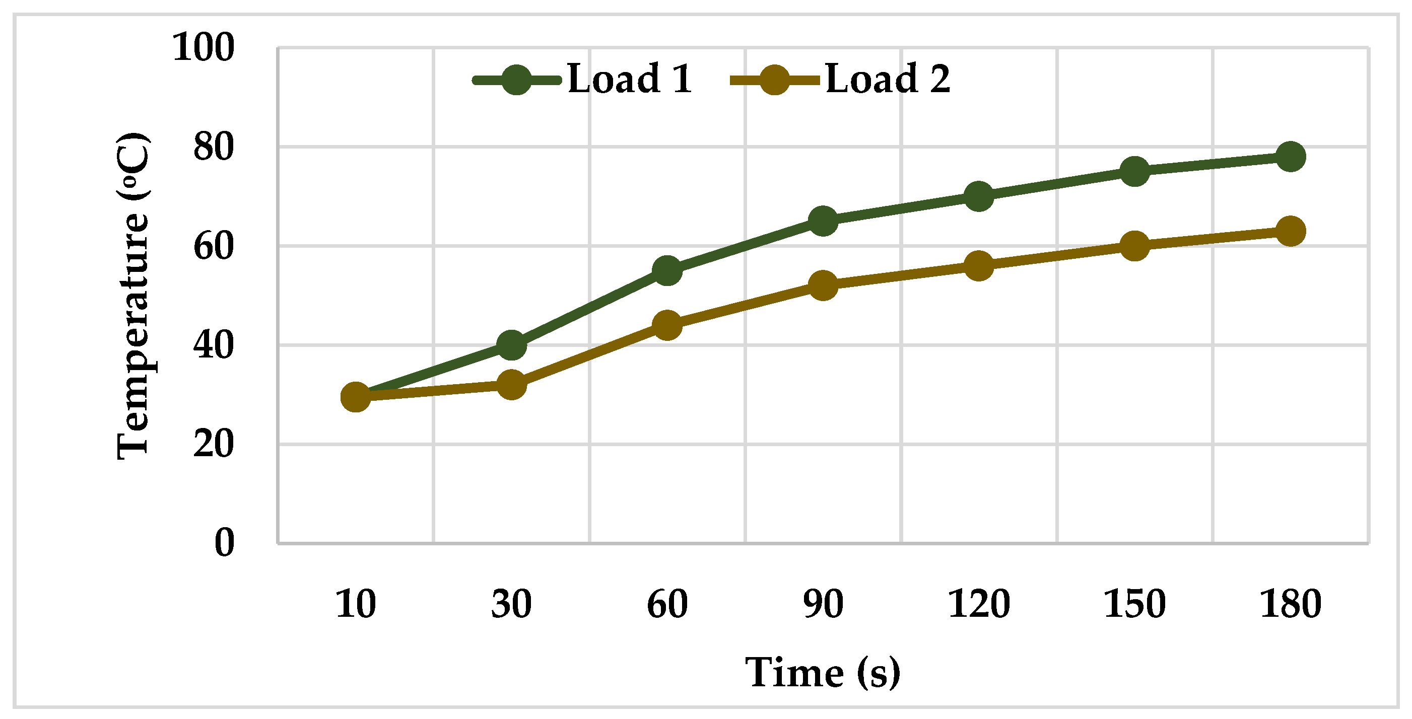
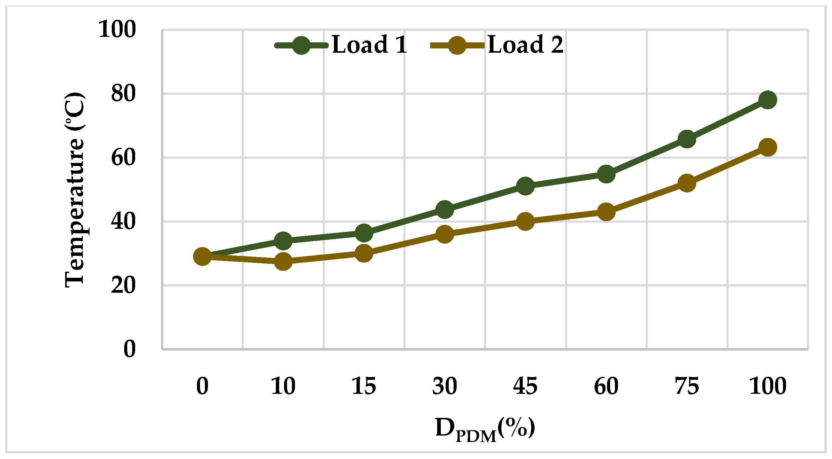
3.4. Thermal Analysis of Load

In the COMSOL environment, the traditional IH structure is modelled on a 2-dimensional, axis-symmetrical, with 28-turns work coil, each of 3 mm diameter. The average diameter of the operating coil is 128 mm and the vessel carrying water is considered as a load. The system is solved by means of a magnetic field heat transfer solver in solid physics to achieve transient frequency solutions. Input parameters for transient frequency analysis include the geometry of the IH system, the magnetic properties of the load, the frequency and the output of the current. Using magnetic and heat transfer physics, COMSOL estimates the heat which develops on the load. As a user-defined equation in COMSOL, the switching frequency and current flowing through each load is evaluated and fed as input. The rate of heat generation on the work piece is estimated using the thermal conductance model of the IH system for various intervals. In this model, the surface-to-ambient heat radiation boundary conditions are used on all the external surfaces for performing the temperature analysis. The geometry is messed into 10,254 triangular elements for solving the system. The FLIR E75 24° advanced thermal imager is used to capture the load thermal image. The simulated and experimental temperature profiles for load 1 and load 2 are shown in Figure 11a–d. The thermal rise is recorded at time t = 180 s for both the loads, and it is observed that the highest temperature difference is 16%, as the power difference between the two loads is 19%. It implies that the produced temperature and power developed on the load are directly proportional with each other. The overall thermal image of the multi-load fed IH system is shown in Figure 9e.
The increase in temperature at different instants is shown in Figure 12. It is found that at t = 180 s, the heat developed in load 1 is 79 °C and in load 2 is 66.5 °C. It is inferred that the temperature increases with respect to time for both the loads. Similarly, the variation of temperature with respect to DPDM is shown in Figure 13. From the response, it is concluded that the temperature is varied by adjusting the DPDM. The total modular power loss for various DPDM with existing topology is shown in Figure 14. It is inferred that the proposed system possesses minimum losses for the variation in DPDM.
The comparison of the proposed topology with respect to the existing topologies are listed in Table 5. It is inferred that the proposed IH system possesses higher efficiency with the minimum semiconductor switches. The efficiency of the proposed system with respect to the existing topologies is shown in Figure 15. The maximum efficiency occurs at 100% DPDM. Additionally, for the remaining values of DPDM, efficiency is greater than 92%. Thus, the proposed control technique can be used for a single/two induction cooking system.

4. Conclusions

In this work, a single-stage AC-AC series resonant inverter for a cooking application feeding power to multiple loads is proposed using a single supply frequency. The proposed scheme is tested by placing the transmitter coil and work coil at a distance of 3 cm, which produces the dual frequencies at the output side for a 25 kHz source frequency. The bifurcated frequencies, such as 20 kHz and 33 kHz, are used to power load 1 and load 2, respectively. The current spectrum confines that there is no cross-frequency interference across the loads. The output power control is performed by adjusting the duty cycle of the PDM signal. The temperature in both the loads is studied using an FLIR thermal imager for various time instants. The summary of this work is listed as follows:
  • Output power is controlled from 100% to 0% of the rated power.
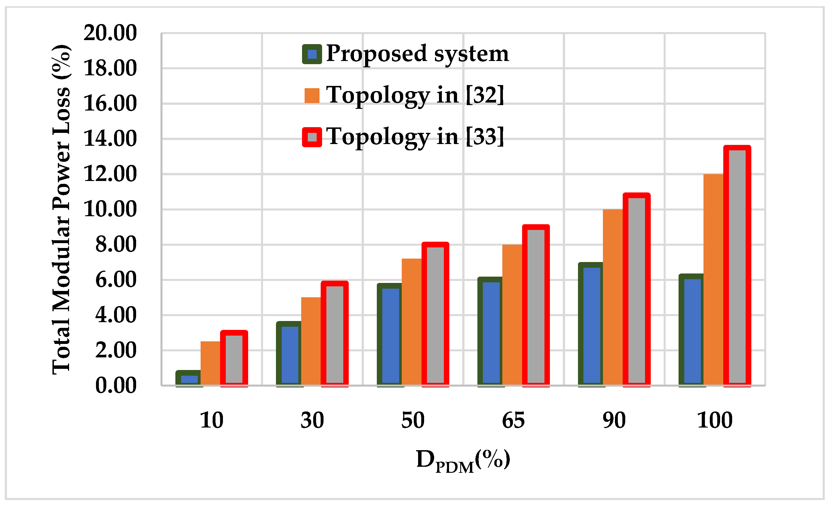
  • The proposed inverter possesses higher efficiency of about 94.7% at 100% DPDM and is greater than 92% for other values of DPDM.
  • Independent power control is achieved.
  • The output power can be regulated to any value within the rated power.
  • At rated power, the system possesses 5% less power losses as compared with the existing articles [31,32].
  • As switching frequency is not varied, soft switching is realized for the whole operating range.
  • The PDM frequency is chosen as 25 Hz, which results in no noise.
From the test results, it can be concluded that the proposed system produces multiple output frequencies with a single source. Though the tested system is able to handle two loads, the power rating cannot be maintained as uniform due to multi-frequency operations. Thus, a converter topology is required to produce uniform power distribution across all loads. This work can be extended for more loads by varying the distance.

Author Contributions

Conceptualization, P.V. and S.D.; methodology, K.B.; software, S.B.T.; validation, P.V., S.D. and S.B.T.; formal analysis, B.N.; investigation, P.V.; resources, B.N.; data curation, P.V.; writing—original draft preparation, P.V.; writing—review and editing, P.V., S.D., S.B.T., K.B. and B.N; visualization, B.N.; supervision, B.N.; project administration, S.B.T.; funding acquisition, B.N. All authors have read and agreed to the published version of the manuscript.

Funding

This research received no external funding.

Institutional Review Board Statement

Not applicable.

Informed Consent Statement

Not applicable.

Data Availability Statement

Not applicable.

Conflicts of Interest

The authors declare no conflict of interest.

Nomenclature

ReqEquivalent load resistance (Ω)
LeqEquivalent load inductance (H)
VabSupply voltage (V)
Rp1Work coil resistance of load 1 (Ω)
Rp2Work coil resistance of load 2 (Ω)
Lp1Primary inductance of load 1 (H)
Lp2Primary inductance of load 2 (H)
Ls1Secondary inductance of load 1 (H)
Ls2Secondary inductance of load 2 (H)
VmMaximum peak value of the input voltage (V)
θAngle difference between voltage and current (degree)
M12Mutual inductance of source on load 2 (H)
M21Mutual inductance of source on load 1 (H)
Zeq1Equivalent impedance of load 1 (Ω)
Zeq2Equivalent impedance of load 2 (Ω)
η1Efficiency of load 1
η2Efficiency of load 2
v0,1Load 1 voltage (V)
v0,2Load 2 voltage (V)
i0,1Load 1 current (A)
i0,2Load 2 current (A)
Req1Equivalent load resistance of load 1 (Ω)
Req2Equivalent load resistance of load 2 (Ω)
Leq1Equivalent load inductance of load 1 (H)
Leq2Equivalent load inductance of load 2 (H)
Cr1Resonant capacitor of load 1 (F)
Cr2Resonant capacitor of load 2 (F)
ωsAngular switching frequency (rad/sec)
LsInput inductor (H)
RsSource coil resistance (Ω)
CsSource capacitor (F)
PratRated output power (W)
fPDMPDM switching frequency (Hz)
frResonant frequency (Hz)
fr1Resonant frequency of load 1 (Hz)
fr2Resonant frequency of load 2 (Hz)
ωr1Angular resonant frequency of load 1 (rad/sec)
ωr2Angular resonant frequency of load 2 (rad/sec)
d12Distance between source and load 1 (cm)
d13Distance between source and load 2 (cm)

References

  1. Acero, J.A.; Burdio, J.M.; Barragan, L.A.; Navarro, D.; Alonso, R.M.; Garcia, J.R.; Monterde, F.; Hernandez, P.; Llorente, S.; Garde, I. The domestic induction heating appliance: An overview of recent research. In Proceedings of the 2008 Twenty-Third Annual IEEE Applied Power Electronics Conference and Exposition, Austin, TX, USA, 24–28 February 2008; Volume 16, pp. 651–657. [Google Scholar] [CrossRef]
  2. Park, S.M.; Jang, E.; Joo, D.; Lee, B.K. Power Curve-Fitting Control Method with Temperature Compensation and Fast-Response for All-Metal Domestic Induction Heating Systems. Energies 2019, 12, 2915. [Google Scholar] [CrossRef] [Green Version]
  3. Yilmaz, I.; Ermis, M.; Cadirci, I.; Yılmaz, I. Medium frequency induction melting furnace as a load on the power system. In Proceedings of the 2011 IEEE Industry Applications Society Annual Meeting, Orlando, FL, USA, 9–13 October 2011; Volume 48, pp. 1–12. [Google Scholar] [CrossRef]
  4. Egalon, J.; Caux, S.; Maussion, P.; Souley, M.; Pateau, O. Multiphase System for Metal Disc Induction Heating: Modeling and RMS Current Control. IEEE Trans. Ind. Appl. 2012, 48, 1692–1699. [Google Scholar] [CrossRef] [Green Version]
  5. Millán, I.; Burdío, J.; Acero, J.A.; Lucía, O.; Llorente, S. Series resonant inverter with selective harmonic operation applied to all-metal domestic induction heating. IET Power Electron. 2011, 4, 587. [Google Scholar] [CrossRef]
  6. Lucía, O.; Burdío, J.M.; Millán, I.; Acero, J.; Barragán, L.A. Efficiency-Oriented Design of ZVS Half-Bridge Series Resonant Inverter With Variable Frequency Duty Cycle Control. IEEE Trans. Power Electron. 2010, 25, 1671–1674. [Google Scholar] [CrossRef]
  7. Sarnago, H.; Lucía, Ó.; Pérez-Tarragona, M.; Burdío, J.M. Dual-Output Boost Resonant Full-Bridge Topology and its Modu-lation Strategies for High-Performance Induction Heating Applications. IEEE Trans. Ind. Electron. 2016, 63, 3554–3561. [Google Scholar] [CrossRef]
  8. Park, N.J.; Lee, D.Y.; Hyun, D.S. A power control scheme with constant switching frequency in class-D inverter for induc-tion-heating jar application. IEEE Trans. Ind. Electron. 2007, 54, 1252–1260. [Google Scholar] [CrossRef]
  9. Vishnuram, P.; Ramasamy, S.; Sureshkumar, A.; Suresh, P. Phase-Locked Loop-Based Asymmetric Voltage Cancellation for the Power Control in Dual Half-Bridge Series Resonant Inverter Sharing Common Capacitor for Induction Heating Applications. J. Control Autom. Electr. Syst. 2019, 30, 1094–1106. [Google Scholar] [CrossRef]
  10. Trentin, A.; Zanchetta, P.; Clare, J.; Wheeler, P. Automated Optimal Design of Input Filters for Direct AC/AC Matrix Converters. IEEE Trans. Ind. Electron. 2011, 59, 2811–2823. [Google Scholar] [CrossRef]
  11. Hao, L.L.; Hu, A.P.; Covic, G.A. A direct ac-ac converter for inductive power-transfer systems. IEEE Trans. Power Electron. 2012, 27, 661–668. [Google Scholar]
  12. Yamamoto, E.; Hara, H.; Uchino, T.; Kawaji, M.; Kume, T.J.; Jun Koo, K.; Krug, H.P. Development of MCs and its applications in industry. IEEE Ind. Electron. Mag. 2011, 5, 4–12. [Google Scholar] [CrossRef]
  13. Ahmed, N.A.; Nakaoka, M. Boost-half-bridge edge resonant soft switching PWM high-frequency inverter for consumer in-duction heating appliances. Proc. Electr. Power Appl. 2006, 153, 932–938. [Google Scholar] [CrossRef]
  14. Forest, F.; Faucher, S.; Gaspard, J.; Montloup, D.; Huselstein, J.; Joubert, C. Frequency-Synchronized Resonant Con-verters for the Supply of Multiwinding Coils in Induction Cooking Appliances. IEEE Trans. Ind. Electron. 2007, 54, 441–452. [Google Scholar] [CrossRef]
  15. Chen, M.-P.; Chen, J.-K.; Murata, K.; Nakahara, M.; Harada, K. Surge analysis of induction heating power supply with PLL. IEEE Trans. Power Electron. 2001, 16, 702–709. [Google Scholar] [CrossRef]
  16. Sarnago, H.; Óscar, L.; Popa, I.; Burdío, J. Constant-Current Gate Driver for GaN HEMTs Applied to Resonant Power Conversion. Energies 2021, 14, 2377. [Google Scholar] [CrossRef]
  17. Carretero, C.; Lucia, O.; Acero, J.; Burdio, J.M. Phase-shift modulation in double half-bridge inverter with common resonant capacitor for induction heating appliances. IET Power Electron. 2015, 8, 1128–1136. [Google Scholar] [CrossRef]
  18. Komeda, S.; Fujita, H. A Phase-Shift-Controlled Direct AC-to-AC Converter for Induction Heaters. IEEE Trans. Power Electron. 2017, 33, 4115–4124. [Google Scholar] [CrossRef]
  19. Burdio, J.; Barragan, L.; Monterde, F.; Navarro, D.; Acero, J.A. Asymmetrical Voltage-Cancellation Control for Full-Bridge Series Resonant Inverters. IEEE Trans. Power Electron. 2004, 19, 461–469. [Google Scholar] [CrossRef]
  20. Nagarajan, B.; Rama, R.S. CFAVC scheme for high frequency series resonant inverter-fed domestic induction heating system. Int. J. Electron. 2016, 103, 160–176. [Google Scholar] [CrossRef]
  21. Ahmed, N.A. High-Frequency Soft-Switching AC Conversion Circuit with Dual-Mode PWM/PDM Control Strategy for High-Power IH Applications. IEEE Trans. Ind. Electron. 2010, 58, 1440–1448. [Google Scholar] [CrossRef]
  22. Esteve, V.; Kilders, E.S.; Jordan, J.; Dede, E.J.; Cases, C.; Maset, E.; Ejea, J.B.; Ferreres, A. Improving the Efficiency of IGBT Series-Resonant Inverters Using Pulse Density Modulation. IEEE Trans. Ind. Electron. 2011, 58, 979–987. [Google Scholar] [CrossRef]
  23. Forest, F.; Laboure, E.; Costa, F.; Gaspard, J. Principle of a multi-load/single converter system for low power induction heating. IEEE Trans. Power Electron. 2000, 15, 223–230. [Google Scholar] [CrossRef]
  24. Burdio, J.M.; Monterde, F.; Garcia, J.R.; Barragan, L.A.; Martinez, A. A two-output series-resonant inverter for induction-heating cooking appliances. IEEE Trans. Power Electron. 2005, 20, 815–822. [Google Scholar] [CrossRef]
  25. Haerinia, M.; Afjei, E. Investigation of receiving pot core effect on magnetic flux density in inductive coupling-based wireless power transfer. In Proceedings of the 2016 International Symposium on Power Electronics, Electrical Drives, Automation and Motion (SPEEDAM), Institute of Electrical and Electronics Engineers (IEEE), Piscataway, NJ, USA, 24–26 June 2016; pp. 541–545. [Google Scholar]
  26. Cannon, B.L.; Hoburg, J.F.; Stancil, D.D.; Goldstein, S.C. Magnetic Resonant Coupling As a Potential Means for Wireless Power Transfer to Multiple Small Receivers. IEEE Trans. Power Electron. 2009, 24, 1819–1825. [Google Scholar] [CrossRef] [Green Version]
  27. Zhang, Y.; Lu, T.; Zhao, Z.; He, F.; Chen, K.; Yuan, L. Selective Wireless Power Transfer to Multiple Loads Using Receivers of Different Resonant Frequencies. IEEE Trans. Power Electron. 2015, 30, 6001–6005. [Google Scholar] [CrossRef]
  28. Lyu, Y.L.; Meng, F.Y.; Yang, G.H.; Che, B.J.; Wu, Q.; Sun, L.; Erni, Q.; Li, J.L.-W. A method of using nonidentical resonant coils for frequency splitting elimination in wireless power transfer. IEEE Trans. Power Electron. 2015, 30, 6097–6107. [Google Scholar] [CrossRef]
  29. Choi, W.-K.; Park, C.-W.; Lee, K. Circuit Analysis of Achievable Transmission Efficiency in an Overcoupled Region for Wireless Power Transfer Systems. IEEE Syst. J. 2017, 12, 3873–3876. [Google Scholar] [CrossRef]
  30. Narayanamoorthi, R.; Vimala Juliet, A.; Chokkalingam, B. Cross Interference Minimization and Simultaneous Wireless Power Transfer to Multiple Frequency Loads Using Frequency Bifurcation Approach. IEEE Trans. Power Electron. 2019, 34, 10898–10909. [Google Scholar] [CrossRef]
  31. Vishnuram, P.; Ramasamy, S.; Pradeep, V. Fuzzy Logic-Based Pulse Density Modulation Scheme for Mitigating Uncertainties in AC–AC Resonant Converter Aided Induction Heating System. J. Circuits Syst. Comput. 2018, 28. [Google Scholar] [CrossRef]
  32. Vishnuram, P.; Ramachandiran, G.; Ramasamy, S. A novel power control technique for series resonant inverter-fed induc-tion heating system with fuzzy-aided digital pulse density modulation scheme. Int. J. Fuzzy Syst. 2018, 20, 1115–1129. [Google Scholar] [CrossRef]
  33. Vishnuram, P.; Ramachandiran, G. A simple multi-frequency multiload independent power control using pulse density modulation scheme for cooking applications. Int. Trans. Electr. Energy Syst. 2021, 31, 12771. [Google Scholar] [CrossRef]
Figure 1. Circuit diagram of single-stage AC-AC converter.
Energies 14 04799 g001
Figure 2. Equivalent circuit of two loads fed IH system.
Energies 14 04799 g002
Figure 3. Typical voltage and current waveforms.
Energies 14 04799 g003
Figure 4. Equivalent model of IH load 1.
Energies 14 04799 g004
Figure 5. Equivalent model of IH system with transmitter.
Energies 14 04799 g005
Figure 6. The test set up of the IH system.
Energies 14 04799 g006
Figure 7. Main waveforms for 100% DPDM: simulation waveforms (a) switching pulses, (b) output voltage and current of load 1, (c) output voltage current of load 2, (d) zoomed view of the output voltage current of load 1, (e) zoomed view of the output voltage current of load 2, experimental waveforms (f) switching pulses, (g) output voltage and current of load 1, (h) output voltage current of load 2, (i) zoomed view of the output voltage current of load 1, (j) zoomed view of the output voltage current of load 2, (k) current spectrum of load 1, (l) current spectrum of load 2.
Energies 14 04799 g007aEnergies 14 04799 g007b
Figure 8. Main waveforms for 50% DPDM: simulation waveforms (a) switching pulses, (b) output voltage and current of load 1, (c) output voltage and current of load 2, experimental waveforms (d) switching pulses, (e) output voltage and current of load 1, (f) output voltage and current of load 2.
Energies 14 04799 g008aEnergies 14 04799 g008b
Figure 9. Main waveforms for 75% DPDM: simulation waveforms (a) switching pulses, (b) output voltage and current of load 1, (c) output voltage and current of load 2, experimental waveforms (d) switching pulses, (e) output voltage and current of load 1, (f) output voltage and current of load 2.
Energies 14 04799 g009
Figure 10. Voltage and currents waveform of 25% DPDM for load 1 and 100% DPDM for load 2 (a) simulation, (b) hardware, voltage and currents waveform of 50% DPDM for load 1 and 75% DPDM for load 2 (c) simulation, (d) hardware.
Energies 14 04799 g010aEnergies 14 04799 g010b
Figure 11. Simulated thermal image of (a) load 1 (b) load 2; experimental thermal image of (c) load 1, (d) load 2, (e) load 1 and load 2.
Energies 14 04799 g011
Figure 12. Variations of temperature with respect to time.
Energies 14 04799 g012
Figure 13. Variations of temperature with respect to DPDM.
Energies 14 04799 g013
Figure 14. Total modular power loss.
Energies 14 04799 g014
Figure 15. Efficiency variations for distinct load power.
Energies 14 04799 g015
Table 1. Design specifications of AC-AC converter.
ComponentsLoad 1Load 2
Equivalent load resistance, Req11 Ω11 Ω
Equivalent load inductance, Leq0.12 mH0.12 mH
Resonant capacitor, Cr520 nF200 nF
Input inductor, Ls200 μH
Source capacitor Cs200 nF
Table 2. Specific requirements.
ParametersValue
Vin230 V (RMS), 50 Hz
Prat1000 W
fPDM25 Hz
fr25 kHz
fr120 kHz
fr233 kHz
Table 3. Efficiency for various DPDM.
S.NoDPDM (%)Pin (W)Load 1Load 2P0 (W)Efficiency (%)
Load 1Load 2I01rms (A)P01 (W)I02rms (A)P02 (W)
11001001050.697.075506.3644599594.7
28080850.436.324405.6935679693.6
36060640.565.483304.9326759793.2
44545483.014.74247.54.27200.25447.7592.7
52525269.213.54137.53.18111.25248.7592.4
65554.081.5827.51.4222.2549.7592
Table 4. Efficiency of the IH system with independent control.
S.NoDPDM (%)Pin (W)Load 1Load 2P0 (W)Efficiency (%)
Load 1Load 2I01rms (A)P01 (W)I02rms (A)P02 (W)
110080966.927.075505.6935690693.7
210050825.677.075504.50222.5772.593.56
310010637.337.075502.0144.5594.593.28
485100974.376.52467.56.36445912.593.65
545100741.284.74247.56.36445692.593.42
610100539.082.24556.3644550092.75
Table 5. Comparison with existing topology.
S. NoRef. NoNumber of Semiconductor SwitchesModulation TechniqueNumber of LoadsFlicker IssueSoft Switching Control ComplexityMaximum Efficiency (%)
1[20]8AVC1NoPartiallyNeutral92.5
2[32]4PDM2YesPartiallyNeutral93.2
3[33]4PDM1YesFullyGood93.7
4Proposed4PDM2NoFullyGood94.7
Publisher’s Note: MDPI stays neutral with regard to jurisdictional claims in published maps and institutional affiliations.

