1. Introduction
Wind power is developing at a rapid pace all over the world. According to the World Wind Energy Association, by the end of 2020, the installed capacity of all wind power plants all over the world reached 744 GW [
1]. Over the past twenty years, this area has evolved from an exotic phenomenon to a rapidly developing industry, where more efficient and reliable technologies have been implemented, and the costs have almost halved in the last ten years, which has enabled commercial production. Modern wind turbines are capable of producing several times more electricity than 20 years ago, and the cost of equipment per unit of output (kW/h) has more than doubled over the years. Moreover, evolution of wind energy production into an independent industry has had a positive effect on the economic development of modern society. The Wind Energy Council has estimated the employment in the wind energy sector to be around 350,000.
Ukraine has numerous wind energy resources and, due to its natural and climatic characteristics, can become one of the leading countries in wind energy utilization [
2,
3,
4,
5]. The total installed capacity is about 1.3 GW [
6,
7]. Ukraine is able to effectively use wind energy in some areas with an average annual wind speed of more than 5 m/s. This speed is sufficient for the operation of wind turbines.
According to Ukraine’s energy strategy, by 2035, the share of electricity produced from renewable energy sources should account for 25% of the country’s total production. According to commitments made to the European Energy Community, Ukraine will have increased the share of renewable energy sources (RES) in the country’s energy balance by 11% (data refers to 2020) [
8,
9,
10,
11].
In order to ensure the independence of Ukraine from commodity imports, and thanks to the current green tariff law, generation of electricity from renewable sources is important and necessary for the development of the modern electricity sector, and to provide Ukraine with the most advanced, innovative technologies [
12,
13,
14,
15].
Therefore, the problems addressed in this study concerning the operation of wind power plants in the electricity grid are very significant. The most efficient operation of wind farms requires knowledge about the performance of a wind farm and the turbine behavior on the grid, especially its power generation and voltage levels under different wind conditions. Factors necessary for the study of wind farm design are: selection of the power plant construction site, development of the power output scheme, selection of the generator type and turbines, and the study of the wind farm impact on emergency modes in the electrical network [
12,
13,
16,
17,
18,
19,
20,
21,
22,
23]. As mentioned in [
17], the configuration of a wind farm location largely affects the wind farm power output. Configuration of the turbines in a line and orientation perpendicular to the free-stream of wind provides maximum performance. Attempts to optimize a wind farm arrangement were also made using genetic algorithms [
18,
19,
20]. It was also found that, thanks to the use of energy storage systems, about 20% of total curtailment can be avoided [
16].
Investigating the influence of wind farms on power systems and predicting the quantity and quality parameters of the produced energy fed into the grid is possible by the modeling and simulation of a wind farm operation, e.g., in MATLAB
® Simulink
® (The MathWorks, Natick, MA, USA) software or Python
™ (Python Software Foundation, Wilmington, DE, USA). Several studies are devoted to computer simulation of wind turbines. Some papers investigate dynamic responses of small wind turbines to wind speed changes [
24,
25]. In study [
26], a VAR compensator is proposed to control the parameters of wind turbines (voltage, power). A simulation was performed in MATLAB
® software (The MathWorks, Natick, MA, USA), which showed that the use of a VAR compensator with a three-phase squirrel-cage induction generator gave good results and fast recovery from dynamic disturbances. Saheb-Koussa et al. [
27] developed a model for wind turbines with fixed speed generators and using MATLAB
® simulation proved that their model allowed the prediction of dynamic responses during wind turbine operation. A voltage adjustment model for variable wind speed was also introduced [
28]. Jansuya and Kumsuwan [
29] proposed a simulator for a fixed pitch angle wind turbine and showed that it could display mechanical power and torque suitable for variable wind speed conditions. Only a few studies deal with modeling of wind farm characteristics because of the complexity of this task [
30,
31]. Although the subject of dynamic response has already been described in the literature, there is still a lack of information about how wind farms respond to sudden changes in wind and drops in voltage. In this study, some performance characteristics of wind farms under these conditions are presented.
The aim of this paper is to investigate changes in the wind power plant energy production parameters under the conditions of sudden wind changes and voltage drop. To achieve these goals, a simulation of the operation of three wind power plants with a rated power of 7.5 kW, supplying one substation, and being part of a 10 MW wind farm, was performed in MATLAB® Simulink®.
2. Materials and Methods
Modern wind energy turbines (WET), which use power electronics (inverters) to connect to the electric grid and automatically adjust the operation mode of WET, unlike the first directly connected to the electrical grid WET built in Ukraine, are able to provide the grid with auxiliary services [
32,
33,
34].
The necessity of analyzing power system operation modes while providing WPP auxiliary services requires adequate modeling of WET in calculations of electrical modes to determine the level of a power system’s static stability from design organizations and the operators of backbone and distribution networks [
35].
We performed simulations of real wind power plant operation modes. For this purpose, we selected the installed capacity of the designed wind power plant to be 30 MW. It was also decided to use 12 wind-driven Fuhrländer FL 2500 installations of German production, with a rotor diameter equal to 104 m. The capacity of one wind turbine was 2.5 MW, and an asynchronous generator based on a dual power machine was used. The stator winding is connected directly to the 50 Hz network, and the rotor is connected to a variable frequency via an AC to DC converter (PWM based on IGBT transistors) (
Figure 1). Asynchronous generator technology maximizes wind power for low wind speeds by optimizing turbine speed while minimizing mechanical loads on the turbine during wind gusts. The optimum turbine speed giving maximum mechanical energy for a given wind speed is proportional to the wind speed.
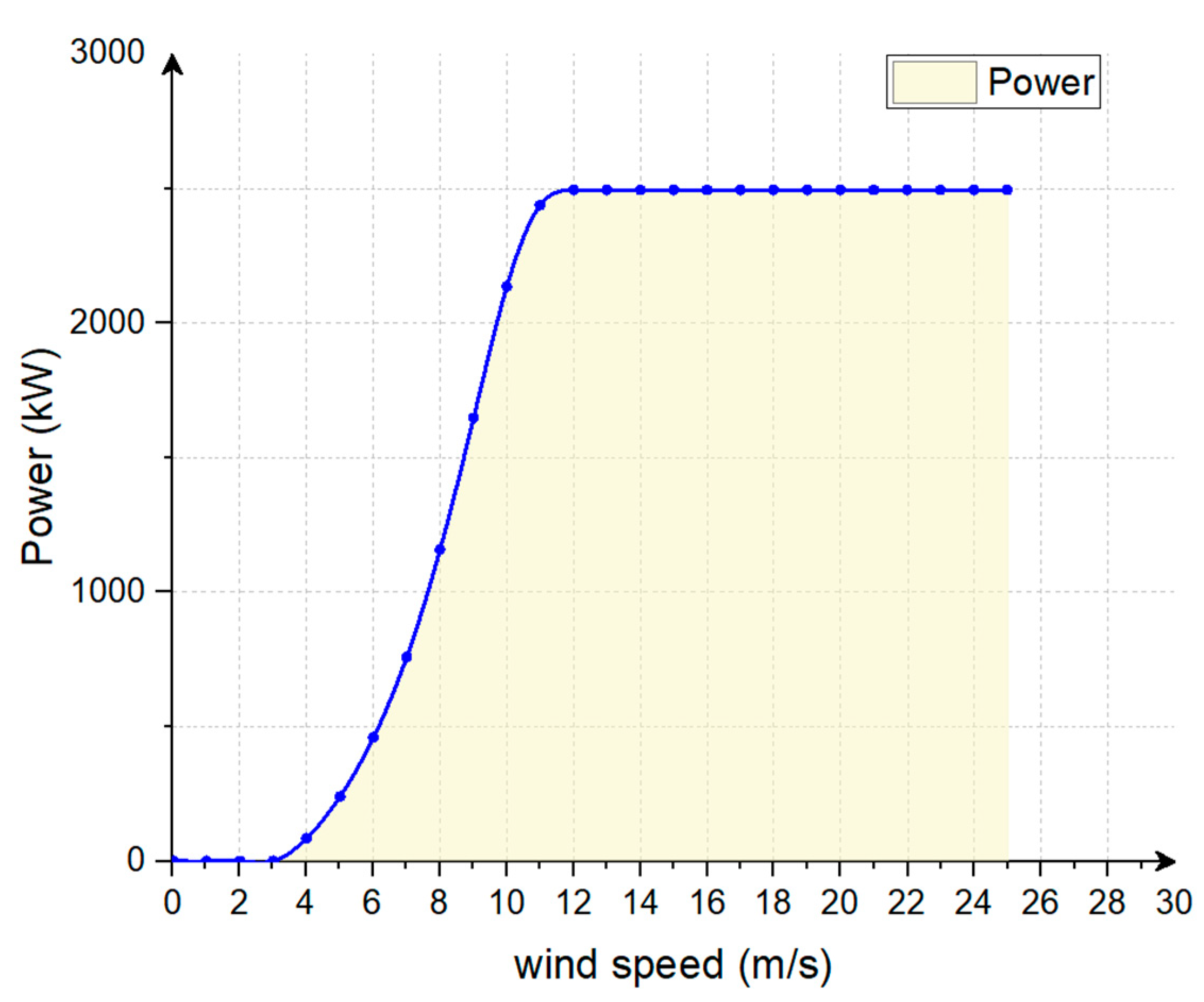
Figure 2 presents the power curve of a Fuhrländer FL 2500/104 wind turbine. At a wind speed below 10 m/s, the rotor operates at a sub-synchronous speed. At high wind speeds, it works at hyper-synchronous speeds. Another advantage of the asynchronous dual power generator technology is the ability of power electronic converters to generate or absorb reactive power, which eliminates the need to install capacitor batteries, as in the case of short circuit rotor asynchronous generators [
36,
37].
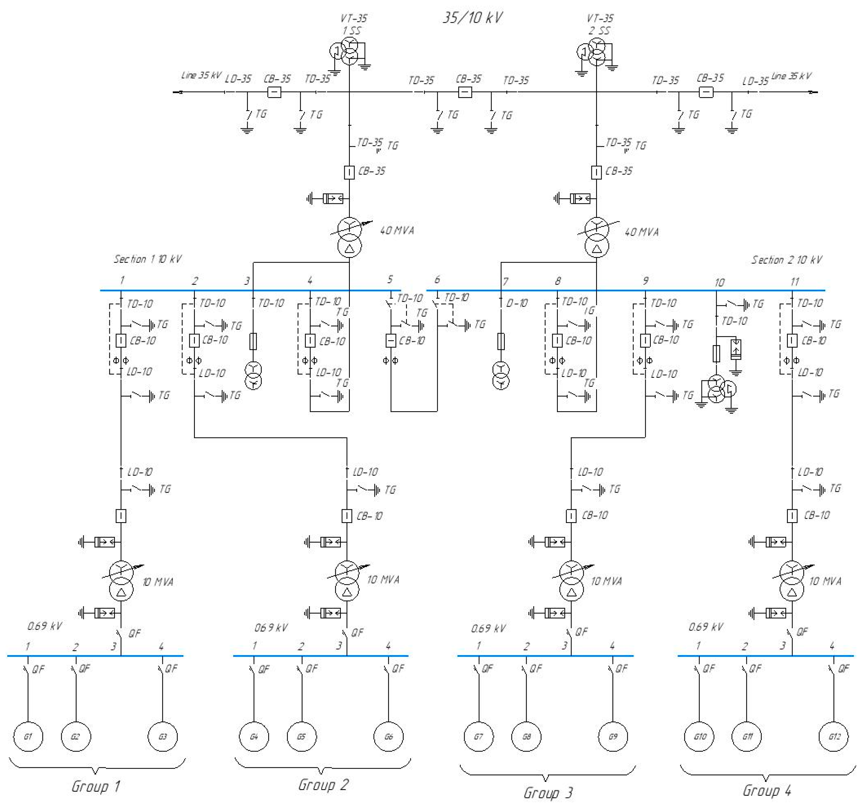
The wind farm system consists of wind power modules and a central substation, which allows the total power to be supplied to the power system at a voltage of 35 kV. The central substation uses 2 high voltage switchgears. When developing wind power modules, it was decided to use 4 modules, each of them consisting of 3 wind turbines; the power of 1 module was 7.5 MW. A 7.5 MW wind farm consisting of three wind turbines of 2.5 MW, connected to a 10.5 kV distribution system exporting electricity to the 35 kV grid. An installation with a voltage of 2300 V, a power of 1.01 MVA, consisting of an engine load (asynchronous motor capacity of 1 MW) and a resistive load of 10 kW, is connected to the buswork 10.5 kW. Both the wind turbines and the engine load have a system to control the voltage, current, and rotation speed of the rotor. The DC link generator voltage of the wind electric installation is also monitored. The general wind farm scheme is shown in
Figure 3.
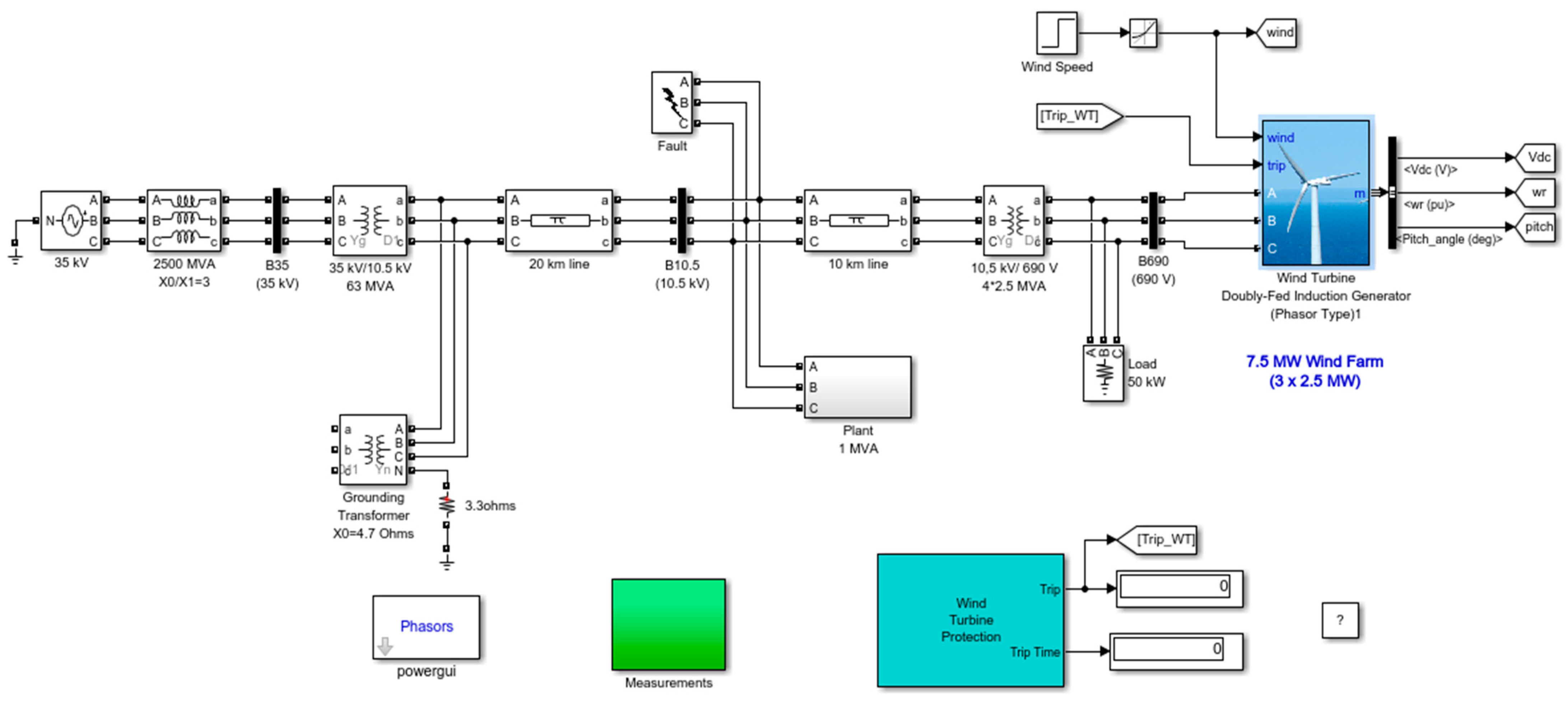
The 7.5 MW wind farm model developed in MATLAB
® Simulink
® is shown in
Figure 4. A general scheme of the wind power plant was developed using a modular-trunk power distribution scheme.
The wind turbine model is a vector model that enables long-term stability studies. In this example, the system is observed for 50 s.
A wind farm consisting of 3 wind turbines is modelled by 1 wind turbine unit by multiplying the following parameters by 3, as shown below:
In this study, we investigate the wind farm behavior for different cases:
Wind farm operation in Voltage regulation and AC regulation mode assuming a sudden wind speed change—initially, wind speed is set to 8 m/s; then, at t = 5 s, wind speed suddenly increases to 14 m/s;
Wind farm operation in Voltage regulation and AC adjustment mode assumes a sudden voltage drop—wind speed is constant and equal to 8 m/s, simulation time t = 50 s;
Wind farm operation in a single-phase short circuit on earth in a system of 10.5 kV. We assumed the short circuit time t = 5 s and its duration 5 + 9/60 s. Initially, wind speed is set to 8 m/s, then at t = 5 s wind speed suddenly increases to 14 m/s.
3. Research Results
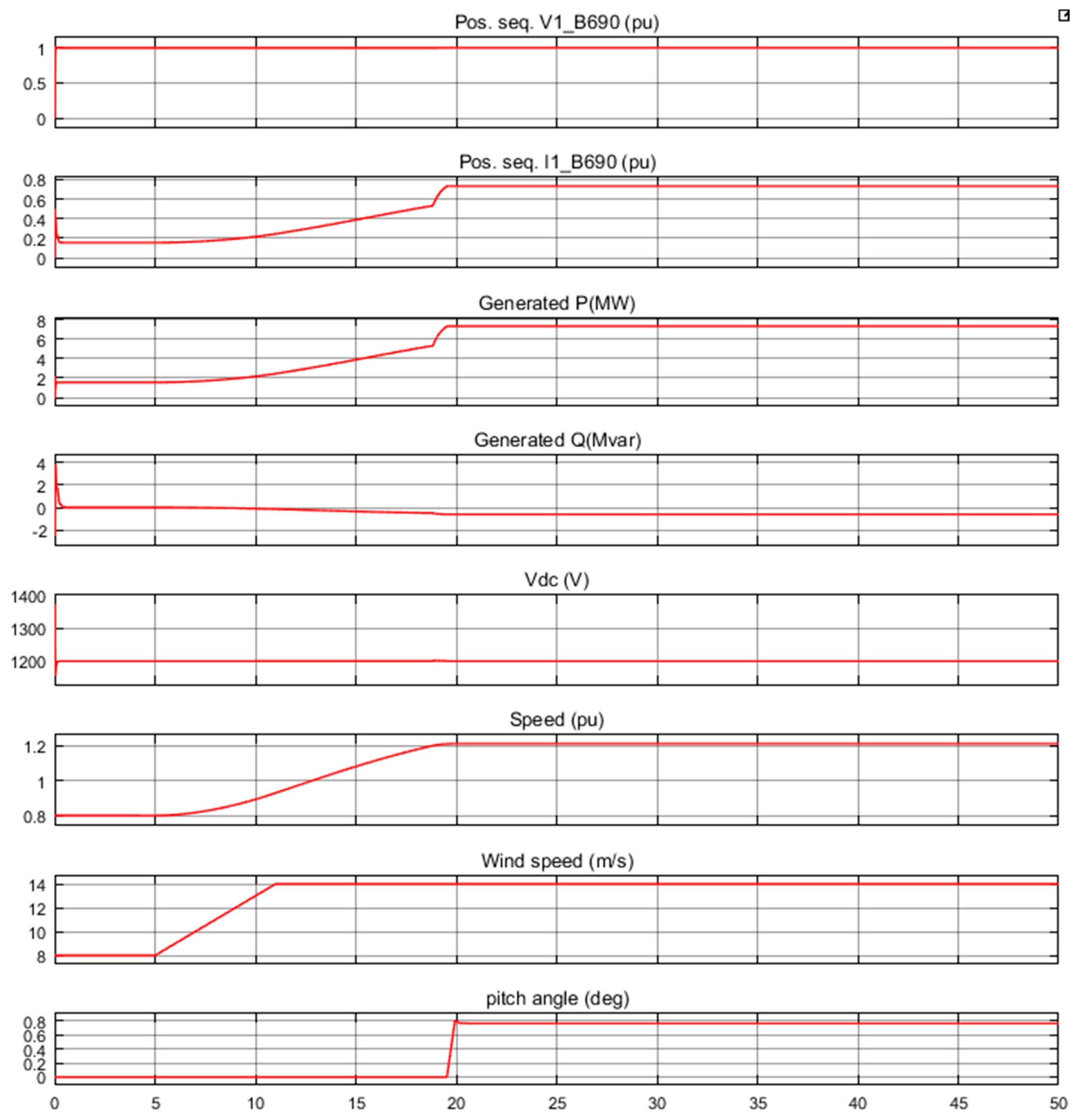
3.1. Simulation of Wind Farm Operation under Conditions of Sudden Wind Speed Change
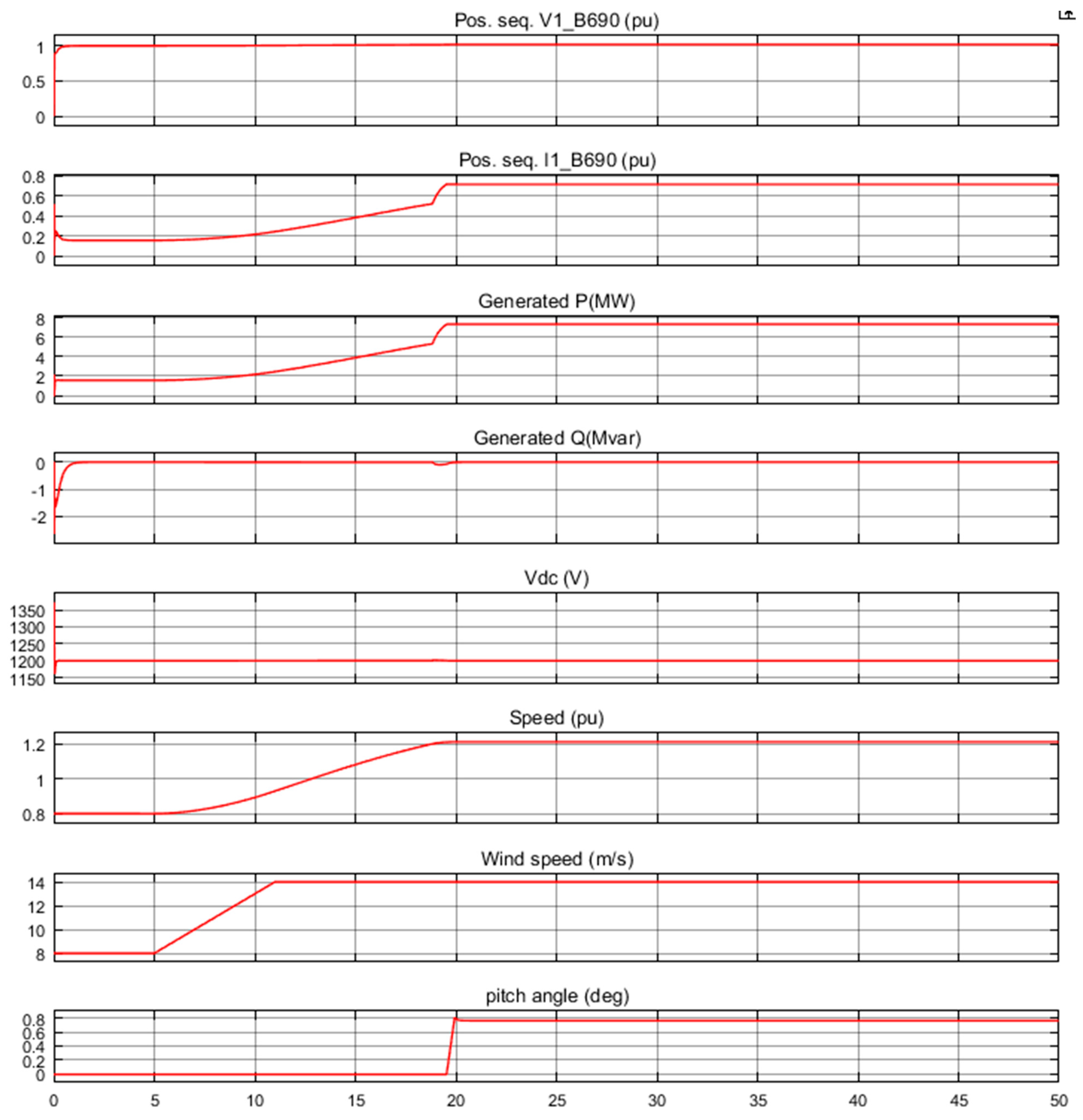
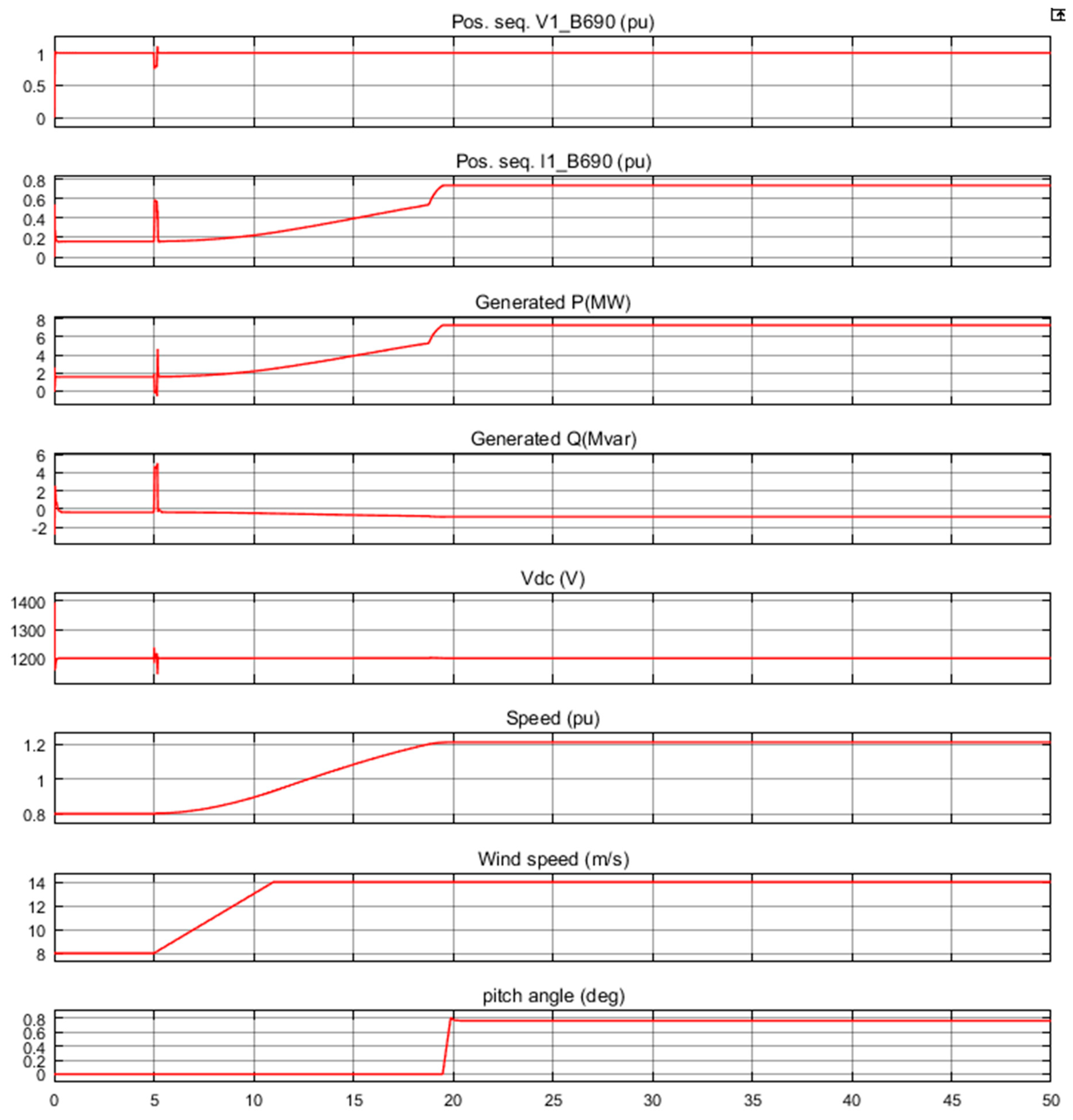
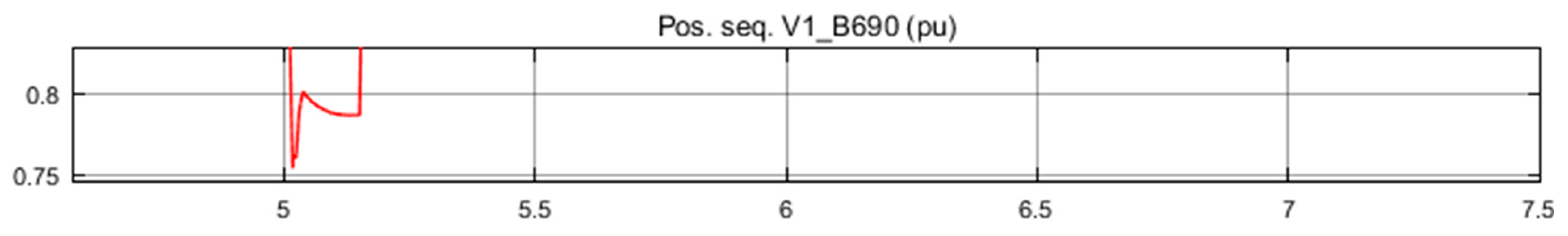
We performed a simulation of the wind speed change. Initially, the wind speed was set to 8 m/s; then, at t = 5 s, wind speed suddenly increased to 14 m/s. At the start of the simulation, an oscilloscope monitored the voltage, current, active and reactive power, DC bus voltage, and turbine speed. The results of the study “Voltage regulation” operation mode are shown in
Figure 5. At t = 5 s, the active power starts to increase gradually (together with the speed of the turbines), reaching its nominal value of 7.5 MW after about 18 s. During this time, the speed of the turbines will increase from 0.8 units to 1.21 units. Initially, the turbine blade inclination angle is zero, and the operating point of the turbine follows the red curve of the turbine power characteristics to point D. Then, the angle of inclination is increased from 0 to 0.76 degrees to limit the mechanical power. Reactive power is adjustable to maintain a voltage of 1 unit. At rated power, the wind turbine absorbs 0.6 MVar (Q = −0.6 MVar generated) to maintain a voltage of 1 unit.
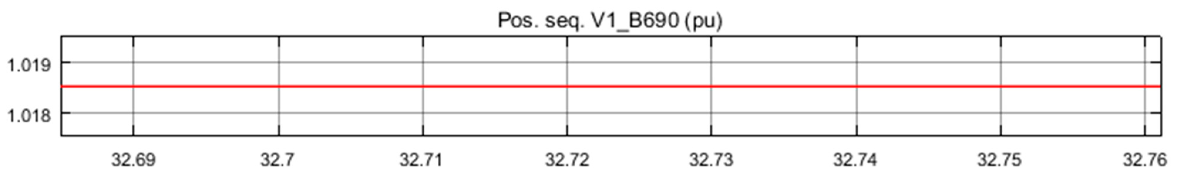
If one changes the mode to “AC” when “Qref Generating Reactive Power” is set to zero, one can see that the voltage rises to 1.0185 units when the wind turbine generates its rated power at a single power factor. The results of the study of wind turbine operation under “AC regulation” mode are shown in
Figure 6 and
Figure 7, respectively.
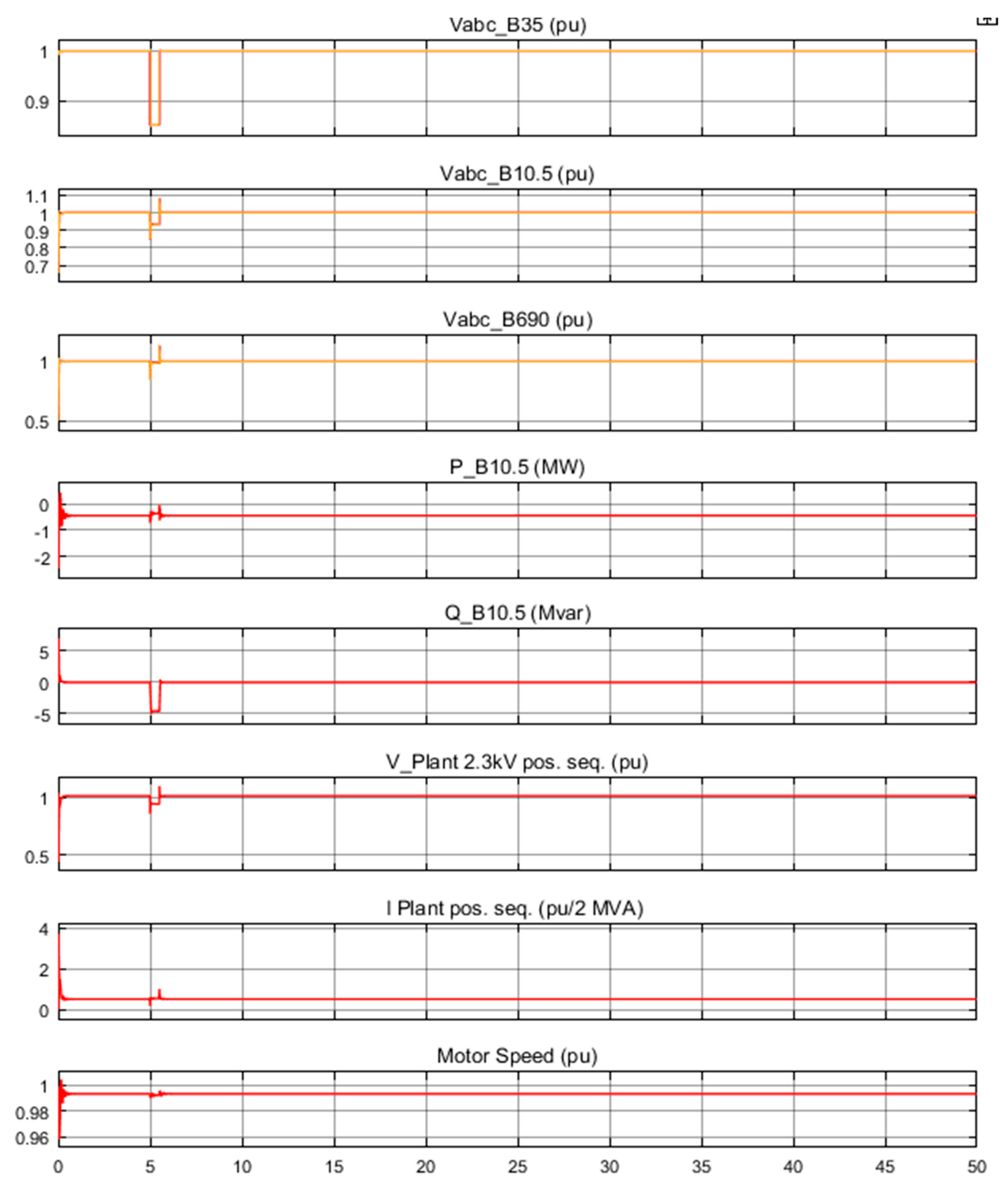
3.2. Simulation of Wind Farm Operation under Conditions of Sudden Voltage Drop
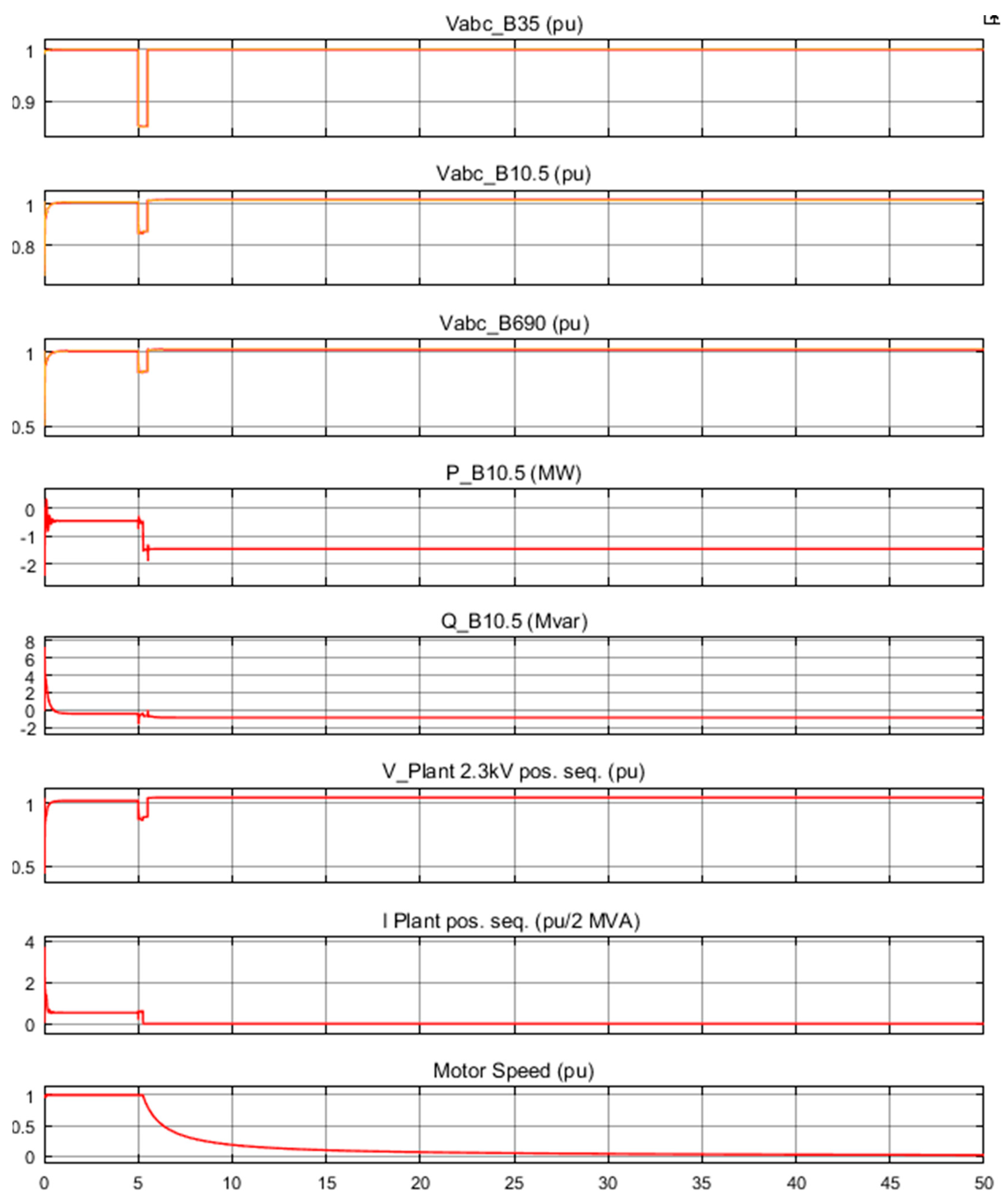
We then performed a simulation of the voltage drop in the system with a voltage of 35 kV. For a simulation of this mode, air speed was assumed to be constant throughout the simulation process t = 50 s, and equal to 8 m/s.
The first mode in which the simulation was conducted was “AC adjustment” operation mode when “Generating reactive power Q
ref” was zero. The simulation results are shown in
Figure 8, and the electric motor voltage when the voltage drops are shown in
Figure 9.
The characteristics of the wind power station operation for a voltage drop in the system of 35 kV for the WWP operation mode “AC adjustment” are shown in
Figure 10.
As can be seen in
Figure 8 and
Figure 9, the last three waveforms represent the voltage, current, and rotational speed of the rotor motor.
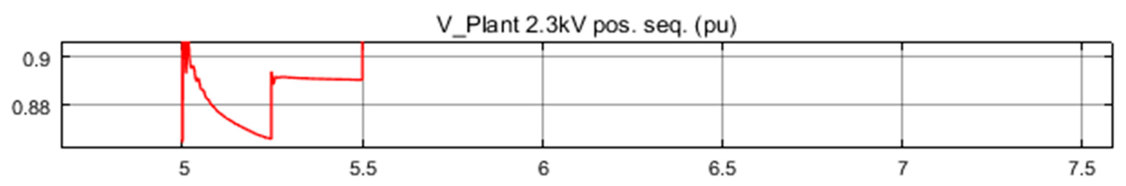
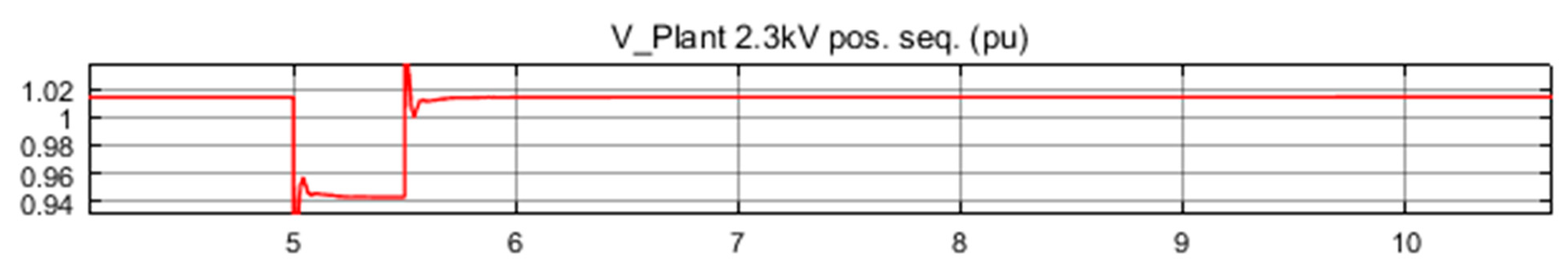
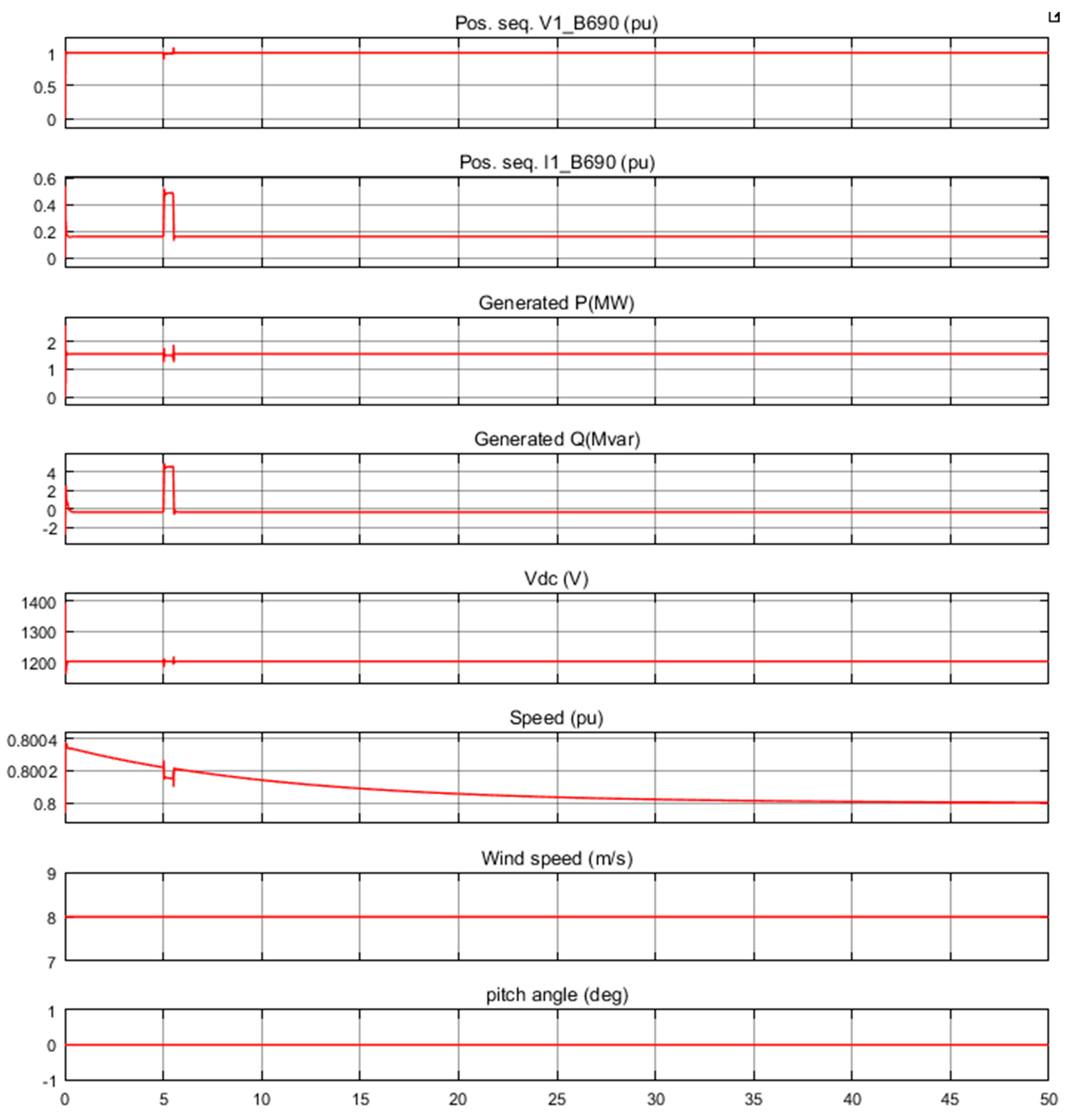
Figure 10 shows that the wind farm generates 1.55 MW of power. At t = 5 s, the voltage drops below 0.9 units, and at t = 5.22 s, the protection system shuts off the installation, as a reduced voltage of more than 0.2 s is detected (which is specified in the electric motor protection system). The electric motor current drops to zero and the engine speed gradually decreases, while the wind farm continues to generate energy at 1.55 MW. After the plant is shut down, 1.44 MW of power is exported to the electricity grid.
Next, the operating mode of the wind farm is changed to “Voltage regulation” and the simulation is repeated. The simulation results show that the electric motor is no longer shut off. This is due to the fact that the voltage supplied by the 5 MVar, the reactive power generated by wind turbines during the voltage drop, is sustained and maintains the installation voltage above the protection threshold of 0.9 units. The installation voltage during voltage drop is now 0.945 units. The motor response to the voltage drop in the 35 kV system for WPP “Voltage regulation” operation mode is presented in
Figure 11, and the voltage of the electric motor for a voltage drop is shown in
Figure 12.
The characteristics of the wind farm operation at a voltage drop in the system of 35 kV “Voltage regulation” mode are shown in
Figure 13.
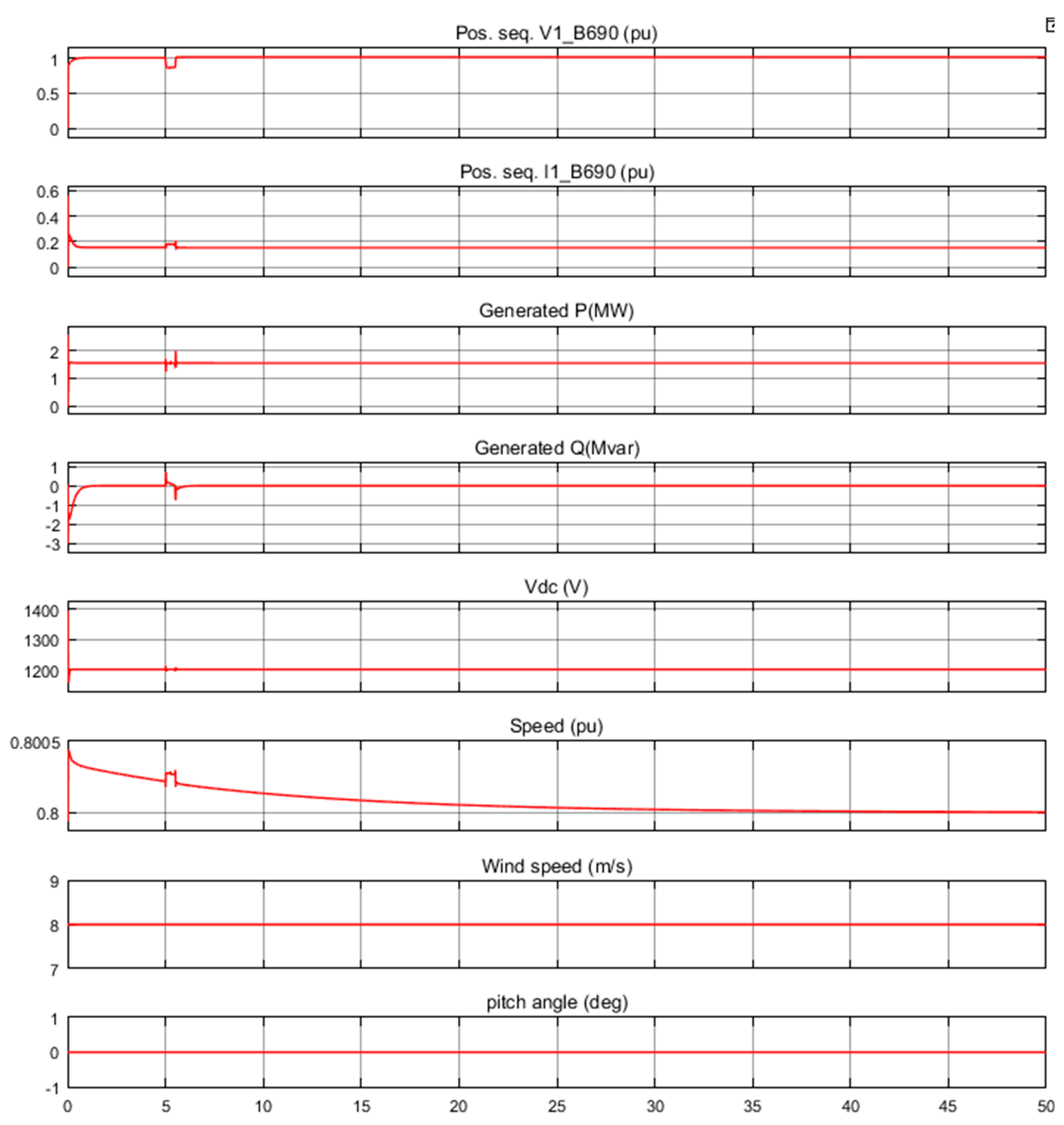
3.3. Simulation of Wind Farm Operation in Conditions of Single-Phase Short Circuit
We performed a simulation of a single-phase short circuit on earth in a system of 10.5 kV. The short circuit was programmed for time t = 5 s, duration 5 + 9/60 s.
At the beginning, the wind speed was set to 8 m/s; then, at t = 5 s, the wind speed increased to 14 m/s.
The first simulation of a single-phase short circuit in a system with a voltage of 10.5 kV was carried out at the operation mode of WPP “Voltage regulation”.
The simulation results of a single-phase short circuit to earth in a system of voltage 10.5 kV for “Voltage regulation” operation mode are shown in
Figure 14, while the wind farm output voltage value when modeling a single-phase short circuit to the earth in a system of voltage 10.5 kV for “Voltage regulation” operation mode is shown in
Figure 15.
4. Conclusions
In this article, modelling of operation modes for a wind power plant with an installed capacity of 30 MW was carried out. Twelve Fuhrländer FL 2500/104 wind turbines, with an installed capacity of 2.5 MW each, were selected for the wind farm. This was a wind farm of the variable rotational speed type equipped with an asynchronous doubly fed induction generator. When developing the main scheme of the wind power plant, it was decided to use a modular-trunk power distribution scheme. The central substation used: two high voltage switchgears; a 10 kV switchgear connected according to a “One single, sectioned by a circuit breaker, bus system” scheme, and a 35 kV switchgear connected according to a “Bridge with a switch in the transformer circuits and a repair jumper on the power line side” scheme.
For the development of wind power modules, it was proposed to use four modules, each including three wind turbines of 2.5 MW, respectively; the capacity of one module was 7.5 MW. Each wind turbine has its own independent transformer, with a natural circulation of oil and air, and with a voltage of 0.69/10.5 kV. Three voltage classes were used, 690 V, 10.5 kV, and 35 kV. An active load of 50 kW is connected to a voltage of 690 V and an asynchronous motor with a power of 1 MW is connected on the 10.5 kV side.
The aim of this study is to simulate emergency modes, as well as to show graphically the characteristics and transition processes that may arise at a wind farm. The simulation of three operation modes of wind turbines was carried out. The first was “Normal operation” mode. The operation of the wind turbines was set to the “Voltage regulation” mode. In the “Voltage regulation” operating mode, one can see that the wind turbines consume 0.6 MVar of reactive power from the network, thereby maintaining the nominal voltage at a level of 690 V. When the wind turbines operate in the “AC regulation” mode, one can see that the wind turbines already do not consume reactive power from the network, and the nominal voltage deviates by 2% from the nominal. The second operating mode is “Voltage drop in the 35 kV system”. The operation of the wind turbines is set to the “AC regulation” operating mode, and the wind speed is constant and equal to 8 m/s. As can be seen from the oscillograms—during 5 s—there is a voltage drop in the 35 kV system, lasting 0.5 s; thus, the voltage on the motor drops by almost 13%, and since the voltage drop lasts more than 0.2 s, the motor protection is triggered and is turned off. At this time, the wind farm continues to generate 1.5 MW of power into the grid. For the wind turbine operating in “Voltage regulation” mode, the engine is not switched off; at the moment of the voltage drop in the 35 kV system, the wind farm begins to generate reactive power, thereby preventing the voltage drop on the motor to less than 10%. Due to this, the motor remains in operation. At the same time, the wind farm generates 0.5 MW of power into the grid.
The third mode of operation is the simulation of a single-phase short circuit in a 10.5 kV system. For the wind farm in “Voltage regulation” operating mode, a short circuit occurs in the fifth second and the voltage at the terminals of the generators drops by 24%, while the generator shutdown is programmed for a voltage drop of more than 25% and if the duration exceeds 0.1 s. Thus, due to the generation of reactive power, the wind farm remains in operation. In the case of a similar simulation, but with the wind farm in “AC regulation” operation mode, the wind farm is turned off, as the voltage at the generator terminals drops by 33% and the duration exceeds 0.1 s.
The simulation results demonstrate in which permissible emergency modes a wind farm can continue to generate energy and in which it should disconnect. From the perspective of power generation, the most unfavorable conditions are sudden voltage drops, which will cause a reduction in power generation, both in AC regulation and Voltage regulation mode. In addition, energy production will be stopped when a short circuit occurs during AC regulation mode.
Author Contributions
Conceptualization, M.Z.Q., O.M., T.S. and R.K.; methodology, M.Z.Q., O.M., T.S., R.K., A.T. and M.Z.; software, M.Z.Q., O.M., T.S. and A.I.; validation, M.Z.Q., O.M., T.S., W.K. and K.D.; formal analysis, A.T., J.F., R.K., A.I., W.K., P.B.-W., M.Z. and K.D.; investigation, M.Z.Q., O.M., T.S., K.D., P.B.-W. and R.K.; resources, M.Z.Q., O.M., T.S., W.K., A.I. and M.Z.; data curation, M.Z.Q., O.M. and T.S.; writing—original draft preparation, M.Z.Q., O.M., T.S., R.K., A.I., W.K., A.T., J.F., P.B.-W., M.Z. and K.D.; writing—review and editing, M.Z.Q., O.M., T.S., R.K., A.I., W.K., A.T., J.F., P.B.-W., M.Z. and K.D.; visualization, M.Z.Q., O.M. and T.S.; supervision, A.T., J.F., R.K., A.I., W.K., P.B.-W., M.Z. and K.D.; funding acquisition, A.I. and M.Z. All authors have read and agreed to the published version of the manuscript.
Funding
The APC was funded by Częstochowa University of Technology.
Institutional Review Board Statement
Not applicable.
Informed Consent Statement
Not applicable.
Data Availability Statement
The data presented in this study are available on request from the authors.
Conflicts of Interest
The authors declare no conflict of interests.
References
- WWEA. Worldwide Wind Capacity Reaches 744 Gigawatts—An Unprecedented 93 Gigawatts Added in 2020. World Wind Energy Assoc. Available online: https://wwindea.org/worldwide-wind-capacity-reaches-744-gigawatts/ (accessed on 26 March 2021).
- Huber, M.; Dimkova, D.; Hamacher, T. Integration of Wind and Solar Power in Europe: Assessment of Flexibility Requirements. Energy 2014, 69, 236–246. [Google Scholar] [CrossRef]
- Nadour, M.; Essadki, A.; Nasser, T. Improving low-voltage ride-through capability of a multimegawatt DFIG based wind turbine under grid faults. Prot. Control. Mod. Power Syst. 2020, 5, 33. [Google Scholar] [CrossRef]
- Komada, P.; Trunova, I.; Miroshnyk, O.O.; Savchenko, O.A.; Shchur, T.G. The Incentive Scheme for Maintaining or Improving Power Supply Quality. Prz. Elektrotech. 2019, 95, 79–82. [Google Scholar] [CrossRef]
- Wang, L.; Wu, J.; Tang, Z.; Wang, T. An Integration Optimization Method for Power Collection Systems of Offshore Wind Farms. Energies 2019, 12, 3965. [Google Scholar] [CrossRef]
- Pantsyr, Y.; Garasymchuk, I.; Duganets, V.; Melnyk, M.; Yurchenko, O. Current State and Prospects of Wind Energy Development in Ukraine. E3S Web Conf. 2020, 154, 06004. [Google Scholar] [CrossRef]
- Evwind. Ukraine Will Benefit from Wind Energy but Policy Fixes Are Needed for a Quicker Expansion/REVE News of the Wind Sector in Spain and in the World. Available online: https://www.evwind.es/2021/04/24/ukraine-will-benefit-from-wind-energy-but-policy-fixes-are-needed-for-a-quicker-expansion/80482 (accessed on 5 May 2021).
- GKD 341.003.001.002-2000. Rules for Designing Wind Power Plants. 2000.
- González, J.S.; Payán, M.B.; Santos, J.M.R.; González-Longatt, F. A review and recent developments in the optimal wind-turbine micro-siting problem. Renew. Sustain. Energy Rev. 2014, 30, 133–144. [Google Scholar] [CrossRef]
- Miroshnyk, O.; Lukasik, Z.; Szafraniec, A.; Lezhniuk, P.; Kovalyshyn, S.; Shchur, T. Reducing the Dissymmetry of Load Currents in Electrical Networks 0,4/0,23 KV Using Artificial Neural Networks. Prz. Elektrotech. 2019, 1, 247–251. [Google Scholar] [CrossRef]
- Quinonez-Varela, G.; Ault, G.W.; Anaya-Lara, O.; McDonald, J.R. Electrical collector system options for large offshore wind farms. IET Renew. Power Gener. 2007, 1, 107–114. [Google Scholar] [CrossRef]
- Trunova, I.; Miroshnik, O.; Savchenko, O.; Moroz, O.; Pazyi, V.; Shchur, T.; Kasner, R.; Bałdowska-Witos, P. Scheduling of Preventive Maintenance of an Power Equipment of the Agricultural Enterprises. J. Phys. Conf. Ser. 2021, 1781, 012018. [Google Scholar] [CrossRef]
- Al_Issa, H.A.; Qawaqzeh, M.; Khasawneh, A.; Buinyi, R.; Bezruchko, V.; Miroshnyk, O. Correct Cross-Section of Cable Screen in a Medium Voltage Collector Network with Isolated Neutral of a Wind Power Plant. Energies 2021, 14, 3026. [Google Scholar] [CrossRef]
- Savchenko, O.A.; Miroshnyk, O.O.; Dubko, S.V.; Shchur, T.G.; Komada, P.; Mussabekov, K. Justification of Ice Melting Capacity on 6–10 kV OPL Distributing Power Networks Based on Fuzzy Modeling. Prz. Elektrotech. 2019, 95, 106–109. [Google Scholar] [CrossRef]
- Bałdowska-Witos, P.; Kruszelnicka, W.; Kasner, R.; Tomporowski, A.; Flizikowski, J.; Kłos, Z.; Piotrowska, K.; Markowska, K. Application of LCA Method for Assessment of Environmental Impacts of a Polylactide (PLA) Bottle Shaping. Polymers 2020, 12, 388. [Google Scholar] [CrossRef]
- Canbulat, S.; Balci, K.; Canbulat, O.; Bayram, I.S. Techno-Economic Analysis of On-Site Energy Storage Units to Mitigate Wind Energy Curtailment: A Case Study in Scotland. Energies 2021, 14, 1691. [Google Scholar] [CrossRef]
- Silva, J.E.; Danao, L.A.M. Varying VAWT Cluster Configuration and the Effect on Individual Rotor and Overall Cluster Performance. Energies 2021, 14, 1567. [Google Scholar] [CrossRef]
- Ju, X.; Liu, F. Wind farm layout optimization using self-informed genetic algorithm with information guided exploitation. Appl. Energy 2019, 248, 429–445. [Google Scholar] [CrossRef]
- Liu, F.; Ju, X.; Wang, N.; Wangg, L.; Leeh, W.-J. Wind farm macro-siting optimization with insightful bi-criteria identification and relocation mechanism in genetic algorithm. Energy Convers. Manag. 2020, 217, 112964. [Google Scholar] [CrossRef]
- Ju, X.; Liu, F.; Wang, L.; Lee, W.-J. Wind farm layout optimization based on support vector regression guided genetic algorithm with consideration of participation among landowners. Energy Convers. Manag. 2019, 196, 1267–1281. [Google Scholar] [CrossRef]
- Kasner, R.; Kruszelnicka, W.; Bałdowska-Witos, P.; Flizikowski, J.; Tomporowski, A. Sustainable Wind Power Plant Modernization. Energies 2020, 13, 1461. [Google Scholar] [CrossRef]
- Fantauzzi, M.; Lauria, D.; Mottola, F.; Proto, D. Estimating Wind Farm Transformers Rating through Lifetime Characterization Based on Stochastic Modeling of Wind Power. Energies 2021, 14, 1498. [Google Scholar] [CrossRef]
- González, J.S.; Rodríguez, A.G.G.; Mora, J.C.; Payána, M.B.; Santosa, J.R. Overall design optimization of wind farms. Renew. Energy 2011, 36, 1973–1982. [Google Scholar] [CrossRef]
- Modukpe, G.; Diei, D. Modeling and Simulation of a 10 KW Wind Energy in the Coastal Area of Southern Nigeria: Case of Ogoja; IntechOpen: London, UK, 2020; ISBN 978-1-78984-591-4. [Google Scholar]
- Cuesta, A.B.; Gomez-Gil, F.J.; Fraile, J.V.M.; Rodríguez, J.A.; Calvo, J.R.; Vara, J.P. Feasibility of a Simple Small Wind Turbine with Variable-Speed Regulation Made of Commercial Components. Energies 2013, 6, 3373–3391. [Google Scholar] [CrossRef]
- Baloch, M.; Campus, K.; Wattoo, A.; Kumar, D.; Kaloi, G.; Pakistan, S.; Memon, A.; Tahir, S.; Wattoo, W.A. Active and Reactive Power Control of a Variable Speed Wind Energy Conversion System Based on Cage Generator. Int. J. Adv. Comput. Sci. Appl. 2017, 8, 197–202. [Google Scholar] [CrossRef]
- Saheb-Koussa, D.; Haddadi, M.; Belhamel, M.; koussa, M.; noureddine, S. Modeling and Simulation of Windgenerator with Fixed Speed Wind Turbine under Matlab-Simulink. Energy Procedia 2012, 18, 701–708. [Google Scholar] [CrossRef]
- Nawaz, A. Simulation of Variable Speed Wind Turbine Voltage Regulation Model Using MATLAB/Simulink. Int. J. Eng. Adv. Technol. 2013, 2, 357–360. [Google Scholar]
- Jansuya, P.; Kumsuwan, Y. Design of MATLAB/Simulink Modeling of Fixed-Pitch Angle Wind Turbine Simulator. Energy Procedia 2013, 34, 362–370. [Google Scholar] [CrossRef]
- Qian, M.; Zhao, D.; Jiang, D.; Zhu, L.; Ma, J. Active and Reactive Power Control of Wind Farm Based on Integrated Platform of PowerFactory and MATLAB. In PowerFactory Applications for Power System Analysis; Gonzalez-Longatt, F.M., Luis Rueda, J., Eds.; Power Systems; Springer International Publishing: Cham, Switzerland, 2014; pp. 421–446. ISBN 978-3-319-12958-7. [Google Scholar]
- Mohammadpour, H.A.; Ghaderi, A.; Santi, E. Analysis of Sub-Synchronous Resonance in Doubly-Fed Induction Generator-Based Wind Farms Interfaced with Gate—Controlled Series Capacitor. IET Gener. Transm. Distrib. 2014, 8, 1998–2011. [Google Scholar] [CrossRef]
- Eriksson, S. Direct Driven Generators for Vertical Axis Wind Turbines; Acta Universitatis Uppsaliensis: Uppsala, Sweden, 2008. [Google Scholar]
- Bykov, E. Justification of the Parameters of a Wind Power Installation with Spiral Blades Based on Experimental Studies. Ph.D. Thesis, St. Petersburg State Polytechnical University, St. Petersburg, Russia, 2007. [Google Scholar]
- Klimina, L.A. The Vertical-Axis Wind Turbine: Dynamics and Control. Ph.D. Thesis, Moscow State University M.V. Lomonosova, Moscow, Russia, 2010. [Google Scholar]
- Belei, V.F.; Nikishin, A.Y. Calculation of electricity generation by wind power plants according to wind potential. In Electrical Equipment of Ships and Electric Power Industry: Collection. Scientific tr; Publishing House of KSTU: Kaliningrad, Russia, 2004; pp. 4–6. [Google Scholar]
- Burykin, O. Optimization of the Functioning of the Renewable Energy Sources in the Local Electrical Systems. Prz. Elektrotech. 2017, 1, 99–104. [Google Scholar] [CrossRef][Green Version]
- Gils, H.C.; Scholz, Y.; Pregger, T.; Luca de Tena, D.; Heide, D. Integrated Modelling of Variable Renewable Energy-Based Power Supply in Europe. Energy 2017, 123, 173–188. [Google Scholar] [CrossRef]
- Fuhrländer FL 2500/104—2, 50 MW—Wind Turbine. Available online: https://en.wind-turbine-models.com/turbines/1346-fuhrlaender-fl-2500-104 (accessed on 27 May 2021).
| Publisher’s Note: MDPI stays neutral with regard to jurisdictional claims in published maps and institutional affiliations. |
© 2021 by the authors. Licensee MDPI, Basel, Switzerland. This article is an open access article distributed under the terms and conditions of the Creative Commons Attribution (CC BY) license (https://creativecommons.org/licenses/by/4.0/).


 ,
, 


