Abstract
To protect a photovoltaic module from the hot spot effect more efficiently, an AC (alternating current) module that contains a module-level MPPT (maximum power point tracking) has been put forward. In this paper, operation states of shadowed solar cells and relevant bypass diodes were studied through MATLAB/Simulink tools, and a commercial PV module was used to reveal the temperature change when working at different LMPP (local maximum power point). Experiment results show that bypass diode can reduce power loss for the AC module to some extent but has a limited effect on protecting the AC module from the hot spot effect. Instead, it is more likely to form a local hot spot when the bypass diode turns on, and the worst shading condition for the AC module with bypass diode is about 46.5% during work states.
1. Introduction
Along with the accelerated industrialization process of photovoltaic technology, safety and reliability have been non-negligible factors alongside efficiency and cost, especially for rooftop photovoltaics and BIPV (building-integrated photovoltaics), which are related to life and property. According to the Module Failure Report of the Japanese Photovoltaic Society in 2010, hot spots account for a large proportion of factors that lead to module failure [1]. The hot spot effect is a phenomenon of partial heating caused by the current mismatch of series-connected PV modules. Many situations can induce current mismatch of the PV module, such as partial shading [2], subfissure, degradation, etc. [3], while partial shading is one of the most common cases. After prolonged focal heating, the temperature of the hot spot center may reach up to 150 °C, which can lead to salt melting for the grid line and even unrecoverable damage to the lattice of Si material [4,5]. Currently, the most used way to protect a PV module from the hot spot effect is to set a bypass diode parallel to a series of solar cells of the PV module. Additionally, up to now, the performance of the bypass diode has been highly improved with lower threshold voltage and lower power dissipation devices, such as the MOSFET (metal-oxide-semiconductor field-effect transisitor) [6], CBS (cool bypass switch) [7], or other bypass switches [8,9]. Even though the power loss of a partially shaded PV module is decreased as a benefit of the bypass diode, there are still many photovoltaic plants catching fire during practical applications [10,11].
To further reduce the effect of a hot spot made on a PV module, module-level MPPT (maximum power point tracking) was put forward [12]. A PV module with a module-level MPPT and inverter set on the rear, which allows it to supply AC (alternating current) power, is called an AC module [13,14]. Every AC module is an independent unit that only works at its GMPP (global maximum power point). A benefit of its independence is that the AC module is convenient to be used in small grid-connected PV-systems, such as rooftop photovoltaics and BIPV. On the other hand, the AC module can also reduce energy losses caused by mismatch and partial shading. The University of Texas Houston Health Science Center installed 20 AC modules as a PV window awning in 2000 [15]. In an AC module, the bypass diode and inverter are the main components, besides solar cells. To obtain the best effect on hot spot prevention and to match the bypass diode well with the AC module, learning the operation states of bypass diodes and shadowed solar cells during practical operation is necessary. Among the published papers, many studies focus on the effect of shadow making on conventional PV modules [16,17] or PV array [18,19]. They revealed that the I-V curve showed step type characteristics and the P-V curve showed multi-peak properties when the PV module or PV array works under partial shading condition. The special output characteristic of partially shadowed PV module and PV array hinders the MPPT in tracing a proper working point for the PV module and PV array. Gallardo-Saavedra [19] used a LT-SPICE simulator to learn the effect of partial shading on PV system and showed I-V curves under different shading conditions. Mahto [20] reconfigured the structure of the PV module to improve its performance, while Pendem [21,22] and Sangram [23] learned the topology of PV array that impact the maximum power generation capability under different partial shading conditions. Zheng [24] and Diaz-Dorado [25,26] conducted research on topology of bypass diode and showed that a bypass diode can improve the efficiency of a PV system, especially when the number of PV cells within a bypass diode is small. However, all of these studies learned from the conventional modules and assessed from the global I-V curve instead of the real working point of a PV module or array when discussing power generation or power loss [27]. Discussing energy generation or consumption of the PV module away from its operation points is not in accordance with practical applications.
With an eye to the operation states of shadowed solar cell and the relevant bypass diode (relevant bypass diode is the bypass diode that parallels with the solar cell string with the shadowed solar cell) under working conditions, this paper is aimed at the role of a bypass diode in protecting the AC module from the hot spot effect and revealing the worst shading condition for the AC module, which is not shown in the existing literature.
2. Materials and Methods
In this experiment, MATLAB/Simulink simulation tools were used to simulate a PV module formed by 60 series-connected solar cells, in which every 20 solar cells were placed parallel with one bypass diode (as shown in Figure 1a). Figure 1b is the simulation model used in this simulation experiment. In this model, the irradiance received by every solar cell can be controlled separately. Through modifying irradiance received by the solar cell, it is easy to realize the partial shading condition simulation of a PV module [2,28]. Normal irradiance is 1000 W/m2, while irradiance of the shadowed solar cell is set according to different shading ratios. The shading ratio used here is defined as the ratio of the irradiance received by shadowed solar cells to the irradiance received by solar cells without shadow [29]. With this simulation model, the current and terminal voltage of the shadowed solar cell (Issc, Vssc) and the relevant bypass diode (Ibd, Vbd) can be monitored synchronously during the simulation process of I-V characteristic. As the I-V characteristic curve shows all potential working points of the PV module, the monitoring curves of Issc, Vssc, Ibd, and Vbd during the I-V test process show the operational states of the shadowed solar cell and relevant bypass diode at all the working points of the PV module. Electrical parameters of the simulation module are shown in Table 1.
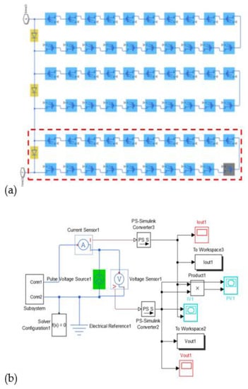
Figure 1.
Diagram of the simulated PV module structure and simulation model. (a) Schematic diagram of the simulated PV module (the icon with the blue background is the solar cell with normal irradiance, the icon with the gray background represents the shadowed solar cell, the icon with the yellow background is the bypass diode, and the red rectangle shows a solar cell string). (b) Diagram of simulation model.

Table 1.
Electrical parameters of PV module used in simulation experiment.
The commercial PV module used in the practical experiment is shown in Figure 2. There are 3 bypass diodes connected to the PV module. Each bypass diode is parallel with 20 solar cells. Parameters of the PV module used are shown in Table 2. To monitor the terminal voltage of the shadowed solar cell (the solar cell at the lower right corner of the PV module, shown in Figure 2) and relevant bypass diode, we set down-leads on both the anode and cathode of the solar cells arranged on the outermost array of the PV module. The experiment was conducted from 12:00 to 13:00 in Beijing when the irradiance is about 1000 W/m2. The partial shading condition was realized by using an opaque board to cover the target solar cell, and output characteristics of PV module were tested by a Keithley 2440 source meter. To make the PV module work at the LMPP (local maximum power point), we performed three steps. First, we tested the P-V characteristic curve of the PV module with a shading ratio of 20%. Second, we read out the voltage of the LMPPs of the PV module from its P-V curve in this shading condition. Third, we set the voltage obtained in the second step as the PV module’s output voltage. Up to now, the PV module will work at its LMPPs. Then, terminal voltage of the shadowed solar cell and relevant bypass diode can be tested at the working state. As the output power curve of a partially shaded PV module has multiple peaks, every LMPP has the potential to be the GMPP (global maximum power point) depending on different partial shading conditions. As a consequence, to discuss the actual work of an AC module in practice, we only need to consider the working conditions of the PV module, the shadowed solar cell, and the relevant bypass diode at every LMPP. PV module temperature was monitored by FOTRIC 255 IR imaging sensor.
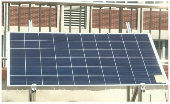
Figure 2.
Photo of the commercial PV module used in the practical experiment (the solar cell cover with a board at the bottom right corner of the module shows the shadowed solar cell).
Table 2.
Electrical parameters of the PV module used in temperature experiment.
3. Results
3.1. Operational States of Shadowed Solar Cell and Relevant Bypass Diode
Figure 3 shows the simulation result of the terminal voltage changing curves for the shadowed solar cell and relevant bypass diode (shading ratio is 50%). In the constant current zone of Step 1, the terminal voltage of the shadowed solar cell (Vssc) is reverse biased, and the Abs (absolute value) of the inverse voltage is approximately 11.7 V, while the terminal voltage of the relevant bypass diode (Vbd) is forward biased by 0.67 V, which reveals that the relevant bypass diode is in the ON state. With decreasing output current of the PV module, both Vssc and Vbd decrease until Vbd decreases to zero. In the Step 2 zone, the constant current is equal to the short circuit current of the shadowed solar cell (Issc). When the operating point of the PV module is in the constant current region of Step 2, i.e., the output current of the PV module (Iout) equals the Issc, Vssc decreases gradually with increasing output voltage of the whole module (Vout). At the same time, Vbd changes into reverse biased, and the voltage value increases simultaneously, which means that the relevant bypass diode is in the OFF state. With a decreasing Iout, Vssc turns into a forward bias, and the voltage value increases to the amount of the open-circuit voltage (Voc) of a solar cell (approximately 0.61 V). In the meantime, Vbd is stabilized at −11.6 V, which is roughly equal to the sum of the Voc of 20 solar cells.
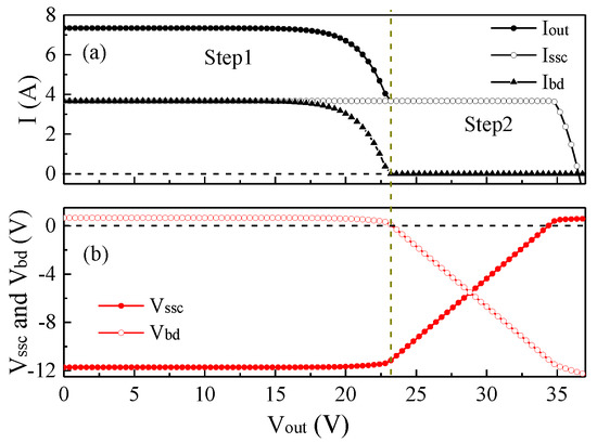
Figure 3.
Output characteristics of the simulated PV module with a shading ratio of 50%. (a) Current of the simulated module (black dotted line), the shadowed solar cell (black circle line) and relevant bypass diode (black triangle line). (b) Terminal voltage of the shadowed solar cell (red circle line) and relevant bypass diode along with the I-V test (red dotted line).
According to Figure 3, in the Step 1 zone, the bypass diode parallels with the solar cell string that including the partially shadowed solar cell remains to be ON [30]. This means the bypass diode protects the output current and power generation of the whole module from the impact of partial shading when the PV module works in the Step 1 zone. However, the shadowed solar cell continuously operates under a large reverse bias to consume energy in the Step 1 zone, which tends to raise the temperature of the shadowed solar cell. In the Step 2 zone, the relevant bypass diode stays in the OFF state, which means that the bypass diode is not protective, even though the PV module is partially shaded. The reversed terminal voltage of the shadowed solar cell gradually decreases (the power consumed by the shadowed solar cell is reduced too) until it is forward biased to generate electricity. That is, when the bypass diode turns on, the shadowed solar cell will consume more power and may generate more heat.
3.2. The Role of the Bypass Diode in an AC Module
Generally, a common PV module includes three bypass diodes which separate solar cells into three solar cell strings. If there is one solar cell string affected by shadow or two solar cell strings equally affected, the output I-V curves will have two steps at most, and P-V curves will have two LMPPs at most, as shown in Figure 4a and Figure 5a. If two or three solar cell strings are affected by shadows with different degrees, the I-V curves will have three steps at most, and the P-V curves will have three LMPPs at most, as shown in Supplementary Materials. When a module works at different LMPPs, the bypass diode plays different roles and has different effects on the module.
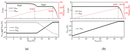
Figure 4.
Output characteristics of the simulated PV module, and the terminal voltages of the shadowed solar cell and relevant bypass diode when a solar cell receives a shadow across 20% of its area: (a) module with bypass diode, (b) module without bypass diode.
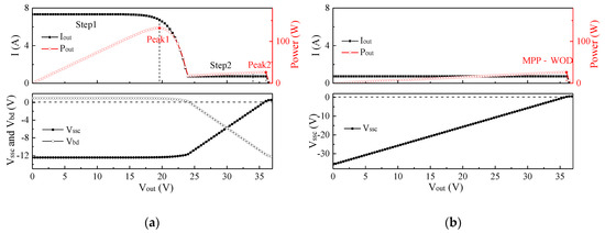
Figure 5.
Output characteristics of the simulated PV module, and the terminal voltages of the shadowed solar cell and relevant bypass diode when a solar cell receives a shadow across 90% of its area: (a) module with bypass diode, (b) module without bypass diode.
For the case of two LMPPs in the P-V curves of the PV module, we set a shading ratio of 20% for a certain solar cell as an example in the simulation. The output characteristics and terminal voltages of the shadowed solar cell and relevant bypass diode are shown in Figure 4a and Table 3. From left to right in the direction of increasing voltage, we named the two LMPPs as “Peak 1” and “Peak 2”, respectively. When the PV module works at the working point of Peak 1, the bypass diode that lies parallel with the partially shadowed solar cell string breaks over. At this moment, Vssc is approximately −10.79 V, and the power consumption of the shadowed solar cell is approximately 63.34 W. When the PV module works at the working point of Peak 2, the bypass diode that lies parallel with the partially shadowed solar cell string is cut off, Vssc is forward biased, and the power generation of the shadowed solar cell is approximately 2.44 W. Because the output power of Peak 1 (135.69 W) is smaller than that of Peak 2 (190.66 W), the PV module prefers to operate at the working point of Peak 2 under the action of module-level MPPT. At this condition, the bypass diode is OFF, while the shadowed solar cell is in the normal state of power generation. For the same shadow case with no bypass diode in the PV module, the output characteristics are shown in Figure 4b and Table 3 (the row of “MPP-WOD”). The MPP of the PV module without bypass diode is the same as the GMPP in the case including the bypass diode. If the PV module with no bypass diode works at the MPP, the shadowed solar cell will be forward biased, meaning that the shadowed solar cell will not be heated up through power consumption.
Table 3.
Parameters of the shadowed solar cell and the simulated PV module with a solar cell that has a shadow ratio of 20%.
When the shading ratio received by the shadowed solar cell is 90%, the output characteristics of the PV module and operational states of the shadowed solar cell and the relevant bypass diode are shown in Figure 5a. Unlike the condition of a 20% shading ratio, the GMPP of the system is Peak 1 when the PV module has a 90% shading ratio. According to Figure 5a, at the working point of GMPP, the bypass diode is ON, and Vssc is approximately −12.40 V, which results in power consumption of 9.05 W. If there is no bypass diode in the PV module, the MPP under this shading condition is the same as Peak 2 of the PV module with a bypass diode, as shown in Figure 5b. At the working point of Peak 2, the bypass diode is in the OFF state, and the output current of the PV module is in accordance with the output current of the shadowed solar cell (Iout = Issc). In common sense, the absence of the bypass diode would lead to the shadowed solar cell withstanding application of a reverse voltage due to the sum of the open-circuit voltages of all the other normal illuminated solar cells of the PV module, thus generating a large amount of heat. At the working point of Peak 2, the shadowed solar cell is forward biased, consumes no power, and produces no local temperature. However, the output power of the PV module is significantly decreased to 26.35 W, as shown in Table 4. Therefore, the bypass diode is useful for reducing the power loss in the PV module induced by partial shading to some extent but has a limited effect for protecting the PV module from a local hot spot.
Table 4.
Parameters of the shadowed solar cell and the simulated PV module with a solar cell that has a shadow ratio of 90%.
3.3. Temperature Change of PV Module at Different LMPPs
The commercial PV module used in this experiment is shown in Figure 2. The solar cell set at the right bottom corner of the module is the shadowed solar cell with a shading ratio of 20%. Parameters of Peak1 and Peak2 of the PV module are shown in Table 4. We set the output voltage of the PV module as 17.35 V, then the module will work at Peak 1. In the same way, the module will work at Peak 2 if we set its output voltage as 28.78 V. Temperatures were monitored with an infrared camera when the PV module worked at Peak 1 and Peak 2 for 0 min, 1 min, 10 min and 30 min. IR images are shown in Figure 6. Sp1 is the temperature of solar cells with normal irradiance, and SP2 shows the temperature of the partially shadowed solar cell.
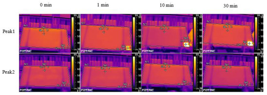
Figure 6.
IR image of the PV module when working at the LMPPs (SP1 is the temperature of the solar cell with normal irradiance, SP2 is the temperature of the shadowed solar cell).
As we can see from Figure 6, the temperature of the PV module is relatively uniform without shadings. When the PV module works at Peak 1, the temperature of the shadowed solar cell shows a rapid increase in 1 min. With the shading time prolonged, the temperature of the shadowed solar cell reaches up to 120 °C, about 70 °C higher than that of normal cells [31]. However, if the PV module works at Peak 2, the temperature of the shadowed solar cell shows little change. Instead, the shadowed solar cell’s temperature exhibits a tiny decrease due to the shielding effect of the opaque cardboard which shields the solar cell from direct sunlight. Figure 7 clearly shows the temperature change of the shadowed solar cell when working at different working points. With the extension of shading time, the temperature of the solar cell with normal irradiance keeps almost at a constant level, while the temperature of the shadowed solar cell has a sharp rise in 10 min and then tends to slow growth after 20 min when the PV module works at Peak 1. With longer time, there are high odds of a focal point forming at the shadowed solar cell [32]. Considering the terminal voltage of the shadowed solar cell (−9.35 V, as shown in Table 4) and relevant bypass diode (0.268 V) in this working point, it is easy to conclude that the bypass diode’s work gives more opportunity for the shadowed solar cell to form a hot spot. On the contrary, when working at Peak 2, the shadowed solar cell is forward biased (as shown in Table 5) and the temperature of the shadowed solar cell has no increase. This means that the shadowed solar cell consumes no power even though the bypass diode is OFF.
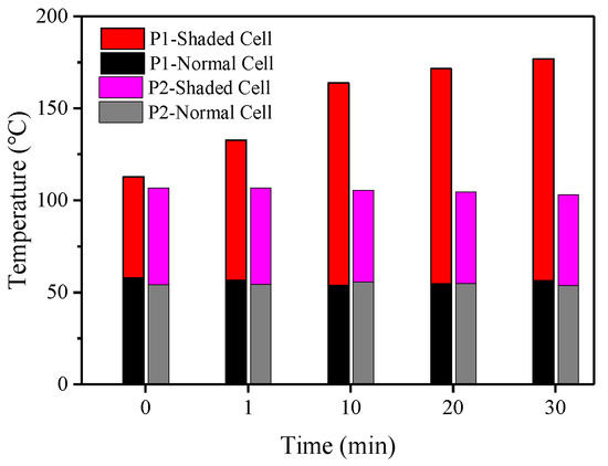
Figure 7.
Temperature change with shading time for the PV module at different working points (The temperatures reported in the figure are read from the IR camera images in Figure 6. Temperature of normal cell and shaded cell correspond to SP1 and SP2, respectively. P1 and P2 in the legend refer to Peak 1 and Peak 2).
Table 5.
Terminal voltage of the shadowed solar cell and relevant bypass diode at different working points.
3.4. The Worst Shading Ratio
With Matlab simulator, we simulated the output power of the PV module and the shaded solar cell when working at Peak 1 and Peak 2 separately under different shading ratios, as shown in Figure 8. As we can see from Figure 8a, if working at Peak 1, the output power of the PV module is almost unchanged with the increase in the shading ratio. On the contrary, the output power of the PV module decreases with the increase in the shading ratio. At the shading ratio of about 46.5%, the output power of the PV module working at Peak 1 is equal to the output power when working at Peak 2. Under the influence of module MPPT, the shading ratio of 46.5% is the turning point of GMPP. That is to say, when the shading ratio is lower than 46.5%, Peak 2 is the GMPP; when the shading ratio is higher than 46.5%, Peak 1 is the GMPP. However, the power of the shaded solar cell shows a different variation trend. When the PV module works at Peak 1, the shaded solar cell keeps consuming power, and power consumption decreases with the increase in the shading ratio. It is the case that the lower the shading ratio, the higher the power consumption. However, when the module works at Peak 2, the shaded solar cell is outputting power, and the power output remains the same.
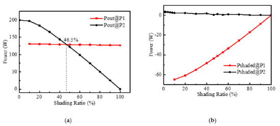
Figure 8.
Output power of PV module (a) and shadowed solar cell (b) when the module is working at Peak 1 and Peak 2 separately with different shading ratios.
Therefore, when the shading ratio is lower than 46.5%, the PV module works at Peak 2, the shaded solar cell outputs power, and there is no risk of forming a hot spot. When the shading ratio is higher than 46.5%, the PV module works at Peak 1, the shaded solar cell consumes power, and power-consuming decreases with shading ratio increase. Therefore, the shading ratio that is slightly larger than 46.5% is the worst shading condition.
As every AC module is controlled by MPPT independently, almost all of them can work at their GMPP. If without a bypass diode, there is no effect on the AC module when the shading ratio lower than 46.5%. When the shading ratio higher than 46.5%, there will be a negtive effect on the AC module. The negative effect only apply to one module rather than on the whole module string as appearing in the conventional PV array (constitute by DC modules).
4. Conclusions
Operation states of shadowed solar cells and relevant bypass diodes have been studied during working states of the PV module. The experimental results reveal that the operating point of the PV module is the other important factor influencing the bypass diode’s activation, besides shading condition. Due to the role of module-level MPPT, the working point of AC modules is only affected by their GMPP. Considering the multi-peak phenomena in the P-V curves for the PV module under partial shading condition, all bypass diodes are OFF at the last LMPP (from left to right in the direction of increasing output voltage in the P-V curve), while one or more bypass diodes turn on at the other LMPPs. What is more, when the bypass diode is ON, the shadowed solar cell works under a large reverse bias (for a commercial PV module, the reverse bias is approximately −12 V), which is liable to form local heating at the position of the shadowed solar cell. However, if the bypass diode is OFF, the paralleled shadowed solar cell will work at the forward biased condition, with no hot spot appearing at the position of the shadowed solar cell.
In addition, the power consumption of shadowed solar has a negative relationship with the shading ratio when the PV module works at Peak 1. For the AC module, which is always working at GMPP, the shading ratio of 46.5% is the worst shading condition. Therefore, we should particularly pay attention to the shadows which are about half the area of the PV module, for example, the shadow of leaves and branches. According to the shading condition of the installation site, we can decide to use a bypass diode or not. On the other hand, a better way to protect from the hot spot effect is to decrease the number of solar cells that are protected by one bypass diode to decrease the reverse bias applied to the shadowed solar cell due to the turning on of the bypass diode; this may be a better choice to effectively protect a PV module from a hot spot.
Supplementary Materials
The following are available online at https://www.mdpi.com/article/10.3390/en14164778/s1, Figure S1: Output characteristics of the simulated PV module, and the terminal voltages of the shadowed solar cell and relevant bypass diode when two solar cell strings receive different shading conditions. (a) module with bypass diode, (b) module without bypass diode. Table S1: Parameters for the shadowed solar cell and the simulated PV module when two solar cell strings receive different shading conditions.
Author Contributions
Conceptualization, H.R. and P.H.; methodology, H.R.; software, H.R.; validation, H.R. and P.H.; formal analysis, H.R.; investigation, H.R.; resources, H.R.; data curation, H.R.; writing—original draft preparation, R.H; writing—review and editing, H.R.; visualization, H.R.; supervision, P.H.; project administration, P.H.; funding acquisition, P.H. Both authors have read and agreed to the published version of the manuscript.
Funding
This research was funded by SCIENCE and TECHNOLOGY MINISTRY OF CHINA, grant number 2018YFB1500500.
Acknowledgments
We thank Baoding Lightway Green Energy Technology Co. Ltd for their support with experimental devices.
Conflicts of Interest
The authors declare no conflict of interest. The funders had no role in the design of the study; in the collection, analyses, or interpretation of data; in the writing of the manuscript, or in the decision to publish the results.
Abbreviations
| Isc | Short circuit current |
| Iout | Output current of PV module |
| Issc | The current of the shadowed solar cell |
| Ibd | The current of bypass diode |
| Voc | Open circuit voltage |
| Vout | The output current of PV module |
| Vssc | The voltage of the shadowed solar cell |
| Vbd | The voltage of bypass diode |
| Pout | The output power of PV module |
| MPP | Maximum Power Point |
| MPPT | Maximum Power Point Tracking |
| LMPP | Local Maximum Power Point |
| GMPP | Global Maximum Power Point |
| Abs | Absolute value |
| BIPV | Building-integrated photovoltaics |
| WOD | Without bypass diode |
| MPP-WOD | Maximum power point of PV module without bypass diode |
| MOSFET | metal-oxide-semiconductor field-effect transisitor |
| CBS | cool bypass switch |
References
- Yasushi, O.; Sanshiro, Y.; Daisuke, I. An investigation into hot-spot in PV module. Proc. Jpn. Sol. Energy 2010, 535–538. [Google Scholar]
- Fialho, L.; Melicio, R.; Mendes, V.M.F.; Figueiredo, J.; Collares-Pereira, M. Effect of Shading on Series Solar Modules: Simulation and Experimental Results. Procedia Technol. 2014, 17, 295–302. [Google Scholar] [CrossRef]
- Herrmann, W.; Wiesner, W.; Vaassen, W. Hot spot investigations on PV modules-new concepts for a test standard and consequences for module design with respect to bypass diodes. In Proceedings of the Photovoltaic Specialists Conference, Anaheim, CA, USA, 29 September–3 October 1997; pp. 1129–1132. [Google Scholar]
- Simon, M.; Meyer, E.L. Detection and analysis of hot-spot formation in solar cells. Sol. Energy Mater. Sol. Cells 2010, 94, 106–113. [Google Scholar] [CrossRef]
- Solheim, H.J.; Fjær, H.G.; Sørheim, E.A.; Foss, S.E. Measurement and Simulation of Hot Spots in Solar Cells. Energy Procedia 2013, 38, 183–189. [Google Scholar] [CrossRef][Green Version]
- Bauwens, P.; Doutreloigne, J. NMOS-Based Integrated Modular Bypass for Use in Solar Systems (NIMBUS): Intelligent Bypass for Reducing Partial Shading Power Loss in Solar Panel Applications. Energies 2016, 9, 450. [Google Scholar] [CrossRef]
- Acciari, G.; Graci, D.; La Scala, A. Higher PV Module Efficiency by a Novel CBS Bypass. IEEE Trans. Power Electron. 2011, 26, 1333–1336. [Google Scholar] [CrossRef]
- Daliento, S.; Di Napoli, F.; Guerriero, P.; d’Alessandro, V. A modified bypass circuit for improved hot spot reliability of solar panels subject to partial shading. Sol. Energy 2016, 134, 211–218. [Google Scholar] [CrossRef]
- Guerriero, P.; Tricoli, P.; Daliento, S. A bypass circuit for avoiding the hot spot in PV modules. Sol. Energy 2019, 181, 430–438. [Google Scholar] [CrossRef]
- Pandian, A.; Bansal, K.; Thiruvadigal, D.J.; Sakthivel, S. Fire Hazards and Overheating Caused by Shading Faults on Photo Voltaic Solar Panel. Fire Technol. 2015, 52, 349–364. [Google Scholar] [CrossRef]
- Wu, Z.; Hu, Y.; Wen, J.X.; Zhou, F.; Ye, X. A Review for Solar Panel Fire Accident Prevention in Large-Scale PV Applications. IEEE Access 2020, 8, 132466–132480. [Google Scholar] [CrossRef]
- Dunselman, C.P.M. Feasibility and developmen of PV modules with Integrated Inverter: AC modules. In Proceedings of the Twelfth European Photovoltaic Solar Energy Conference: Proceedings of the International Conference, Amsterdam, The Netherlands, 11–15 April 1994; pp. 313–415. [Google Scholar]
- De Graaf, L.E.; van de Weiden, T.C.J. Characteristics and performance of a pv-system consisting of 20 ac-modules. In Proceedings of the World Conference on Photovoltaic Energy Conversion, Waikoloa, HI, USA, 5–9 December 1994. [Google Scholar]
- Oldenkamp, H.; Jong, I.J.d. AC modules_ past, present and future. In Proceedings of the Workshop Installing the Solar Solution, Hatfield, UK, 22–23 January 1998. [Google Scholar]
- Hoffner, J.E.; Palani, M.M.; Russell, M.C. A PV window awning system on the University of Texas Houston Health Science Center using AC-modules. In Proceedings of the Twenty-Eighth IEEE Photovoltaic Specialists Conference—2000 (Cat. No.00CH37036), Anchorage, AK, USA, 15–22 September 2000; pp. 1545–1547. [Google Scholar]
- Kawamura, H.; Naka, K.; Yonekura, N.; Yamanaka, S.; Kawamura, H.; Ohno, H.; Naito, K. Simulation of I–V characteristics of a PV module with shaded PV cells. Sol. Energy Mater. Sol. Cells 2003, 75, 613–621. [Google Scholar] [CrossRef]
- Silvestre, S.; Chouder, A. Effects of shadowing on photovoltaic module performance. Prog. Photovolt. Res. Appl. 2008, 16, 141–149. [Google Scholar] [CrossRef]
- Patel, H.; Agarwal, V. MATLAB-Based Modeling to Study the Effects of Partial Shading on PV Array Characteristics. IEEE Trans. Energy Convers. 2008, 23, 302–310. [Google Scholar] [CrossRef]
- Gallardo-Saavedra, S.; Karlsson, B. Simulation, validation and analysis of shading effects on a PV system. Sol. Energy 2018, 170, 828–839. [Google Scholar] [CrossRef]
- Mahto, R.V.; Sharma, D.K.; Xavier, D.X.; Raghavan, R.N. Improving performance of photovoltaic panel by reconfigurability in partial shading condition. J. Photonics Energy 2020, 10, 1–15. [Google Scholar] [CrossRef]
- Pendem, S.R.; Mikkili, S. Modeling, simulation and performance analysis of solar PV array configurations (Series, Series–Parallel and Honey-Comb) to extract maximum power under Partial Shading Conditions. Energy Rep. 2018, 4, 274–287. [Google Scholar] [CrossRef]
- Pendem, S.R.; Mikkili, S. Modelling and performance assessment of PV array topologies under partial shading conditions to mitigate the mismatching power losses. Sol. Energy 2018, 160, 303–321. [Google Scholar] [CrossRef]
- Bana, S.; Saini, R.P. Experimental investigation on power output of different photovoltaic array configurations under uniform and partial shading scenarios. Energy 2017, 127, 438–453. [Google Scholar] [CrossRef]
- Zheng, H.; Li, S.; Challoo, R.; Proano, J. Shading and bypass diode impacts to energy extraction of PV arrays under different converter configurations. Renew. Energy 2014, 68, 58–66. [Google Scholar] [CrossRef]
- Diaz-Dorado, E.; Suárez-García, A.; Carrillo, C.; Cidras, J. Influence of the shadows in photovoltaic systems with different configurations of bypass diodes. In Proceedings of the International Symposium on Power Electronics, Electrical Drives, Automation and Motion, Pisa, Italy, 14–16 June 2010. [Google Scholar]
- Díaz-Dorado, E.; Cidrás, J.; Carrillo, C. Discretized model for partially shaded PV arrays composed of PV panels with overlapping bypass diodes. Sol. Energy 2017, 157, 103–115. [Google Scholar] [CrossRef]
- Gao, C.; Liang, P.; Ren, H.; Han, P. Experimental research on the relationship between bypass diode configuration of photovoltaic module and hot spot generation. J. Semicond. 2018, 39, 1–6. [Google Scholar] [CrossRef]
- Ishaque, K.; Salam, Z. A comprehensive MATLAB Simulink PV system simulator with partial shading capability based on two-diode model. Sol. Energy 2011, 85, 2217–2227. [Google Scholar] [CrossRef]
- Trzmiel, G.; Gluchy, D.; Kurz, D. The impact of shading on the exploitation of photovoltaic installations. Renew. Energy 2020, 153, 480–498. [Google Scholar] [CrossRef]
- Alonsogarcia, M.; Ruiz, J.; Chenlo, F. Experimental study of mismatch and shading effects in the—Characteristic of a photovoltaic module. Sol. Energy Mater. Sol. Cells 2006, 90, 329–340. [Google Scholar] [CrossRef]
- Moretón, R.; Lorenzo, E.; Narvarte, L. Experimental observations on hot-spots and derived acceptance/rejection criteria. Sol. Energy 2015, 118, 28–40. [Google Scholar] [CrossRef]
- Zhang, Z.; Wu, J.; Wang, L.; Liu, F.; Jia, P.; Dai, L.; Lu, Y.; Bian, T. The analysis on simulation and invalidation of hot-spot temperature distribution in micro-defective crystalline silicon solar cells. Renew. Energy 2020, 147, 2218–2228. [Google Scholar] [CrossRef]
Publisher’s Note: MDPI stays neutral with regard to jurisdictional claims in published maps and institutional affiliations. |
© 2021 by the authors. Licensee MDPI, Basel, Switzerland. This article is an open access article distributed under the terms and conditions of the Creative Commons Attribution (CC BY) license (https://creativecommons.org/licenses/by/4.0/).