1. Introduction
Nowadays, distributed generation systems (DGSs) and renewable energy sources (RESs) become more and more popular because such systems allow using energy more efficiently and smartly. However, being decentralized and with inherent variability in energy profiles, these sources pose many challenges when integrating into the distribution grid. Apart from the requirement that such a connection must fulfill grid code requirements, there also is a need to minimize losses and sometimes store energy or transfer it from DGSs to the grid. Moreover, many non-linear loads connected to the grid, such as switched-mode power supplies, air conditioners, or fluorescent lighting, might cause disturbances that conventional distribution medium to low AC voltage (MV/LV) transformers cannot compensate, which may result in improper work of the whole system [
1]. In order to achieve sufficient system stability, there is a need to connect to the grid some controllable devices, such as active power filters, static synchronous compensators, or power quality conditioners. Nevertheless, future electrical grids (smart grid—SG) will require smart hubs able to combine loads and smart sources (DGSs, RESs, smart homes, electric vehicles, etc.) as well as energy storage (ES) in one smart electrical system [
2,
3]. Such a smart hub should be able to control and minimize power flow and grid distortions, provide easy integration of RESs and ESs with the electrical grid, reduce the appearance of blackout, and increase reliability of the network [
4].
All of these problems can be solved by solid state transformers (SST), also called smart transformers or electronic transformers: power electronics devices that are supposed to connect MV and LV grids using high frequency transformers (HFT) [
5,
6]. Its role, however, is not just to replace a conventional distribution transformer. It also provides many other functionalities not available for conventional solutions, such as intelligent demand side management of DGSs response, power quality conditioning, integration of RESs and ESs, bi-directional communication, full control at two modes of operation: grid and islanded. The SST idea was proposed by William McMurray in 1968 [
7,
8] but only gained significant attention in the last few years due to its potential ability to cooperate with RESs and also because of the development in microprocessors and semiconductors technology as well as in power converters control methods. Modern SST is able to provide full energy flow management. That functionality is especially useful under voltage disturbances such as unbalance, dips, and sags, as well as with partial loading.
Many SST architectures and topologies were proposed in the literature [
5,
6,
9,
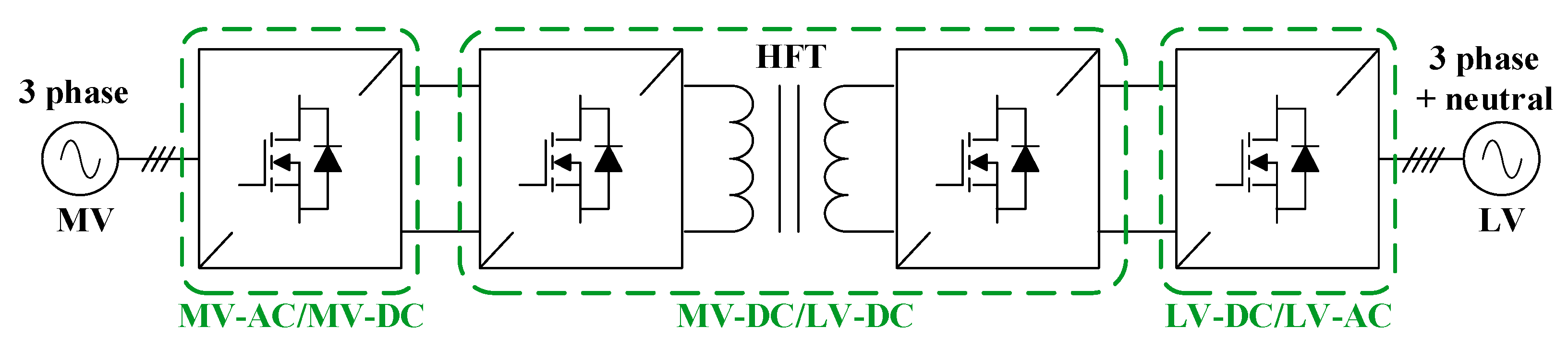
10]. Each of them enables different functionalities. However, the most promising in terms of scalability, maintenance, and fault tolerance seems to be the three-stage power conversion architecture, which contains a MV-AC to MV-DC conversion stage, a DC-MV to DC-LV conversion stage (with HFT for galvanic isolation, which is required by many grid codes), and an LV-DC to LV-AC conversion stage, as shown in
Figure 1.
This configuration introduces a new layer of functionality and assures additional freedom regarding its control scheme. The most prominent advantages are [
4,
5,
6,
9,
10]:
an intermediate DC stage allowing integration with DC grids (on both MV and LV sides) without additional AC/DC conversion stages;
precise control of power flow with high dynamics and four-quadrant operation (active and reactive power in either direction), resulting in low transmission losses;
ability to independently compensate both reactive power and current higher harmonics on either side of the SST;
very high volumetric power density (kW/dm3), resulting in reduced use of materials;
per-phase current control with possibility for the stand-alone mode of operation;
ride-through operation under various voltage disturbances with the inherent decoupling feature between two sides due to DC stage;
post-fault operation in case of internal or grid-related failure;
fast dynamic response and/or reconfiguration in response to events in the distribution system due to operator-level communication layer;
LV-side voltage control with the ability to compensate non-linear loads.
In the case of three-conversion-stage SST, the LV and the MV stages can be treated separately. This paper focused on the MV-AC to the MV-DC stage. Considering the MV side, the SST’s most important functionalities are:
ability to isolate disturbances between both sides;
precise current/power control, especially in case of voltage imbalances or other distortions;
adjustable power factor;
post-fault operation capability;
ability to compensate higher harmonics of current.
The paper presents a simple control solution for MV-AC to MV-DC stages based on a cascaded H-bridge (CHB) converter enabling different current control strategies to distribute power among the phases in an MV grid in case of voltage imbalances depending on what is needed from the MV grid perspective such as constant MV grid active power, symmetrical line currents, or the faulted phase being unloaded. Although there are methods to control the star-connected CHB converter presented in the literature [
11,
12,
13,
14,
15], such current control strategies with additional input parallel output parallel dual active bridge converters (IPOP DAB) reference current calculations were not reported. In such scenarios, the IPOP DAB (interfacing MV-AC to MV-DC and LV-DC to LV-AC conversion stages) works as an active load with non-equal current distribution for the SMs of the star-connected CHB converter. This paper is organized as follows. In
Section 2, the main topologies of MV-AC to MV-DC converters suitable for SST are briefly described with the justification of the choice of a CBH converter. In
Section 3, a control algorithm used for MV-AC to MV-DC stage is explained.
Section 4 describes three control modes that can be applied during line voltage imbalances in the MV grid. Then,
Section 5 and
Section 6 show simulation and experimental results. Eventually,
Section 7 contains conclusions.
2. Converter Topologies for the MV-AC to MV-DC Stage of the SST
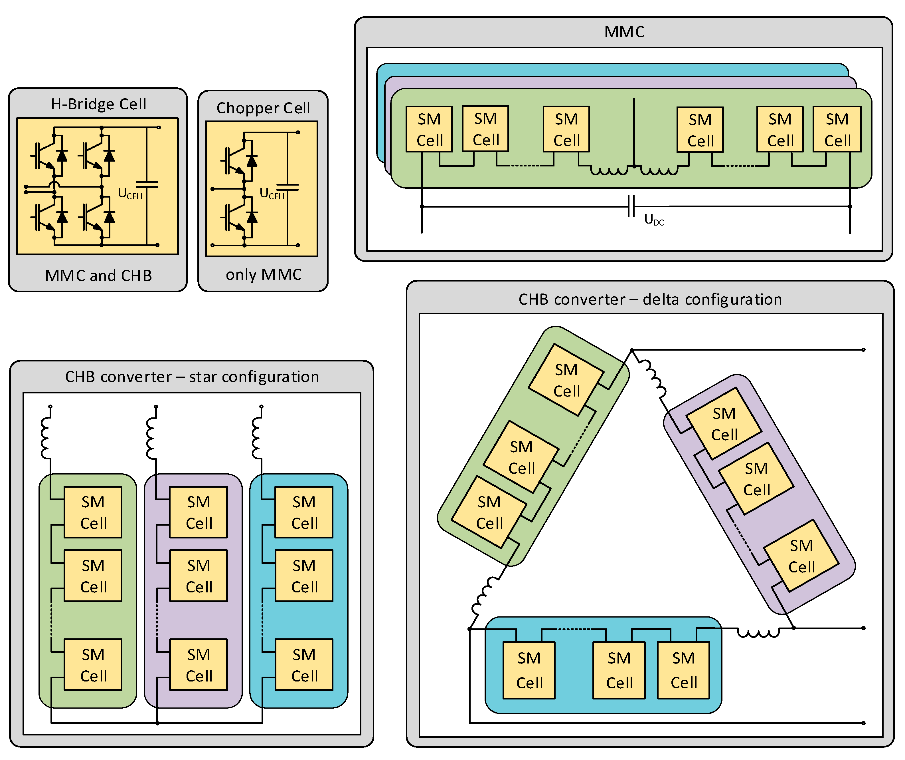
A converter that connects SST with MV grid should be realized using multilevel topology. A high number of voltage levels brings many advantages to the system, such as post-fault operation ability, the possibility to reduce passive elements, lower voltage stress on single power electronics elements, lower switching frequency, and lower total harmonics current distortion [
16,
17]. Although many multilevel topologies exist, two based on the series connection of power electronics submodules (SMs) (half-H-bridges or full-H-bridges) [
18], namely modular multilevel converters (MMC) and cascaded H-bridge (CHB) converters [
19,
20], are well-suited for SST’s MV-AC to MV-DC (
Figure 2). Both topologies offer low losses and scalability; the number of voltage levels can be easily extended by adding more SMs.
The main topological difference is that MMC does have a common MV-DC link, while CHB does not. The lack of this link is also the main disadvantage of the CHB converter in SST application over the MMC, as it allows for MV-DC applications such as electric vehicle (EV) charging stations. Thus, MMC outperforms its alternatives at high voltages utilization.
Two CHB converter configurations are possible: star or delta. The star configuration is cheaper because of the lower number of SM cells for the same DC-link MV and semiconductors voltage class values while providing almost the same efficiency at light and heavy loads as MMC [
20]. The sizeable capacitive energy storage of the MMC also affects the cost of these units significantly. On the other hand, the delta configuration performs better at the distorted grid [
11]. Unfortunately, for both CHB configurations under unbalanced loads or grid disturbances, the issue of energy balancing arises both in-phase and interphase. If the DC voltages are not equal, the system may become unstable or even collapse. To solve the interphase balancing issue in the star configuration and to balance the energy between the converter’s arms, a zero-sequence voltage can be injected into each phase, while, in the delta configuration, the same function is performed by adding a zero-sequence current [
11]. However, the same problem arises for the MMC—voltage unbalance between SM voltages can lead to the DC current injection into the grid [
21].
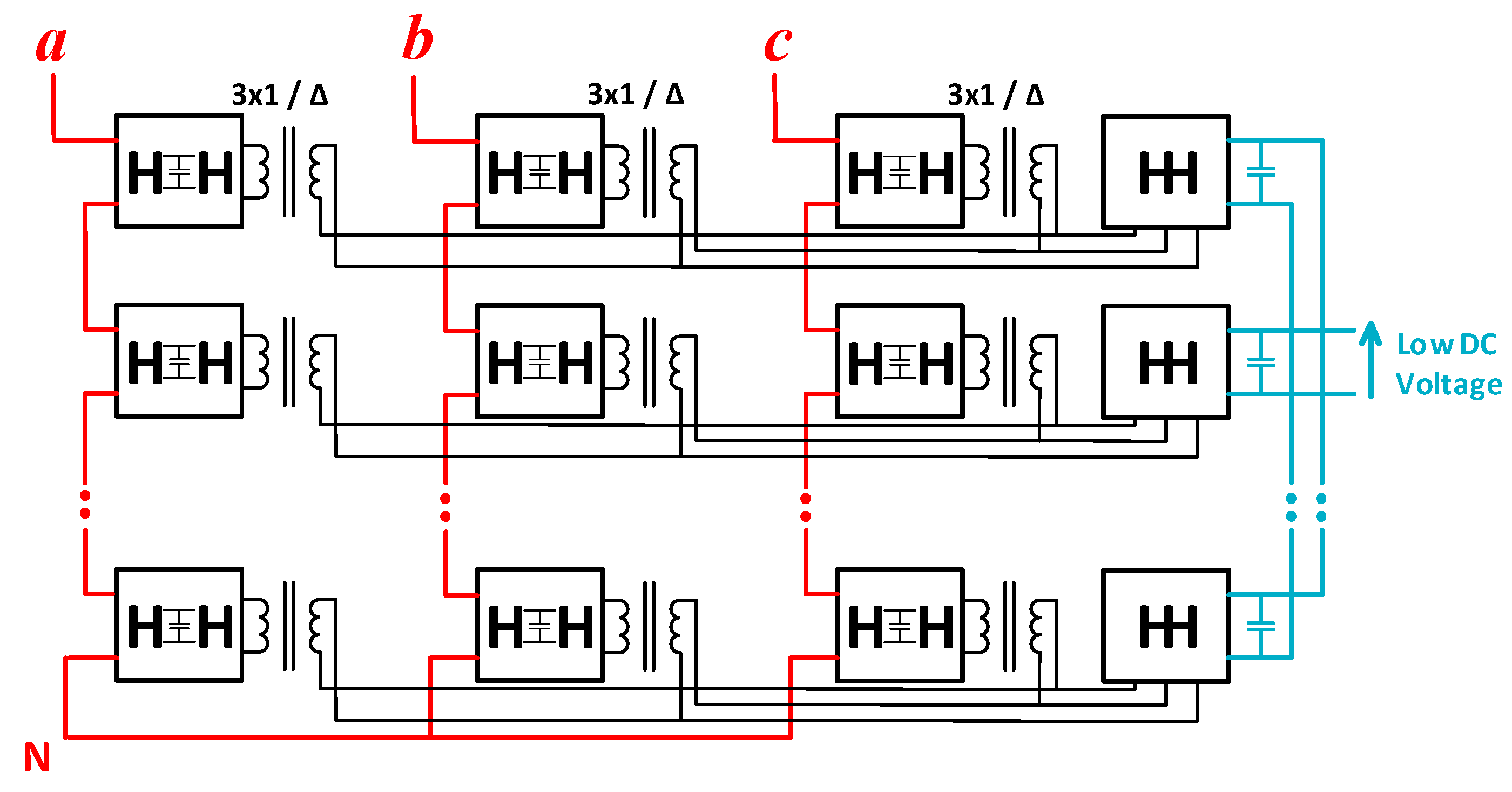
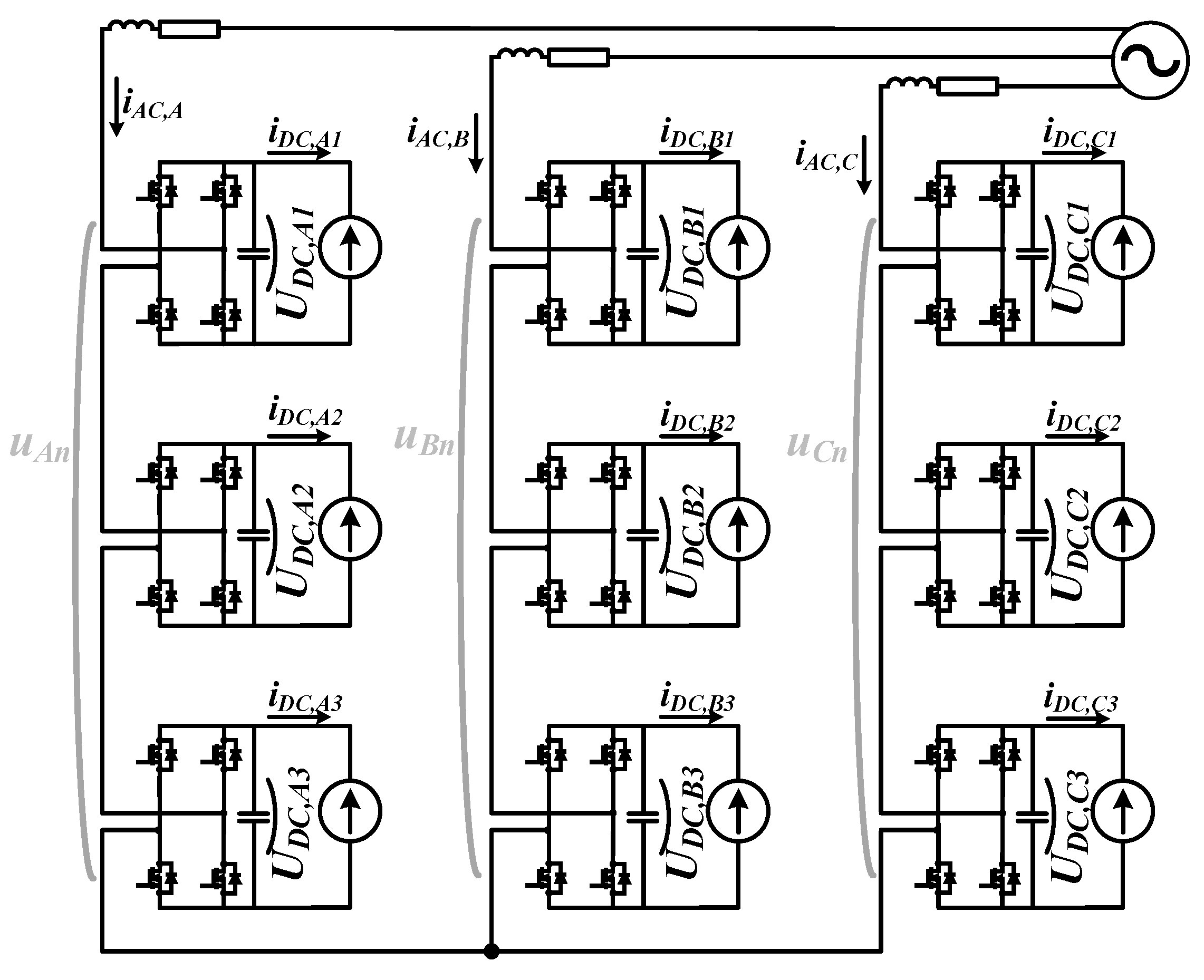
Taking into account that the post-fault operation ability is one of the most important SST functionalities from the MV grid side point of view, despite slightly lower efficiency and the lack of a common MV-DC link, the star-connected CHB converter was chosen for further analysis. It has fewer SM cells than MMC and delta-connected CHB converters, which reduces the possibility of failure. Secondly, with a proper DC-MV to DC-LV converter topology, it can achieve a higher freedom degree of a post fault operation. Especially a three-phase topology of a dual active bridge (DAB) converter with input parallel output parallel (IPOP) connection to the SMs—as shown in
Figure 3—is most suitable [
22,
23]. If a failure in one SM cell occurs, or even if the whole DAB fails, the failed SM can be bypassed. Other cells in the star-connected CHB converter must increase the output voltage to compensate the lack of one SM cell. However, the SST can still operate, ensuring the supply of end-user. The quality of the output voltage slightly decreases due to a lower number of operating modules, but this disadvantage is negligible in further SST operation.
Although there are methods to control star-connected CHB converters presented in the literature [
11,
12,
13,
14,
15], current control strategies for distributing power among the phases in an MV grid in the case of voltage imbalances with additional IPOP DAB reference current calculations were not reported. There is a possibility to apply different line current or power control strategies depending on what is needed from the MV grid point of view, such as constant MV grid active power, symmetrical line currents, or the faulted phase being unloaded. In such scenarios, the IPOP DAB works as an active load with non-equal current distribution for the SMs of the star-connected CHB converter.
3. Control Algorithm of a Star Connected Cascaded H-Bridge Converter
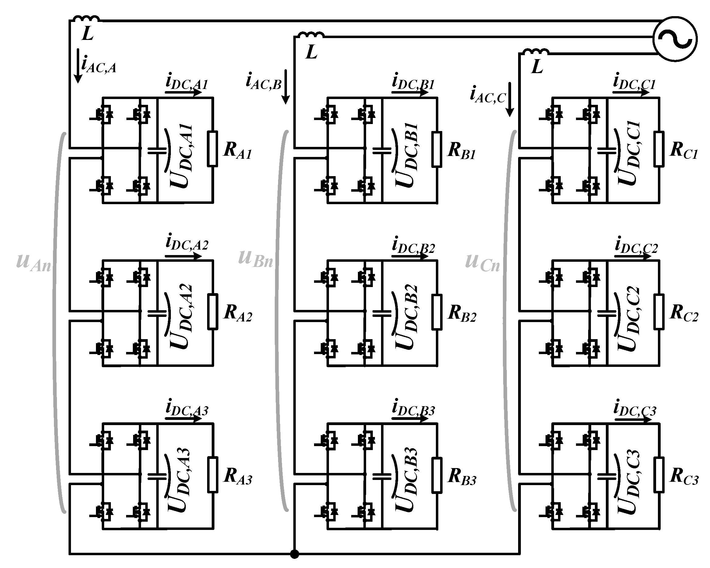
For clarity, this paper considered an MV-AC to an MV-DC stage of SST based on a star-connected CHB converter in which each leg consisted of three SMs, as shown in
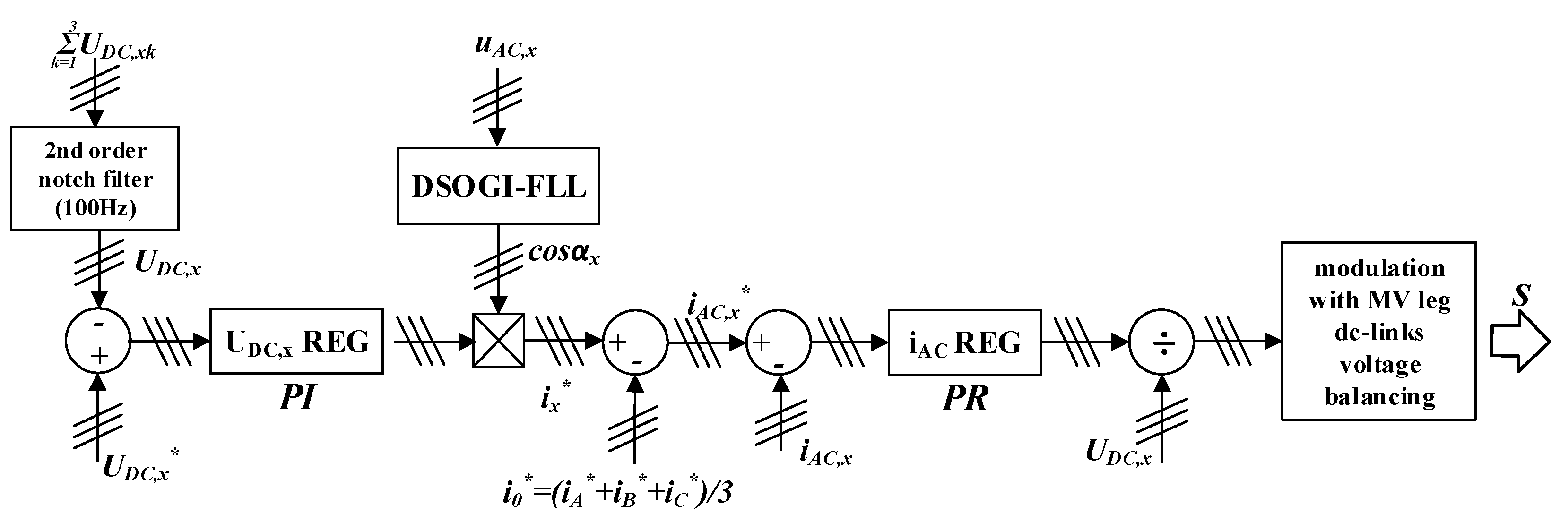
Figure 4. The proposed control algorithm for MV-AC to MV-DC stage contains two main control loops realized in the stationary frame. Its structure is shown in
Figure 5.
In each converter leg independently, an outer loop regulates the whole converter leg DC-link voltage
, where
x denotes the CHB converter’s leg. Measured SM DC-link voltages,
, where
k denotes the number of a SM cell, are filtered by a second-order notch filter to remove the second harmonic signal. These are then summed to obtain the whole converter leg DC-link voltage:
which is then subtracted from reference leg DC voltage
to obtain controller input error. The controller is proportional-integral (PI) type.
In each leg the inner line current
control loop is based on a proportional resonant (PR) controller that is able to eliminate not only steady-state amplitude but also phase error. To obtain a sinusoidal reference signal for the PR controller, the voltage controller output signal is multiplied by a cosinusoidal signal that is in phase with the line AC voltage. Synchronization with the grid is fulfilled by the frequency-locked loop based on a double second-order generalized integrator (DSOGI-FLL) [
24].
Separate converter leg DC voltages
control may cause a situation where the whole system regulation, in the case of load or MV grid imbalance or due to semiconductor elements nonlinearities, produces a zero sequence reference current, which, in the case of a three-wired system, can result in instability. In such a system, phase currents are coupled, and their sum is always zero:
That is why each leg current cannot be controlled separately [
11]. Phase decoupling is accomplished by calculating a zero sequence reference current
, where
are phase reference currents
set by DC voltage
control loop:
and subtracting it from phase reference currents
to obtain current PR controllers reference signals
:
Further, current PR controller input error signal is calculated by subtracting measured line AC currents from reference signals . Each current output regulator signal is divided by the converter corresponding leg DC-link voltage
DC-link voltage balancing between the H-bridges in one leg is realized by an algorithm implemented in the modulation scheme. It is based on checking, in each switching period, which capacitors in a leg should be charged or discharged (depending on the current flow direction) to maintain all DC voltages at the same level.
MV-AC to MV-DC Stage Dynamics Improvement
In order to improve the system dynamics, an active (based on the control signals) power feedforward (PFF) from LV side to MV side is implemented. It is based on the assumption that when neglecting losses, active power needed to be transferred from or to an MV-AC grid can be equated to LV DC-link power. The amount of active power needed for MV-AC/MV-DC converter
can be calculated as:
In the case of a star-connected CHB, it is possible to distribute the power unevenly between the phases, which is especially useful during faults and imbalances. That means that also PFF can be calculated separately for each MV converter leg. Single-phase active power taken from the grid, assuming that currents and voltages are sinusoidal and in-phase (power factor is equal one), can be calculated based on amplitudes of the MV grid line current and voltage:
However, in the proposed CHB control algorithm, the controlled signals are DC voltages and AC currents rather than powers.Thus the most convenient way to implement PFF to the control structure is to apply it in the form of a current signal. The easiest solution is to add it to the output DC voltage
controller signal before multiplying it by synchronized with the MV grid sinusoidal signal. Thus, the final equation to calculate leg PFF current can be written as:
where
depends on control mode. and its calculation is described in
Section 4. The whole control structure with PFF is shown in
Figure 6.
4. Power Distribution Strategies among the Phases in MV Grid
When MV grid line voltages are symmetrical, desired grid currents are symmetrical as well. However, in case of any MV line voltage imbalance, there is a possibility to apply some different line current or power control strategies depending on what is needed from the MV grid point of view. During any fault, the operator may need to obtain constant MV grid active power, symmetrical line currents, or have the faulted phase unloaded. The SST with proper control can provide these functionalities in opposition to conventional distribution transformers.
There are some known strategies to control the converter currents and powers during grid faults, such as separate control loops for currents in
dq reference frame (in both positive and negative sequences) or model-based predictive control [
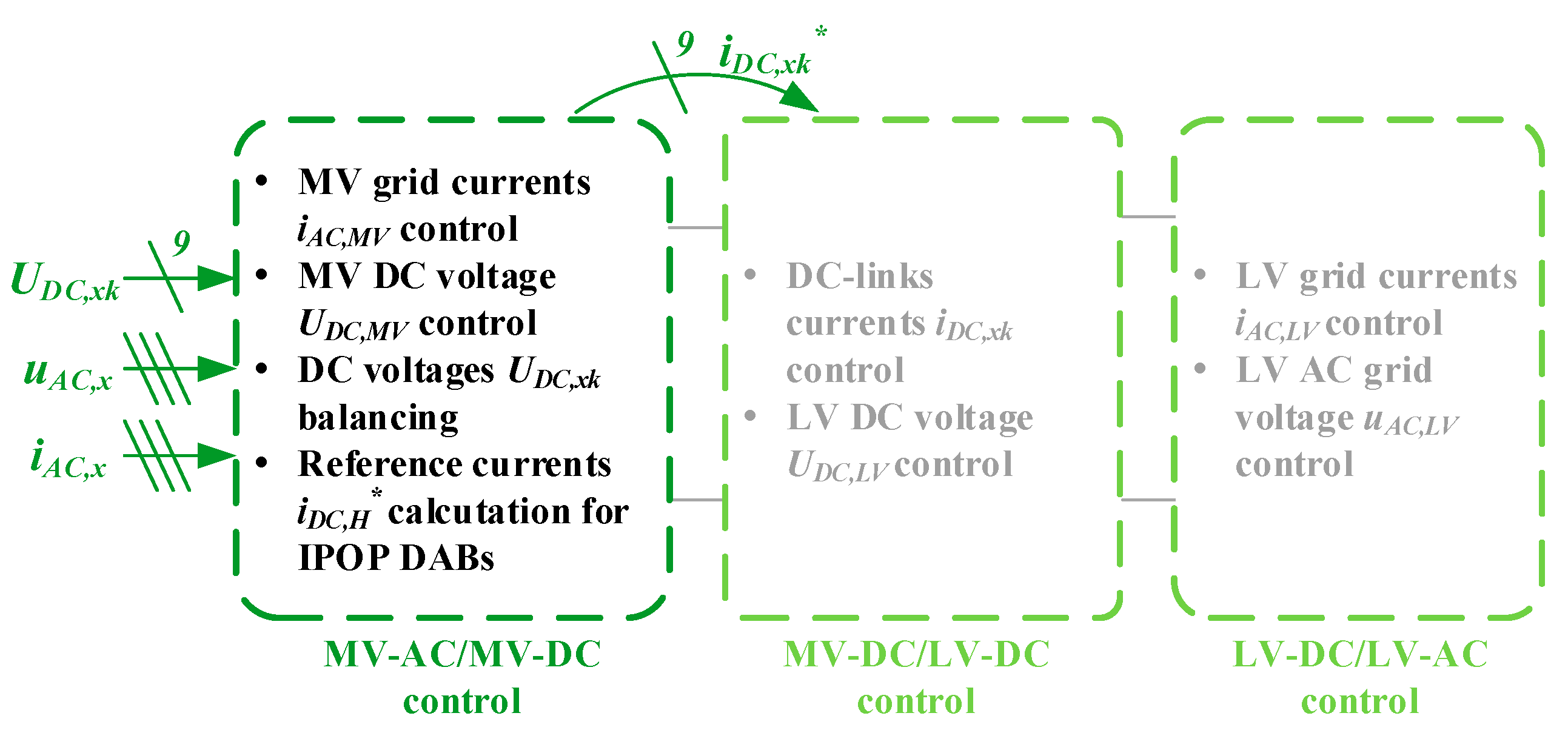
24]. However, most of them are quite complicated in use. In application to star-connected CHB converter-based SSTs, there exists an alternative approach, which retains the control of MV-AC to MV-DC stages without any modifications. Instead, the proposed technique is based on the reference currents for MV-DC to LV-DC IPOP DAB converters non-equal distribution depending on the chosen control mode. That operation does not change the total SST power but changes its flow inside the transformer, exactly between single star-connected CHB and MV-DC to LV-DC IPOP DAB H-bridges. The block scheme with functions of each stage of the SST’s control, emphasizing the MV-AC/MV-DC part, is shown in respect to the considered MV-AC to MV-DC stage of the SST in
Figure 7. To simplify the theoretical analysis, line voltage distortions (such as higher harmonics) as well as the voltage distortions at the converter’s output (caused by dead times and semiconductors’ voltage drops) are omitted, as they affect both AC and DC power calculations.
4.1. Constant Active Power
In a constant MV grid active power mode, the same amount of active power should be taken from each phase; thus, in case of a voltage sag in any phase, its current amplitude can rise to maintain constant power. The control algorithm is able to provide sinusoidal grid currents
, but with different amplitudes in each phase. In this mode, only low voltage side
DC power is needed for calculations of reference power for each H-bridge, because
DC power is divided equally between the MV grid phases. Reference phase active power calculation is realized by:
In the proposed system, currents are controlled directly rather than powers, thus following the Equation (5) reference for the current to be transferred from or to each CHB H-bridge (depending on the power flow direction) can be calculated easily as:
In each of the three proposed control modes, reference phase power is calculated in a different way, but reference DC current for every H-bridge is computed identically.
4.2. Symmetrical Grid Currents
In symmetrical currents mode, reference power calculation is based on the fact that in each phase the current amplitude should be the same. Thus AC power can be calculated as a three-phase power to obtain current amplitude. Then, using grid voltage direct component computed as in PFF, each phase reference power can be calculated.
Grid currents amplitude which will be equal in each phase as well as three-phase power are calculated as:
However, it is necessary to use positive components of voltages in
αβ reference frame
rather than
, to obtain balanced sinusoidal currents in the grid.
Next, the reference phase active power is calculated:
and then reference DC current for every H-bridge
is computed as in Equation (9).
4.3. Constant Reactive Power Mode—Phase Unloading
Unloading the phase in which a voltage sag occurs can be called constant reactive power mode or phase unloading mode. It would be useful when there exist strict requirements for managing reactive power during voltage sags in the grid. This strategy provides MV grid constant reactive power while keeping line currents sinusoidal. Reference phase active power calculation is based on the squared grid voltage direct components
to distribute the power in a way to unload the phase in which there is a voltage sag:
and then reference DC current for every H-bridge
is calculated as in Equation (9).
In some cases, it might be possible or necessary to totally unload the faulted phase. In such an occurrence, unloading could be realized by dividing the needed active power equally by the two remaining phases. However, it does not seem to be useful in practical situations, and it was not investigated in this paper.
5. Simulation Results
A simulation model to prove the performance of the proposed control was created in PLECS software with the algorithm written in C language. Each leg of an MV-AC to an MV-DC stage of an SST based on a star-connected CHB converter in respect to
Figure 4 consists of three SM. DC-MV to DC-LV converters were replaced (according to Equation (9) in respect to the chosen power distribution strategy) by controlled current sources to simplify the simulation. The simulation model is shown in
Figure 8. Simulation parameters are collected in
Table 1. The semiconductor devices are modeled with ideal switches.
The behavior of the system is investigated in steady-state during nominal system conditions and while changing the direction of energy flow to also check if it is possible to transfer it in both directions—from MV grid and to MV grid. The second set of tests cover three proposed control modes during single-phase MV line voltage phase-to-ground voltage sag to 0.5 of nominal voltage.
Figure 9 shows simulation results for the steady-state of the system operating at nominal parameters with the energy flow from MV grid to LV grid. It can be seen that line currents are sinusoidal and in phase with line voltages. DC voltages in nine H-bridges are balanced, and their voltage fluctuation does not exceed 0.6% of the whole voltage. The MV grid active power is constant.
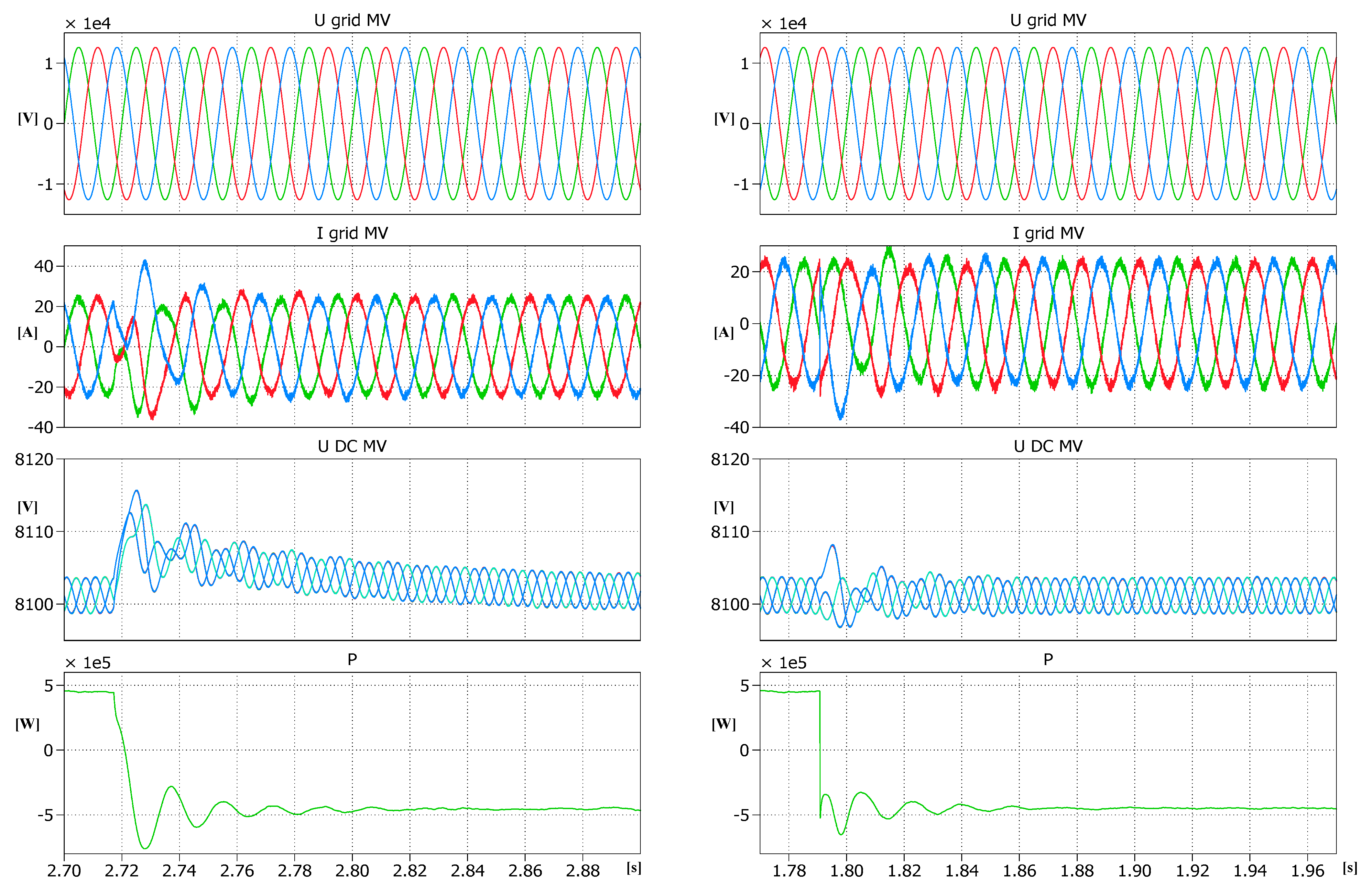
In
Figure 10, results for energy flow direction change are shown. Changes in active power change from nominal 450 kW transferred from MV-AC grid to DC currents sources to 450 kW in the opposite direction using the system without and with PFF are simulated. In both cases, grid currents are sinusoidal, and DC voltages are balanced. After implementing PFF (on the right), DC voltage transient is much shorter, and line currents peak transient values and grid active power oscillation are reduced.
In
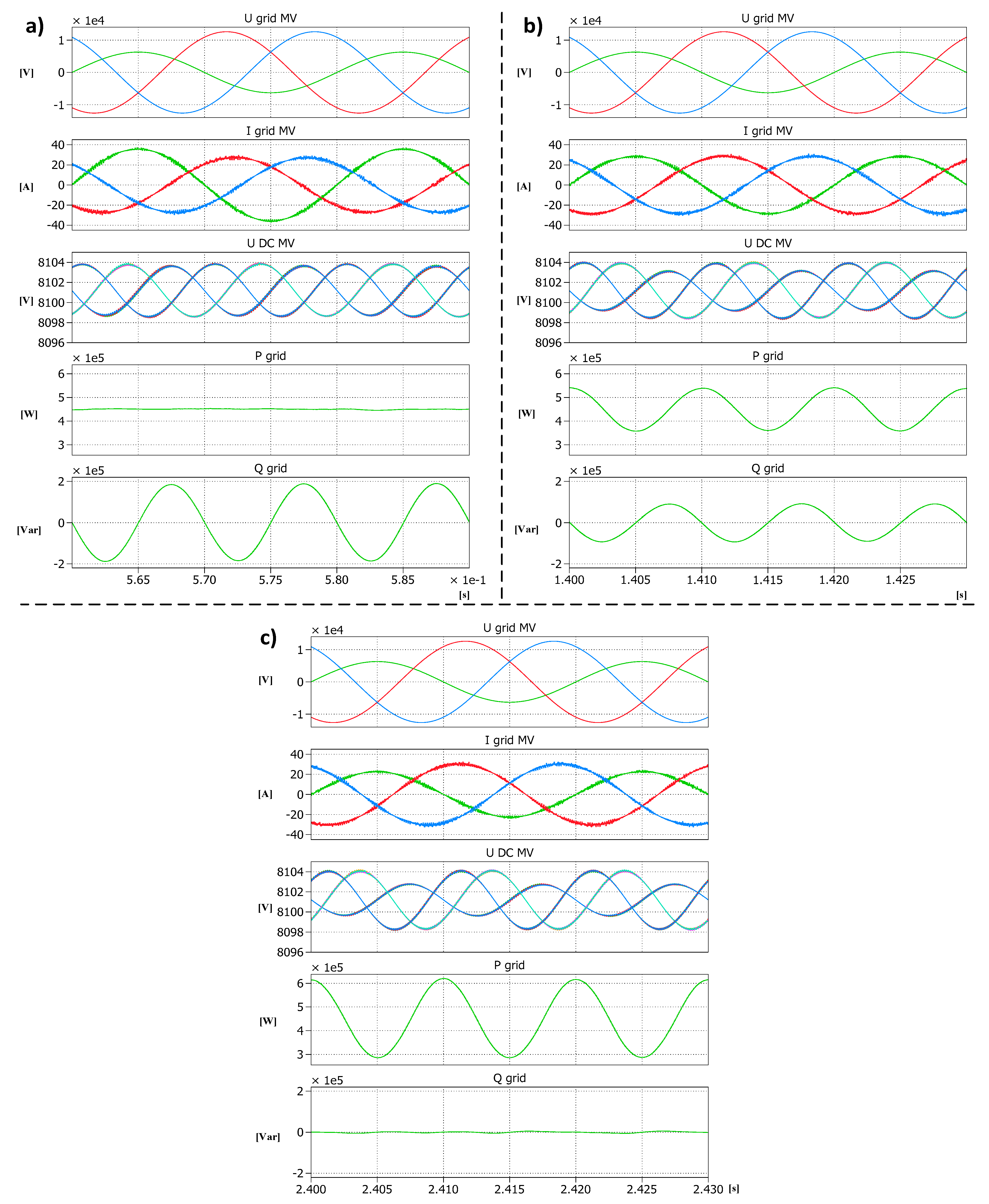
Figure 11, single phase-to-ground voltage sag to 0.5 nominal line voltage simulation results are shown in the case of three different proposed control modes. It can be seen that, in all three modes, grid currents are sinusoidal and nine DC-link voltages are balanced.
In constant active power mode, in
Figure 11a, amplitude of the faulted phase current is higher than in the other two and is in phase with the phase voltage, and because of the fact that
, the other two line currents are not in phase with the voltages, thus reactive power is not zero. The oscillations of DC voltages are in each phase the same, which confirms that, in all three converter legs, the power is equal, and in the grid the active power is constant. This situation would be suitable, for example, in cases when there are many constant power devices connected to the grid.
In symmetrical currents mode, in
Figure 11b, there are oscillations of grid active and reactive powers to maintain the symmetrical currents. DC voltage oscillations in the faulted leg are larger than in the other two legs. This mode would be useful in cases when there are many constant current devices connected to the grid.
In phase unloading mode, in
Figure 11c, it can be seen that grid reactive power is zero. DC voltage oscillations in a faulted leg are smaller than in the other two legs, which results from less power in the faulted leg. This situation would be suitable in cases when the grid operator needs to support the grid after a fault to fulfill the grid code.
6. Experimental Verification
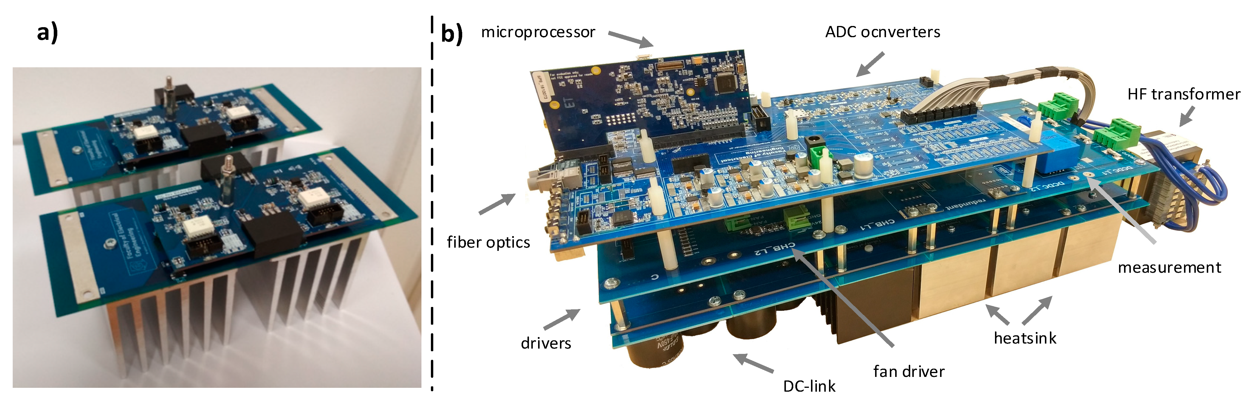
View of the designed single SM (consisting of two H-bridge modules, one for a CHB converter and the second for an IPOP DAB) of a AC-MV to a DC-LV converter is presented in
Figure 12b. The SM is based on a modular structure in which each leg is a separated power electronics building block, as shown in
Figure 12a. The power circuit is built on CREE C3M0065090J SiC transistors. In order to provide gate signals, ACPL-352J intelligent gate drive optocouplers are used. Each leg of the MV-AC to the MV-DC stage of SST based on a star-connected CHB converter in respect to
Figure 4 and
Figure 8 consist of three such a SMs. The simplified experimental model is shown in
Figure 13. Experimental setup parameters are shown in
Table 2.
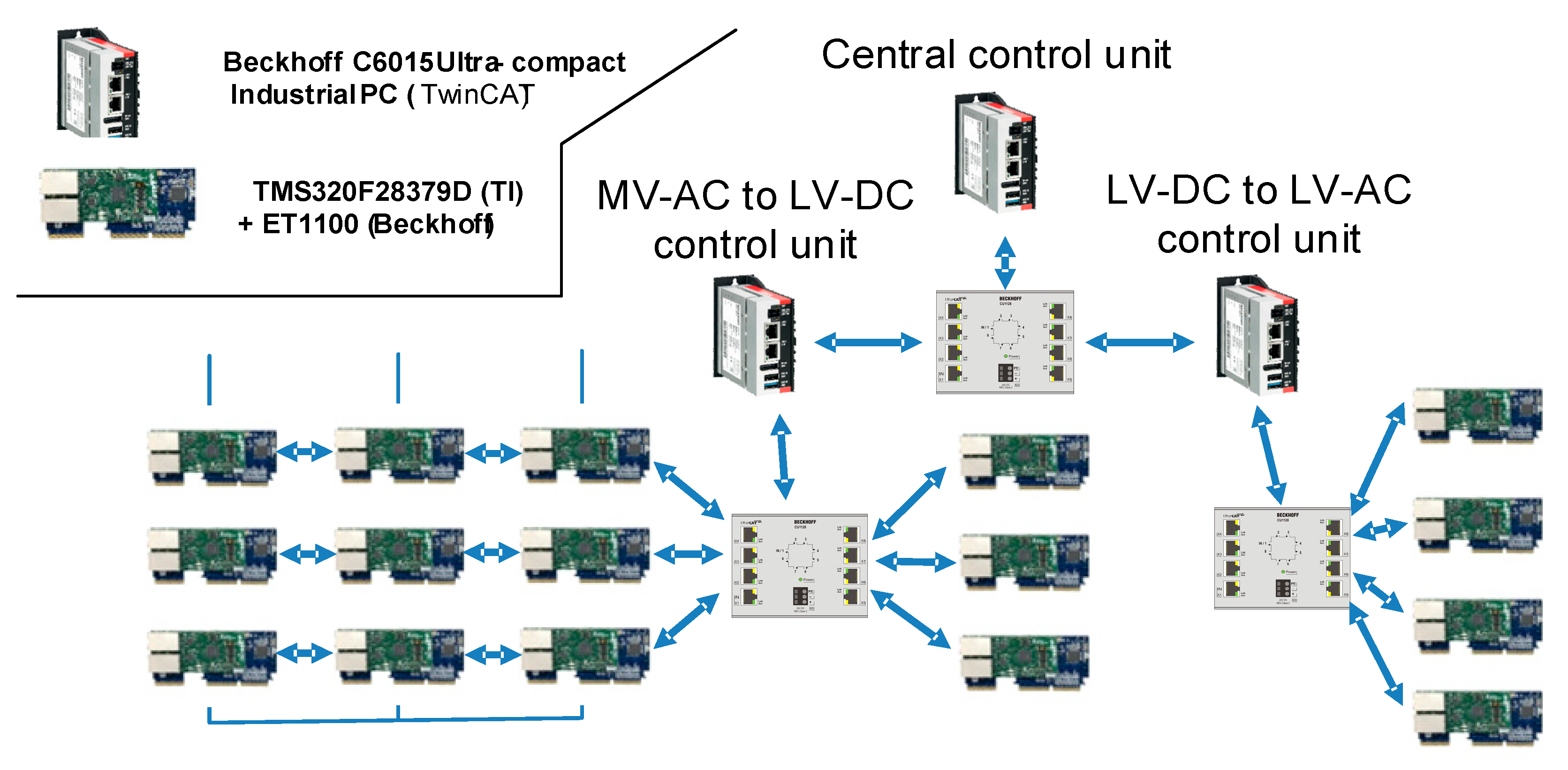
Taking into account that a star connected CHB converter consists of nine SMs, each using its own microprocessor to provide measurements and generate PWM signals, a distributed control system ensuring real-time communication among all SST blocks (including IPOP DAB LV side converters as well as DC-LV to AC-LV grid side converters) is needed. From available industrial distributed control systems, the EtherCAT was most suitable. The design of EtherCAT communication structure for the entire SST system is shown in
Figure 14, where the central control unit as well as MV-AC to LV-DC and LV-DC to LV-AC control units are the Beckhoff C6015 Industrial PCs. These computers are connected via ethernet with converters control units based on Texas Instruments TMS320F28379D microcontroller and Beckhoff ET1100 EtherCAT slave unit. One core of each TMS320F28379D microcontroller is responsible for communication via ET1100 EtherCAT slave unit with other TMS320F28379D microcontrollers and the Beckhoff C6015 control units, while the second core is responsible for measurements and PWM signals generation. For the purposes of this paper, only the MV-AC to the LV-DC control unit without IPOP DAB LV side converters was used. In this configuration, the control algorithm described in
Section 3 and
Section 4 was implemented in MV-AC to LV-DC Beckhoff C6015 control units. The Beckhoff C6015 control unit collects the measured values of currents and voltages of individual converters and, after performing the calculations, sends the set value of the PWM signal to each TMS320F28379D microcontroller. Taking into account that the switching frequency for a single H-Bridge was 100 kHz, the sampling frequency had to be lowered because of the limit for the communication period (when TwinCAT software was used) being 50 µs. In this case, the control sampling frequency was set to 10 kHz.
As the DC-link voltage balancing between the H-bridges in one leg was realized by an algorithm implemented in a modulation scheme in the Beckhoff C6015 control unit, and the DC-link voltage values between modules were refreshed every 10 switching periods, a modification of a PWM signal calculation was required to generate given output voltage. The DC voltages changed (depending on the current flow direction) between each switching period, and if the same duty cycle was applied in all 10 switching periods, the output voltage was generated with increasing error. To eliminate that in each TMS320F28379D microcontroller, the duty cycle was recalculated in relation to instantaneous voltages .
Figure 15 shows experimental results for steady-states of the system operating under symmetrical and unbalanced grid voltages (single phase-to-ground voltage sag to 0.5 nominal line voltage) as well as equal and non-equal SM loads (load for a one SM is two times smaller than for the others).
The proposed control algorithm is based on the assumption that it is possible to control the load currents of each submodule. In the simulation, the DC-MV to the DC-LV converters were substituted by controlled current sources to simplify the simulation. However, in experiment, it would be necessary to use either the power electronics converters in the IPOD DAB configuration or the aforementioned controlled current sources to unify the conditions between simulation and experiment. Taking into account that the operation of the proposed control algorithm was verified using a passive load, the phase unloading mode was not possible to present. Load parameters are shown in
Table 2. In case of symmetrical grid voltages as well as equal SM loads, the converter operates as it does in constant current mode. It can be seen that grid currents are sinusoidal and balanced with nine DC-link voltages. In the case of unbalanced grid voltages as well as non-equal SM loads, the converter operates as it does in constant active power mode; the amplitude of the faulted phase current is higher than in the other two and is in phase with the phase voltage. Despite the lack of unified conditions between simulation and experiment, the presented results prove the validity of the proposed control algorithm.
7. Conclusions
In this paper, a new method to distribute power among the phases in the MV grid in the case of voltage imbalances with additional IPOP DAB reference current calculations was proposed for use in a solid-state transformer. Suitable MV-AC to MV-DC converter topology (star-connected CHB) and its control algorithm were described. Their behavior was verified in simulation and experimental studies. The results showed that, during both balanced and unbalanced conditions in the MV grid, the proposed method is able to provide different control modes that can be useful while connecting the SST to the MV grid, such as constant active power, symmetrical line currents, and faulted phase unloading. Each of these modes can be useful for the grid operator depending on the chosen priorities. The constant active power mode would be suitable in cases when there are many constant power devices connected to the grid. The symmetrical currents mode would be useful in cases when there are many constant current devices connected to the grid. Finally, the phase unloading mode would be suitable in cases when the grid operator needs to support the grid after a fault to fulfill the grid code.
Furthermore, the method is under ongoing development, which can be split into three directions. First, in terms of scalability, the control algorithm can be improved in order to cover MV-AC to MV-DC stages consisting of an arbitrary number of SM per phase. Another extension of the method includes SM fault handling and post-fault operation. It requires anticipating and designing suitable scenarios as well as implementing a separate procedure for converter reconfiguration and derating. Finally, from the perspective of a grid operator, it is also important to take into account line voltage distortions (such as higher harmonics) as well as the converter’s output voltage distortions (caused by dead times and semiconductors’ voltage drops) that affect both AC and DC power calculations. Thus, a proper power calculation as well as reference DC current calculations for every H-Bridge must be incorporated into every power distribution scheme.
Author Contributions
Conceptualization, M.G. and S.S.; methodology, M.G. and S.S.; formal analysis, M.G. and S.S.; simulation validation, M.G., S.S., experimental validation, C.S. and S.S.; writing—original draft preparation, M.G. and S.S.; writing—review and editing, S.S. and R.K., supervision, S.S.; project administration, S.S.; funding acquisition, S.S. All authors have read and agreed to the published version of the manuscript.
Funding
This research was funded by the TEAMTECH/2016-1/5 Project carried out within the TEAM-TECH program of the Foundation for Polish Science cofinanced by the European Union under the European Regional Development Fund.
Conflicts of Interest
The authors declare no conflict of interest. The funders had no role in the design of the study; in the collection, analyses, or interpretation of data; in the writing of the manuscript, or in the decision to publish the results.
References
- Bhattacharya, S. Transforming the Transformer. IEEE Spectr. 2017, 54, 38–43. [Google Scholar] [CrossRef]
- Tan, D.; Novosel, D. Energy Challenge, Power Electronics and Systems (Peas) Technology and Grid Modernization. CPSS Trans. Power Electron. Appl. 2017, 2, 3–11. [Google Scholar] [CrossRef]
- Wang, J.; Huang, A.Q.; Sung, W.; Liu, Y.; Baliga, B.J. Smart Grid Technologies. IEEE Ind. Electron. Mag. 2009, 3, 16–23. [Google Scholar] [CrossRef]
- Huang, A.Q.; Crow, M.L.; Heydt, G.T.; Zheng, J.P.; Dale, S.J. The Future Renewable Electric Energy Delivery and Management (FREEDM) System: The Energy Internet. Proc. IEEE 2011, 99, 133–148. [Google Scholar] [CrossRef]
- Liserre, M.; Buticchi, G.; Andresen, M.; De Carne, G.; Costa, L.; Zou, Z.-X. The Smart Transformer: Impact on the Electric Grid and Technology Challenges. IEEE Ind. Electron. Mag. 2016, 10, 46–58. [Google Scholar] [CrossRef] [Green Version]
- Huber, J.E.; Kolar, J.W. Applicability of Solid-State Transformers in Today’s and Future Distribution Grids. IEEE Trans. Smart Grid 2019, 10, 317–326. [Google Scholar] [CrossRef]
- McMurray, W. The Thyristor Electronic Transformer: A Power Converter Using a High-Frequency Link. IEEE Trans. Ind. Gen. Appl. 1971, IGA-7, 451–457. [Google Scholar] [CrossRef]
- McMurray, W. Power Converter Circuits Having a High Frequency Link. U.S. Patent US3517300A, 23 June 1970. [Google Scholar]
- Ruiz, F.; Peérez, M.A.; Espinoza, J.R.; Gajowik, T.; Stynski, S.; Malinowski, M. Surveying Solid-State Transformer Structures and Controls: Providing Highly Efficient and Controllable Power Flow in Distribution Grids. IEEE Ind. Electron. Mag. 2020, 14, 56–70. [Google Scholar] [CrossRef]
- Hannan, M.A.; Ker, P.J.; Lipu, M.S.H.; Choi, Z.H.; Rahman, M.S.A.; Muttaqi, K.M.; Blaabjerg, F. State of the Art of Solid-State Transformers: Advanced Topologies, Implementation Issues, Recent Progress and Improvements. IEEE Access 2020, 8, 19113–19132. [Google Scholar] [CrossRef]
- Sochor, P.; Akagi, H. Theoretical Comparison in Energy-Balancing Capability between Star- and Delta-Configured Modular Multilevel Cascade Inverters for Utility-Scale Photovoltaic Systems. IEEE Trans. Power Electron. 2016, 31, 1980–1992. [Google Scholar] [CrossRef]
- Tafti, H.D.; Maswood, A.I.; Konstantinou, G.; Townsend, C.D.; Acuna, P.; Pou, J. Flexible Control of Photovoltaic Grid-Connected Cascaded H-Bridge Converters During Unbalanced Voltage Sags. IEEE Trans. Ind. Electron. 2018, 65, 6229–6238. [Google Scholar] [CrossRef]
- Li, X.; Geng, H.; Yang, G.; Li, R.; Zhang, C. Comparison of Different DC-Link Voltage Balancing Methods for Cascade H-Bridge Multilevel Converter. In Proceedings of the 17th International Conference on Electrical Machines and Systems (ICEMS), Hangzhou, China, 22–25 October 2014. [Google Scholar]
- Lee, C.; Wang, B.; Chen, S.; Chou, S.; Huang, J.; Cheng, P.; Akagi, H.; Barbosa, P. Average Power Balancing Control of a STATCOM Based on the Cascaded H-Bridge PWM Converter With Star Configuration. In Proceedings of the 2013 IEEE Energy Conversion Congress and Exposition, Denver, CO, USA, 15–19 September 2013. [Google Scholar]
- Raveendran, V.; Buticchi, G.; Liserre, M.; Mercante, A. Comparison of Voltage Control Methods of CHB Converters for Power Routing in Smart Transformer. In Proceedings of the 2017 IEEE Energy Conversion Congress and Exposition (ECCE), Cincinnati, OH, USA, 1–5 October 2017. [Google Scholar]
- Rodriguez, J.; Lai, J.S.; Peng, F.Z. Multilevel Inverters: A Survey of Topologies, Controls, and Applications. IEEE Trans. Ind. Electron. 2002, 49, 724–738. [Google Scholar] [CrossRef] [Green Version]
- Kouro, S.; Malinowski, M.; Gopakumar, K.; Pou, J.; Franquelo, L.G.; Wu, B.; Rodriguez, J.; Pérez, M.A.; Leon, J.I. Recent Advances and Industrial Applications of Multilevel Converters. IEEE Trans. Ind. Electron. 2010, 57, 2553–2580. [Google Scholar] [CrossRef]
- Akagi, H. Classification, Terminology, and Application of the Modular Multilevel Cascade Converter (MMCC). IEEE Trans. Power Electron. 2011, 26, 3119–3130. [Google Scholar] [CrossRef]
- Briz, F.; Lopez, M.; Rodriguez, A.; Arias, M. Modular Power Electronic Transformers: Modular Multilevel Converter versus Cascaded H-Bridge Solutions. IEEE Ind. Electron. Mag. 2016, 10, 6–19. [Google Scholar] [CrossRef]
- Wang, G.; Konstantinou, G.; Townsend, C.D.; Pou, J.; Vazquez, S.; Demetriades, G.D.; Agelidis, V.G. A Review of Power Electronics for Grid Connection of Utility-Scale Battery Energy Storage Systems. IEEE Trans. Sustain. Energy 2016, 7, 1778–1790. [Google Scholar] [CrossRef] [Green Version]
- Vasiladiotis, M.; Cherix, N.; Rufer, A. Impact of Grid Asymmetries on the Operation and Capacitive Energy Storage Design of Modular Multilevel Converters. IEEE Trans. Ind. Electron. 2015, 62, 6697–6707. [Google Scholar] [CrossRef]
- Costa, L.F.; Hoffmann, F.; Buticchi, G.; Liserre, M. Comparative Analysis of Multiple Active Bridge Converters Configurations in Modular Smart Transformer. IEEE Trans. Ind. Electron. 2019, 66, 191–202. [Google Scholar] [CrossRef] [Green Version]
- Gajowik, T.; Sobol, C.; Stynski, S.; Malinowski, M. Post-Fault Operation of Hybrid DC-DC Converter for Solid-State Transformer. In Proceedings of the IECON 2017-43rd Annual Conference of the IEEE Industrial Electronics Society, Beijing, China, 29 October–1 November 2017. [Google Scholar]
- Teodorescu, R.; Liserre, M.; Rodriguez, P. Grid Converters for Photovoltaic and Wind Power Systems; Wiley: Chichester, West Sussex, UK, 2011. [Google Scholar]
Figure 1.
Block scheme of the SST consisting of three stages of power conversion with HFT.
Figure 1.
Block scheme of the SST consisting of three stages of power conversion with HFT.
Figure 2.
Modular multilevel converter and cascaded H-bridge converter topologies.
Figure 2.
Modular multilevel converter and cascaded H-bridge converter topologies.
Figure 3.
MV-AC to MV-DC stage of SST based on a star-connected CHB converter with IPOP DAB.
Figure 3.
MV-AC to MV-DC stage of SST based on a star-connected CHB converter with IPOP DAB.
Figure 4.
Considered MV-AC to MV-DC stage of SST based on a star-connected CHB converter.
Figure 4.
Considered MV-AC to MV-DC stage of SST based on a star-connected CHB converter.
Figure 5.
Scheme of chosen topology for ST’s MV-AC/MV-DC and MV-DC/LV-DC converters.
Figure 5.
Scheme of chosen topology for ST’s MV-AC/MV-DC and MV-DC/LV-DC converters.
Figure 6.
Scheme of chosen topology for ST’s MV-AC/MV-DC and MV-DC/LV-DC converters.
Figure 6.
Scheme of chosen topology for ST’s MV-AC/MV-DC and MV-DC/LV-DC converters.
Figure 7.
Main functions of each stage of SST’s control.
Figure 7.
Main functions of each stage of SST’s control.
Figure 8.
Simulation model.
Figure 8.
Simulation model.
Figure 9.
Steady-state operation at nominal power kW. From the top: grid line voltages , grid line currents , DC voltages , grid active power .
Figure 9.
Steady-state operation at nominal power kW. From the top: grid line voltages , grid line currents , DC voltages , grid active power .
Figure 10.
Change in the direction of energy flow:without PFF (on the left) and with PFF (on the right). From the top: grid line voltages , grid line currents , DC voltages , grid active power .
Figure 10.
Change in the direction of energy flow:without PFF (on the left) and with PFF (on the right). From the top: grid line voltages , grid line currents , DC voltages , grid active power .
Figure 11.
Steady-state operation during 50% phase-to-ground voltage sag: (a) constant active power mode of operation, (b) symmetrical currents mode of operation, (c) faulted phase unloading mode of operation. From the top: grid line voltages , grid line currents , DC voltages , grid active power , grid reactive power .
Figure 12.
Experimental setup: (a) view of designed power and driver boards of a single SM of a CHB converter, (b) view of designed single SM of a AC-MV to DC-MV converter with H-bridge of an IPOP DAB.
Figure 12.
Experimental setup: (a) view of designed power and driver boards of a single SM of a CHB converter, (b) view of designed single SM of a AC-MV to DC-MV converter with H-bridge of an IPOP DAB.
Figure 13.
Simplified experimental model.
Figure 13.
Simplified experimental model.
Figure 14.
Design of EtherCAT communication structure for whole smart transformer.
Figure 14.
Design of EtherCAT communication structure for whole smart transformer.
Figure 15.
Steady-state operation under: (a,b) symmetrical grid voltages, (c,d) unbalanced grid voltages, (a,c) equal SM loads, (b,d) non equal SM loads. From the top: grid line voltages , grid line currents , DC voltages .
Figure 15.
Steady-state operation under: (a,b) symmetrical grid voltages, (c,d) unbalanced grid voltages, (a,c) equal SM loads, (b,d) non equal SM loads. From the top: grid line voltages , grid line currents , DC voltages .
Table 1.
Simulation model parameters.
Table 1.
Simulation model parameters.
| Parameter | Value |
|---|
| Grid inductance | mH |
| Grid resistance | |
| Single H-bridge sampling frequency | |
| Carrier signal frequency | |
| System nominal active power | |
| Single H-bridge capacitance | |
| Single H-bridge nominal voltage | |
| Number of cells in phase | |
| Grid nominal voltage | line-to-line RMS |
Table 2.
Experimental setup parameters.
Table 2.
Experimental setup parameters.
| Converter Parameters |
| Parameter | Value |
| Grid inductance | mH |
| Control sampling frequency | kHz |
| Single H-bridge switching frequency | kHz |
| System nominal active power | kW |
| Single H-bridge capacitance | mF |
| Single H-bridge nominal voltage | V |
| Number of cells in phase | |
| Grid nominal voltage | Vline-to-line, RMS |
| Load Parameters |
| Parameter | Value |
| Equal load | Ω |
| Unequal load | Ω |
| Ω |
| Publisher’s Note: MDPI stays neutral with regard to jurisdictional claims in published maps and institutional affiliations. |
© 2021 by the authors. Licensee MDPI, Basel, Switzerland. This article is an open access article distributed under the terms and conditions of the Creative Commons Attribution (CC BY) license (https://creativecommons.org/licenses/by/4.0/).


