
Sensorless Control of Voltage Peaks in Class-E Single-Ended Resonant Inverter for Induction Heating Rice Cooker


Abstract
:1. Introduction
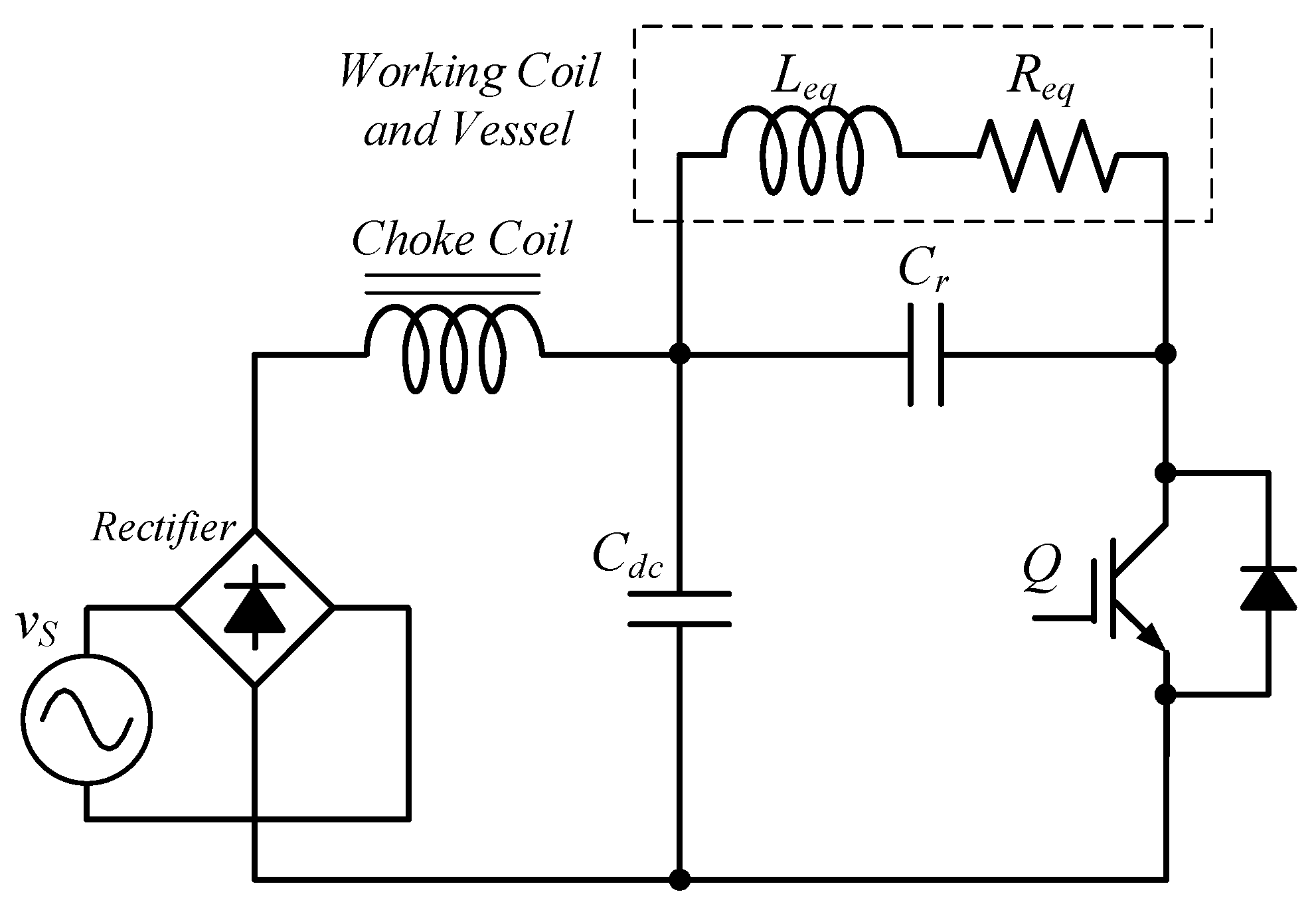
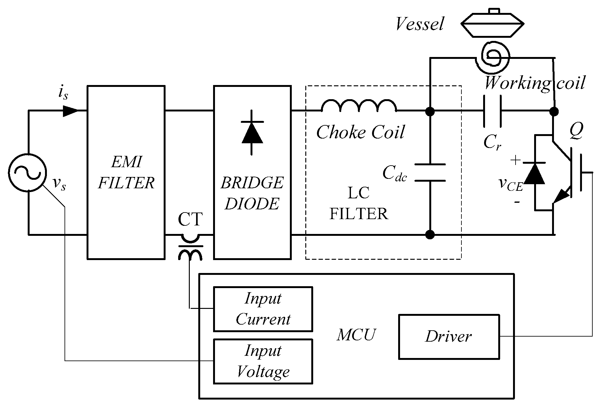
2. Methodology: Single-Ended (SE) Resonant Inverter for Induction Heating Rice Cooker
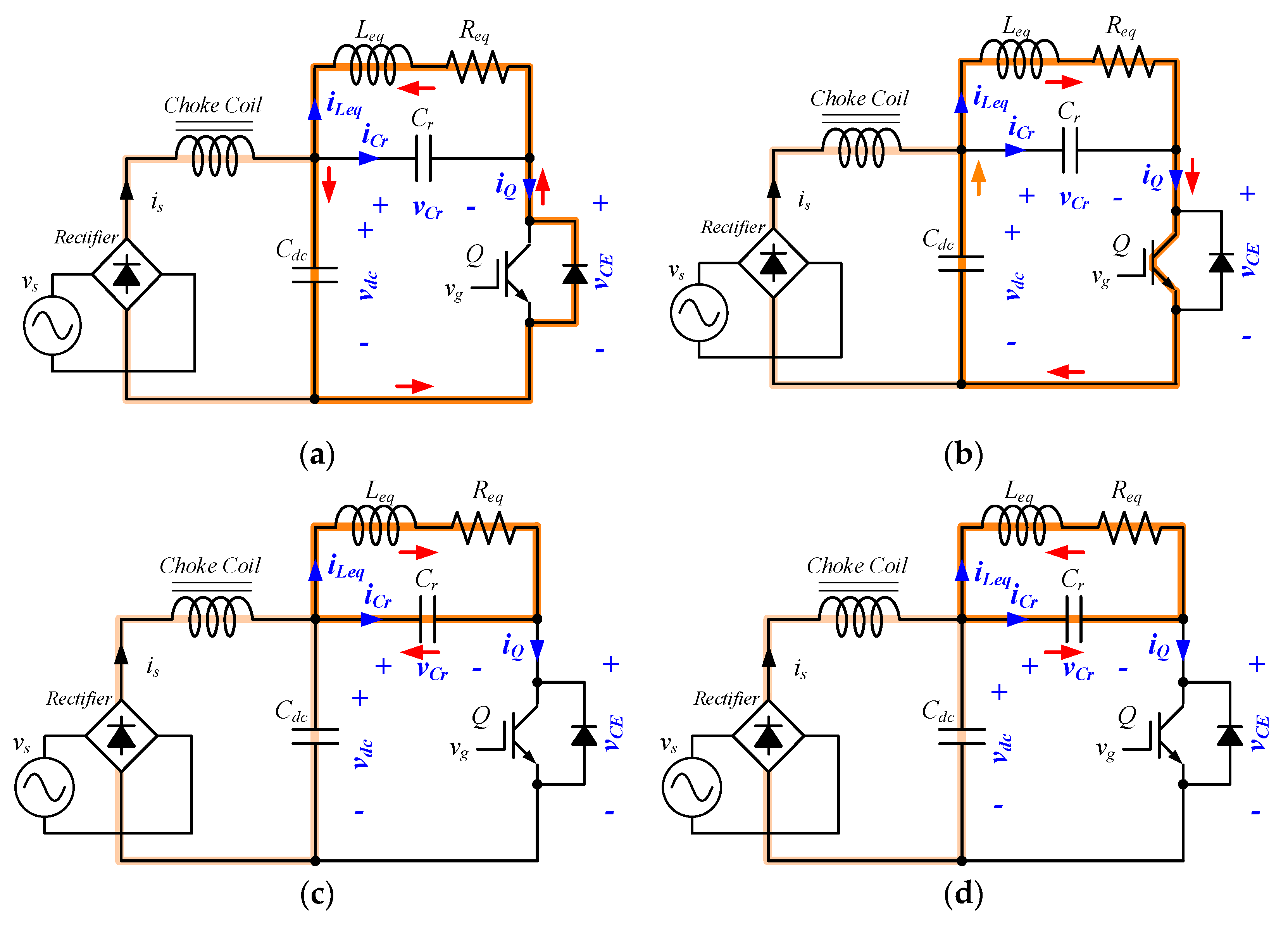
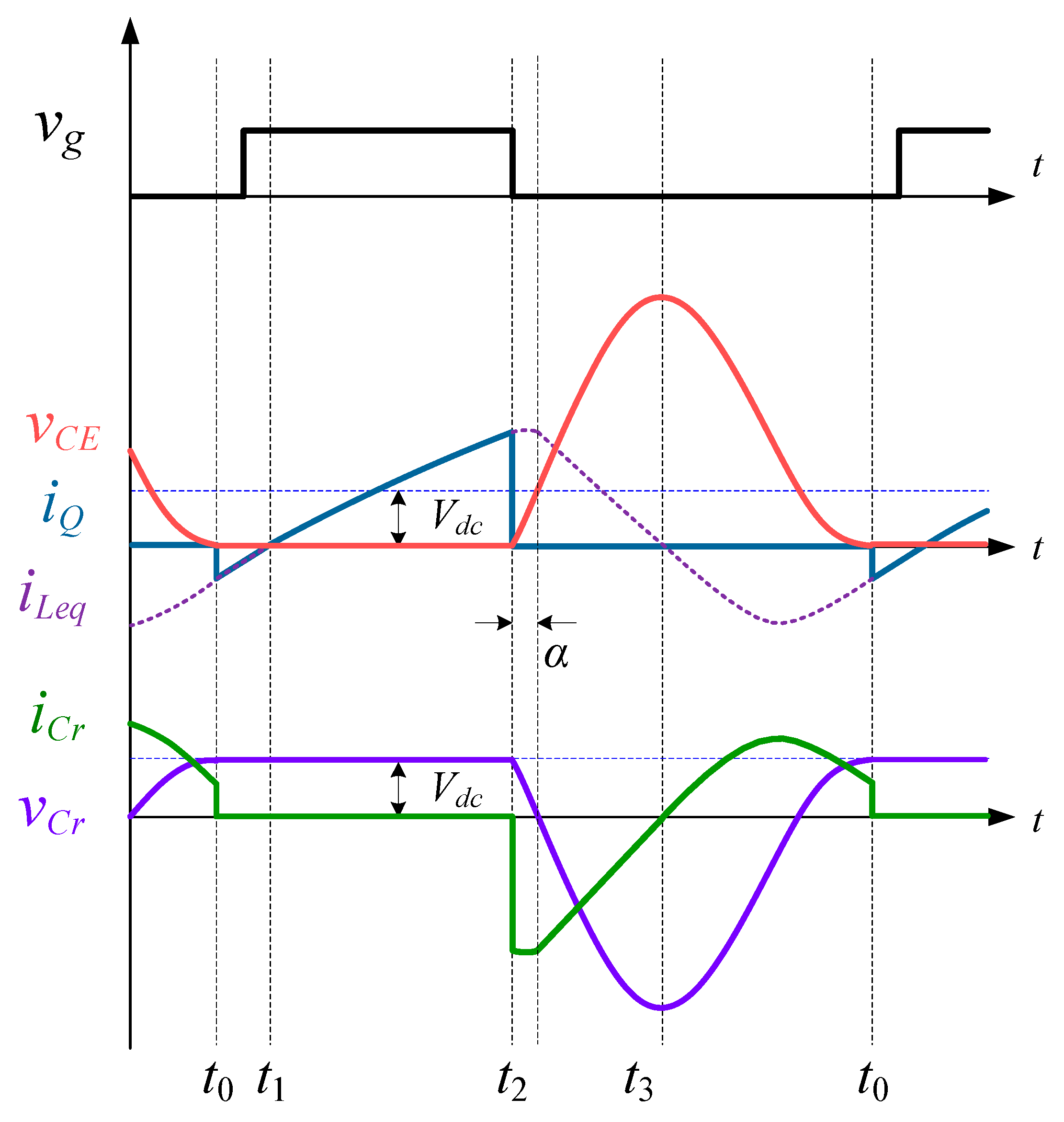
2.1. Operation Mode of the Equivalent Resonant Circuit
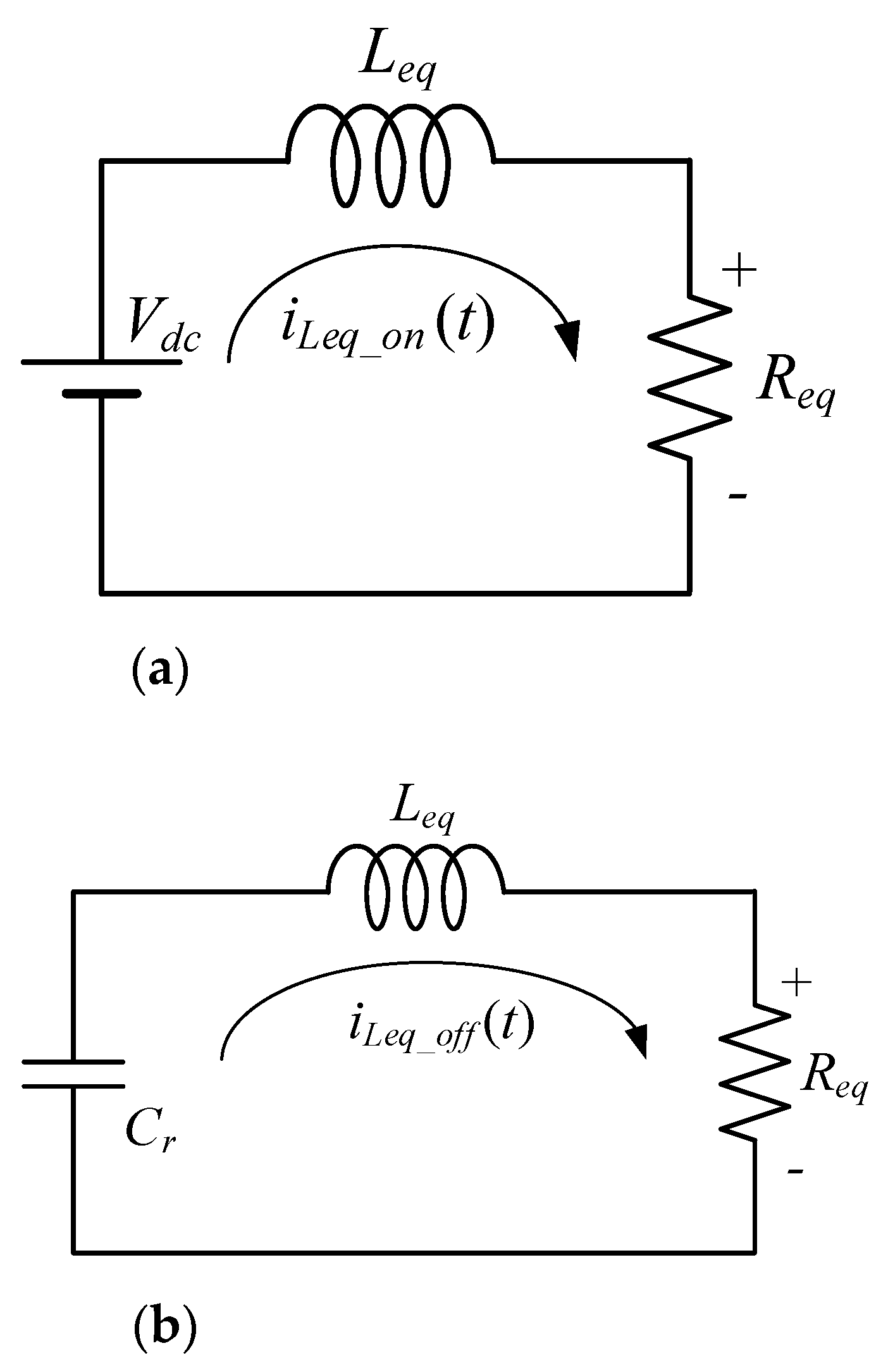
2.2. Anlalysis of the Equivalent Resonant Circuit
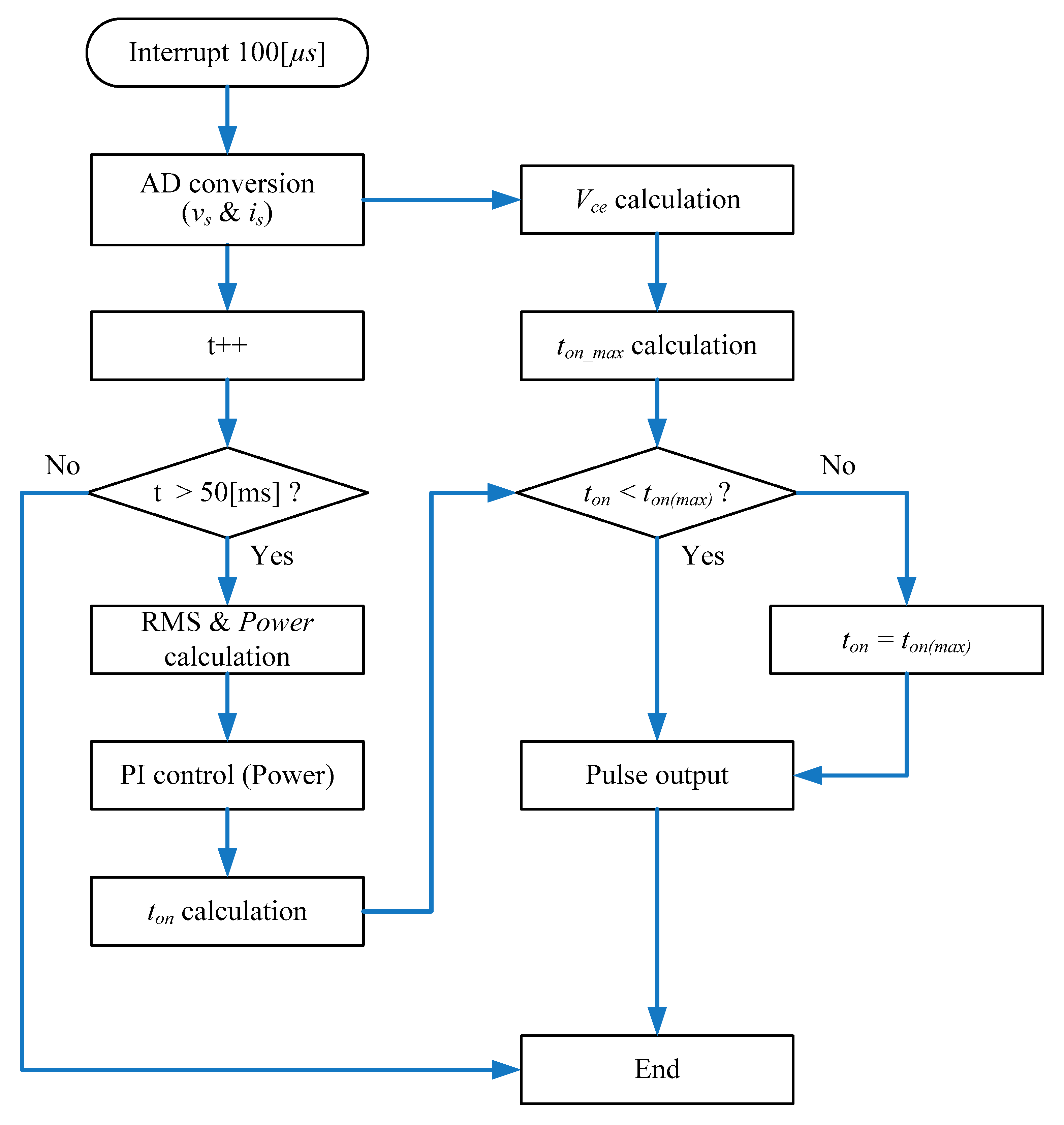
2.3. Sensorless Control of Voltage Peaks by Resonant Voltage Estimation Using the Turn-On Duration of the IGBT
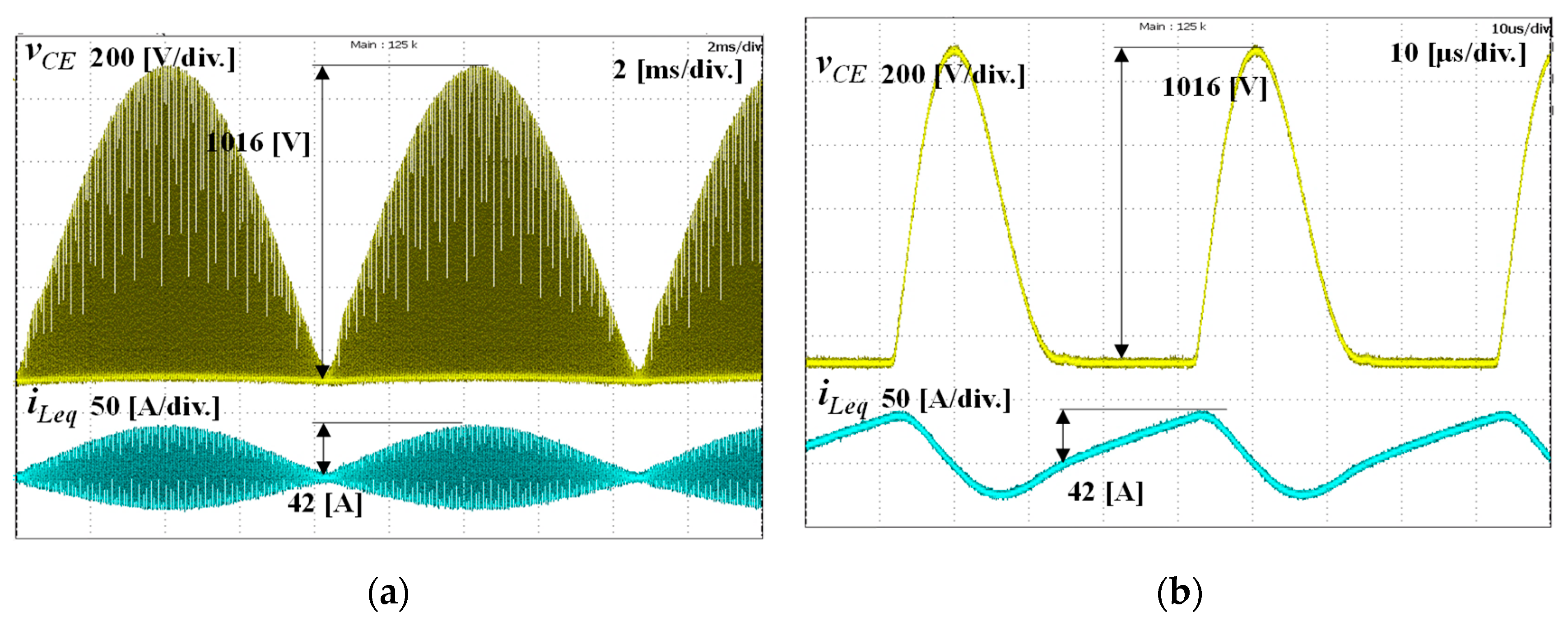
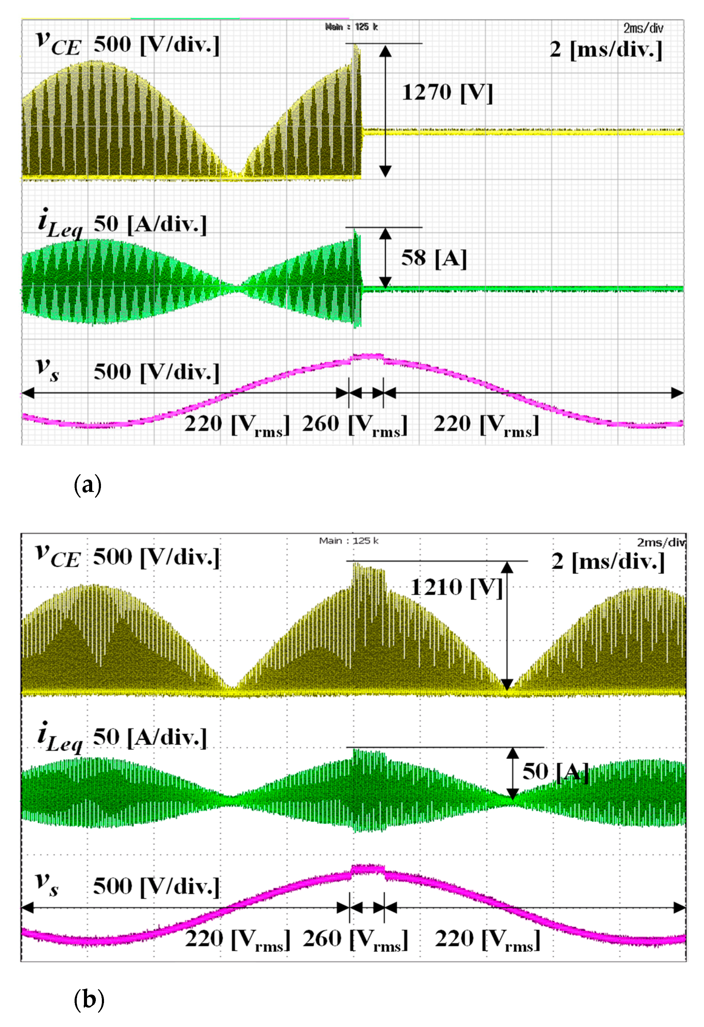
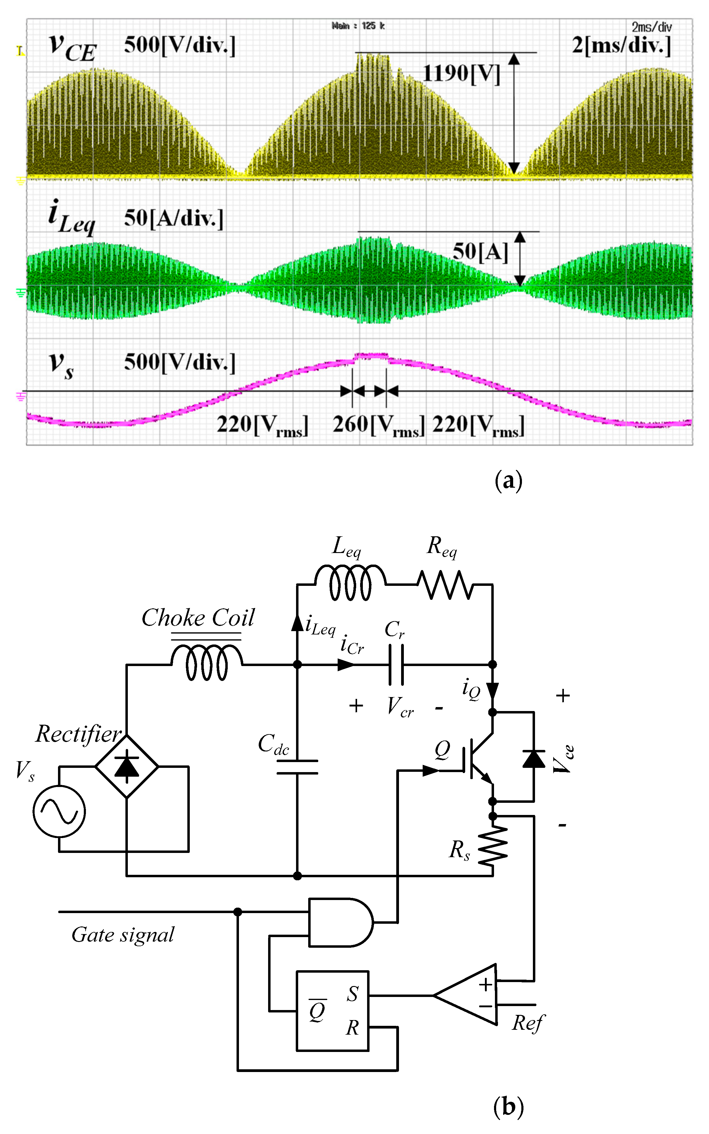
3. Results: Experimental Setup and Evaluation
4. Discussion
5. Conclusions
Author Contributions
Funding
Conflicts of Interest
References
- Dawson, F.; Jain, P. A comparison of load commutated inverter systems for induction heating and melting applications. IEEE Trans. Power Electron. 1991, 6, 430–441. [Google Scholar] [CrossRef]
- Bi, C.; Lu, H.; Jia, K.; Hu, J.; Li, H. A Novel Multiple-Frequency Resonant Inverter for Induction Heating Applications. IEEE Trans. Power Electron. 2016, 31, 8162–8171. [Google Scholar] [CrossRef]
- Kim, D.; So, J.; Kim, D. Study on Heating Performance Improvement of Practical Induction Heating Rice Cooker with Magnetic Flux Concentrator. IEEE Trans. Appl. Supercond. 2016, 26, 1–4. [Google Scholar] [CrossRef]
- Bhasme, N.R.; Mandval, B. Topologies of Voltage Source Inverter for Domestic Induction Heating. J. Sci. Eng. Res. 2015, 6, 121–126. [Google Scholar]
- Yeon, J.; Park, M.; Cho, K.; Kim, H. Field stop shorted anode trench IGBT for induction heating appliances. In Proceedings of the 38th Annual Conference on IEEE Industrial Electronics Society (IECON 2012), Montreal, QC, Canada, 25–28 October 2012; pp. 422–426. [Google Scholar] [CrossRef]
- Yeon, J.; Park, M.; Cho, K.; Kim, H. A new high voltage shorted-anode IGBT with intrinsic body diode improves performance of single-ended induction cooker. In Proceedings of the 15th European Conference on Power Electronics and Applications (EPE 2013), Lille, France, 2–6 September 2013; pp. 1–9. [Google Scholar] [CrossRef]
- Crisafulli, V. New IHR Field Stop II IGBT technology, the best efficiency for high frequency Induction Cooking Applications. In Proceedings of the International Exhibition and Conference for Power Electronics, Intelligent Motion, Renewable Energy and Energy Management (PCIM Europe 2014), Nuremberg, Germany, 20–22 May 2014; pp. 873–880. [Google Scholar]
- Tanimatsd, H.; Ahmed, T.; Hirota, I.; Yasui, K.; Iwai, T.; Omori, H.; Ahmed, N.; Lee, H.; Nakaoka, M. Two-switch boost-half bridge and boost active clamped ZVS-PWM AC-AC converters for consumer high frequency induction heater. In Proceedings of the Twentieth Annual IEEE Applied Power Electronics Conference and Exposition (APEC 2005), Austin, TX, USA, 6–10 March 2005; Volume 2, pp. 1124–1130. [Google Scholar] [CrossRef]
- Pérez-Tarragona, M.; Sarnago, H.; Lucía, Ó.; Burdío, J. Design and Experimental Analysis of PFC Rectifiers for Domestic Induction Heating Applications. IEEE Trans. Power Electron. 2018, 33, 6582–6594. [Google Scholar] [CrossRef]
- Fairchild Semiconductor. Induction Heating System Topology Review, AN-9012, Rev 1.0.4 12/18/13; Fairchild Semiconductor: Sunnyvale, CA, USA, 2000. [Google Scholar]
- Yeon, J.; Cho, K.; Kim, H. A 3.6 kW Single-ended Resonant Inverter for Induction Heating Applications. In Proceedings of the 17th European Conference on Power Electronics and Applications (EPE’15 ECCE-Europe), Geneva, Switzerland, 8–10 September 2015; pp. 1–7. [Google Scholar] [CrossRef]
- Sarnago, H.; Lucía, O.; Mediano, A.; Burdío, J.M. A Class-E Direct AC–AC Converter With Multicycle Modulation for Induction Heating Systems. IEEE Trans. Ind. Electron. 2014, 61, 2521–2530. [Google Scholar] [CrossRef]
- Lucia, O.; Burdio, J.; Millan, I.; Acero, J.; Puyal, D. Load-Adaptive Control Algorithm of Half-Bridge Series Resonant Inverter for Domestic Induction Heating. IEEE Trans. Ind. Electron. 2009, 56, 3106–3116. [Google Scholar] [CrossRef]
- Kim, C. Minimization of Abnormal Output Voltage Rising for LLC Resonant Converter at Very Light Load. IEEE Trans. Ind. Electron. 2019, 67, 1–9. [Google Scholar] [CrossRef]
- Cai, M.; Wasynczuk, O.; Saeedifard, M. A Voltage- Edge-Rate-Limiting Soft-Switching Inverter Based on Auxiliary Resonant Pole. IEEE J. Emerg. Sel. Top. Power Electron. 2019, 7, 736–744. [Google Scholar] [CrossRef]
- Divan, D.; Skibinski, G. Zero-Switching-Loss Inverters for High-Power Applications. IEEE Trans. Ind. Appl. 1989, 25, 634–643. [Google Scholar] [CrossRef]
- Kim, H.; Leu, C.; Farrington, R.; Lee, F. Clamp Mode Zero-Voltage-Switched Multi-Resonant Converters. In Proceedings of the 23rd Annual IEEE Power Electronics Specialists Conference (PESC 1992), Toledo, Spain, 29 June–3 July 1992; pp. 18–24. [Google Scholar] [CrossRef]
- Lee, D.; Hyun, D. A new hybrid Control Scheme Using Active-Clamped Class-E Inverter with Induction Heating Jar for High Power Application. In Proceedings of the 17th Annual IEEE Applied Power Electronics Conference and Exposition (APEC 2002), Dallas, TX, USA, 10–14 March 2002; Volume 2, pp. 1148–1153. [Google Scholar] [CrossRef]
- Park, N.; Lee, D.; Hyun, D. A Study on the New Control Scheme of Class-E Inverter for IH-Jar Application with Clamped Voltage Characteristics Using Pulse Frequency Modulation. IET Electr. Power Appl. 2007, 1, 433–438. [Google Scholar] [CrossRef]
- Kranprakon, P.; Sangswang, A.; Naetiladdanon, S. Model predictive control of LLC resonant inverter for induction furnace. In Proceedings of the 2017 International Electrical Engineering Congress (IEECON), Pattaya, Thailand, 8–10 March 2017; pp. 1–4. [Google Scholar] [CrossRef]
- Oh, Y.; Yeon, J.; Cho, K.; Kim, H. Resonant voltage limiting technique of single-ended resonant inverter for induction heating. Electron. Lett. 2017, 53, 804–806. [Google Scholar] [CrossRef]
- Oh, Y.; Cho, K. Load State Detection Method of the Single-Ended Resonant Inverter for the Induction Heating Rice Cooker. J. Korean Inst. Inf. Technol. 2020, 18, 43–54. [Google Scholar] [CrossRef]


| Parameter | Value |
|---|---|
| Rated source voltage | 220 [V] |
| Rated source current | 6.14 [A] |
| Rated input power | 1350 [W] |
| Ratings of bridge diode | 600 [V]/15 [A] |
| Inductance of chock coil | 660 [μH] |
| Capacitance of Cr | 0.22 [μF] |
| Inductance of Leq | 90 [μH] |
| Resistance of Req | 4 [Ω] |
| Frequency of fs | 24–50 [kHz] |
| Ratings of switching IGBT | 1350 [V]/30 [A] |
Publisher’s Note: MDPI stays neutral with regard to jurisdictional claims in published maps and institutional affiliations. |
© 2021 by the authors. Licensee MDPI, Basel, Switzerland. This article is an open access article distributed under the terms and conditions of the Creative Commons Attribution (CC BY) license (https://creativecommons.org/licenses/by/4.0/).
Share and Cite
Oh, Y.; Yeon, J.; Kang, J.; Galkin, I.; Oh, W.; Cho, K. Sensorless Control of Voltage Peaks in Class-E Single-Ended Resonant Inverter for Induction Heating Rice Cooker. Energies 2021, 14, 4545. https://doi.org/10.3390/en14154545
Oh Y, Yeon J, Kang J, Galkin I, Oh W, Cho K. Sensorless Control of Voltage Peaks in Class-E Single-Ended Resonant Inverter for Induction Heating Rice Cooker. Energies. 2021; 14(15):4545. https://doi.org/10.3390/en14154545
Chicago/Turabian StyleOh, Yongseung, Jaeeul Yeon, Jayoon Kang, Ilya Galkin, Wonsoek Oh, and Kyumin Cho. 2021. "Sensorless Control of Voltage Peaks in Class-E Single-Ended Resonant Inverter for Induction Heating Rice Cooker" Energies 14, no. 15: 4545. https://doi.org/10.3390/en14154545
APA StyleOh, Y., Yeon, J., Kang, J., Galkin, I., Oh, W., & Cho, K. (2021). Sensorless Control of Voltage Peaks in Class-E Single-Ended Resonant Inverter for Induction Heating Rice Cooker. Energies, 14(15), 4545. https://doi.org/10.3390/en14154545