Article

A Synergetic Sliding Mode Controller Applied to Direct Field-Oriented Control of Induction Generator-Based Variable Speed Dual-Rotor Wind Turbines

1
Department of Electrical and Electronics Engineering, Faculty of Engineering and Architecture, Nisantasi University, 34481742 Istanbul, Turkey
2
Faculty of Electronics, Communication and Computers, University of Pitesti, 110040 Pitesti, Romania
3
Doctoral School, Polytechnic University of Bucharest, 060042 Bucharest, Romania
*
Author to whom correspondence should be addressed.
Energies 2021, 14(15), 4437; https://doi.org/10.3390/en14154437
Submission received: 3 June 2021 / Revised: 14 July 2021 / Accepted: 16 July 2021 / Published: 22 July 2021
(This article belongs to the Collection Featured Papers in Electrical Power and Energy System)

Abstract

:
A synergetic sliding mode (SSM) approach is designed to address the drawbacks of the direct field-oriented control (DFOC) of the induction generators (IGs) integrated into variable speed dual-rotor wind power (DRWP) systems with the maximum power point tracking (MPPT) technique. Using SSM controllers in the DFOC strategy, the active power, electromagnetic torque, and reactive power ripples are reduced compared to traditional DFOC using proportional-integral (PI) controllers. This proposed strategy, associated with SSM controllers, produces efficient state estimation. The effectiveness of the designed DFOC strategy has been evaluated on variable speed DRWP systems with the MPPT technique.

1. Introduction

Induction generators have many advantages including low maintenance, high dynamic response, easy control, better speed versus torque characteristics, high efficiency, minimized weight, and more compact construction. Due to their mechanical features and favorable electricals, induction generators are widely used in the industrial sector, pumps, the military, automotive applications, and wind power [1]. Consequently, many works have been developed to enhance the effectiveness of induction generators [2,3,4]. Various control techniques for induction generators have been proposed in [5]. The most common methods are based on DC-link voltage control [6], space vector control in [7], and direct torque control (DTC) [8]. Most of the presented techniques for power control of induction generators are based on pulse-width modulation (PWM) and use proportional-integral (PI) regulators. There is another strategy similar to DTC control that relies on direct control of the reactive and active power of the induction generator, and this is by using two hysteresis controllers and one lookup table [9]. In [10], the reactive and active power ripple minimization is achieved by using neural algorithms. In this proposed method, both the lookup table and the hysteresis comparators were replaced by neural networks. The simulation results show the performances of the designed strategy. For controlling induction generators, two converters should be used. One such converter is the rotor side converter (RSC), which controls the reactive and active power exchanged between the induction generator stator and the network. The grids side converter (GSC) which controls the voltage and reactive power exchanged between the rotor and the network. Generally, the induction generators are driven by a rectifier and a classical inverter each containing six thyristors type inductors. Two different methods can be used or the same method to control both the classical inverter (RSC) and the rectifier (GSC). In [11], a three-switch three-phase inverter controlled by field-oriented control (FOC) strategy using traditional PI regulators for an induction generator-based wind turbine is presented. In [12], the direct FOC strategy of induction generators is proposed, this strategy controls the reactive and active power through a simple modulation technique of a three-phase inverter. Direct FOC technique is a control strategy in which is indirectly selected output voltage vector states based on the active and reactive power fluctuations using PI regulators and with using the current loop. The indirect FOC strategy is presented in [13], the principle indirect FOC strategy is to control the active and reactive powers by using four PI regulators. In [14] the indirect FOC strategy reduces a more harmonic distortion (THD) of voltage compared to the direct FOC method of induction generators.
In this work, we will focus on applying the direct FOC method to the induction generators and improving their effectiveness. On the other hand, the direct FOC method is a simpler structure and easy to apply. One of the main disadvantages of this technique is that its effectiveness depends highly on accurate induction generator parameters such as rotor, stator inductances, and resistances. Another disadvantage of the direct FOC strategy is the highly active and reactive power ripples [15]. For minimizing active and reactive power ripples, several techniques have been designed for reducing these drawbacks. A novel direct FOC strategy utilizing the fuzzy logic controllers has been proposed in order to control torque, reactive and active power of induction generator in [16]. A novel direct FOC strategy end with neural algorithms has been designed in [17]; the traditional PI controllers were replaced by neural networks, thus lowering the effect of the DC-link voltage on commutation reactive and active power minimization to some extent. The direct FOC method and traditional space vector modulation (SVM) technique is combined to control of the induction generator-based wind power [18]. For effectively reducing the reactive and active power undulations, the sliding mode controllers (SMCs) are used to apply the controlled direct and quadrature rotor voltages from the replaced traditional PI controllers by robust control based on SMC technique [19]. Additionally, commutation active and reactive power ripple minimization by using neuro-fuzzy algorithms is designed in [20]. In the direct FOC strategy, real active and reactive power measurement is variable in practice. The feedback of active and reactive power control is susceptible to many factors, including model accuracy, parameter changes, etc., because the algorithm estimation is mutually exclusive. However, in direct FOC strategy, it is easy to measure the actual values of the control variables by measuring the rotor current and rotor voltage in a real system; therefore, this work proposes induction generators controlled by direct FOC strategy using a new nonlinear control theory for variable speed dual-rotor wind power (DRWP) systems with the maximum power point tracking (MPPT) technique. Direct FOC strategy with synergetic sliding mode controllers minimizes the cost of drive because it decreases the reactive and active power undulations. Moreover, in this work, by reducing the chattering phenomenon and using the modified SVM technique, the cost of an induction generator drive can be more minimized. The main contributions of the work are listed below:
1.
This work designed a robust direct FOC method of induction generator-based DRWP systems;
2.
A new robust control to reactive and active power ripples minimization for direct FOC method is designed;
3.
Synergetic sliding mode controllers to minimize error tracking reactive and active power references of induction generator-based DRWP systems;
4.
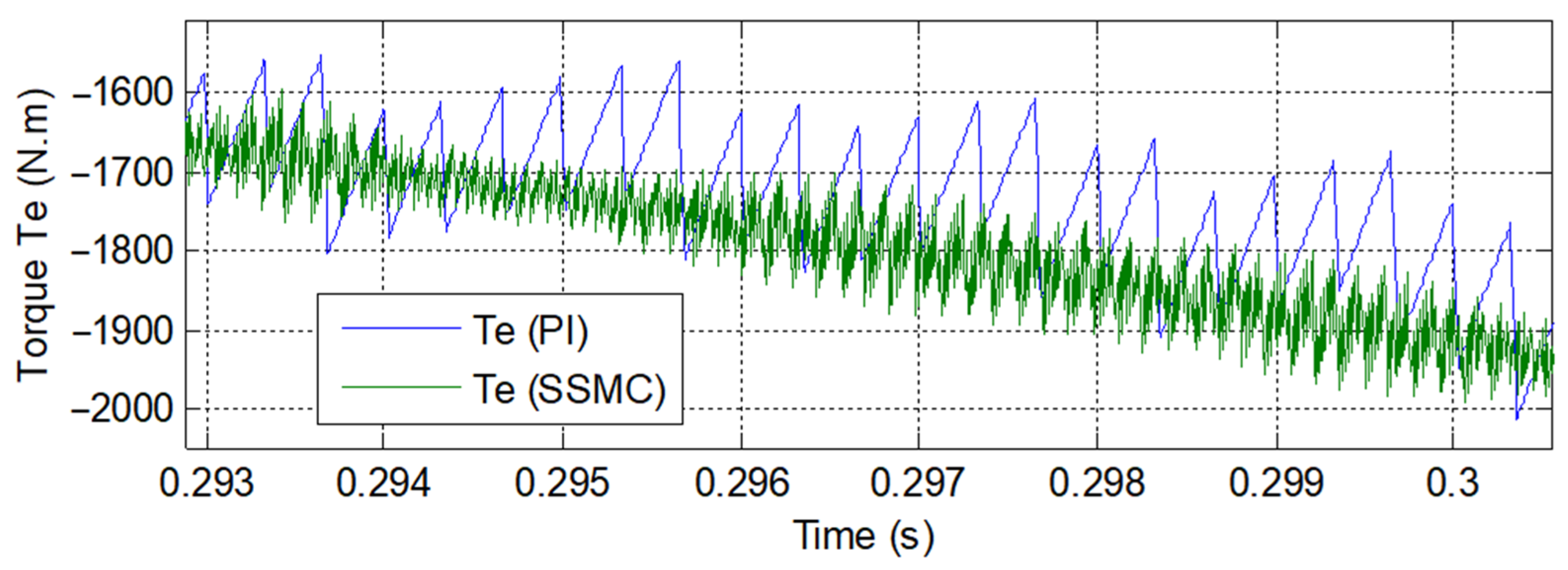
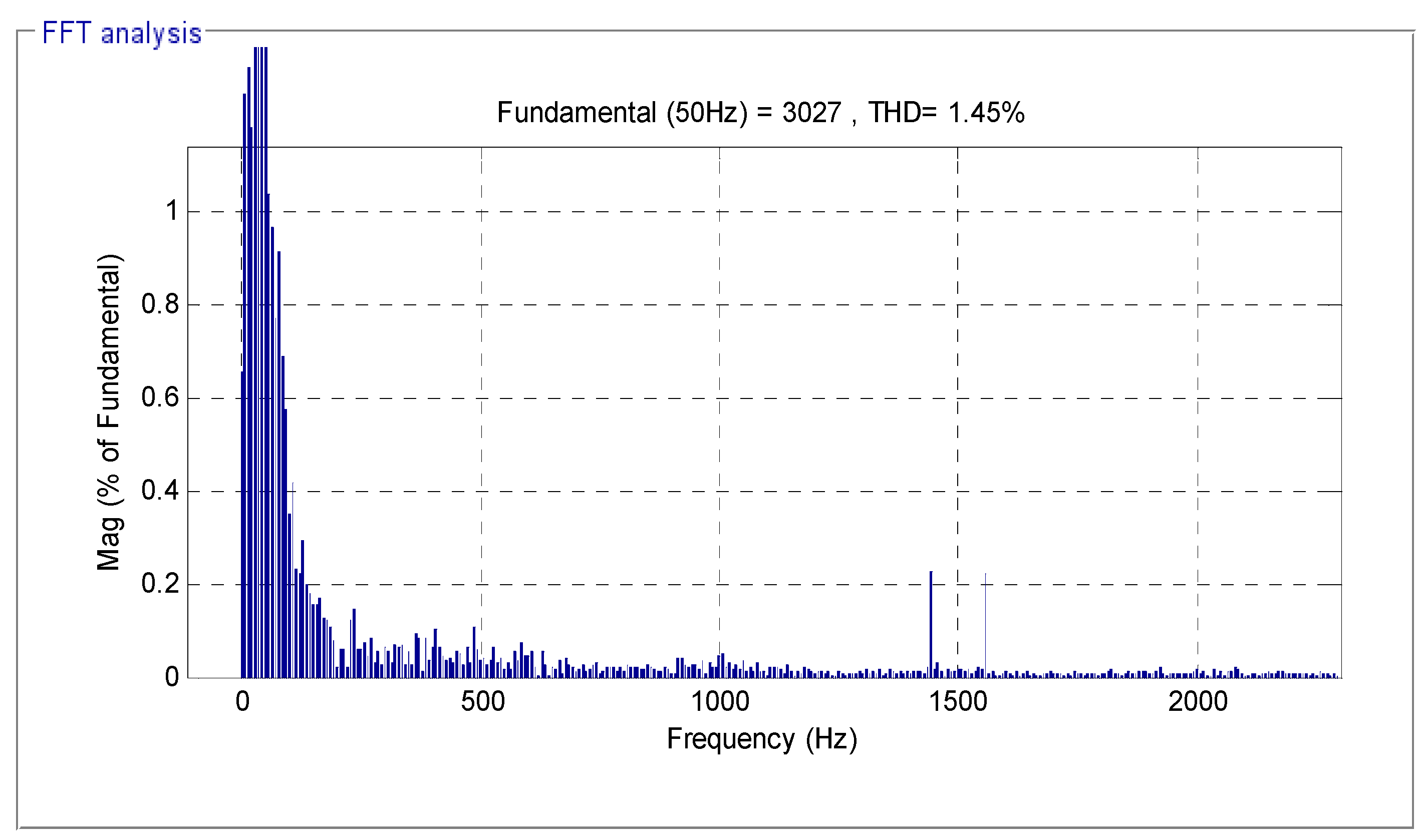
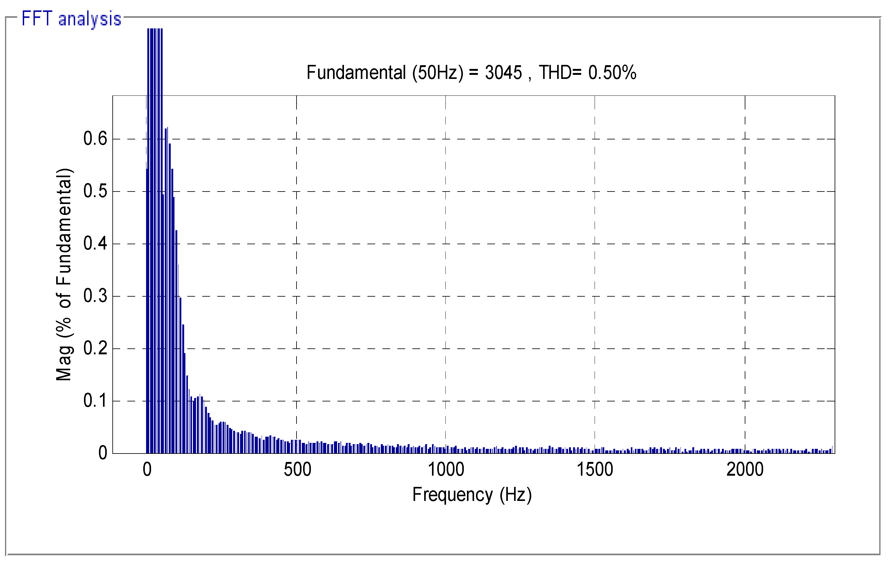
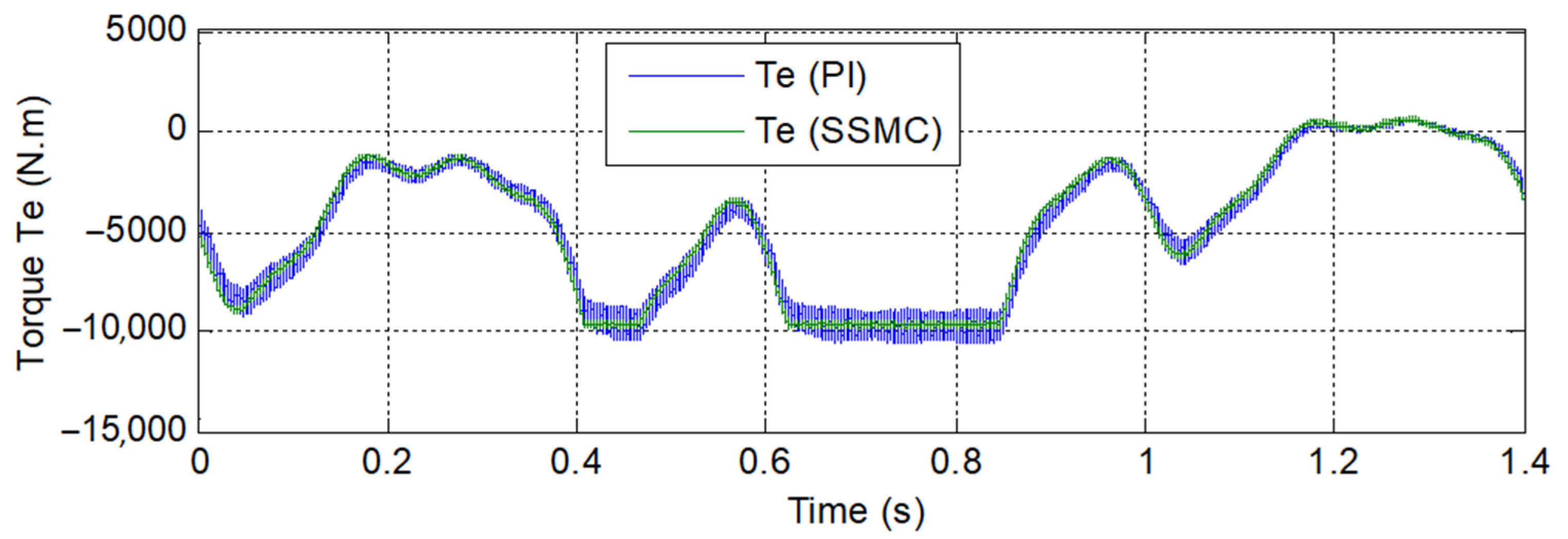
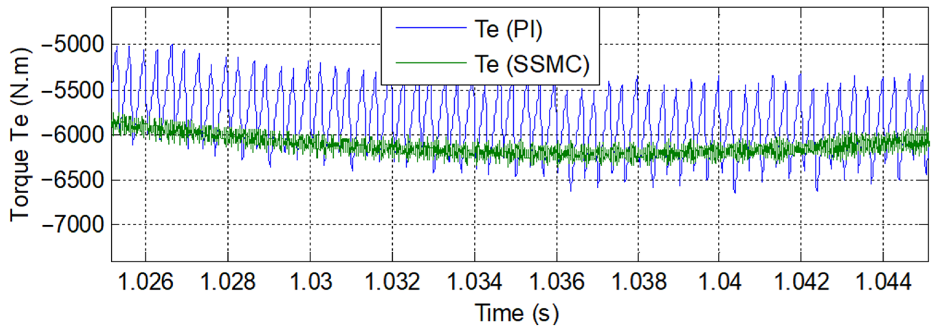
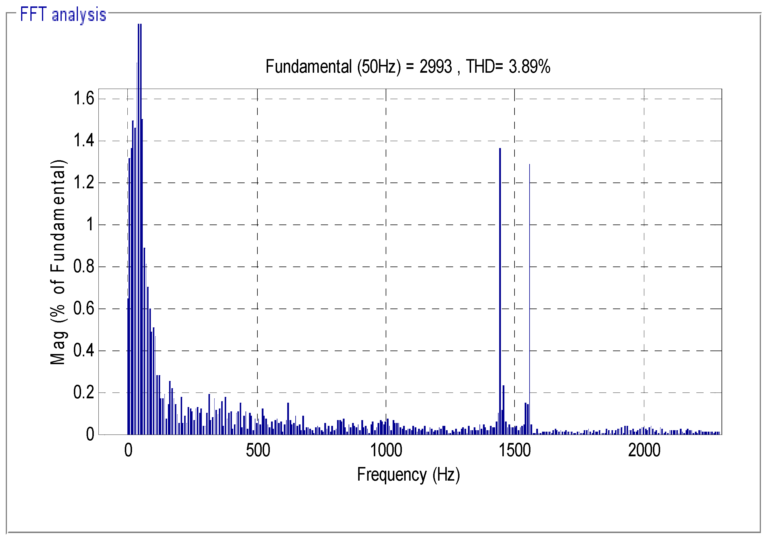
Using the proposed technique and modified SVM technique minimizes the THD of voltage and torque ripple of the induction generator-based DRWP systems.
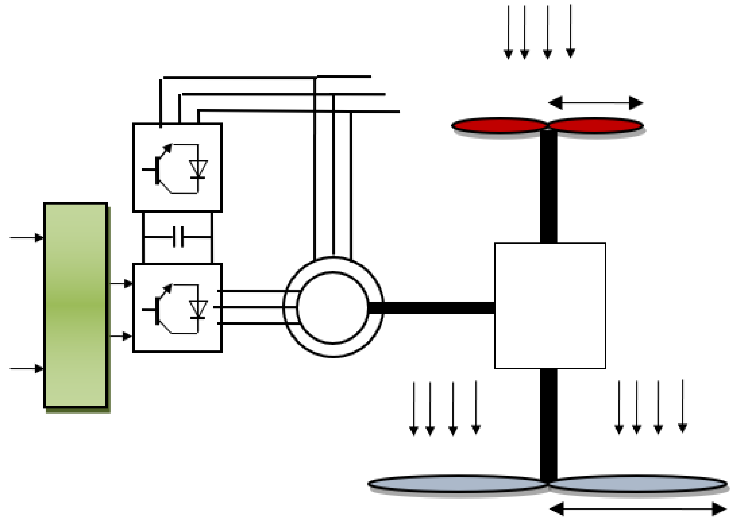
This work is organized as follows. Section 2 points out necessary equations related to the mathematical modeling of the DRWP system. Synergetic sliding mode control theory is presented in Section 3. Section 4 explains the designed robust direct FOC method for induction generators. Matlab software-based simulation studies is presented in Section 5. The conclusion is given in Section 6.

2. DRWP Model

DRWP is a turbine with two rotors. It aims to improve the effectiveness of the classical wind turbine and minimize the power generated from traditional sources based on fossil fuels, such as coal, oil, and natural gas, even if the wind is highly variable [21]. Double rotor wind turbines have two rotors rotating in opposite directions on the same axis [22]. DRWP is a new technology of wind power that has been designed to increase the production of mechanical energy (See Figure 1).
The number of mechanical components in DRWP is higher than in the classical wind turbine. This new technology has been studied in several works [23]. This new technology has an excellent performance in regions with low and high wind speeds. Among its advantages is that it operates at lower tip-speed ratios compared to the classical wind turbine [24]. This method has several drawbacks, for example, high financial cost, difficulty to control, and a risk of subsynchronous resonance. It contains a large number of mechanical components compared to SRWP systems. On the other hand, we use the MPPT technique to control the DRWP system, such as a traditional wind turbine. There are several methods in order to track the maximum power point (MPP) and the global MPP or the global maximum efficiency point (GMEP) [25]. Equation (1) represents the aerodynamic mechanical power resulting from the DRWP system [26]:
P D R W P = P T = P M R + P A R
where PAR, PMR the aerodynamic mechanical power of the auxiliary and main rotors.
In the DRWP system, the resulting aerodynamic torque is the sum of the aerodynamic torques of the auxiliary and main rotor, and is represented by the following equations:
T D R W P = T M R + T A R
where TAR, TMR the aerodynamic torque of the auxiliary and main rotors.
The aerodynamic torque of the auxiliary and main rotor is given by Equations (3) and (4), respectively [24].
T A R = C p 2 λ A R 3 ρ · π · R A R 5 · w A R 2
T M R = C p 2 λ M R 3 ρ · π · R M R 5 · w M R 2
where ρ: the air density, RMR, RAR: Blade radius of the auxiliary and main rotors, λAR, λMR: the tip-speed ratio of the main and auxiliary rotors, and wAR, wMR: the mechanical speed of the auxiliary and main rotors. The Cp is given:
C p ( λ , β ) = 1 λ + 0.08 . β 0.035 β 3 + 1                      
where β is pitch angle.
Equation (6) represents the tip-speed ratios of the auxiliary rotor.
λ A R = w A R . R A R V 1      
with V1 is the wind speed on an auxiliary rotor.
Equation (7) represents the tip-speed ratios of the main rotor.
λ M R = w M R · R M R V M R    
where VMR is the speed of the unified wind on main rotor.
Equation (8) represents the wind speed in the main turbine. The distance between the auxiliary and the main rotors is 15 m [26].
V x = V 1 · ( 1 1 ( 1 C T ) 2 ( 1 + 2 x 1 + 4 x 2 ) )      
where x: the non-dimensional distance from the auxiliary rotor disk, Vx: is the velocity of the disturbed wind between rotors at point x, and CT: the trust coefficient (CT = 0.9).

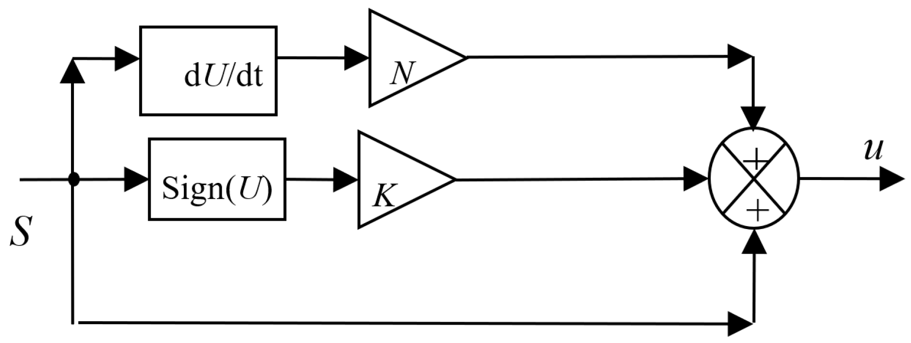
3. Synergetic Sliding Mode Control Theory

In this part, we proposed a new technique based on the combination of synergistic control and sliding mode control (SMC), intending to create a more robust method and reducing the chattering phenomenon. The proposed technique is to improve the performance of the sliding mode control by replacing the control equivalent portion (ueq(t)) with the synergetic control.
The structure of a sliding mode control consists of two sections, one concerning the exact linearization (ueq) and the other stabilizing (un). Equation (9) represents the principle of the SMC method [27].
u = u e q ( t ) + u n ( t )      
with:
u n ( t ) = K · s i g n ( S )  
where S is the linear sliding surface.
Synergistic control is a type of variable structure control. It differs from sliding mode control in the way it forces the sliding surface to fall to zero. Equation (11) represents the principle of the synergetic control theory [26,27,28,29].
S + N · d S d t = 0                
N is the convergence speed (N > 0).
Substituting the exact linearization into the SMC method using Equation (11), we obtain a new nonlinear method called synergetic sliding mode control (SSMC). This proposed strategy is a simpler algorithm and more robust compared to the classical SMC method. On the other hand, this proposed strategy does not need the mathematical model of the system. Equation (12) represents the principle of the proposed SSMC control theory (see Figure 2):
u ( t ) = S + N · d S d t K · s i g n ( S )                
where K is the positive gain.
The following will ensure the stability of the SSMC controller based on Lyapunov theorem: S(0) = 0 and S(x)∙x > 0 for all x ≠ 0. The dynamics and stability of the system controlled by the proposed method can be ensured by appropriately setting the values for parameters N and K. The reaching condition is given by the following equation:
S ( x ) ·   S ˙ ( x ) 0      

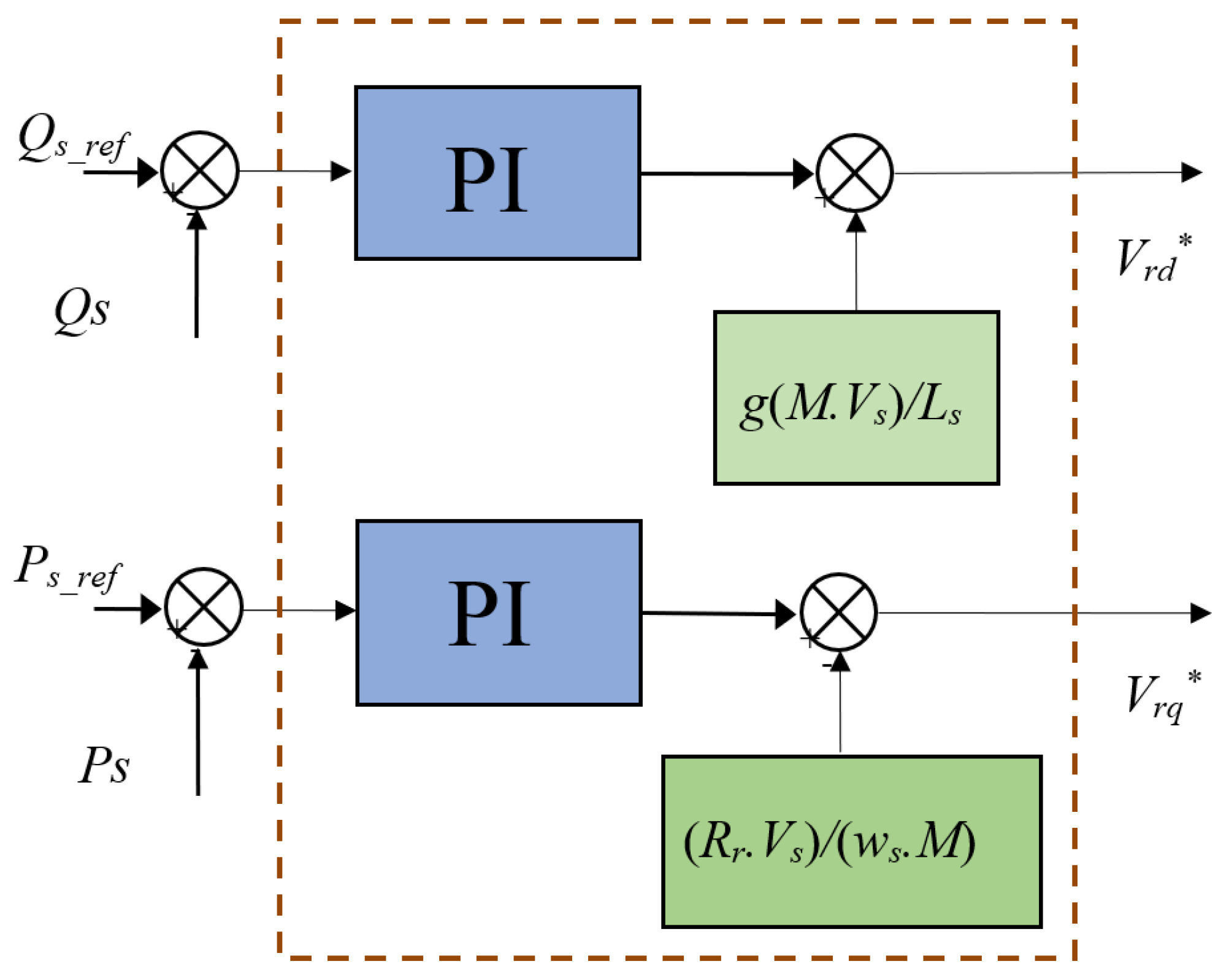
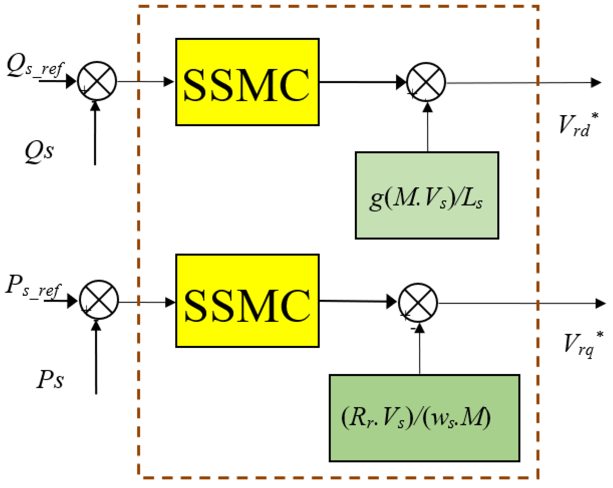
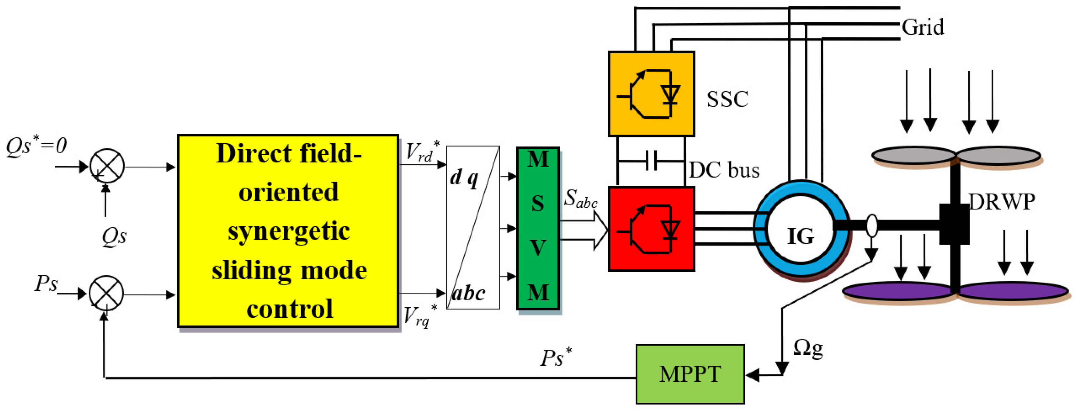
4. Direct FOC Method with SSMC Controllers

FOC is one of the most popular methods applied to rotating electrical machines, and this is because of its characteristics compared to some of the controls. The principle of the FOC technique is to orient the stator flux along the axis of the rotating frame. There are several applications to this method, for example, the asynchronous motor [30], the synchronous motor [31], and multiphase machines [32]. There are two types of this method: the direct FOC method and the indirect FOC method. The direct FOC method is simpler (using simple calculations) and can be accomplished easily compared to the indirect FOC method. However, despite these advantages, the direct FOC method gives the most fluctuations in the reactive and active powers. On the other hand, the direct FOC method gives more THD of stator voltage and current compared to the indirect FOC control technique [33]. The principle of operation of the direct method is illustrated in the following scientific works [34,35,36,37,38,39]. In [35], the indirect FOC (IFOC) method improved the performance of the induction generator compared with the direct FOC (DFOC) strategy. In [36], the DFOC strategy was designed based on the super twisting algorithms to regulate the torque and speed of the six-phase induction motor. The experimental result shows the superiority of the designed DFOC strategy. In [37], the DFOC technique was designed based on an intelligent SVM method to minimize the active power and torque undulations of ASG-based SRWP systems. In [38], the FOC technique was designed based on maximum torque per ampere to minimize the coper losses of the system of the permanent magnet-assisted synchronous reluctance motor. FOC method and flatness approach were combined to control the permanent synchronous motor using the dSPACE controller [39]. The experimental and simulation results show the superiority of the proposed FOC method. To ensure the decoupling between control axes, a DFOC strategy was applied [23] by aligning the stator flux with the direct axis d.
ψ d s = ψ s   and   ψ q s = 0
The stator voltage can be expressed by:
{ V d s = 0 V q s = V s = w s · ψ s
The expressions of stator current are defined by:
{ I d s = M L s I d r + ψ s L s I q s = M L s I q r
The reactive and active powers is achieved through the control of the induction generator rotor currents
{ P s = 3 2 ω s ψ s M L s I q r Q s = 3 2 ( ω s ψ s M L s I d r ω s ψ s 2 L s )
The electromagnetic torque equation is:
T e m = 3 2 p M L s I q r ψ d s
The direct and quadrature rotor voltages can be expressed [23]:
{ V d r = R d r · I d r + ( L r M 2 L s ) p · I d r g · w s ( L r M 2 L s ) I q r V q r = R d r · I q r + ( L r M 2 L s ) p · I q r g · w s ( L r M 2 L s ) I d r + g M · V s L s
Equation (20) represents the relationship between the rotor voltages and the rotor currents [12].
{ V d r = R d r · I d r g · w s ( L r M 2 L s ) I q r V q r = R d r · I q r g · w s ( L r M 2 L s ) I d r + g M · V s L s
The rotor current has the expression:
{ I d r = ( V d r g · w s ( L r M 2 L s ) I q r ) 1 R r + ( L r M 2 L s ) p I q r = ( V q r g · w s ( L r M 2 L s ) I q r g M · V s L s ) 1 R r + ( L r M 2 L s ) p
Figure 3 depicts the induction generator active and reactive powers control based on direct FOC technique, where two independent PI controllers are used for each control axis.
In order to improve the effectiveness of the traditional direct FOC technique, the standard PI controllers will be replaced by two robust controls based on the SSMC controller. The reactive and active power estimation block keeps the same shape as that established for the traditional direct FOC method, described in the previous work [35]. In this robust direct FOC technique, the reactive and active power are controlled by two SSMC controllers, while the modified SVM technique replaces the traditional PWM strategy. This control by direct FOC-SSMC has the advantages of vector control and conventional direct FOC method to overcome the problem of fluctuations in power and is generated by the induction generators. SSMC controllers and the MSVM technique are used to obtain a fixed switching frequency and less pulsation of the powers. The principle of the direct FOC-SSMC control technique is the direct regulation of the reactive and active powers of the induction generator-based DRWP system, by using two SSMC controllers. The two controlled variables are active and reactive powers, which are usually regulated by the proposed SSMC method. The idea is to keep the reactive and active power quantities within these sliding surfaces.
The direct FOC with the SSMC method (FOC-SSMC) is a modification of the traditional direct FOC strategy, where the PI controllers have been replaced by the SSMC method, as shown in Figure 4.
The SSMC method was proposed to force the controlled dynamics towards manifolds and keeps them there. To force the induction generator reactive and active powers to track their corresponding references, the linear sliding surfaces are selected to equal the error between the real and desired dynamics by Equations (22) and (23):
S a = P s * P s
S r = Q s * Q s  
where the surfaces are the reactive power error Sr = Qs*Qs and the active power error Sa = Ps*Ps. The linear sliding surfaces shown in (22) and (23) are used as input to the SSMC controller method control law. Stator reactive and active power SSMC method are used to influence, respectively, the direct and quadrature rotor voltage components as in (24) and (25):
V q r * = S a + N · d S a d t K · s i g n ( S a )
V d r * = S r + N · d S r d t K · s i g n ( S r )
This designed strategy is implemented for a direct FOC technique based on the SSMC method to obtain the minimum reactive power ripple and to reduce the chattering phenomenon.
The basic structure of the direct FOC-SSMC control method of the induction generator-based variable speed DRWP system using the MPPT strategy is shown in Figure 5. This designed control technique is robust, simple, and has a small response time. On the other hand, this designed control technique minimized the active and reactive power ripples compared to the traditional direct FOC, direct power control, and indirect FOC methods.

5. Numerical Simulation

The proposed SSMC controllers as applied for the induction generator active and reactive powers have been implemented using Matlab software (from MATLAB & Simulink® of MathWorks). In addition, a comparison study between the SSMC controllers with the traditional PI controllers was carried out in terms of torque, current, active and reactive power ripple minimization, wind speed changing, trajectory tracking, and robustness to induction generator parameter variations.

5.1. First Test

The simulations are carried out with a 1.5 MW induction generator attached to a 398 V/50 Hz grid. The parameters of the machine are given in Table 1.
The two direct FOC methods, direct FOC method with PI controllers and proposed direct FOC method, are simulated and compared in terms of torque, stator current, reactive and active power ripples, reference tracking, and THD value of current.
Figure 6, Figure 7, Figure 8, Figure 9, Figure 10, Figure 11, Figure 12, Figure 13 and Figure 14 show the obtained simulation results. As it is shown in Figure 6, Figure 7, Figure 8 and Figure 9, for the two direct FOC methods, the reactive and active powers track almost perfectly their reference values. On the other hand, Figure 9 shows the current of both direct FOC methods. It therefore confirms that the amplitudes of the currents depend on the state of the drive system and the value of the load active power. Figure 13 and Figure 14 show the THD value of current of the induction generator-based variable speed DRWP system with MPPT for both direct FOC methods. It can be clearly observed through these figures that the THD value is minimized for the proposed direct FOC method (0.50%) when compared to the traditional direct FOC method (1.45%).
The zoom in the active power, torque, and stator current is shown in Figure 10, Figure 11 and Figure 12, respectively. It can be seen that the proposed direct FOC method minimizes the ripples in torque, stator current, and active power compared to the traditional direct FOC method. Based on the results above, it can be said that the proposed direct FOC method has proven its efficiency in reducing ripples and chattering phenomena in addition to keeping the same advantages of the traditional direct FOC method. On the other hand, this designed control scheme minimized the THD value of stator current compared to other techniques (see Table 2, where VFDPC is the virtual flux direct power control).

5.2. Second Test

In this part, we changed the values of parameters Ls, Lr, Rs, Rr, and M, to find out which control technique is not affected by a change of parameters. The obtained results are shown in Figure 15, Figure 16, Figure 17, Figure 18, Figure 19, Figure 20, Figure 21, Figure 22 and Figure 23. Note that there is a change in active power, stator current, torque, and reactive power because both torque and current are related to the changing values of parameters. On the other hand, the classical method was greatly affected by the change of parameters compared to the proposed control scheme (Figure 19, Figure 20 and Figure 21), and this is evident in the value of THD (Figure 22 and Figure 23). Thus, it can be concluded that the direct FOC technique with proposed SSMC controllers is more robust than the traditional direct FOC technique with PI regulators.

6. Conclusions

This work presented two types of FOC method for an induction generator-based variable speed dual-rotor wind power generation system, with detailed simulation investigation and theoretical analysis. The main findings are as follows:
(1)
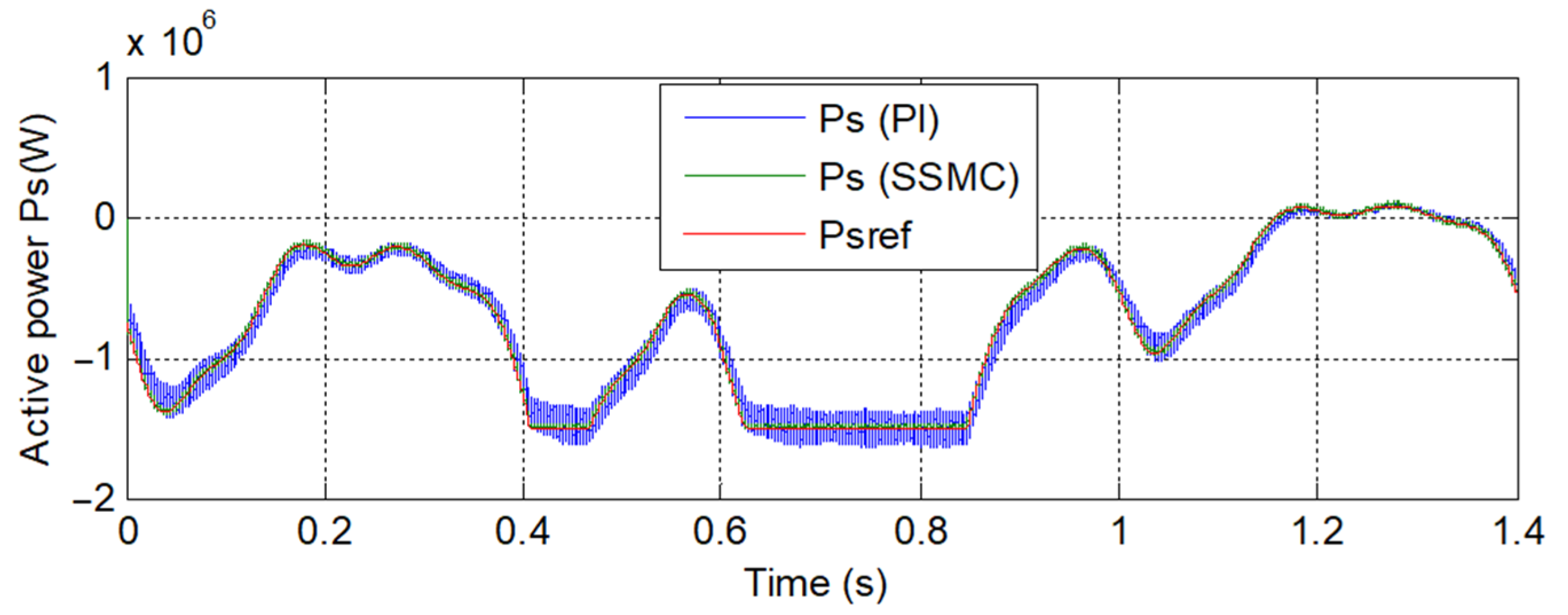
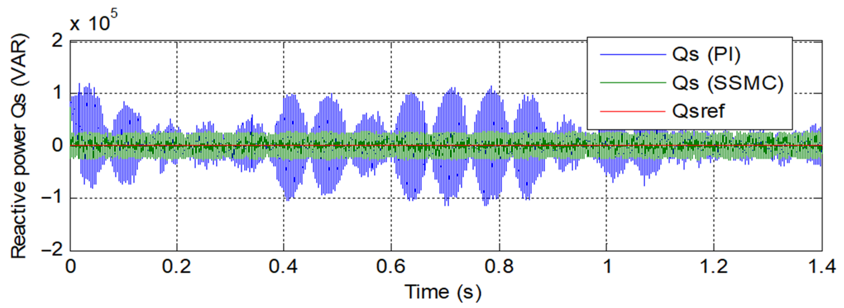
As in the direct FOC-SSMC method, active and reactive power should not be estimated; the direct FOC-SSMC method causes filter design and converter simplicity. It also improves the transient effectiveness of the controller.
(2)
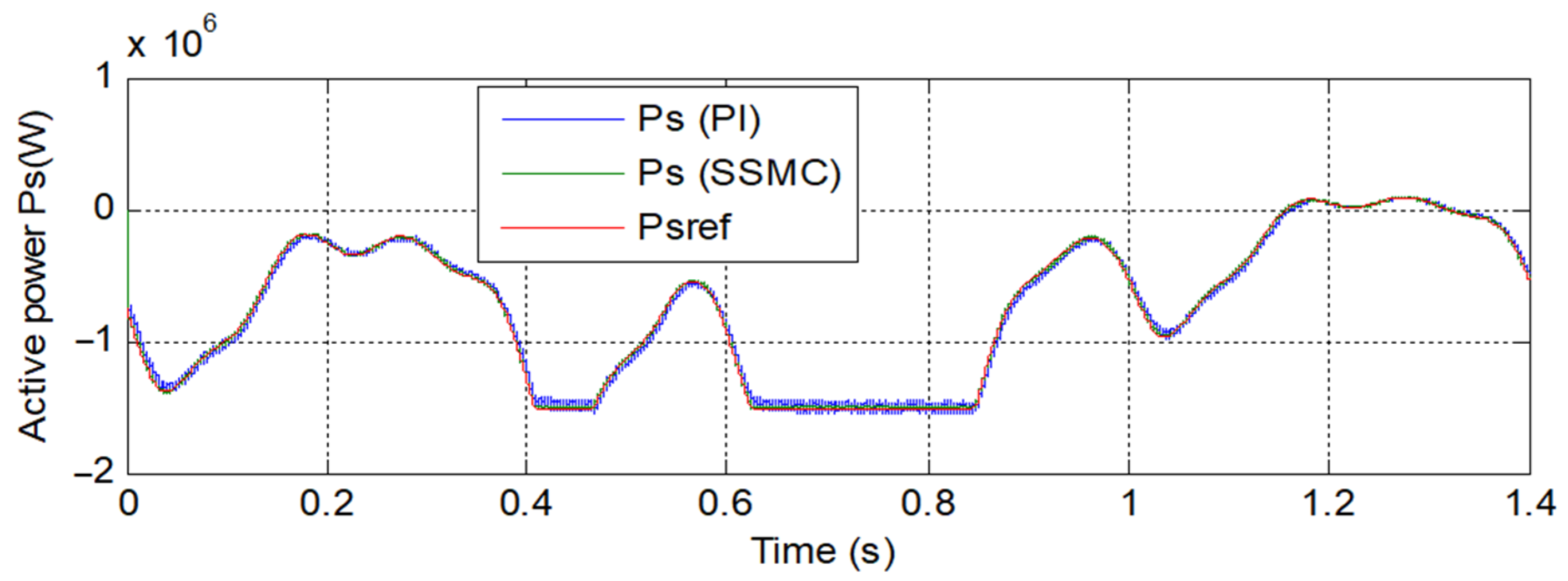
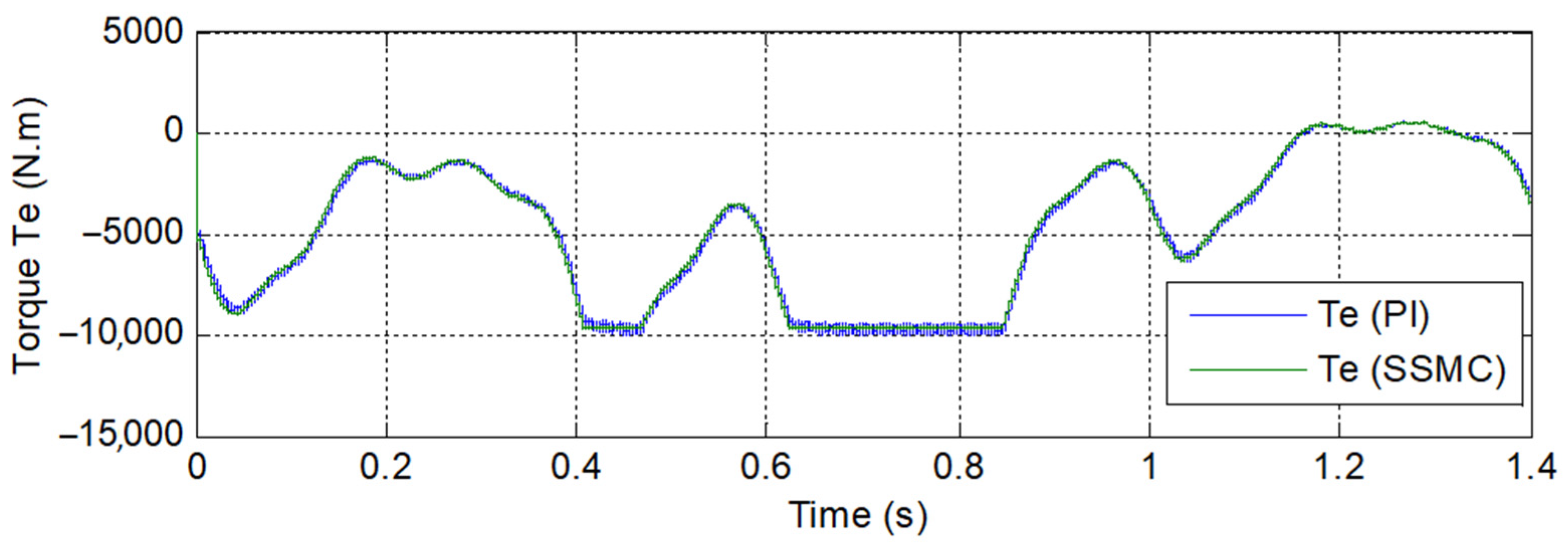
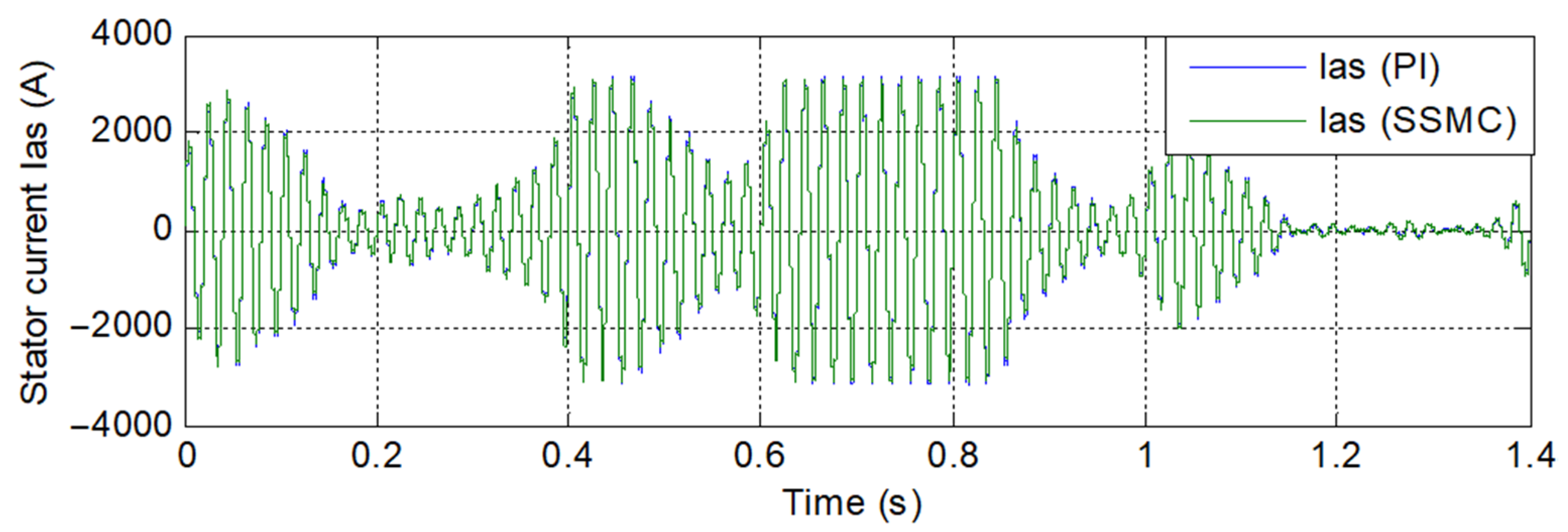
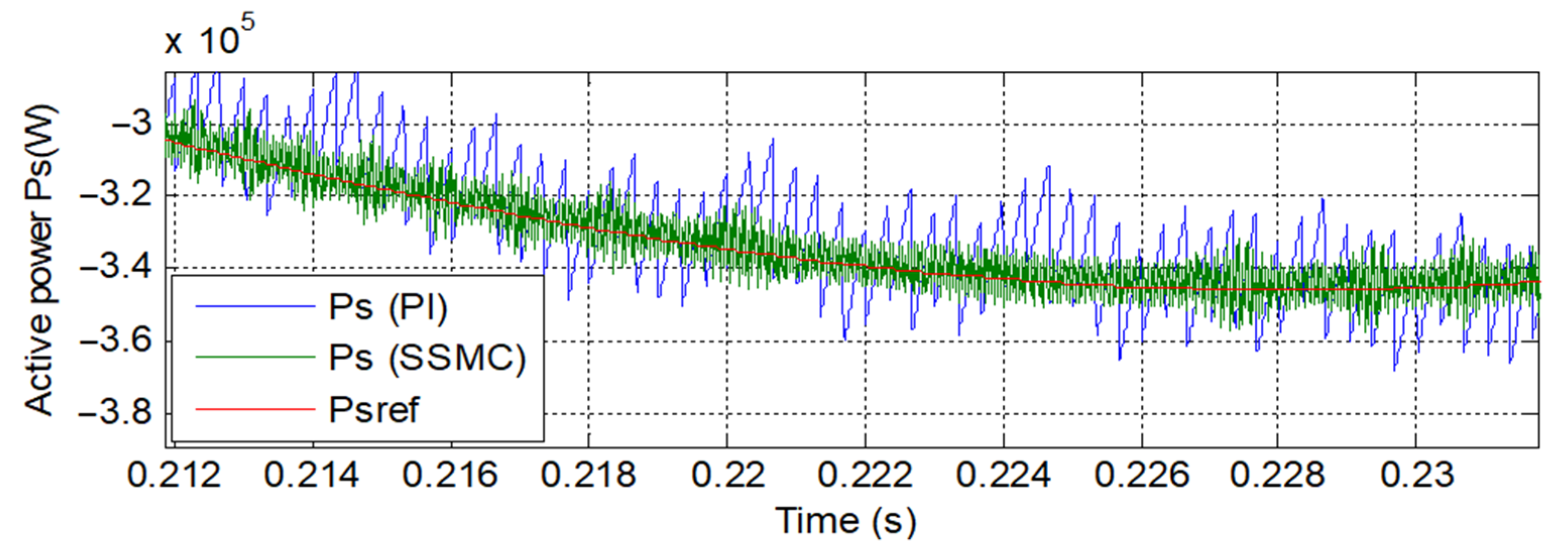
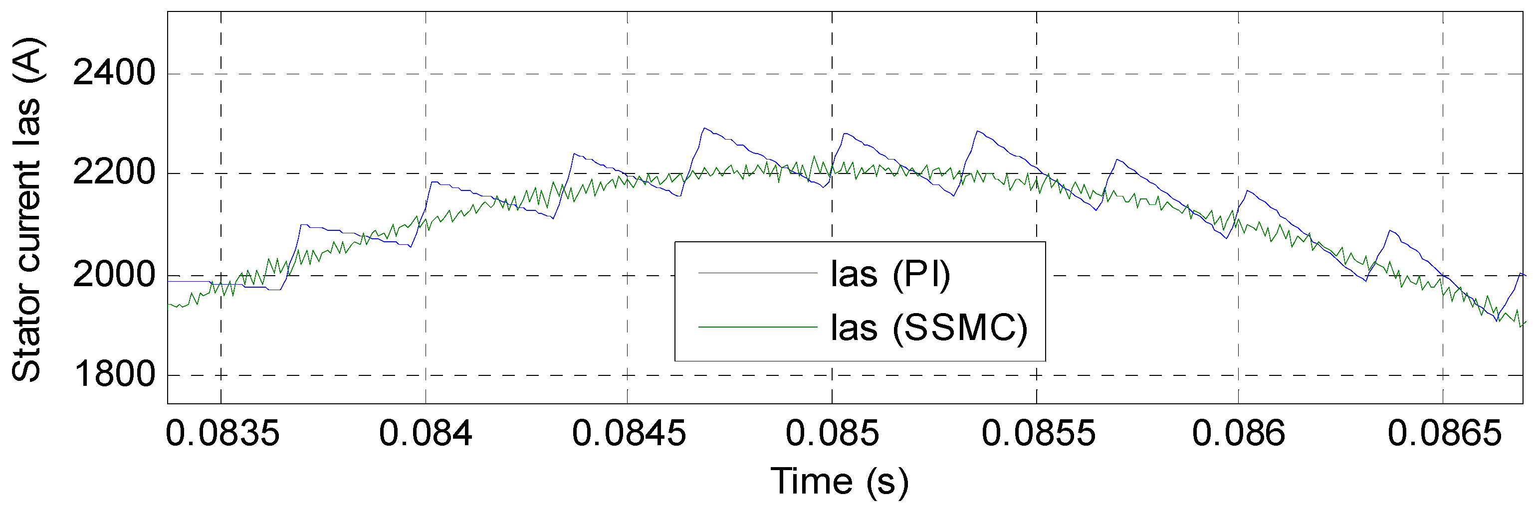
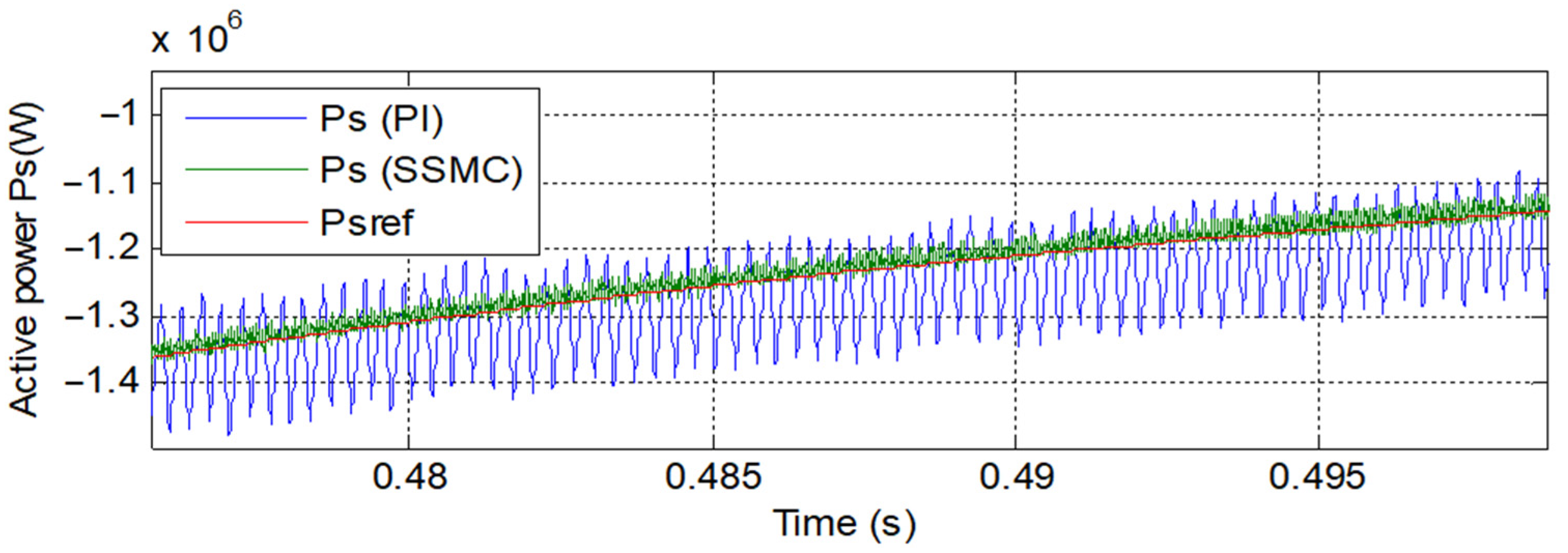
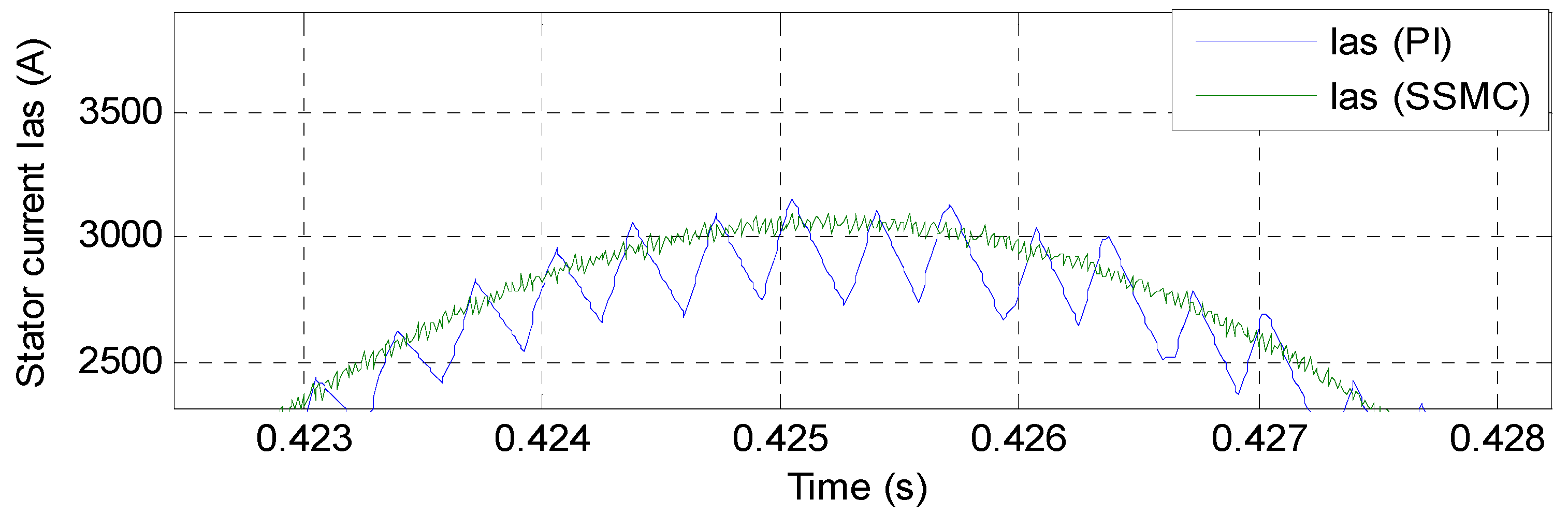
Direct FOC method gives more THD value and power ripple. There is no improved system effectiveness in comparison with the direct FOC-SSMC method.
(3)
Although the robustness of the designed method causes the use of the proposed nonlinear controllers, its characteristics, as stated in part six, such as improved dynamic and transient performance, make it a suitable controller for variable speed dual-rotor wind power production.
In conclusion, the classical and proposed direct FOC methods analyzed in this paper may differently meet the imposed performance requirements, as shown in Table 3.

Author Contributions

Conceptualization, H.B.; methodology, H.B.; software, H.B.; validation, N.B.; investigation, H.B.; resources, H.B. and N.B.; data curation, N.B.; writing—original draft preparation, H.B.; supervision, N.B.; project administration, N.B.; Formal analysis: N.B.; Funding acquisition: N.B.; Visualization: N.B.; writing—review and editing: N.B. and H.B. Both authors have read and agreed to the published version of the manuscript.

Funding

This research received no external funding.

Conflicts of Interest

The authors declare no conflict of interest.

References

  1. Marques, G.; Iacchetti, M.F. Sensorless Frequency and Voltage Control in the Stand-Alone DFIG-DC System. IEEE Trans. Ind. Electron. 2016, 64, 1949–1957. [Google Scholar] [CrossRef]
  2. Iacchetti, M.F.; Marques, G.; Perini, R. Torque Ripple Reduction in a DFIG-DC System by Resonant Current Controllers. IEEE Trans. Power Electron. 2014, 30, 4244–4254. [Google Scholar] [CrossRef] [Green Version]
  3. Kaloi, G.S.; Baloch, M.H.; Kumar, M.; Soomro, D.M.; Chauhdary, S.T.; Memon, A.A.; Ishak, D. An LVRT Scheme for Grid Connected DFIG Based WECS Using State Feedback Linearization Control Technique. Electronics 2019, 8, 777. [Google Scholar] [CrossRef] [Green Version]
  4. Worku, M.Y.; Hassan, M.; Abido, M.A. Real Time-Based under Frequency Control and Energy Management of Microgrids. Electronics 2020, 9, 1487. [Google Scholar] [CrossRef]
  5. Tian, P.; Hao, Z.; Li, Z. Doubly-Fed Induction Generator Coordination Control Strategy Compatible with Feeder Automation. Electronics 2019, 9, 18. [Google Scholar] [CrossRef] [Green Version]
  6. Hu, J.; Huang, Y.; Wang, D.; Yuan, H.; Yuan, X. Modeling of Grid-Connected DFIG-Based Wind Turbines for DC-Link Voltage Stability Analysis. IEEE Trans. Sustain. Energy 2015, 6, 1325–1336. [Google Scholar] [CrossRef]
  7. Kroplewski, P.; Morawiec, M.; Jąderko, A.; Odeh, C. Simulation Studies of Control Systems for Doubly Fed Induction Generator Supplied by the Current Source Converter. Energies 2021, 14, 1511. [Google Scholar] [CrossRef]
  8. Mondal, S.; Kastha, D. Improved Direct Torque and Reactive Power Control of a Matrix-Converter-Fed Grid-Connected Doubly Fed Induction Generator. IEEE Trans. Ind. Electron. 2015, 62, 7590–7598. [Google Scholar] [CrossRef]
  9. Mossa, M.A.; Echeikh, H.; Diab, A.A.Z.; Quynh, N.V. Effective Direct Power Control for a Sensor-Less Doubly Fed Induction Generator with a Losses Minimization Criterion. Electronics 2020, 9, 1269. [Google Scholar] [CrossRef]
  10. Benbouhenni, H. Twelve Sectors DPC Control Based on Neural Hysteresis Comparators of the DFIG Integrated to Wind Power. Tec. Ital.-Ital. J. Eng. Sci. 2020, 64, 347–353. [Google Scholar] [CrossRef]
  11. Prasad, R.M.; Mulla, M.A. A Novel Position-Sensorless Algorithm for Field-Oriented Control of DFIG with Reduced Current Sensors. IEEE Trans. Sustain. Energy 2018, 10, 1098–1108. [Google Scholar] [CrossRef]
  12. Benbouhenni, H. Reducing current and torque ripples in DVC control of DFIG operation at constant switching frequency for wind generation application. Majlesi J. Energy Manag. 2019, 8, 47–55. [Google Scholar]
  13. Benbouhenni, H. Intelligence indirect vector control of a DFIG based wind turbines. Majlesi J. Electr. Eng. 2019, 13, 27–35. [Google Scholar]
  14. Benbouhenni, H. Comparative study between different vector control methods applied to DFIG wind turbines. Majlesi J. Mechatron. Syst. 2018, 7, 15–23. [Google Scholar]
  15. Prasad, R.M.; Mulla, M.A. Mathematical Modeling and Position-Sensorless Algorithm for Stator-Side Field-Oriented Control of Rotor-Tied DFIG in Rotor Flux Reference Frame. IEEE Trans. Energy Convers. 2019, 35, 631–639. [Google Scholar] [CrossRef]
  16. Dahri, N.; Ouassaid, M.; Yousfi, D.A. FOC based robust fuzzy logic controller for a wind energy conversion system to overcome mechanical parameter uncertainties. In Proceedings of the 2020 IEEE International Autumn Meeting on Power, Electronics and Computing (ROPEC), Ixtapa, Mexico, 4–6 November 2020; pp. 1–7. [Google Scholar] [CrossRef]
  17. Ba-Razzouk, A.; Cheriti, A.; Olivier, G.; Sicard, P. Field-oriented control of induction motors using neural-network decouplers. IEEE Trans. Power Electron. 1997, 12, 752–763. [Google Scholar] [CrossRef]
  18. Malinowski, M.; Jasinski, M.T.; Kazmierkowski, M.P. Simple Direct Power Control of Three-Phase PWM Rectifier Using Space-Vector Modulation (DPC-SVM). IEEE Trans. Ind. Electron. 2004, 51, 447–454. [Google Scholar] [CrossRef]
  19. Hea-Gwang, J.; Won-Sang, K.; Kyo-Beum, L.; Byung-Chang, J.; Seung-Ho, S. A sliding-mode approach to control the active and reactive powers for A DFIG in wind turbines. In Proceedings of the 2008 IEEE Power Electronics Specialists Conference, Rhodes, Greece, 15–19 June 2008; pp. 120–125. [Google Scholar] [CrossRef]
  20. Amrane, F.; Chaiba, A. A novel direct power control for grid-connected doubly fed induction generator based on hybrid artificial intelligent control with space vector modulation. Rev. Sci. Techni. Electrotechn. Energ. 2016, 61, 263–268. [Google Scholar]
  21. Bizon, N.; Bizon, N. Optimal operation of fuel cell/wind turbine hybrid power system under turbulent wind and variable load. Appl. Energy 2018, 212, 196–209. [Google Scholar] [CrossRef]
  22. Farahani, E.M.; Hossein Zadeh, N.; Mehran, M.E. Comparison of dynamic responses of dual and single rotor wind turbines under transient conditions. In Proceedings of the 2010 IEEE International Conference on Sustainable Energy Technologies (ICSET), Kandy, Sri Lanka, 6–9 December 2010; pp. 1–8. [Google Scholar] [CrossRef]
  23. Benbouhenni, H. Application of STA methods and modified SVM strategy in direct vector control system of ASG integrated to dual-rotor wind power: Simulation studies. Int. J. Smart Grid 2021, 5, 62–72. [Google Scholar]
  24. Yahdou, A.; Djilali, A.B.; Boudjema, Z.; Mehedi, F. Improved Vector Control of a Counter-Rotating Wind Turbine System Using Adaptive Backstepping Sliding Mode. J. Eur. Systèmes Autom. 2020, 53, 645–651. [Google Scholar] [CrossRef]
  25. Bizon, N. Optimization of the Fuel Cell Renewable Hybrid Power Systems, 1st ed.; Springer: Berlin, Germany, 2020. [Google Scholar] [CrossRef]
  26. Habib, B. Synergetic control theory scheme for asynchronous generator based dual-rotor wind power. J. Electr. Eng. Electron. Control Comput. Sci. 2021, 7, 19–28. [Google Scholar]
  27. Huynh, V.; Minh, B.; Amaefule, E.; Tran, A.-T.; Tran, P. Highly Robust Observer Sliding Mode Based Frequency Control for Multi Area Power Systems with Renewable Power Plants. Electronics 2021, 10, 274. [Google Scholar] [CrossRef]
  28. Resa, J.; Cortes, D.; Marquez-Rubio, J.F.; Navarro, D. Reduction of Induction Motor Energy Consumption via Variable Velocity and Flux References. Electronics 2019, 8, 740. [Google Scholar] [CrossRef] [Green Version]
  29. Nicola, M.; Nicola, C.-I. Sensorless Fractional Order Control of PMSM Based on Synergetic and Sliding Mode Controllers. Electronics 2020, 9, 1494. [Google Scholar] [CrossRef]
  30. Roshan, K.P.; Veeranna, K.; Antony, S.; Kumaravel, S.; Ramchand, R. A Low Cost Development Tool for Educating Electric Machines. In Proceedings of the IECON 2019—45th Annual Conference of the IEEE Industrial Electronics Society, Lisbon, Portugal, 14–17 October 2019; pp. 6305–6310. [Google Scholar] [CrossRef]
  31. Ihedrane, Y.; El Bekkali, C.; Bossoufi, B. Direct and indirect field oriented control of DFIG-generators for wind turbines variable-speed. In Proceedings of the 2017 14th International Multi-Conference on Systems, Signals & Devices (SSD), Marrakech, Morocco, 28–31 March 2017; pp. 27–32. [Google Scholar] [CrossRef]
  32. Touaiti, B.; Ben Azza, H.; Jemli, M. Direct voltage control of stand-alone DFIG in wind energy applications. In Proceedings of the 2015 16th International Conference on Sciences and Techniques of Automatic Control and Computer Engineering (STA), Monastir, Tunisia, 21–23 December 2015; pp. 672–677. [Google Scholar] [CrossRef]
  33. Djilali, L.; Sanchez, E.N.; Belkheiri, M. Neural sliding mode field oriented control for DFIG based wind turbine. In Proceedings of the 2017 IEEE International Conference on Systems, Man, and Cybernetics (SMC), Banff, Canada, 5–8 October 2017; pp. 2087–2092. [Google Scholar] [CrossRef]
  34. Samir, A.; Ahmad, T.A.; Djalel, D. A Novel Actuator Fault-tolerant Control Strategy of DFIG-based Wind Turbines Using Takagi-Sugeno Multiple Models. Int. J. Control. Autom. Syst. 2018, 16, 1415–1424. [Google Scholar]
  35. Dekali, Z.; Baghli, L.; Boumediene, A. Indirect power control for a grid connected double fed induction generator based wind turbine emulator. In Proceedings of the 2019 International Conference on Advanced Electrical Engineering (ICAEE), Dhaka, Bangladesh, 26–28 September 2019; pp. 1–6. [Google Scholar] [CrossRef]
  36. Listwan, J. Application of Super-Twisting Sliding Mode Controllers in Direct Field-Oriented Control System of Six-Phase Induction Motor: Experimental Studies. Power Electron. Drives 2018, 3, 23–34. [Google Scholar] [CrossRef] [Green Version]
  37. Benbouhenni, H.; Boudjema, Z.; Belaidi, A. Using four-level NSVM technique to improve DVC control of a DFIG based wind turbine systems. Period. Polytech. Electr. Eng. Comput. Sci. 2019, 63, 144–150. [Google Scholar] [CrossRef] [Green Version]
  38. Sriprang, S.; Nahid-Mobarakeh, B.; Takorabet, N.; Pierfederici, S.; Kumam, P.; Bizon, N.; Taghavi, N.; Vahedi, A.; Mungporn, P.; Thounthong, P. Design and control of permanent magnet assisted synchronous reluctance motor with copper loss minimization using MTPA. J. Electr. Eng. 2020, 71, 11–19. [Google Scholar] [CrossRef]
  39. Hounthong, P.; Sikkabut, S.; Poonnoy, N.; Mungporn, P.; Yodwong, B.; Kumam, P.; Bizon, N.; Pierfederici, S.; Poonnoi, N.; Nahidmobarakeh, B. Nonlinear Differential Flatness-Based Speed/Torque Control with State-Observers of Permanent Magnet Synchronous Motor Drives. IEEE Trans. Ind. Appl. 2018, 54, 2874–2884. [Google Scholar] [CrossRef]
  40. Yusoff, N.A.M.; Razali, A.M.; Karim, K.A.; Sutikno, T.; Jidin, A. A Concept of Virtual-Flux Direct Power Control of Three-Phase AC-DC Converter. Int. J. Power Electron. Drive Syst. (IJPEDS) 2017, 8, 1776–1784. [Google Scholar] [CrossRef] [Green Version]
  41. Amrane, F.; Chaiba, A.; Babes, B.E.; Mekhilef, S. Design and implementation of high performance field oriented control for grid-connected doubly fed induction generator via hysteresis rotor current controller. Rev. Roum. Sci. Tech. Electrotechn. Energ. 2016, 61, 319–324. [Google Scholar]
  42. Boudjema, Z.; Meroufel, A.; Djerriri, Y.; Bounadja, E. Fuzzy sliding mode control of a doubly fed induction generator for energy conversion. Carpathian J. Electron. Comput. Eng. 2013, 6, 7–14. [Google Scholar]
  43. Boudjema, Z.; Taleb, R.; Djerriri, Y.; Yahdou, A. A novel direct torque control using second order continuous sliding mode of a doubly fed induction generator for a wind energy conversion system. Turk. J. Electr. Eng. Comput. Sci. 2017, 25, 965–975. [Google Scholar] [CrossRef] [Green Version]
Figure 1. Block diagram of DRWP system with an induction generator.
Energies 14 04437 g001
Figure 2. Proposed SSMC controller.
Energies 14 04437 g002
Figure 3. Classical direct FOC technique.
Energies 14 04437 g003
Figure 4. Structure of the direct FOC-SSMC technique.
Energies 14 04437 g004
Figure 5. Direct FOC-SSMC control of the IG-based DRWP system.
Energies 14 04437 g005
Figure 6. Active power.
Energies 14 04437 g006
Figure 7. Reactive power.
Energies 14 04437 g007
Figure 8. Torque.
Figure 8. Torque.
Energies 14 04437 g008
Figure 9. Stator current.
Energies 14 04437 g009
Figure 10. Zoom (Active power).
Energies 14 04437 g010
Figure 11. Zoom (Torque).
Energies 14 04437 g011
Figure 12. Zoom (Current).
Energies 14 04437 g012
Figure 13. THD (direct FOC method).
Energies 14 04437 g013
Figure 14. THD (direct FOC-SSMC control).
Energies 14 04437 g014
Figure 15. Active power.
Energies 14 04437 g015
Figure 16. Reactive power.
Energies 14 04437 g016
Figure 17. Torque.
Figure 17. Torque.
Energies 14 04437 g017
Figure 18. Current.
Figure 18. Current.
Energies 14 04437 g018
Figure 19. Zoom (Active power).
Energies 14 04437 g019
Figure 20. Zoom (Torque).
Energies 14 04437 g020
Figure 21. Zoom (Current).
Energies 14 04437 g021
Figure 22. THD (direct FOC method).
Energies 14 04437 g022
Figure 23. THD (direct FOC-SSMC control).
Energies 14 04437 g023
Table 1. Parameters of the simulated induction generator.
ParameterValue
Pn1.5 MW
Vn380 V
p2
Rs0.012 Ω
Rr0.021 Ω
Ls0.0137 H
Lr0.0136 H
Lm0.0135 H
J1000 Kg.m2
fr0.0024 Nm.s/rad
f50 Hz
Table 2. Comparison of the obtained results with other methods.
ReferenceTechniqueTHD (%)
Ref. [40]VFDPC4.19
DPC4.88
Ref. [41]FOC3.7
Ref. [42]SMC3.05
Ref. [43]Robust DTC control0.98
Proposed
techniques
DFOC1.45
DFOC-SSMC0.50
Table 3. Comparison between proposed strategy and classical method.
Performance CriteriaClassical TechniqueProposed Technique
Simplicity of calculations++
Improvement of transient performance-+
Improvement of dynamic response-+
Simplicity of converter and filter design++
Negligible parameter effects on system performance-+
Robustness-+
Note: Meaning of the signs used: + (meets the performance criteria) and-(does not meet the performance criteria).
Publisher’s Note: MDPI stays neutral with regard to jurisdictional claims in published maps and institutional affiliations.

