1. Introduction
The protection system of HVDC grids must operate in a few milliseconds in order to assure the system’s stability. In consequence, in such a short time span faults must be detected and located by protection relays and finally cleared by the switching devices. The feasibility of HVDC grids demands fault isolation in all transmission links before it impacts the DC voltage of the unaffected parts of the grid [
1]. Therefore, the location of HVDC circuit breakers (CBs) at both ends of the links is essentially forced.
A backup protection system is required in the case of failure or inability of the main protection relays or switching devices. Due to the HVDC grid requirements, backup protection must operate as fast as possible [
2].
The huge requirements for HVDC CBs include a remarkably short operation time for interrupting large fault currents without any natural zero crossing as well as dissipating large amounts of energy stored in the inductances of the system [
3,
4].
There has been a large development of HVDC CBs over last few years and, as a consequence, nowadays CBs are feasible, although still not commercially available [
5]. The limited HVDC CBs, which are currently in service, have been manufactured as vendor solutions [
6]. Due to the lack of operational experience, the test requirements are not clearly defined and in addition there is little information regarding the performance of those switching devices [
7].
In consequence, procedures for the secure and rapid detection of the CB failure are required. Nevertheless, reliable and robust relaying mechanisms are demanded in the case of CB maloperation [
8]. There are several proposals for covering the failure of CBs.
In [
9], a CB failure backup protection algorithm is proposed. The CB failure is detected by means of voltage–current loci, resulting in a fast backup protection that is applied in a symmetrical monopolar system. The authors enhance the algorithm to bipolar systems and evaluate the robustness of the backup protection in [
10].
Reference [
11] proposes two backup algorithms to detect local and remote CB malfunction. The proposed algorithms detect the CB failure based on thresholds of the voltage and current measurements. The backup protection is assessed in a four-terminal HVDC grid with different location fault case scenarios; however, it does not consider the fault resistance.
The authors of [
12] consider breaker and relay failure subsystems and classify the failure of the primary protection in the function of the voltage and current of the CB. The failures are classified according to a KNN nearest neighbor classifier and different actions are taken according to the class type. The algorithm presents a brief delay between the operation of primary and backup protections. Nevertheless, the algorithm is once more exclusively validated with solid faults.
This paper proposes a novel protection strategy that minimizes the consequences of CB failure in order to enhance the performance in addition to the availability of the protection system. This strategy is based on a new backup algorithm that considers the malfunctioning of CBs with only local measurements. Local strategies are widely accepted for meeting the demanding protection requirements [
13,
14].
The algorithm is based on the voltage derivative, which provides the required fast and reliable protection. The operating principle of the proposed strategy is discussed and applied in a four-terminal HVDC grid. Different fault case scenarios are analyzed including high-resistance faults, which can be challenging for derivative algorithms. Besides, high-resistance faults have not been previously considered in the literature to the best of the authors’ knowledge. Finally, the operation of primary and backup protections is discussed; in this way, both protections are compared, taking into account operation time and interrupted current.
2. Proposed Backup Protection
The reliability of the HVDC grid must be ensured even if the failure of a circuit breaker happens. Then, a backup protection must be applied in order to detect the circuit breaker’s failure. Meanwhile, conventional backup protections detect the failure of the circuit breaker after the estimated fault clearing time. However, the restrictive speed requirement related to HVDC grids entails the implementation of a fast backup protection capable of detecting and interrupting the fault current before it overcomes the current constraints of the circuit breakers and the Voltage Sourced Converters (VSC) [
15]. In this regard, this work presents a backup protection based on local voltage measurements that is capable of quickly detecting the circuit breaker’s failure before the estimated fault clearing time has passed. This way, the system has to interrupt a lower fault current than if the backup protection waits until the estimated fault clearing time passes.
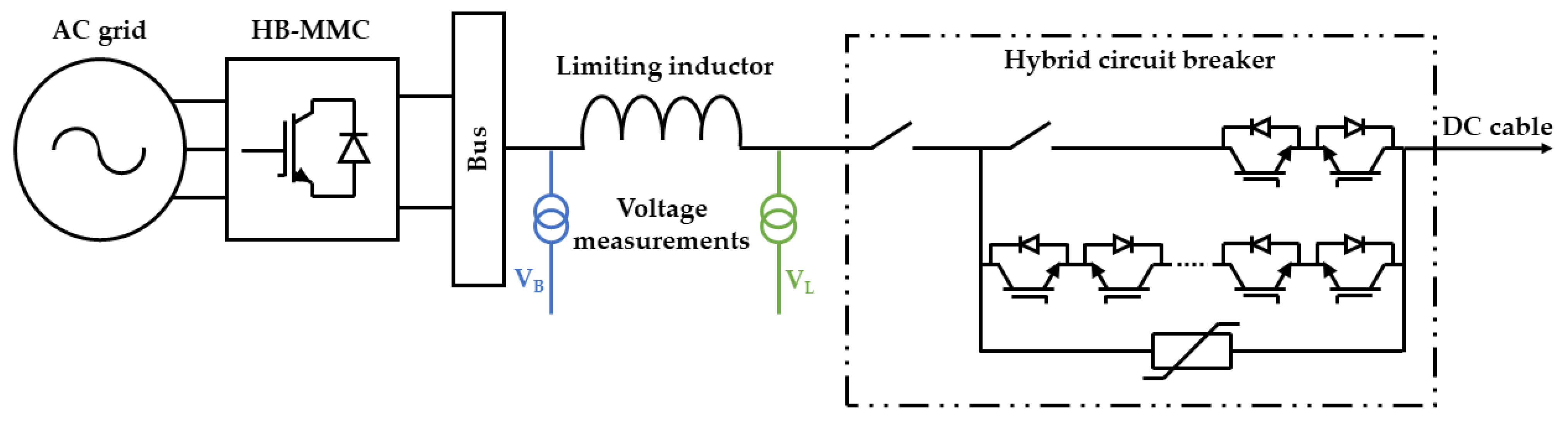
The proposed protection system exploits the characteristic damping effect of the limiting inductors, which delimit the protection zones. This way, voltage measurements are taken at both sides, as is shown in
Figure 1. The voltage measurements taken at the line side of the inductor, V
L, are used for the primary protection algorithm, while those taken at the bus side, V
B, are employed for the backup protection algorithm.
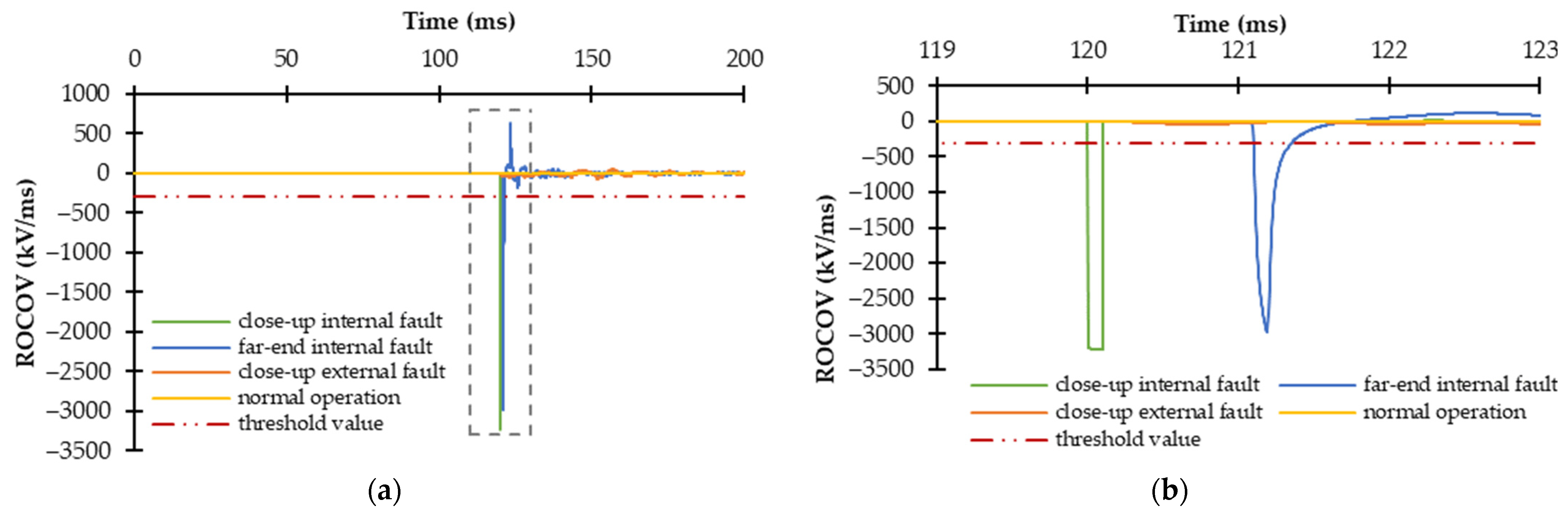
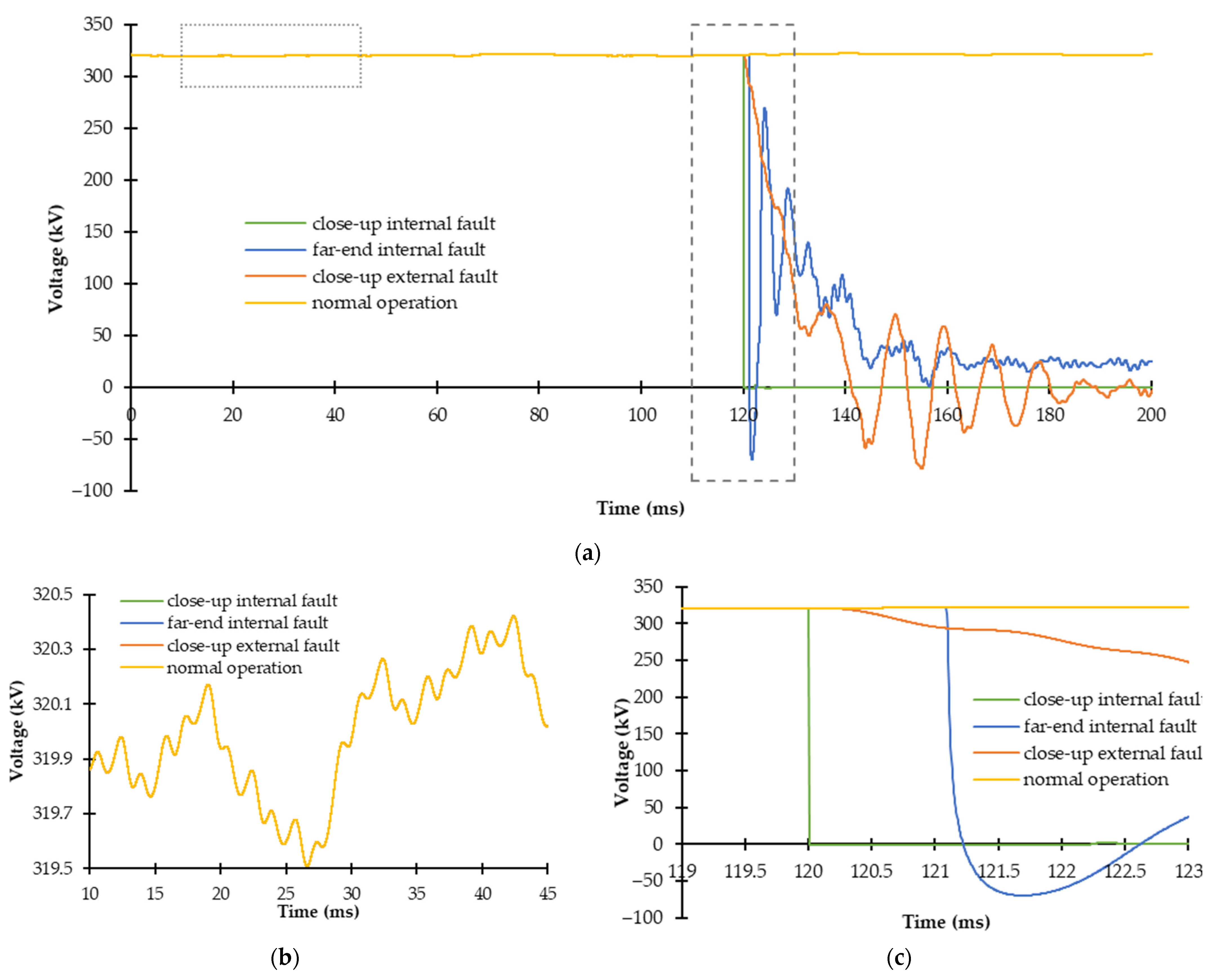
These measurements are processed and their derivatives are calculated. Therefore, both primary and backup protections are based on the Rate-Of-Change-Of-Voltage (ROCOV) algorithm. This fault detection method presents a very fast operation due to fault-induced collapse of the DC voltage, which can be seen in
Figure 2a,c. During normal conditions, the ROCOV value is close to zero while a sharp negative change is detected after fault inception, as is shown in
Figure 3.
This method is widely found in the literature since it presents higher sensitivity to high-resistance faults and faster fault detection than current-based algorithms, e.g., [
16,
17,
18,
19,
20,
21,
22]. Consequently, it has been selected for its application in this work as both primary and backup protections due to the restrictive speed requirement related to VSC-based systems, i.e., the fast rate of rise of the fault current and the low overcurrent withstand capability of the VSC’s components.
Therefore, the primary and backup protections employ V
L and V
B measurements, respectively, calculate their derivatives and then compare them with their respective threshold values THR
L and THR
B. The primary protection aims to detect all faults happening inside its protection zone, which, in this paper, refers to the cable where the relay is placed. This way, after fault inception (t
f), the calculated ROCOV
L falls under the pre-selected threshold value THR
L, as shown in Equation (1).
Figure 2 and
Figure 3 present different waveforms regarding the voltage and ROCOV values when different fault conditions happen at time 120 ms. Normal operation as well as the worst fault cases scenarios are presented, i.e., a close-up external fault that can be misdetected as an internal fault and a far-end internal fault that may not be detected if the primary algorithm is not sensitive enough. As it can be seen, during normal operation and close-up external fault conditions the ROCOV value is zero or a very low value in comparison with those measured when an internal fault happens. A threshold value is selected in order to discriminate between internal faults and external or normal operation conditions.
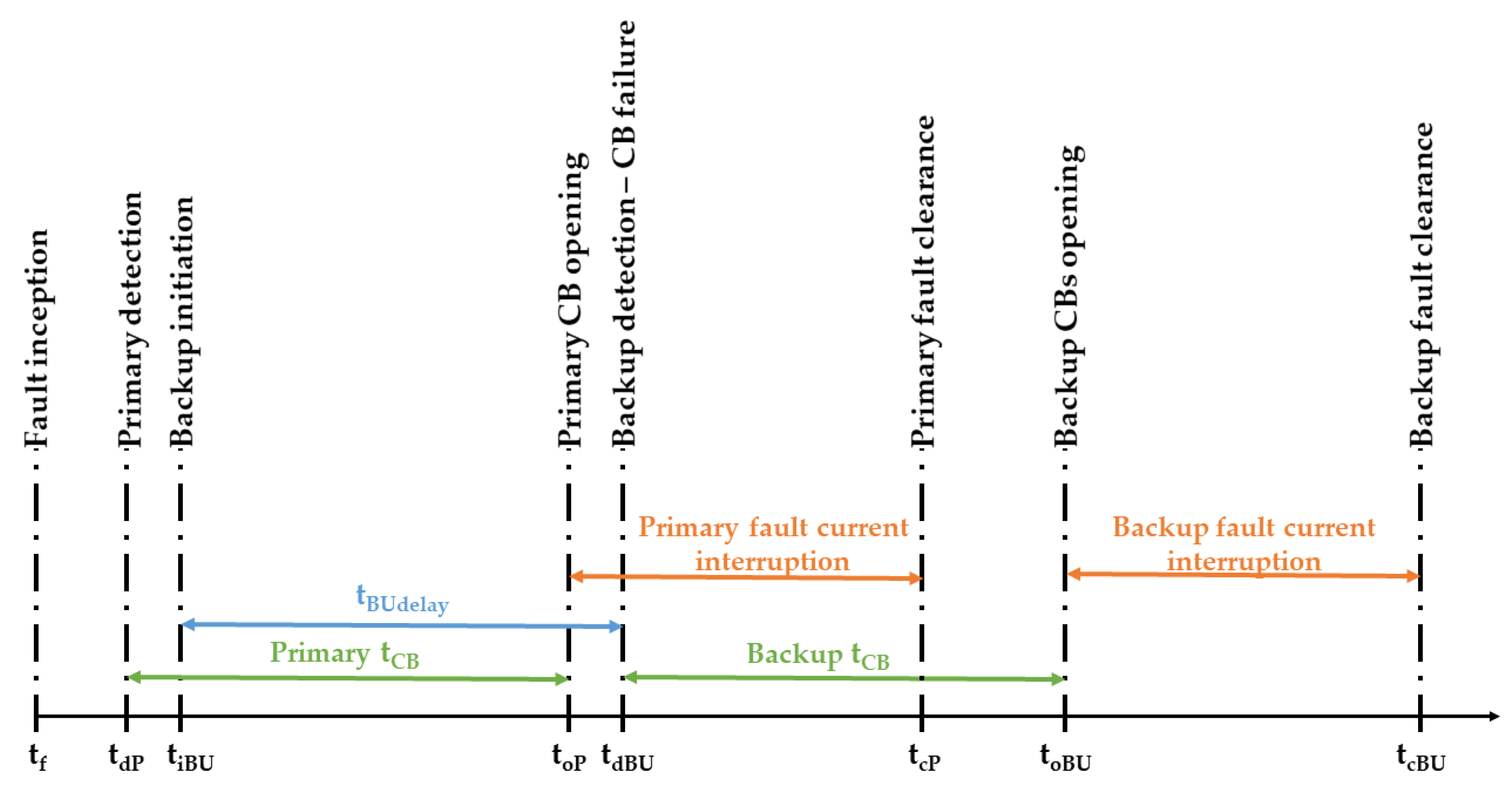
By that moment, fault detection by the primary protection algorithm is achieved (t
dP) and a tripping signal is sent to the corresponding circuit breaker. It operates (t
oP) and the fault is cleared (t
cP). The primary protection’s time steps are depicted in
Figure 4, as well as those corresponding to the backup protection that is explained hereunder.
On the other hand, the objective of the backup protection is to detect the failure to trip of a neighboring circuit breaker. Thus, the backup protection operates when fault detection is achieved on an adjacent link but the corresponding circuit breaker does not operate correctly due to a failure. All neighboring relays must detect the affected circuit breaker’s failure and trip their corresponding circuit breakers in order to properly clear the fault.
As previously mentioned, the requirement of operation speed is critical in VSC-based systems, as an excessive delay in tripping enlarges the consequences of the failure. Consequently, only local measurements are employed in order to make the backup protection as fast as possible and the ROCOV algorithm is selected since it presents one of the fastest fault detection capabilities among the local-measurement-based methods commonly employed in HVDC systems. However, the proposed backup protection scheme could be applied and adjusted to other primary algorithms as long as they are fast enough to detect DC faults while satisfying the restrictive speed requirement. The backup process is initiated (t
iBU) when a fault is detected on an adjacent link and the calculated ROCOV
B obtains a value lower than the threshold value THR
B, as shown in Equation (2).
Afterwards, the backup process is kept in standby for a time (tBUdelay) slightly greater than the operation time of the circuit breaker (tCB) so that the appropriate operation of the primary protection can be ensured before the backup protection’s operation.
Therefore, the presented work assumes that a failure has happened when the current has not been commutated to the energy absorbing branch of the circuit breaker after t
cb [
11]. After this time, the correct operation of the affected circuit breaker is checked. If it has operated, the backup process is terminated and the fault is cleared by the affected circuit breaker (t
cP). Otherwise, a circuit breaker failure is detected (t
dBU) and in consequence the corresponding neighboring circuit breakers operate (t
oBU) and the fault is cleared (t
cBU).
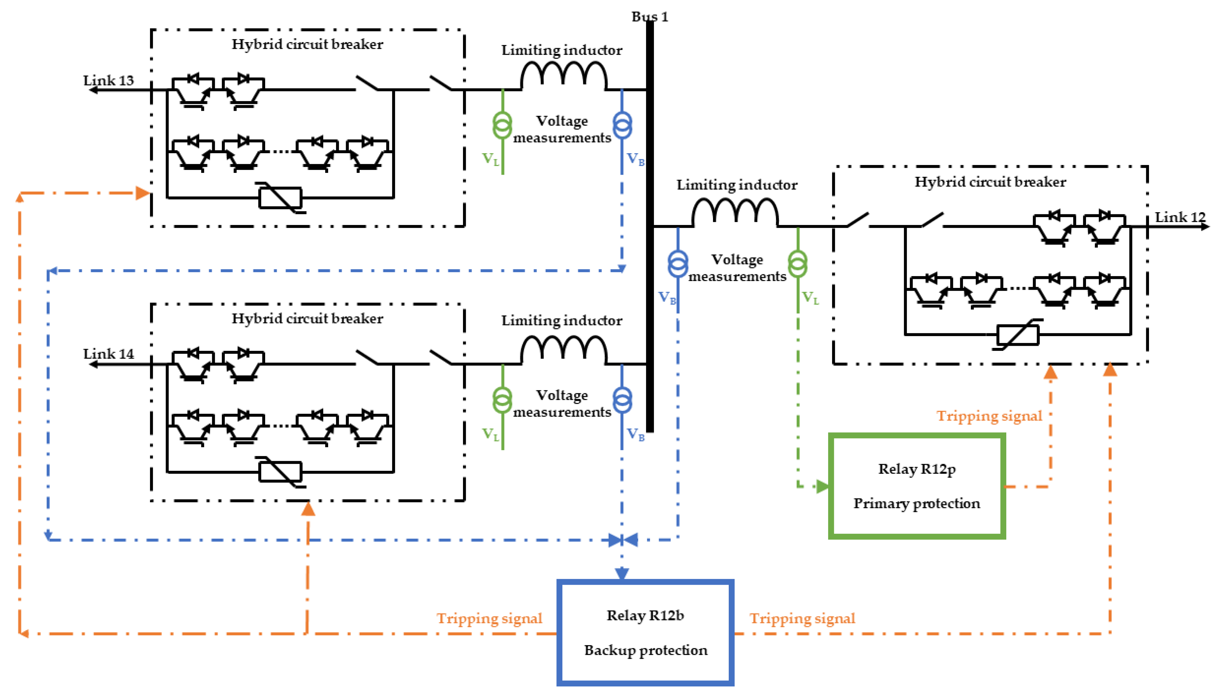
A diagram of the proposed protection scheme is represented in
Figure 5. This scheme only represents the positive poles of each link. The protection of negative poles operates the same way as the represented protection of positive poles. This diagram is related to Bus 1 and relay R12. It illustrates how the primary protection uses the voltage measurements (V
L) taken by R12p, then, the voltage derivative is calculated and compared with its corresponding threshold value, and if a fault is detected inside its protection zone, a tripping signal is sent to the circuit breaker placed in link 12. Meanwhile, the backup protection employs V
B measurements (R12b) from all neighboring links and calculates their derivatives. If a fault in the backward direction is detected and, after time t
BUdelay, the circuit breaker in link 12 has not operated, tripping signals to the circuit breakers located in links 13 and 14 are issued for backup operation.
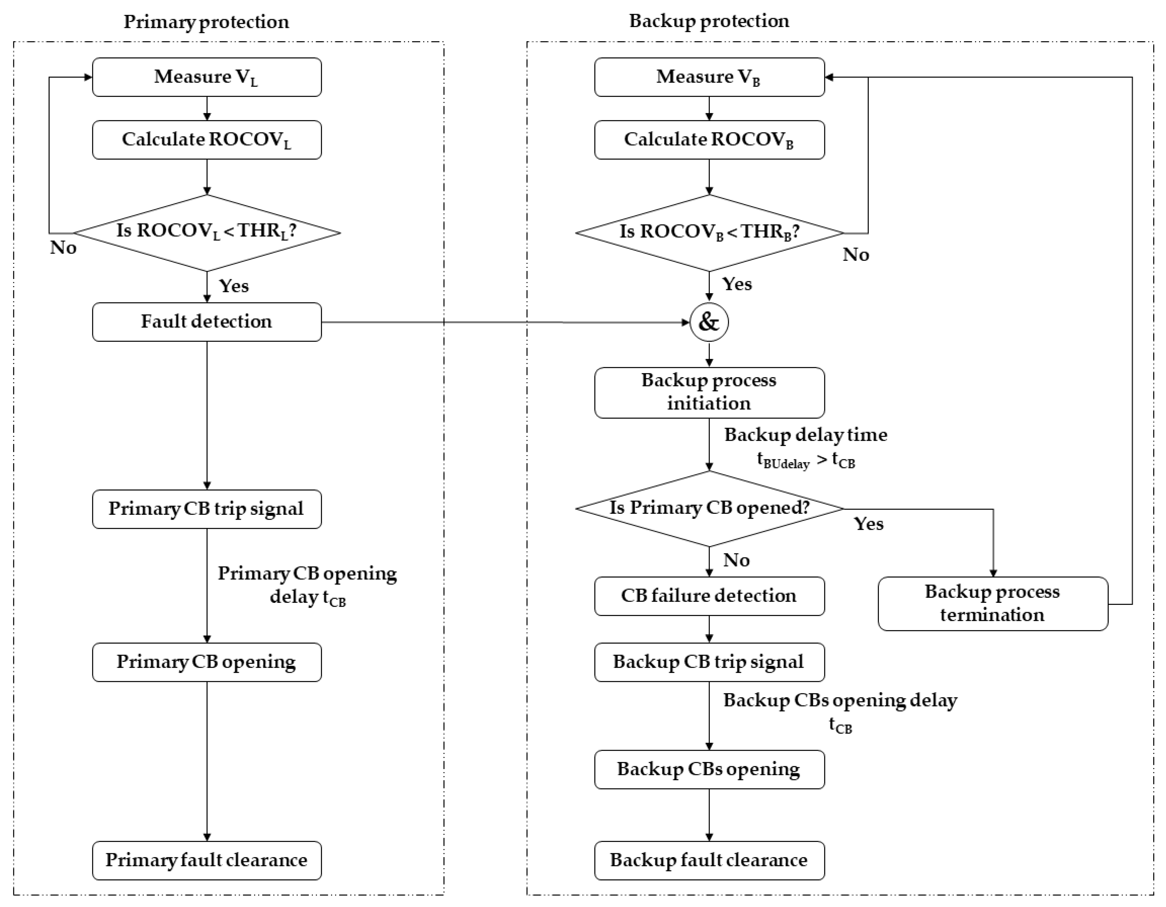
Additionally, the operation of the complete protection system proposed in this work is summarized in the flow chart shown in
Figure 6.
3. Study Case
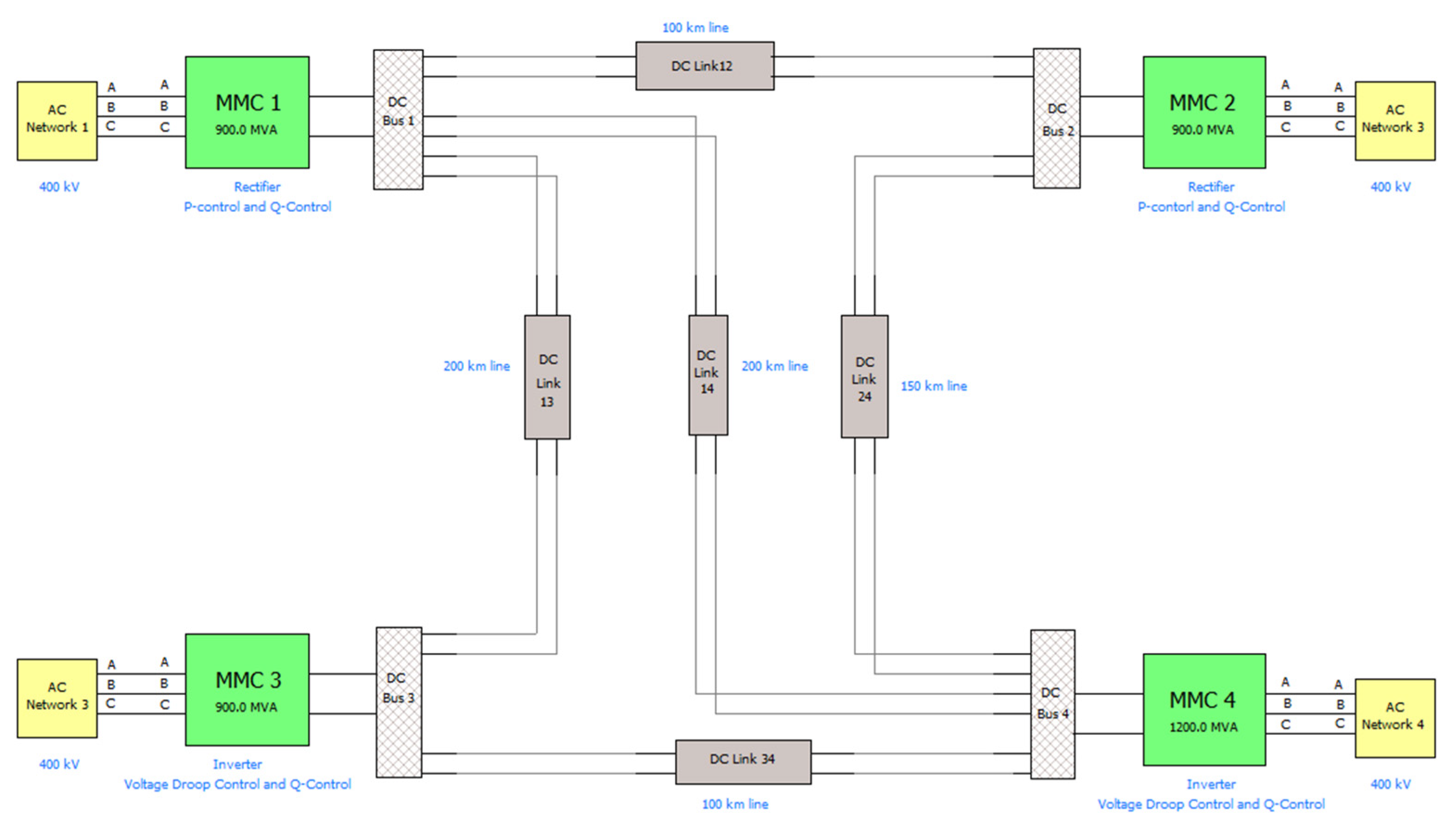
The proposed protection system is applied to a four-terminal HVDC grid modeled in PSCAD software and available in [
23]. The conversion topology employed is the Half-Bridge Modular Multilevel Converter (HB-MMC). The rated power of HB-MMC 4 is 1200 MVA, while the rated power of the three remaining converters is 900 MVA. The HB-MMCs are interconnected by five cables with 100 mH inductors and circuit breakers at their ends; this way, each cable comprises an independent protection zone. An inductor size of 100 mH is widely used in the literature when local-measurement-based algorithms are employed in order to accurately delimit the protection zones, e.g., [
14,
18,
19,
20,
23,
24,
25,
26,
27,
28].
Cables interconnecting converters HB-MMC 1 and 2 and HB-MMC 3 and 4 are 100 km long, those interconnecting HB-MMC 1 and 3 and HB-MMC 1 and 4 are 200 km long and the remaining one, which interconnects HB-MMC 2 and 4, is 150 km long. These cables are modeled by employing frequency dependent models [
23].
The operation time of the circuit breakers is assumed to be 2 ms in accordance with the hybrid circuit breakers found in the literature [
3,
29]. Cable lengths are shown in
Figure 7. Primary and backup protection algorithms are based on the principles stated in the preceding section. Therefore, for this HVDC system, threshold values for the primary and backup protections have been selected, i.e., THR
L and THR
B are −300 kV/ms and −5 kV/ms, respectively. These threshold values have been selected by employing a safety factor for improved selectivity and to avoid noise interference, as it can be seen in
Figure 3, where the threshold value depicted is THR
L and there is a considerably big difference between its value and the ROCOV value during normal operation or during a close-up external fault. Moreover, a sampling frequency of 10 kHz for ROCOV calculation and a time step of 5 μs for software simulation are employed.
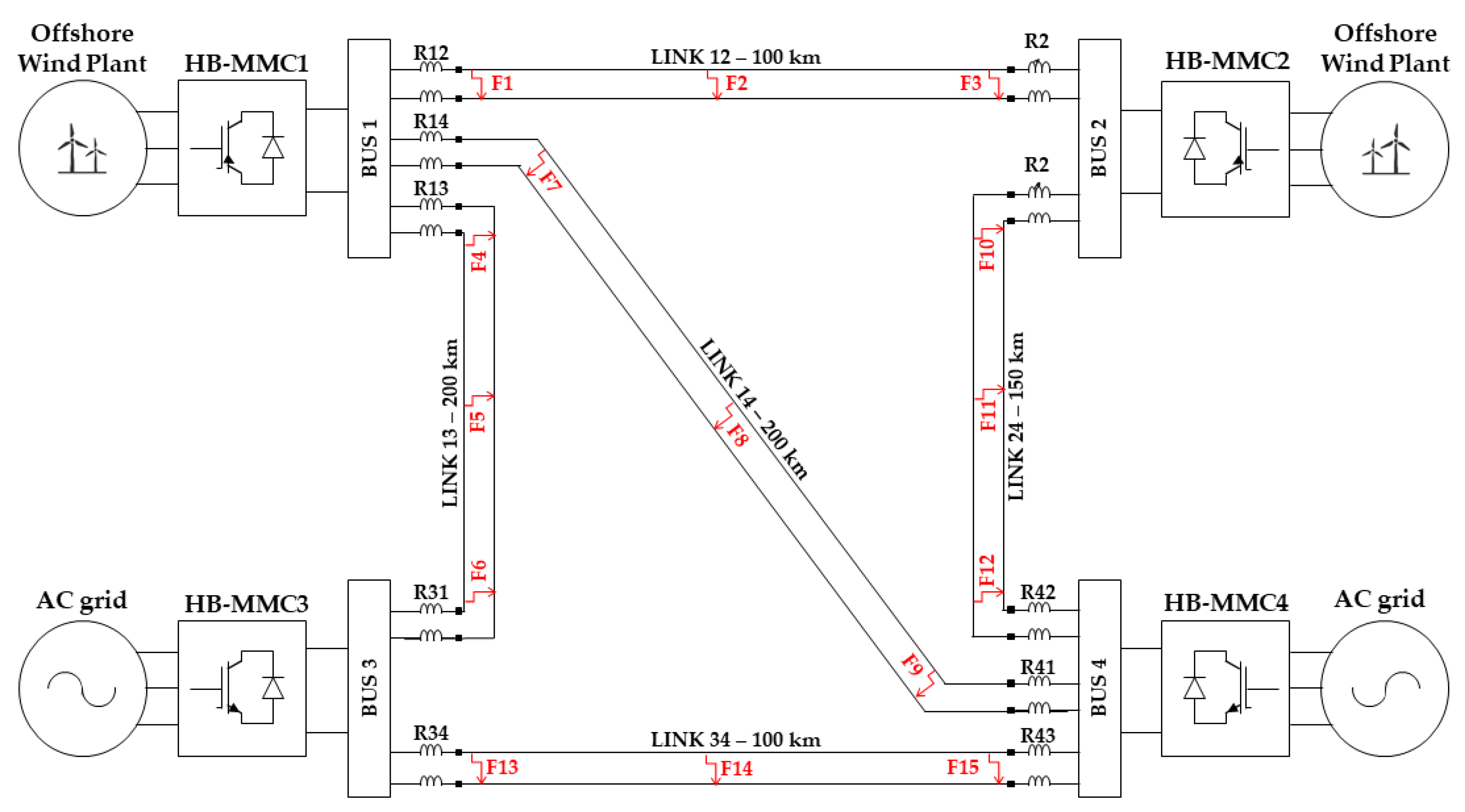
The proposed protection system is evaluated against different fault conditions. Hence, three fault locations are considered for each link, as shown in
Figure 8. Firstly, the protection system is tested against a range of Pole-to-Pole (PtP) faults. This way, the worst fault case scenarios are analyzed. A close-up fault presents the worst fault case scenario in terms of maximum current to be dealt with. Moreover, it can be misdetected as an internal fault by primary protection of the neighboring relays. Conversely, a fault located at the other end of the protection zone is the worst fault case scenario in terms of fault detection due to the attenuation effect. Additionally, faults at the midpoint of the link are considered as well. Afterwards, the correct performance of the protection system is demonstrated against Pole-to-Ground (PtG) faults and high-resistance fault case scenarios. Additionally, it is verified that no nuisance operation happens when there is no circuit breaker failure due to misdetection by the backup protection.
3.1. Pole-to-Pole Fault Conditions
A range of PtP faults are simulated in order to check the proper performance of the protection system. Fault locations are depicted in
Figure 8. Fault F2, F5, F8, F11 and F14 are located in the middle of the respective cables, while the remaining fault cases are placed at the ends of each cable, right in front of the corresponding relays. In addition, a circuit breaker’s failure condition is added to each simulated case as a way to evaluate the backup protection system.
Table 1 and
Table 2 summarize the results of this analysis and the fault detection times (in milliseconds) related to each relay.
Table 1 presents the circuit breakers that operate due to primary protection (symbol “P”), due to backup protection (symbol “BU”) and those who should have operated as a primary protection but have not due to a malfunction (symbol “F”). In addition, external relays to the affected protection zone that have not misdetected the simulated fault cases are represented with symbol “-“. Fault detection times regarding primary and backup protection are represented in
Table 2.
Taking fault case F1 as an example, this fault should be detected by the primary protection relays R12 and R21; however, the circuit breaker corresponding to R12 presents a failure meanwhile relay R21 detects the fault at 0.555 ms after fault inception. Therefore, the backup protection related to the neighboring relays of R12, i.e., R13 and R14, must detect the failure in order to properly clear fault F1. As is shown in
Table 1 and
Table 2, relays R13 and R14 are able to detect the failure of the circuit breaker related to R12 at 2.035 ms, which is a very fast detection since the operation time of the circuit breaker is assumed to be 2 ms. Fault clearance by R12 and R21 is achieved at 8.865 and 5.565 ms, while the maximum current handled by the circuit breakers is 7.53 and 4.92 kA. Furthermore, no other relays detect the fault condition, which demonstrates the correct performance of the protection system.
All simulated fault cases are properly detected and cleared by means of the proposed protection system.
3.2. Pole-to-Ground Fault Conditions
In this section, the proposed protection system is analyzed against different PtG faults. Fault locations are those depicted in
Figure 8 and the results of the simulations are summarized in
Table 3 and
Table 4.
In this case, when fault F1 happens, relay R12 is able to detect it in 0.005 ms while a failure occurs in the circuit breaker related to relay R21. Consequently, neighboring relay R24 detects the failure and sends a tripping signal to its corresponding circuit breaker in order to clear fault F1. Failure is quickly detected by R24 at 2.590 ms, taking into account that fault F1 is located at the other end of the protection zone. The fault clearance process ends at 4.755 and 6.110 ms for R12 and R21 with a maximum current interruption of 4.25 and 4.98 kA. Moreover, there is no nuisance operation by the remaining relays and all the simulated fault cases are correctly detected and cleared by the protection system.
3.3. High-Resistance Case Scenarios
High-resistance fault detection capability is also very relevant for the reliable operation of the system. Thus, the protection system must be tested against high-resistance faults.
First, a 200 Ω PtP fault located at link L14 at 60 km from R14 and 140 km from R41 is simulated. The circuit breaker associated with R14 presents a failure in this case. After fault inception, primary protections of relays R14 and R41 detect an internal fault in their protection zone after 0.335 and 0.785 ms and tripping signals are issued to their corresponding circuit breakers. Meanwhile, the backup protection of the neighboring relays associated with R14 and R41 is initiated at 0.405 and 0.860 ms, respectively. The corresponding circuit breaker to R41 operates at 2.790 ms; thus, the backup protections of relays R42 and R43 are terminated. Current interruption is achieved at 3.055 ms, while the maximum current was only 0.93 kA due the high-resistive feature and current polarity inversion from link–bus to bus–link. Meanwhile, the circuit breaker associated with R14 presents a failure; therefore, the backup protections of relays R12 and R13 detect the circuit breaker’s failure at 2.405 ms and issue their respective tripping signals. This way, the operation of the backup circuit breakers happens at 4.410 ms, clearing the high-resistive fault at 5.215 ms (maximum current of 2.535 kA).
Similarly, a 200 Ω PtG fault is simulated. It affects link L24 and it is located at 110 km from R24 and 40 km from R42. The circuit breaker associated with the latter relay malfunctions in this simulation case. Primary protections of relays R24 and R42 detect an internal fault at 0.650 and 0.235 ms after fault inception and issue the tripping signals. Backup protections of the neighboring relays initiate their process at 0.710 and 0.310 ms, respectively.
The circuit breaker related to R24 properly operates at 2.660 ms and the backup protection process of relay R21 is terminated. This circuit breaker has to interrupt a current of 1.51 kA and fault clearance is achieved at 3.140 ms from fault inception. Conversely, the circuit breaker associated with R42 malfunctions. This operation failure is detected by relays R41 and R43 at 2.315 ms; therefore, tripping signals are issued and circuit breakers’ operation is achieved at 4.320 ms, handling a current of 0.754 kA. Thus, the high-resistance fault is properly cleared at 4.550 ms. It must be highlighted that no remaining relay misoperates in both cases.
3.4. Non-Failure Case Scenario
In order to thoroughly check the performance of the backup protection, some fault cases are simulated where the primary protection clears the fault since there is no failure in its associated circuit breaker.
A solid PtP fault on link 34 located at 35 and 65 km from relays R34 and R43, respectively, is applied to the four-terminal grid. Fault detection is achieved at 0.195 and 0.360 ms by R34 and R43 after fault inception. Similarly, the backup protections of the adjacent relays initiate their processes at 0.220 and 0.395 ms, respectively. Then, their primary circuit breakers properly operate at 2.200 and 2.370 ms and the backup protection identifies their correct operation and terminates their processes. Currents of 4.50 and 5.53 kA are cleared at 5.330 and 6.425 ms, respectively, from fault inception.
On the other hand, the performance of the backup protection against a 200 Ω PtP fault when there is no failure in the circuit breakers is analyzed. The high-resistance fault is located on link 12 at 80 km from R12 and 20 km from R21. In this case, the fault detection time of the primary protection is 0.445 ms for R12 and 0.115 ms for R12. Likewise, the backup protection’s initiation time is 0.510 and 0.175 ms, respectively. Therefore, circuit breakers of R12 and R21 operate at 2.450 and 2.120 ms; thus, the backup protection’s process is terminated. The maximum current handled by the circuit breakers is 1.49 and 1.83 kA. Fault clearance is achieved at 2.940 and 2.875 ms, respectively.
No misdetection or improper operation occurred during these simulations.
4. Discussion
Backup protection must be able to quickly detect the failure in the clearance of a fault by an adjacent circuit breaker in order to fulfill the critical speed requirement. Moreover, a faster failure detection entails a lower maximum fault current that needs to be interrupted by the circuit breakers.
The reliable operation of the proposed backup protection has been demonstrated in
Section 3 for different fault conditions, varying the fault type, location and resistance. A circuit breaker’s failure can be quickly detected, just a few microseconds after its estimated operation time.
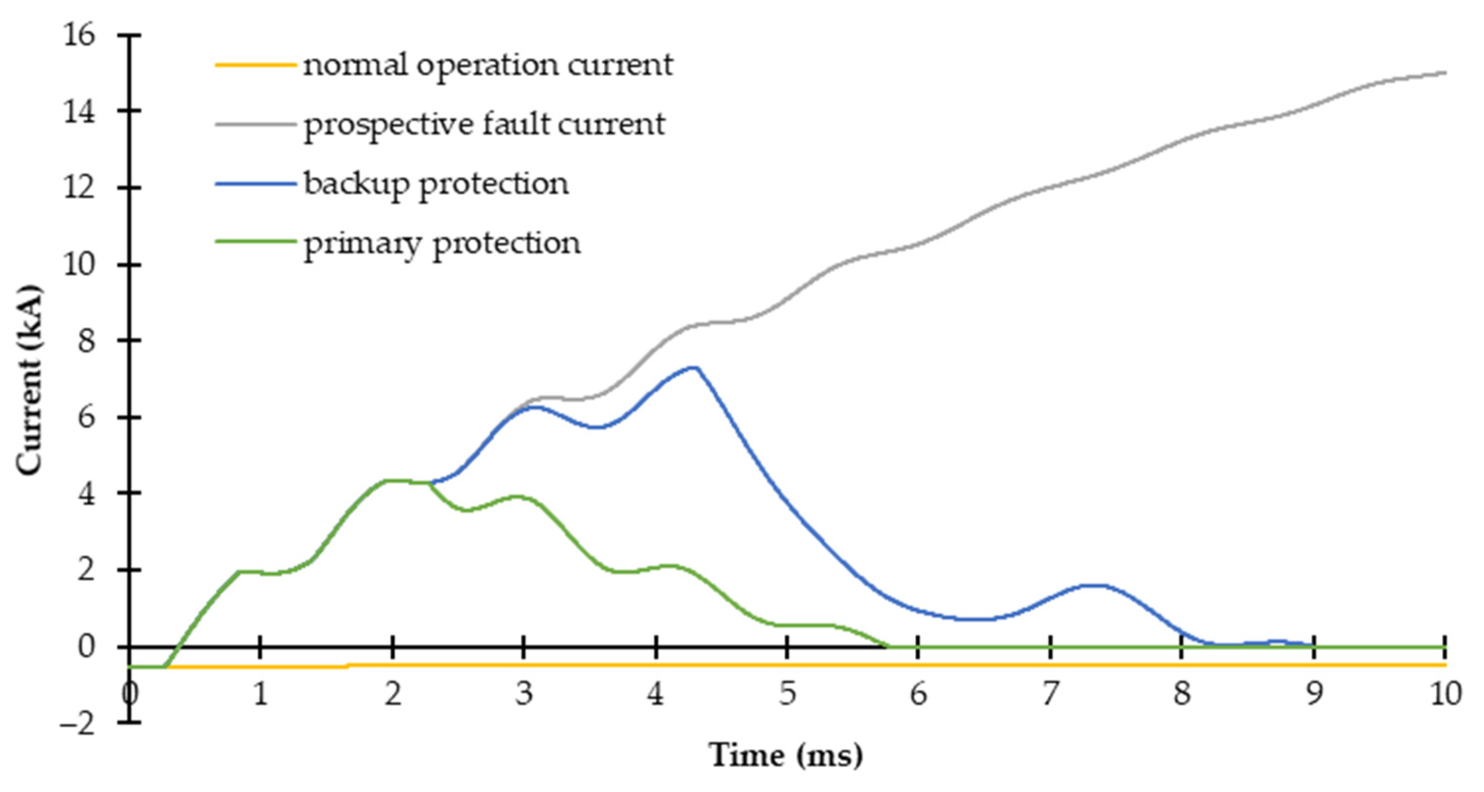
Figure 9 depicts the fault current waves regarding the operation of the primary and backup protection against a 0 Ω PtP fault located on link L14 at 150 km from relay R14 and 50 km from R41. The current waveforms regarding normal operation and the prospective fault current are also presented. It can be seen that fault clearance related to the backup protection starts around 4 ms after fault detection, which supposes a 2 ms delay regarding the start of the primary protection’s fault clearance process. This time delay of 2 ms is related to the time needed for a hybrid circuit breaker to commutate the fault current to the energy absorption branch, where the fault clearance process starts, after receiving the tripping signal.
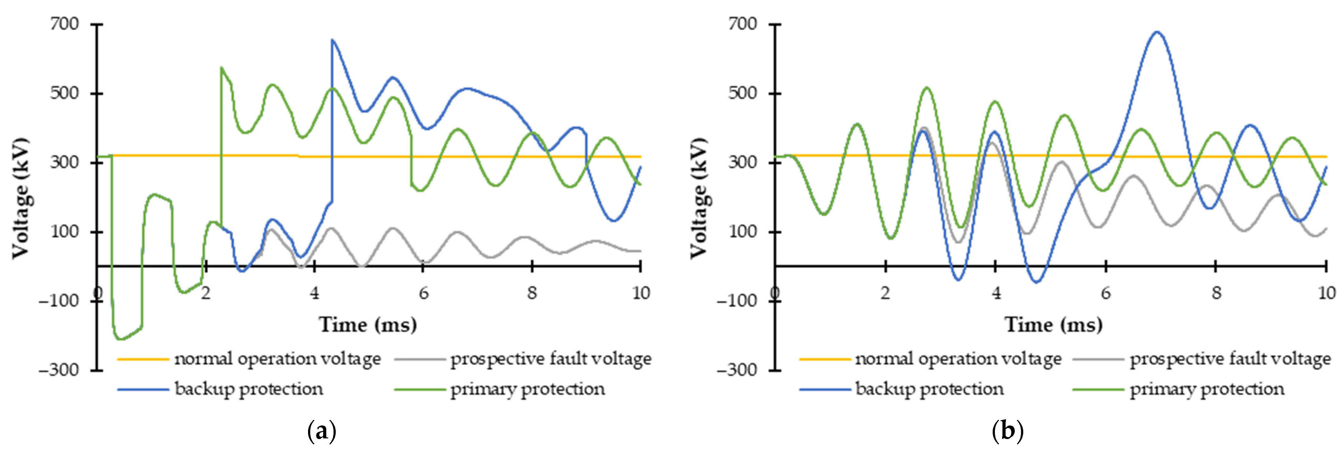
Figure 10 similarly shows the voltage waveform for both V
L and V
B for the same cases: normal operation, primary operation, backup operation and the prospective voltage related to a fault condition that has not been cleared.
As it can be seen in
Figure 9, fault clearance is achieved at approximately 6 ms and 8 ms for primary and backup protections, respectively. If a conventional backup protection had been used, failure detection would have been achieved after the estimated fault clearing time of the primary protection, i.e., approximately after 6 ms. By this time, the fault current would have risen up to 10 kA; however, the actual fault clearing process would have started after an additional 2 ms, i.e., around 8 ms after fault inception. By this time, the fault current would have reached very dangerous levels. However, the proposed backup protection finishes its fault clearance process at approximately 8 ms. Thus, the proposed backup protection is faster and avoids this problematic situation related to very high fault currents.
Figure 11 shows the fault detection and the failure detection times of the primary and backup protections for a PtP fault located at link 13, varying its position from relay R13 all along the link. The detection times are proportional to the fault location and the delay between them is slightly higher than 2 ms (the assumed operation time of a hybrid circuit breaker). Moreover, solid (solid line) and 200 Ω (discontinued line) fault cases are simulated and it is concluded that the effect of the fault resistance on the backup protection can be neglected.
Additionally,
Figure 12 presents the maximum fault currents dealt by the affected circuit breakers for the previously mentioned fault cases. The maximum fault current is higher when the backup protection operates due to the 2 ms delay, i.e., primary operation of the circuit breakers happens around 2 ms after fault inception, while backup operation takes place after 4 ms. The maximum fault current difference is in the range of less than 1 kA and 2 kA. The primary protection deals with a maximum of 6 kA, while the backup protection has to interrupt up to 8 kA.
5. Conclusions
There is a need for the identification of the potential failure modes of the operating HVDC circuit breakers, considering that the failure of a circuit breaker implies severe consequences for the HVDC grid. In this paper, a novel protection strategy that deals with the failure to trip of HVDC circuit breakers is presented. This novel backup strategy assists the malfunctioning of the primary protection, activating the neighboring circuit breakers. In consequence, the zone of backup protection overlaps each adjacent system element. It is able to detect the failure faster than the conventional backup protections, which have to wait after the estimated fault clearing time. This way, the fault current does not increase up to dangerous levels for the VSC-based system.
The proposed strategy is based on ROCOV algorithms for primary and backup protections, which are calculated at both ends of the limiting inductors that delimit each primary protection zone. Therefore, in case a circuit breaker fails to trip when requested, the adjacent circuit breakers operate as a way to clear the fault. Naturally, when the backup protection operates a larger part of the system is disconnected, compared with the primary protection appropriate operation.
The proposed strategy can be used with distinct primary protection algorithms and grid configurations. In the paper, it is validated in a four-terminal HVDC grid, considering three fault locations in each link. Close-up, remote and midlink locations are evaluated for PtP, PtG and high-resistance faults. All the considered case studies are properly detected and cleared without any nuisance operation. Additionally, it has been verified that when primary protections clear the faults, the backup protection process is interrupted. Therefore, it can be concluded that the proposed protection strategy is reliable, robust and remarkably fast.


