Article

Energy and Exergy Analyses of a Flat Plate Solar Collector Using Various Nanofluids: An Analytical Approach

1
School of Engineering and Technology, Central Queensland University, Rockhampton, QLD 4702, Australia
2
Clean Energy Academy, Central Queensland University, Rockhampton, QLD 4702, Australia
3
School of Engineering and Technology, Central Queensland University, Perth, WA 6000, Australia
*
Author to whom correspondence should be addressed.
Energies 2021, 14(14), 4305; https://doi.org/10.3390/en14144305
Submission received: 12 May 2021 / Revised: 1 July 2021 / Accepted: 13 July 2021 / Published: 16 July 2021

Abstract

:
Energy and exergy (EnE) efficiencies are considered the most important parameters to compare the performance of various thermal systems. In this paper, an analysis was carried out for EnE efficiencies of a flat plate solar collector (FPSC) using four different kinds of nanofluids as flowing mediums, namely, Al2O3/water, MgO/water, TiO2/water, and CuO/water, and compared with water as a flowing medium (traditional base fluid). The analysis considered nanofluids made of nanomaterials’ volume fractions of 1–4% with water. The volume flow rates of nanofluids and water were 1 to 4 L/min. The solar collector′s highest EnE efficiency values were obtained for CuO/water nanofluid among the four types of nanofluids mentioned above. The EnE efficiencies of the CuO nanofluid-operated solar collector were 38.21% and 34.06%, respectively, which is significantly higher than that of water-operated solar collectors. For the same volume flow rate, the mass flow rate was found to be 15.95% higher than water for the CuO nanofluid. The EnE efficiency of FPSC can also be increased by increasing the density and reducing the specific heat of the flowing medium.

1. Introduction

Nowadays, solar thermal collectors and photovoltaics are primary devices for collecting solar energy [1]. The solar thermal collector is a device to absorb heat from sunlight. It is designed in such a way that it helps to convert solar irradiation into more functional energy forms, such as hot water, molten salt, or applied to produce steam to generate electricity. Flat plate solar collector (FPSC) is considered as the better performing solar heater within other types of solar heaters. These FPSC are considered to have a fixed area for collecting the incoming radiation and are typically stationary throughout the day [2,3]. They are also considered to have a fixed area for collecting incoming radiation. The efficiency of these systems is explained as the extent to which the thermal energy impacts on the collector surface, and heat is transferred to the working fluid. Improved collector efficiency will be achieved by increasing solar absorption while reducing outgoing heat losses, a process known as energy transfer optimisation [4]. The collector′s efficiency can be improved by substituting the absorbing medium with high thermal conductivity (TC) fluids. The TC of a fluid can be increased by mixing a small quantity of nanoparticles with base fluid. For example, a 1 vol % of multi-wall carbon nanotube with base fluid could enhance TC by 40% [5].
The particle size of nanomaterials (nm range) is an important parameter. Although nanofluid increases heat transfer performance, large nanoparticles may cause instability of suspensions, flow resistance, clogging, and abrasion problems [6,7]. Nanofluids are colloidal suspensions of nanomaterials, including metals, metal oxides, non-metal, and oxides and carbon nanotubes in solutions or base fluids that are commonly employed as carrier fluids [8]. The nanofluids provide a larger surface area, higher thermal conductivity, better stability, and minimal clogging. In addition, nanoparticles are capable of changing the fluid characteristics [9].
The thermal performance of a FPSC can be significantly enhanced by employing an absorbing medium called nanofluids. Natarajan and Sathish [10] studied the impact of carbon nanotube (CNT) on the TC over the base fluid. They demonstrated that using these fluids as an agent medium in a standard solar water heater would improve performance. In a directive solar collector (DAC), Tyagi et al. [11] used aluminium nanoparticles with water as an absorbent medium. They reported that the DAC had 10% more efficiency than a standard flat plat solar collector [12]. Otanicar and Golden [13] studied the improvement of solar collector efficiency compared to a conventional collector under the environmental and economic influence and suggested some possible improvements. The effect of nanofluids on the performance of microthermal collectors has been experimentally studied by Otanicar et al. [14]. When the nanofluid is used as an absorbing medium, they observed an improvement in the efficiency of about 5% as compared to water.
Ziyadanogullari et al. [15] experimented with Al2O3/water and CuO/water to investigate the performance efficiency of FPSC. Their result showed CuO/water nanofluid achieved maximum efficiency compared to the other two nanofluids. The reason for these results may be because of differences in TC coefficients of the nanoparticles. Said et al. [16,17] experimentally and theoretically investigated the impact of utilising different sized Al2O3 nanoparticles (20 nm and 13 nm) suspended into a base fluid (water) on the EnE efficiencies of the FPSC. They performed their experiments with nanofluid of 0.3 vol % and 0.1 vol %, varying the mass flow rate from 0.5 to 1.8 kg/min. They reported that the nanoparticle size has an impact on the performance of FPSC. They found a 3% higher thermal performance enhancement when the size varies from 20 nm to 13 nm. Additionally, they recorded 83.5% theoretical thermal efficiency at 0.3 vol % and 1.8 kg/min of a mass flow rate. An overview of the literature analysis is presented in Table 1.
Table 1 provides an overview of FPSC performance improvement using metallic oxide nanofluid. It specifically indicates that the nanofluid was used in FPSC as heat transfer fluid, with a broad range of nanoparticles varying from 0.05 to 3 vol % and mass flow rate varying from 0.96 to 7.5 kg/min. It shows the optimum nanoparticle volume fraction (vol %) corresponding to FPSC maximum efficiency enhancement in nanofluid in the perspective of mass flow rate in laminar and turbulent flow conditions. Table 1 further indicates that employing Al2O3/water as a heat transfer fluid inside the FPSC improved the effectiveness of FPSC by 2–31.6% when nanoparticle concentrations of 0.1 to 3 wt.% and mass flow rates of 0.5 to 7.5 kg/min were maintained. In addition, Cu/water and CuO/water nanofluids improve the efficiency of 6.3 to 27.3% when the experiments were employed at a volume fraction that varies from 0.025 to 0.5 vol % and the mass flow rate changes from 1 to 8.8 kg/min, when compared to traditional fluids.
The energy equation alone is insufficient to determine the efficiency of a FPSC in thermodynamics analysis. The second law, also known as exergy analysis, is more successful in determining the source and amount of irreversibility and may be utilised to soptimise system efficiency. Exergy is the maximum output that may be obtained in relation to the difference in temperature [29]. Saidur et al. [30] performed an exergy study on a variety of solar energy applications and FPSCs’ [31]. Alim et al. [32], and Zhong et al. [33] conducted a thorough study of entropy generation in a FPSC utilising various metal oxide nanofluids. Most of the published research [34,35,36,37] focus on the thermal performance of FPSC utilising different working fluids at a constant flow rate which has a limited application in reality. Therefore, a more detailed and accurate study of their performance requires more and more up-to-date research. The aim of our paper is to analyse the EnE efficiency of a FPSCs’ using the different absorbing medium as nanofluids. Furthermore, the effect of mass flow rate, volume fraction, specific heat, density, and outlet temperature on EnE efficiency for a given operating condition are investigated. The effect of fraction factor and pumping power in variable flow rate can be evaluated in this study. A previous study was done for a single/given particle, whereas, for variable flow rate, we can determine which particle is performing better compared to many others. The nanofluids made of Al2O3, MgO, TiO2, and CuO nanoparticles in water were considered in this study. The first law of thermodynamics was used to calculate energy efficiency, while the second law of thermodynamics was used to determine exergy efficiency.

2. Analytical Approach

2.1. The First Law of Thermodynamics for Energy Efficiency

The first law of thermodynamics states that the energy is conserved, and the overall amount of conserved energy remains constant. However, different types of energies (such as potential, kinetic, and internal) can be changed from one form to another. An energy balance can be expressed using the law as follows [38]:
Q ˙ P = o u t l e t m ˙ k ( h + g z + w 2 2 ) k i n l e t m ˙ k ( h + g z + w 2 2 ) k
The absorbing mediums’ potential heat gain (Qu) may be expressed as,
Q u = m ˙ C p ( T f , o u t T f , i n )
The following formulas determine the heat capacity and density of nanofluid. [39,40]
C p , n f = ϕ C p , n p + C p , b f ( 1 ϕ )
ρ n f = ( 1 ϕ ) ρ b f + ϕ ρ n p
The Hottel–Whillier Equation is another equation for calculating the potential heat gain rate Q ˙ u of a FPSC. The Equation that accounts for heat losses between the solar collector and atmosphere as follows [41].
Q ˙ u = A p F R [ S U 1 ( T f , i n T a ) ]
The amount of absorbed irradiation per unit area of solar collector absorber plate (S) is calculated as follows,
S = I T ( τ α )
where (τα) is an optical efficiency (ηo) [42].
FR can be defined by,
F R = m ˙ C p U 1 A p [ 1 exp { F U 1 A p m ˙ C p } ]
An energy balance equation of the absorber plate in the rating form can be expressed for a steady-state condition as [42],
Q ˙ u = A p S U 1 A p ( T c T a )
In this study, the absorber plate′s average temperature, absorbed irradiation flux per unit area, overall loss, and absorber plates’ area were all considered to remain constant. The instantaneous collector efficiency is calculated by Equation (9) or Equation (10).
η E n = Q ˙ u A p I T = m ˙ C p ( T f , o u t T f , i n ) I T
η E n = F R ( τ α ) F R U 1 T f , i n T a I T
The current study was conducted under the usual incidence condition; FR(τα), FR, and U1 were constant at the tested temperatures [5]. However, it should be remembered that different types of energy have additional chances of generating work. As a result, efficiency specification was limited to a comparison of quantities that were metrically equivalent but not conceptually equivalent.

2.2. The Second Law of Thermodynamics for Exergy Efficiency

Energy efficiency is not enough to describe a thermodynamic process because the energy equation does not encounter internal losses. The second law of thermodynamics provides more information about the optimal operating stage, inefficiencies, corresponding magnitudes and traces [31,43]. It assumes that actual processes are not reversible and that the processes accumulate entropy. Molecular diffusion, friction, and hysteresis are examples of typical irreversible processes. The second law, according to the Clausius argument, can be written as [38]
o u t l e t ( m ˙ . s ) k i n l e t ( m ˙ . s ) k = j ( Q ˙ T ) j + σ
The irreversibility is not considered in the analysis of the first law of thermodynamics. On the other hand, the second law addresses irreversibility without using the word work. The first and second laws are merged to gather further details. The Gouy–Stodola equation [44] can be obtained by combining Equations (1) and (11).
P = n Q ˙ n ( 1 T a T n ) + I n l e t m ˙ k ( h T a s + w 2 2 + g z ) k O u t l e t m ˙ k ( h T a s + w 2 2 + g z ) k T a σ
Exergy is described as the work that is obstructed to its dead state. When the environment and the system are in balance, there is no more work to be done. The process is said to be in a dead state at this stage. So, the Equation (12) can be rewritten in terms of exergy for a control volume as shown below:
( E ˙ P ) o u t ( E ˙ P ) i n = ( E ˙ Q ) i n ( E ˙ Q ) o u t + ( E ˙ m ) i n ( E ˙ m ) o u t σ T a ( E ˙ P + E ˙ Q + E ˙ m ˙ ) i n = ( E ˙ P + E ˙ Q + E ˙ m ˙ ) o u t + σ T a
Therefore,
σ T a = i n E ˙ j o u t E ˙ k
where the exergy of work E ˙ p , the exergy of heat Q ˙ at a temperature of T, the exergy E ˙ Q exergy of a mass flow E ˙ m ˙ can be defined as follows:
E ˙ P = P E ˙ Q = Q ˙ ( 1 T a T ) a n d E ˙ m ˙ = m ˙ [ ( h h o ) T a ( s s o ) + w 2 w o 2 2 + g ( z z o ) ]
The difference in measured exergy at the inlet and outlet of the control volume will then be used to quantify irreversibility. In steady state, the exergy balance per unit area of the solar collector is given by [45]:
E ˙ g = η o E ˙ s u n E ˙ l o s s
The loss of exergy because the pressure drop of the fluid is assumed to be negligible. Alternatively, Equation (14) can also be represented as [46],
  E ˙ i n   E ˙ o u t =   E ˙ d e s t
In steady state, the exergy collection rate is the amount of energy gained by the heat transfer fluid as the temperature of the fluid rises from Tf in at the inlet to Tf out at the outlet. The exergy collection rate can be expressed without considering the mechanical exergy if the fluid is incompressible by using the following Equation:
E ˙ g = m ˙ C p ( T f , o u t T f , i n T a ln T f , o u t T f , i n )
When considering the usable exergy ratio for solar radiation, two crucial points should be kept in mind. On earth, the radiating solar flux can always be assumed to be a steady state condition but not in an equilibrium condition. The other is that the Sun′s radiation is an open system, which implies it is not possible to recover photons, as opposed to the equilibrium system. Carnot of (1 − Ta/Ts) is deemed appropriate from these facts for exergy with the solar radiation, which has the same form as the result of Jeter [47]. The exergy flow from the sun can be defined from the above information as:
E ˙ s u n = I T ( 1 T a T s )
The absorber plate is absorbed solar radiation from the sun, , and to heat is then transferred to working fluid. As shown in Figure 1, exergy destruction occurs during these two processes, including the flowing sections, as illustrated [45].
Absorption exergy loss (radiation plate): when solar light at Ts is absorbed by the absorber at Tc, an exergy annihilation event occurs.
Leakage exergy loss (plate ambient): a process of exergy loss followed by heat leaking from the absorber into its environs.
Conduction exergy loss (plate fluid): heat conduction between the absorber and the heat transfer fluid causes exergy annihilation.
Through Gouy-theorem Stodola′s [48], the aforementioned three types of exergy loss processes are strongly connected to the entropy generating rates. The following thermodynamical concepts may be used to derive these three entropy production rates:
Δ s ˙ r p = 0 1 k I T ( 1 T 1 1 T s ) d σ
Δ s ˙ p a = 0 1 U 1 ( T 1 T a ) ( 1 T a 1 T 1 ) d σ ,   a n d
Δ s ˙ p f = 0 1 k ( T 1 T f ) ( 1 T f 1 T 1 ) d σ
Even though Equations (18)–(20) cannot be integrated without knowing local absorber temperature (T1) and the heat transfer coefficient distribution; these equations may be approximated using the mean absorber temperature as shown below:
Δ s ˙ r p = k I T ( 1 T c 1 T s )
Δ s ˙ p a = U 1 ( T c T a ) ( 1 T a 1 T c ) ,   a n d
Δ s ˙ p f = T f , i n T f , o u t m ˙ C p d T T m ˙ C p ( T f , o u t T f , i n ) T f , o u t
The first right term in Equation (23) is an entropy flow from the absorber fluid, and the second one is an entropy of energy gathered from the absorber. The difference between the two variables becomes the entropy production rate while the heat is transferred from the absorber into the fluid. The phrase of exergy loss Equation (14) can be seen from Equations (21)–(23) using the Gouy-Stodola′s theorem as,
E ˙ l o s s = T a ( Δ s ˙ r p + Δ s ˙ p a + Δ s ˙ p f )
As a result, the steady-state exergy-balance-equation of a solar collector may be obtained by inserting Equations (16), (17), and (24) into Equation (14). After a few modifications, it becomes:
m ˙ C p ( T f , o u t T f , i n T a ln T f , o u t T f , i n ) = I T ( 1 T a T s ) [ ( 1 η o ) I T ( 1 T a T c ) + I T T a ( 1 T c 1 T s ) + U 1 ( T c T a ) ( 1 T a T c ) + m ˙ C p T a ( ln T f , o u t T f , i n T f , o u t T f , i n T c ) ]
The energy balance of a solar collector can be derived by rearranging Equation (25) as follows
m ˙ C p ( T f , o u t T f , i n ) = η o I T U 1 ( T c T a )
From Equation (25), the exergetic efficiency can be expressed by Equation (27) as follows:
η E x = E ˙ g E ˙ s u n = 1 [ ( 1 η o ) 1 T a / T c 1 T a / T s + 1 / T c 1 / T s 1 / T a 1 / T s + U l ( T c T a ) I T 1 T a / T c 1 T a / T s + m ˙ C p T a I T ( 1 T a / T s ) ( ln T f , o u t T f , i n T f , o u t T f , i n T c ) ]
= 1 [ e o p t + e r p + e p a + e p f ]
In Equations (27) and (28), the words in brackets indicate loss of exergy and have the following physical significance:
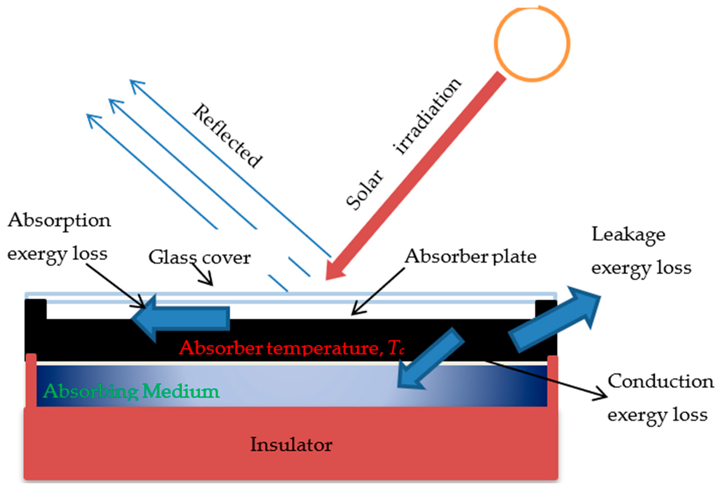
eopt: Optical loss percent solar energy absorbed owing to glazing transmissiveness and amorphous absorption.
erp: When solar radiation at Ts is absorbed by the absorber at Tc, there is a loss fraction. (Absorption at low temperatures degrades the high-quality energy).
epa: A portion of the exergy lost by the absorber to the environment.
epf: The heat transfer from the absorber to the fluid is accompanied by a heat-conduction loss percentage.
The terms (1 η=) and Ul (Tc − Ta)/IT in the well-known formulation of energy efficiency correspond to two of the aforementioned loss fractions, eopt and epa; it is worth mentioning that the word epf is quite close to the collector efficiency factor, which stands for loss of heat conduction. The following link is discovered using the temperature distribution correlations in the collector [45]:
T f , o u t T a S / U 1 T f , i n T a S / U 1 = exp ( U 1 A p F m ˙ C p )
In order to remove the component of output fluid temperature from Equation (27), the collector exergy efficiency correlation is recast as follows [49]:
η E x = m ˙ C p [ ( T f , i n T a S U 1 ) ( exp ( U 1 A p F m ˙ C p ) 1 ) ] m ˙ C p [ T a ( exp ( U 1 A p F m ˙ C p ) 1 T f , i n ( T f , i n T a S U 1 ) + 1 ) ] A p I T [ 1 ( T a T s ) ]

3. Input Data and Methodology

3.1. Input Data

Some assumptions were made to simplify the analysis in this study. Other heat transfer coefficients were assumed to be constant, such as the absorbing fluid characteristics, exergy flow rate, Solar flux, total heat loss, and heat transfer coefficients. Furthermore, the temperature of the fluid entering the system and the temperature of the surrounding environment were both considered to be constant and equal. Table 2, Table 3 and Table 4 include information on the characteristics of nanoparticles, the solar collectors’ parameter, and the analytic condition, respectively.

3.2. Methodology

The excel equation solver was used to extract the results. The input parameters from Table 2, Table 3 and Table 4 and, the Equations from 1–30 have been used to obtain analytical results. The Equations (3) and (4) have been used to estimate the specific heat, and density of a given nanofluids. The Equations (9), (10), and (30) have been used to calculate the EnE analysis of this analysis.

4. Results and Discussions
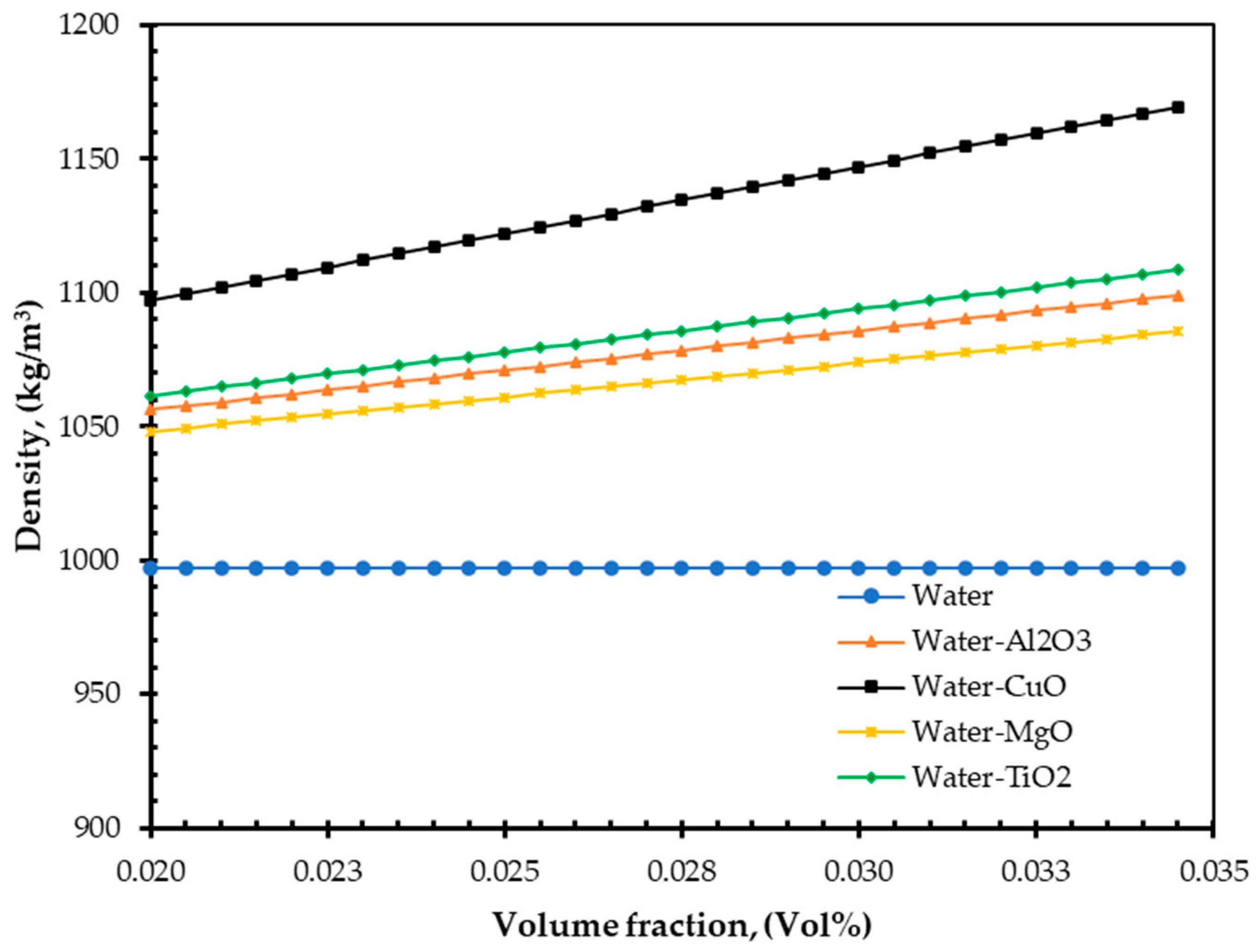
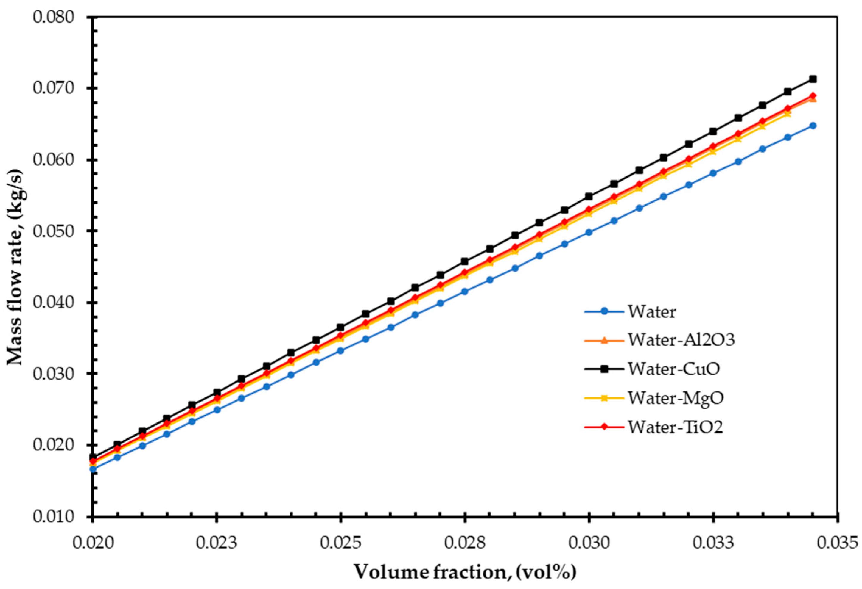
The chosen environmental and analytical conditions of the solar collector and constant parameters for the analytical approach are shown in Table 5. Collector efficiency was calculated using Equations (9), (10), and (30) and Table 2, Table 3 and Table 4. The EnE efficiency values are presented in Table 5.
The maximum enhancement results of EnE analysis are represented in Table 5. It is showed that the highest level of EnE enhancement was found for CuO/water nanofluids. The results are similar to available literature [32]. Energetic and exergetic efficiencies of different nanofluids such as SiO2/water, TiO2/water, Al2O3/water, CuO/water, and Gr/water, were experimentally investigated by Verma et al. [53]. They found the CuO/water nanofluids achieved maximum efficiencies. A group of nanofluids (SiO2/water, TiO2/water, Al2O3/water, GNP/water, and SWCNT/water) were also examined and compared their efiiciencied by Elcioglu et al. [54]. Additionally, they verified that, the increase in volume fraction of nanofluids enhanced the absorber’s efficiency for all nanofluids investigated.
Investigating the outputs of Luminosu et al. [43] for the solar collector′s open circuit mode and the computer simulation of the solar collector developed by Farahat et al. [31] enables the verification of the findings acquired through the analytic approach. Table 6 compares the analysed exergy efficiency with an experimental work [43], and analytical analysis [32] and the computer simulation [31] performed in Iran.
These findings are in excellent accordance with the literature data of Reference [32]. Our results vary only about 9% with Reference [32], which is well acceptable. The deviation was higher for the others two data of references [31,43] due to their numerical and experimental parameters were different compared to the present analysis. For example, the solar radiation and the temperature difference are different from our analysis. It was realised that the solar radiation and ambient temperature had an impact on the exergy efficiency, particularly at the high flow rates [21]. The results are also in good agreement with the recently published experimental study [55]. They reported the maximum exergy enhancement was about 3.33% which is very close to this study (3.35%) analysis. The following observations can be noted.
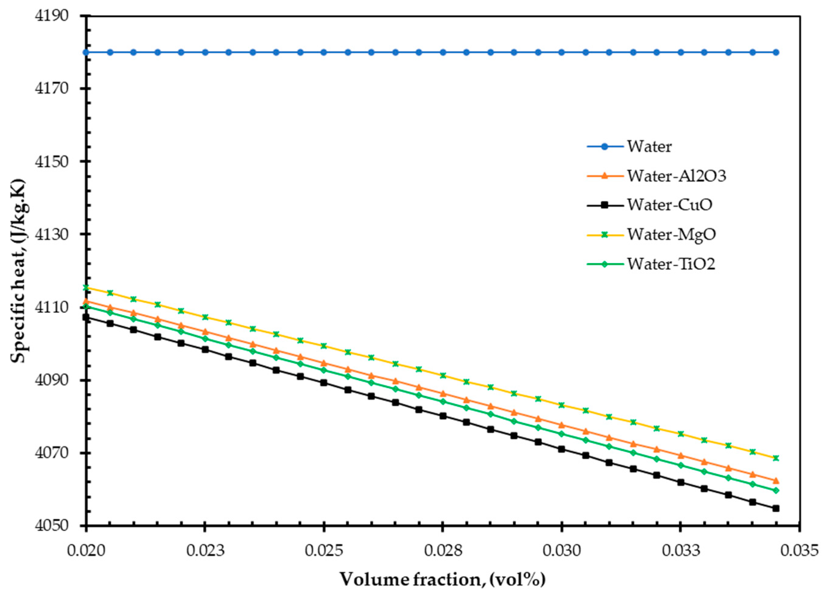
As nanofluids replace water as an absorbing medium, the nanofluids’ viscosity, density, and TC increase, but its specific heat decreases compared to the base fluid (water). Interestingly, these findings are in agreement with those of Pandey et al. [50].
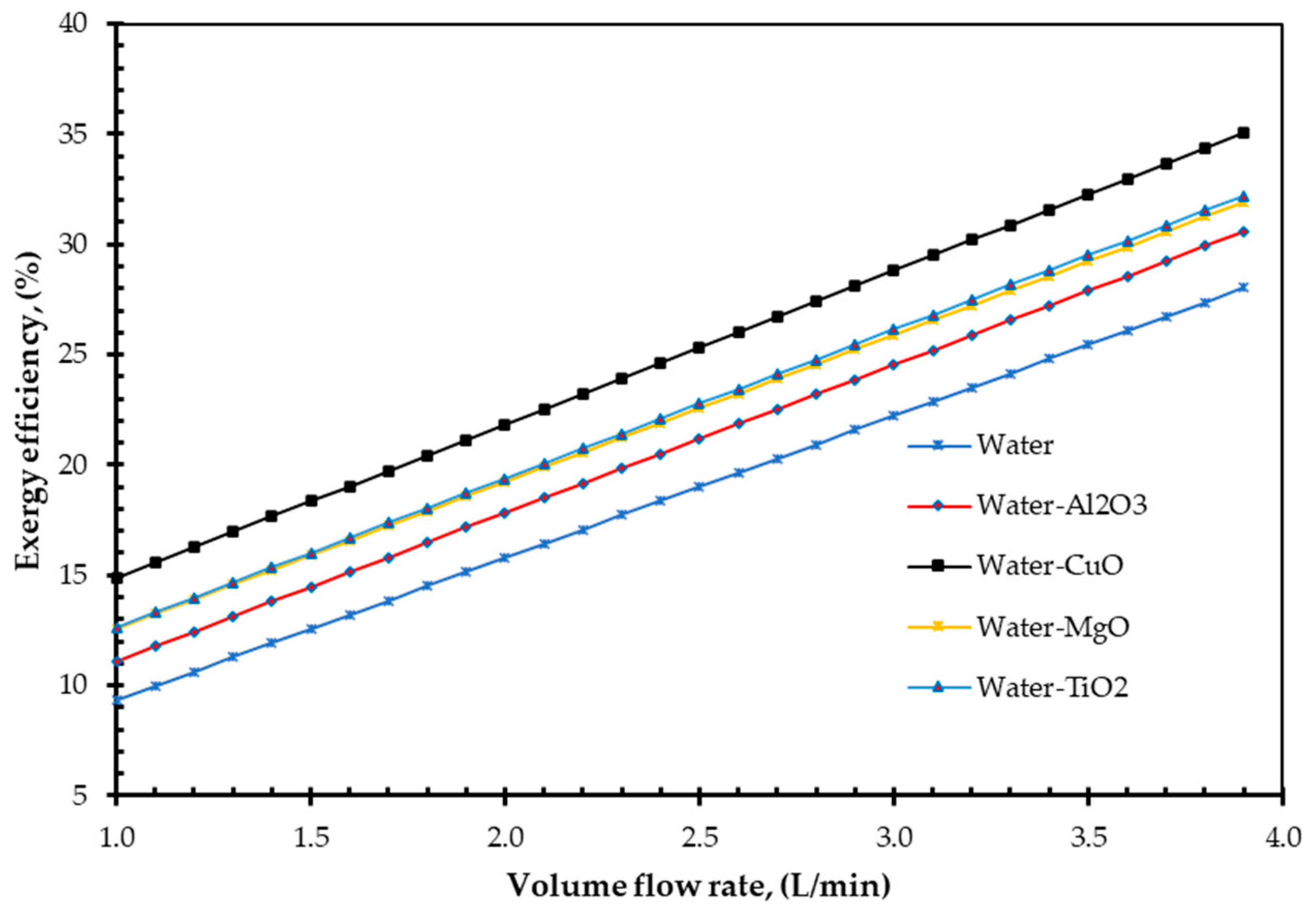
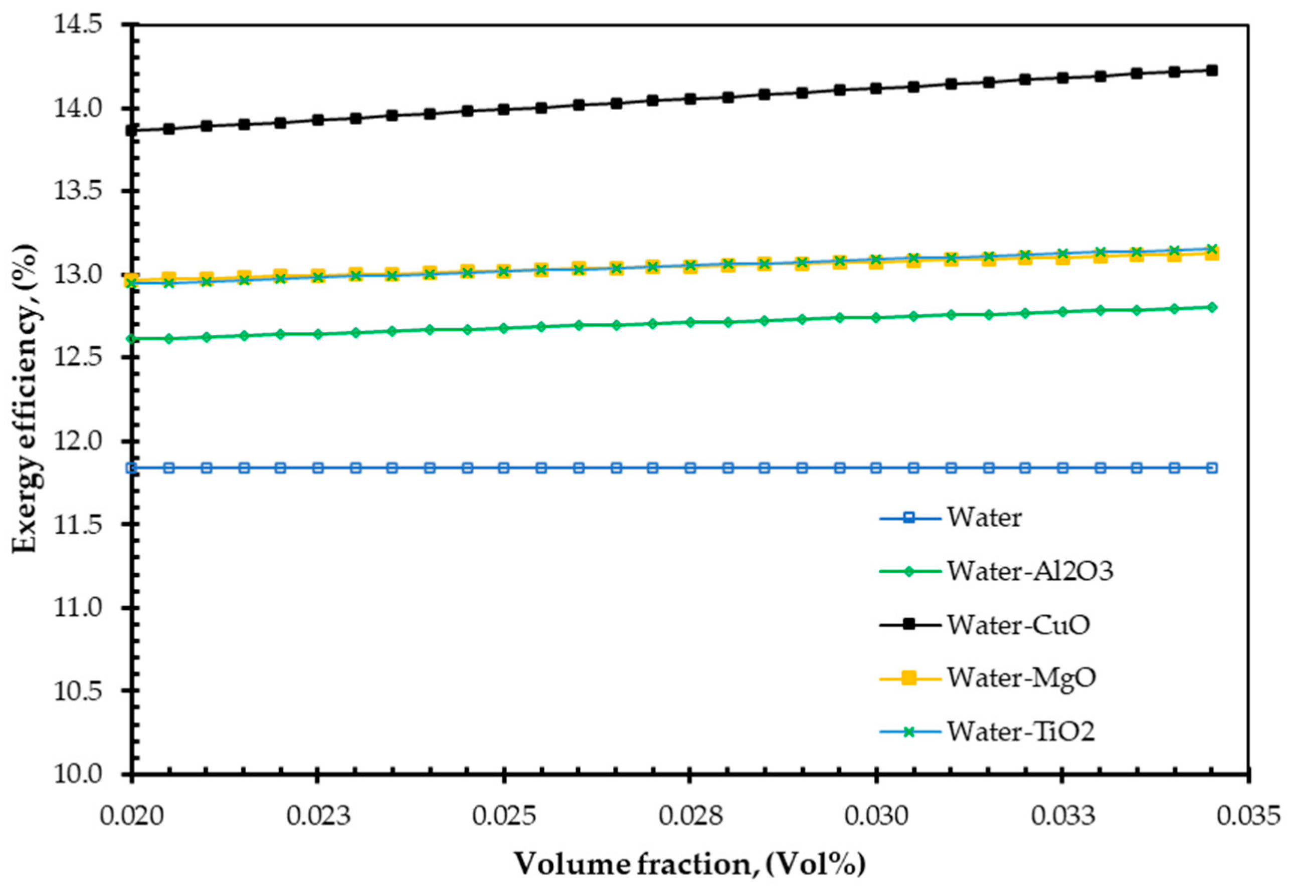
To gain exergy, the entropy generation number is typically expected to decrease. The entropy generation number decreases when nanofluids are used as agent fluids [51].
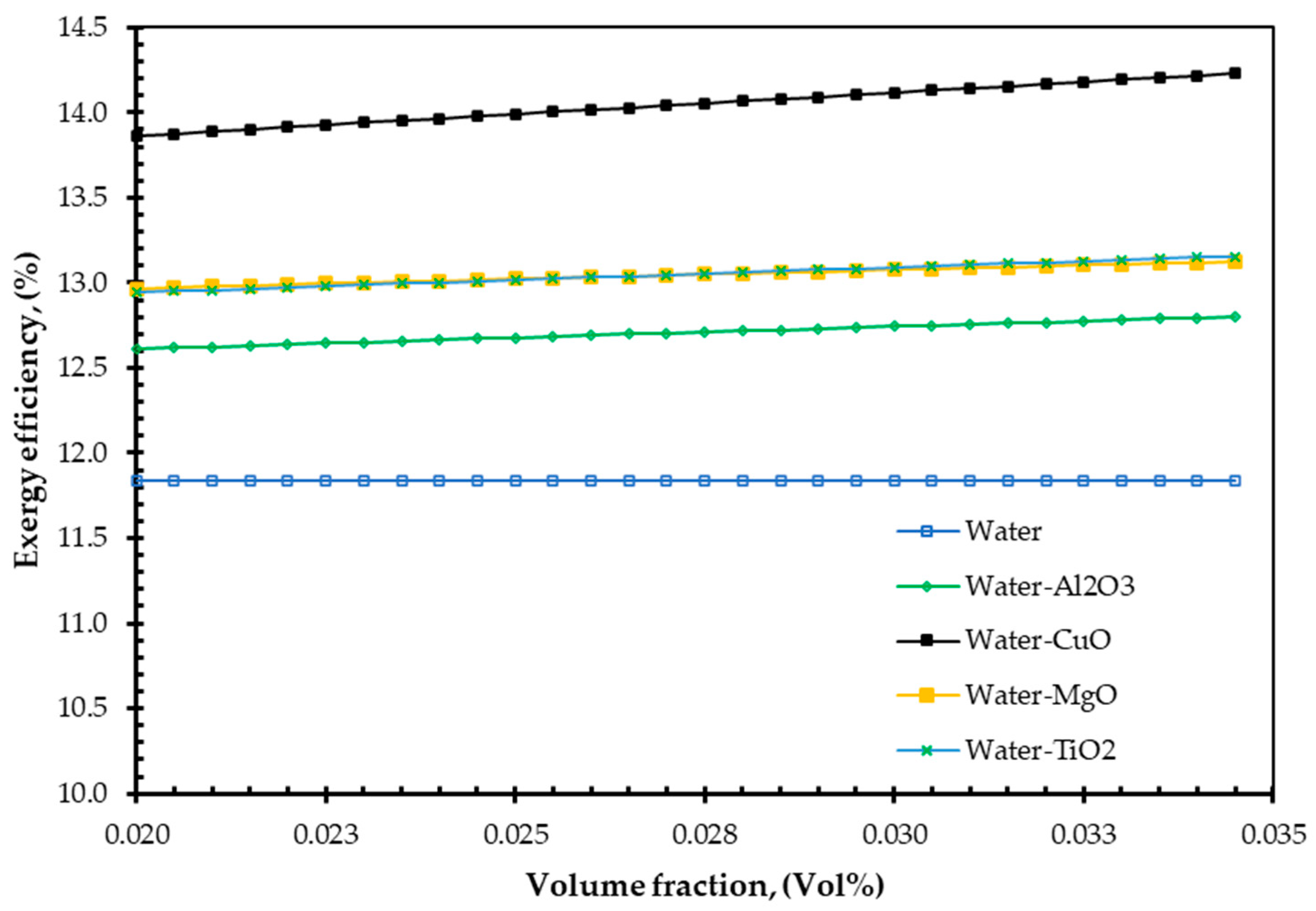
With an increase in particle concentration, the heat transfer rate is increased [56].
Figure 2 illustrates the changes of the energy efficiency of a FPSC as a function of the volume flow rate of 1 to 3.8 L/min. It can be seen from Figure 2 that the collector′s energy efficiency increases linearly and steadily with the increase of volume flow rate. Equation (9) and input data were used to calculate energy efficiency, considering output temperature difference constant and 2 vol % nanoparticles. It can be found from Figure 2 that the collector efficiency increases by 38.21% for CuO/water nanofluid and 34.17%, 33.21, and 32.91% for Al2O3/water MgO/water and TiO2/water nanofluids compared to the base fluid. These results satisfactorily agree with the results of Yousefi et al. [12] and Tyagi et al. [11].
Figure 3 shows the effect of output temperature on energy efficiency. Energy efficiency was calculated using Equation (9). It can be seen from Figure 3 that the energy efficiency increases significantly with increasing output temperature of all fluids. Solar collectors that utilise nanofluids have a higher output temperature, which produces nanoparticles in the basis fluid, and therefore have greater efficiency. The relevant definition is: “The heat needed to increase the temperature of a unit mass of a material by one unit of temperature”. As a result, at a similar heat flow rate, lower specific heat capacity material should offer higher temperature, as stated in the description.
The specific heat of nanofluids as a function of nanoparticle volume fraction is shown in Figure 4. When the nanoparticle volume fraction in the base fluid is higher, the specific heat is reduced. Due to these reasons, the overall output temperature and efficiency both increase. Figure 4 demonstrated the CuO nanofluid has a lower specific heat than Al2O3, MgO and TiO2 nanofluids for a given volume fraction. The relative heat of Al2O3 and TiO2 nanofluid was nearly identical. Even though the specific heat of these nanofluids varied, they were all above the specific heat of the base fluid. These findings are consistent with those of Kamyar et al. [57] and Sohel et al. [58].
The effect of nanoparticle volume fraction on exergy efficiency is illustrated in Figure 5. Equations (16), (17), (27) and (30) was used to calculate the exergy efficiency. The efficiency of solar collector increases linearly with the volume fraction. For example, for given nanoparticles of 3.2 vol %, the efficiency increases by 11.45% for CuO nanofluid, 9.7% for TiO2 nanofluid, and 9.35% for Al2O3 and 9.53% for MgO nanofluid compared to base fluid (water).
Exergy efficiency as the function of fluid volume flow rate is represented in Figure 6. The efficiency of exergy was determined using Equation (30). The analysis indicates that the exergy efficiency of a water operated collector is minimum; therefore, a good amount of irreversibility is present in the solar collector with water as the flowing medium. However, the figure shows that the exergy efficiency can be increased by using nanofluids as the flowing medium. As an absorbent medium, CuO nanofluid may be the right choice because the exergetic efficiency is better compared to the others nanofluids, and water. The TC of a nanofluid is an increasing function of nanoparticle volume fraction, according to the Hamilton and Crosser model [59]. It may be explained by increasing the effective surface area for heat transmission by increasing the volume fraction of nanoparticles. Additionally, the nanoparticles′ inherent the higher TC that improves the TC of nanofluids. This phenomenon may account for an increase in exergy efficiency.
Figure 7 represents the variation of analytically determined exergy efficiency of solar collectors with nanoparticles volume fraction. A solar collector using CuO/water nanofluid has the greatest exergy efficiency for the same flow rate as the others nanofluids. The CuO/water nanofluid along with solar collector, for example, has a 14.12% greater exergy efficiency than a typical solar collector operating on the water at a 2.4 L/s volume flow rate. Al2O3 and MgO show approximately equal exergy efficiency but higher than water. On the other hand, TiO2 provides slightly better exergy efficiency compared to base fluid, Al2O3 and MgO nanofluids. Thus, the analytical results indicate that the maximum exergy efficiency can be achieved with collectors using nanofluids as an agent medium. This improvement was most likely aided by the following factors: At a fixed Reynolds number, (I) the suspension TC increases as the volume fraction of nanoparticles, and (II) the nanofluids’ convective heat transfer coefficient is higher than that of the base fluid. Those similar conclusions were reported by Duangthongsuk and Wongwises [60], Xuan and Li [61], and He et al. [62]. When the collector absorbent surface area is identical, the mass flow rates and the specific heat may have a considerable effect on the exergetic efficiency of solar collectors, according to the exergy efficiency Equation (30).
Figure 8 depicts the density variations as a function of nanoparticle volume concentration. Equation (4) was used to compute density. As demonstrated in Figure 8, the mass flow rate of nanofluid rises as the volume percentage of nanoparticles increases; however, specific heat has the opposite effect. The following formula was used to determine the mass flow rate: relation, ṁ = Where, V represents a volume flow rate in L/min. The nanoparticles’ density and volume fraction of given geometrical dimensions are responsible for the variation in mass flow rate.
For instance, considering the volume flow rate of 1 lit/min, the mass flow rate was found to be 0.01667, 0.01824, 0.01840, 0.01825, and 0.01933 for water, Al2O3, TiO2, MgO, and CuO nanofluids, respectively for 3.2% nanoparticles volume concentration. This indicates that about an 11.45% increase in the mass flow rate is possible for CuO nanofluid than water. These findings are in agreement with the results published by Sohel et al. [58].
Although its outlet temperature has a more significant impact on energy efficiency, it raises the absorber plate temperature, potentially causing exergy loss. According to the literature, the leading cause of exergy loss in the collector is the temperature difference between the sun and absorber plate. If the temperature of the absorber plate rises, this disparity increases as well, resulting in the decrease of collector exergy loss. According to Jafarkazemi et al. [46], if the flow rate is increased by 0.01 kg/s it results in a significant reduction of temperature on the absorber plate. The heat loss coefficient reduces with the reduction of temperature between the absorber plate and the atmosphere, resulting in an improvement of the collector′s thermal efficiency. The argument is consistently endorsed by Figure 9. The mass flow rate was substantially improved by increasing the nanoparticle volume concentration.
The conventional working fluid and nanofluids can be compared for their contribution to total heat gain. After determining the thermal efficiency of a solar collector, the possibility for reducing the collector′s area can be calculated by [63]:
A c = m ˙ C p ( T f , o u t T f , i n ) I T ɳ
Figure 10 illustrated the size reduction of FPSC with a different working medium. The calculation is considered at nanoparticle of 0.032 vol % and volume flow rate of 2 L/min. The water-CuO working fluids shows the maximum decrease of FPSC size compared to others working medium. The difference of FPSC size reduction of water-CuO nanofluids with other nanofluids due to the higher EnE efficiency of water-CuO nanofluids.

5. Conclusions

The benefits of utilising various nanofluids in a FPSC were investigated in this research, considering the impacts of volume flow rate, nanoparticles volume fraction, mass flow rate, density, and specific heat on the solar collector′s EnE efficiency. Based on the results, the following main conclusions can be drawn.
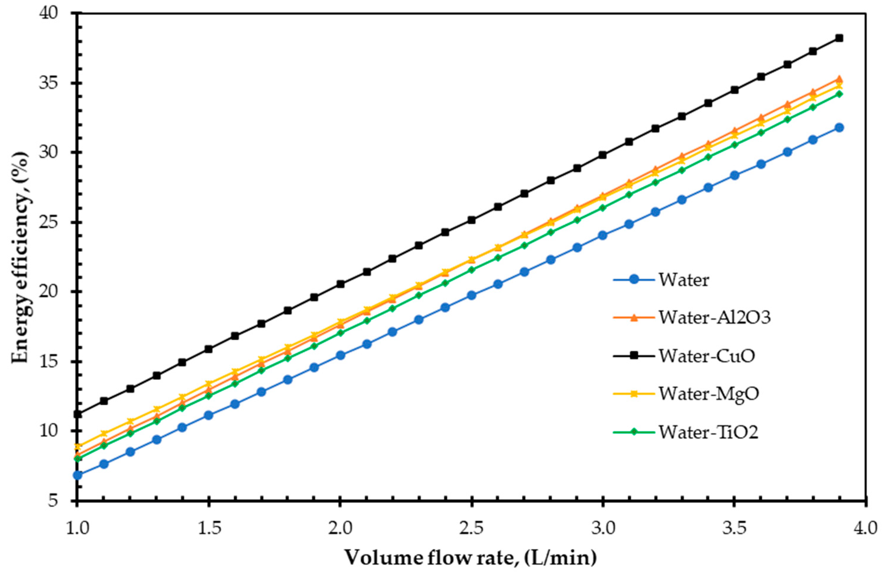
  • The analytical result shows CuO nanofluid increased the EnE efficiency of a FPSC by 38.21% and 14.86%, respectively.
  • Additionally, the study demonstrated that increasing volume fraction, mass flow rate, and density could improve EnE efficiency. Whenever the volume flow rate remains constant, the mass flow rate can be increased by adding nanoparticles into the base fluid, which has higher efficiency. Specific heat is one of the essential parameters for efficiency improvement. By reducing the specific heat of a fluid, the efficiency of a FPSC can be improved. It is simple to do so by suspending a small number of nanoparticles.
  • CuO nanofluid is a better option for increasing both the EnE efficiency of FPSC.
To reduce the complexity of the analysis, the overall heat loss coefficient, nanoparticle properties, inlet temperature, pressure drop, area of the absorber plate on the performance of the collector, heat removal factor, etc., were considered constant. This emphasises that more study is required for thoroughly investigating the heat transfer performance and efficiency of FPSC with nanofluids.

Author Contributions

R.M.M. conceived, designed, analysed the results, and wrote the paper; M.G.R. managed project administration and edited the draft; M.N.N. advised the project work and revised the draft. All authors have read and agreed to the published version of the manuscript.

Funding

This research received no external funding.

Institutional Review Board Statement

Not applicable.

Informed Consent Statement

Not applicable.

Data Availability Statement

Availability on request, case by case.

Acknowledgments

This research is supported by The Clean Energy Academy and International Excellence Award from Central Queensland University, Australia.

Conflicts of Interest

The authors declare no conflict of interest.

Nomenclature

Apabsorption area, m2
Cpspecific heat, J/kg·K
eexergy loss
E g ˙ exergy gain rate per unit area, W/m2
FRheat removal factor
F’collector efficiency factor
ggravitational acceleration, m/s2
ITincident solar energy per unit area, W/m2
kheat conductivity, W/m·K
mass flow rate, kg/s
Pmechanical power, W
Q ˙ thermal energy rate, W
Q u ˙ energy gain rate, W
sentropy per unit mass, J/kg·K
Sabsorbed irradiation, W/m2
Ttemperature, K
Tcabsorber plate temperature, K
U1overall heat loss, W/m2 K
Vvolume flow rate, L/min
zheight from reference level, m
EnEenergy and exergy
FPSCflat plate solar collector
DACdirective solar collector
CNTcarbon nanotube
TCThermal conductivity
ηEnenergy efficiency
ηExexergy efficiency
ηooptical efficiency
τtransmittance
αabsorptance
φnanoparticles volume fraction, %
ρdensity, kg/m3
σ overall entropy production, J/kg·K
Subscript
aambient
bfbase fluid
destdestruction
fininlet fluid
foutoutlet fluid
npnanoparticles
nfnanofluid

References

  1. Dziadik, P.C. Solar energy collection system and components. Google Patents Patent No. US 8,173,888B2, 8 May 2012. [Google Scholar]
  2. Mahian, O.; Kianifar, A.; Kalogirou, S.A.; Pop, I.; Wongwises, S. A review of the applications of nanofluids in solar energy. Int. J. Heat Mass Transf. 2013, 57, 582–594. [Google Scholar] [CrossRef]
  3. Kostić, L.T.; Pavlović, Z.T. Optimal position of flat plate reflectors of solar thermal collector. Energy Build. 2012, 45, 161–168. [Google Scholar] [CrossRef]
  4. Otanicar, T.P. Direct Absorption Solar Thermal Collectors Utilising Liquid-Nanoparticle Suspensions; Arizona State University: Tempe, AZ, USA, 2009. [Google Scholar]
  5. Yousefi, T.; Shojaeizadeh, E.; Veysi, F.; Zinadini, S. An experimental investigation on the effect of pH variation of MWCNT–H2O nanofluid on the efficiency of a flat-plate solar collector. Sol. Energy 2012, 86, 771–779. [Google Scholar] [CrossRef]
  6. Wang, X.-Q.; Mujumdar, A.S. Heat transfer characteristics of nanofluids: A review. Int. J. Therm. Sci. 2007, 46, 1–19. [Google Scholar] [CrossRef]
  7. Xuan, Y.; Li, Q. Heat transfer enhancement of nanofluids. Int. J. Heat Fluid Flow 2000, 21, 58–64. [Google Scholar] [CrossRef]
  8. Choi, S.U.; Eastman, J.A. Enhancing Thermal Conductivity of Fluids with Nanoparticles; Argonne National Lab.: Lemont, IL, USA, 1995. [Google Scholar]
  9. Fotukian, S.; Esfahany, M.N. Experimental investigation of turbulent convective heat transfer of dilute γ-Al2O3/water nanofluid inside a circular tube. Int. J. Heat Fluid Flow 2010, 31, 606–612. [Google Scholar] [CrossRef]
  10. Natarajan, E.; Sathish, R. Role of nanofluids in solar water heater. Int. J. Adv. Manuf. Technol. 2009, 1–5. [Google Scholar] [CrossRef]
  11. Tyagi, H.; Phelan, P.; Prasher, R. Predicted efficiency of a low-temperature nanofluid-based direct absorption solar collector. J. Sol. Energy Eng. 2009, 131, 041004. [Google Scholar] [CrossRef]
  12. Yousefi, T.; Veysi, F.; Shojaeizadeh, E.; Zinadini, S. An experimental investigation on the effect of Al2O3–H2O nanofluid on the efficiency of flat-plate solar collectors. Renew. Energy 2012, 39, 293–298. [Google Scholar] [CrossRef]
  13. Otanicar, T.P.; Golden, J.S. Comparative environmental and economic analysis of conventional and nanofluid solar hot water technologies. Environ. Sci. Technol. 2009, 43, 6082–6087. [Google Scholar] [CrossRef]
  14. Otanicar, T.P.; Phelan, P.E.; Prasher, R.S.; Rosengarten, G.; Taylor, R.A. Nanofluid-based direct absorption solar collector. J. Renew. Sustain. Energy 2010, 2, 033102. [Google Scholar] [CrossRef] [Green Version]
  15. Ziyadanogullari, N.B.; Yucel, H.; Yildiz, C. Thermal performance enhancement of flat-plate solar collectors by means of three different nanofluids. Therm. Sci. Eng. Prog. 2018, 8, 55–65. [Google Scholar] [CrossRef]
  16. Said, Z.; Saidur, R.; Rahim, N. Energy and exergy analysis of a flat plate solar collector using different sizes of aluminium oxide based nanofluid. J. Clean. Prod. 2016, 133, 518–530. [Google Scholar] [CrossRef]
  17. Said, Z.; Saidur, R.; Sabiha, M.; Hepbasli, A.; Rahim, N. Energy and exergy efficiency of a flat plate solar collector using pH treated Al2O3 nanofluid. J. Clean. Prod. 2016, 112, 3915–3926. [Google Scholar] [CrossRef]
  18. Sundar, L.S.; Singh, M.K.; Punnaiah, V.; Sousa, A.C. Experimental investigation of Al2O3/water nanofluids on the effectiveness of solar flat-plate collectors with and without twisted tape inserts. Renew. Energy 2018, 119, 820–833. [Google Scholar] [CrossRef]
  19. Hawwash, A.; Rahman, A.K.A.; Nada, S.; Ookawara, S. Numerical investigation and experimental verification of performance enhancement of flat plate solar collector using nanofluids. Appl. Therm. Eng. 2018, 130, 363–374. [Google Scholar] [CrossRef]
  20. Moghadam, A.J.; Farzane-Gord, M.; Sajadi, M.; Hoseyn-Zadeh, M. Effects of CuO/water nanofluid on the efficiency of a flat-plate solar collector. Exp. Therm. Fluid Sci. 2014, 58, 9–14. [Google Scholar] [CrossRef]
  21. Genc, A.M.; Ezan, M.A.; Turgut, A. Thermal performance of a nanofluid-based flat plate solar collector: A transient numerical study. Appl. Therm. Eng. 2018, 130, 395–407. [Google Scholar] [CrossRef]
  22. Nasrin, R.; Alim, M. Semi-empirical relation for forced convective analysis through a solar collector. Sol. Energy 2014, 105, 455–467. [Google Scholar] [CrossRef]
  23. Shojaeizadeh, E.; Veysi, F.; Kamandi, A. Exergy efficiency investigation and soptimisation of an Al2O3–water nanofluid based Flat-plate solar collector. Energy Build. 2015, 101, 12–23. [Google Scholar] [CrossRef]
  24. Kiliç, F.; Menlik, T.; Sözen, A. Effect of titanium dioxide/water nanofluid use on thermal performance of the flat plate solar collector. Solar Energy 2018, 164, 101–108. [Google Scholar] [CrossRef]
  25. Said, Z.; Sabiha, M.; Saidur, R.; Hepbasli, A.; Rahim, N.A.; Mekhilef, S.; Ward, T. Performance enhancement of a flat plate solar collector using titanium dioxide nanofluid and polyethylene glycol dispersant. J. Clean. Prod. 2015, 92, 343–353. [Google Scholar] [CrossRef]
  26. Jouybari, H.J.; Saedodin, S.; Zamzamian, A.; Nimvari, M.E.; Wongwises, S. Effects of porous material and nanoparticles on the thermal performance of a flat plate solar collector: An experimental study. Renew. Energy 2017, 114, 1407–1418. [Google Scholar] [CrossRef]
  27. Faizal, M.; Saidur, R.; Mekhilef, S.; Hepbasli, A.; Mahbubul, I. Energy, economic, and environmental analysis of a flat-plate solar collector operated with SiO2 nanofluid. Clean Technol. Environ. Policy 2015, 17, 1457–1473. [Google Scholar] [CrossRef] [Green Version]
  28. Meibodi, S.S.; Kianifar, A.; Niazmand, H.; Mahian, O.; Wongwises, S. Experimental investigation on the thermal efficiency and performance characteristics of a flat plate solar collector using SiO2/EG–water nanofluids. Int. Commun. Heat Mass Transf. 2015, 65, 71–75. [Google Scholar] [CrossRef]
  29. Cengel, Y.A.; Boles, M.A. Thermodynamics: An Engineering Approach 6th Editon (SI Units); The McGraw-Hill Companies, Inc.: New York, NY, USA, 2007. [Google Scholar]
  30. Saidur, R.; BoroumandJazi, G.; Mekhlif, S.; Jameel, M. Exergy analysis of solar energy applications. Renew. Sustain. Energy Rev. 2012, 16, 350–356. [Google Scholar] [CrossRef]
  31. Farahat, S.; Sarhaddi, F.; Ajam, H. Exergetic soptimisation of flat plate solar collectors. Renew. Energy 2009, 34, 1169–1174. [Google Scholar] [CrossRef]
  32. Alim, M.A.; Abdin, Z.; Saidur, R.; Hepbasli, A.; Khairul, M.A.; Rahim, N.A. Analyses of entropy generation and pressure drop for a conventional flat plate solar collector using different types of metal oxide nanofluids. Energy Build. 2013, 66, 289–296. [Google Scholar] [CrossRef]
  33. Ge, Z.; Wang, H.; Wang, H.; Zhang, S.; Guan, X. Exergy Analysis of Flat Plate Solar Collectors. Entropy 2014, 16, 2549–2567. [Google Scholar] [CrossRef]
  34. Akram, N.; Sadri, R.; Kazi, S.; Zubir, M.N.M.; Ridha, M.; Ahmed, W.; Soudagar, M.E.M.; Arzpeyma, M. A comprehensive review on nanofluid operated solar flat plate collectors. J. Therm. Anal. Calorim. 2020, 139, 1309–1343. [Google Scholar] [CrossRef]
  35. Zayed, M.; Zhao, J.; Du, Y.; Kabeel, A.; Shalaby, S. Factors affecting the thermal performance of the flat plate solar collector using nanofluids: A review. Sol. Energy 2019, 182, 382–396. [Google Scholar] [CrossRef]
  36. Said, Z.; Hachicha, A.A.; Aberoumand, S.; Yousef, B.A.; Sayed, E.T.; Bellos, E. Recent advances on nanofluids for low to medium temperature solar collectors: Energy, exergy, economic analysis and environmental impact. Prog. Energy Combust. Sci. 2021, 84, 100898. [Google Scholar] [CrossRef]
  37. Alawi, O.A.; Kamar, H.M.; Mallah, A.; Mohammed, H.A.; Kazi, S.; Sidik, N.A.C.; Najafi, G. Nanofluids for Flat Plate Solar Collectors: Fundamentals and Applications. J. Clean. Prod. 2020, 291, 125725. [Google Scholar] [CrossRef]
  38. Henning, H.-M. Solar Air Conditioning and Refrigeration. Task 38 of the IEA (International Energy Agency) Solar Heating and Cooling Program. Available online: http://lmora.free.fr/task38/pdf/matin/Henning.pdf (accessed on 10 May 2011).
  39. Xuan, Y.; Roetzel, W. Conceptions for heat transfer correlation of nanofluids. Int. J. Heat Mass Transf. 2000, 43, 3701–3707. [Google Scholar] [CrossRef]
  40. Zhou, S.-Q.; Ni, R. Measurement of the specific heat capacity of water-based Al2O3 nanofluid. Appl. Phys. Lett. 2008, 92, 093123. [Google Scholar] [CrossRef]
  41. Struckmann, F. Analysis of a Flat-Plate Solar Collector. 2008. Available online: http://www.ht.energy.lth.se/fileadmin/ht/Kurser/MVK160/Project_08/Fabio.pdf (accessed on 10 May 2021).
  42. Sukhatme, S.P.; Nayak, J. Solar Energy; McGraw-Hill Education: New York, NY, USA, 2017. [Google Scholar]
  43. Luminosu, I.; Fara, L. Determination of the optimal operation mode of a flat solar collector by exergetic analysis and numerical simulation. Energy 2005, 30, 731–747. [Google Scholar] [CrossRef]
  44. Sarhaddi, F.; Farahat, S.; Ajam, H.; Behzadmehr, A. Exergetic performance assessment of a solar photovoltaic thermal (PV/T) air collector. Energy Build. 2010, 42, 2184–2199. [Google Scholar] [CrossRef]
  45. Suzuki, A. A fundamental equation for exergy balance on solar collectors. J. Sol. Energy Eng. 1988, 110, 102–106. [Google Scholar] [CrossRef]
  46. Jafarkazemi, F.; Ahmadifard, E. Energetic and exergetic evaluation of flat plate solar collectors. Renew. Energy 2013, 56, 55–63. [Google Scholar] [CrossRef]
  47. Jeter, S.M.; Stephens, J.H. Systems and methods of thermal energy storage and release. Google Patents Patent No. US 2012/0132398 A1, 31 May 2012. [Google Scholar]
  48. Bejan, A. Entropy Generation through Heat and Fluid Flow; Wiley: New York, NY, USA, 1982; Volume 1. [Google Scholar]
  49. Duffie, J.A.; Beckman, W.A. Solar Engineering of Thermal Processes; John Wiley & Sons: Hoboken, NJ, USA, 2013. [Google Scholar]
  50. Pandey, S.D.; Nema, V. Experimental analysis of heat transfer and friction factor of nanofluid as a coolant in a corrugated plate heat exchanger. Exp. Therm. Fluid Sci. 2012, 38, 248–256. [Google Scholar] [CrossRef]
  51. Moghaddami, M.; Mohammadzade, A.; Esfehani, S.A.V. Second law analysis of nanofluid flow. Energy Convers. Manag. 2011, 52, 1397–1405. [Google Scholar] [CrossRef]
  52. Amini, M.; Kianifar, A. An Analytical Study on Energy and Exergy of a Minichannel-Based Solar Collector Using Fe3O4 and MgO/Water Nanofluids. In Proceedings of the International Conference on researches in Science and Engineering, Istanbul, Turkey, 28 July 2016. [Google Scholar]
  53. Verma, S.K.; Tiwari, A.K.; Chauhan, D.S. Experimental evaluation of flat plate solar collector using nanofluids. Energy Convers. Manag. 2017, 134, 103–115. [Google Scholar] [CrossRef]
  54. Elcioglu, E.B.; Genc, A.M.; Karadeniz, Z.H.; Ezan, M.A.; Turgut, A. Nanofluid figure-of-merits to assess thermal efficiency of a flat plate solar collector. Energy Convers. Manag. 2020, 204, 112292. [Google Scholar] [CrossRef]
  55. Stalin, P.M.J.; Arjunan, T.; Matheswaran, M.; Dolli, H.; Sadanandam, N. Energy, economic and environmental investigation of a flat plate solar collector with CeO2/water nanofluid. J. Therm. Anal. Calorim. 2020, 139, 3219–3233. [Google Scholar] [CrossRef]
  56. Lelea, D. The performance evaluation of Al2O3/water nanofluid flow and heat transfer in microchannel heat sink. Int. J. Heat Mass Transf. 2011, 54, 3891–3899. [Google Scholar] [CrossRef]
  57. Kamyar, A.; Saidur, R.; Hasanuzzaman, M. Application of Computational Fluid Dynamics (CFD) for nanofluids. Int. J. Heat Mass Transf. 2012, 55, 4104–4115. [Google Scholar] [CrossRef]
  58. Sohel, M.R.; Saidur, R.; Sabri, M.F.M.; Kamalisarvestani, M.; Elias, M.M.; Ijam, A. Investigating the heat transfer performance and thermophysical properties of nanofluids in a circular micro-channel. Int. Commun. Heat Mass Transf. 2013, 42, 75–81. [Google Scholar] [CrossRef]
  59. Hamilton, R.L.; Crosser, O.K. Thermal Conductivity of Heterogeneous Two-Component Systems. Ind. Eng. Chem. Fundam. 1962, 1, 187–191. [Google Scholar] [CrossRef]
  60. Duangthongsuk, W.; Wongwises, S. Heat transfer enhancement and pressure drop characteristics of TiO2–water nanofluid in a double-tube counter flow heat exchanger. Int. J. Heat Mass Transf. 2009, 52, 2059–2067. [Google Scholar] [CrossRef]
  61. Xuan, Y.; Li, Q. Investigation on Convective Heat Transfer and Flow Features of Nanofluids. J. Heat Transf. 2003, 125, 151–155. [Google Scholar] [CrossRef] [Green Version]
  62. He, Y.; Jin, Y.; Chen, H.; Ding, Y.; Cang, D.; Lu, H. Heat transfer and flow behaviour of aqueous suspensions of TiO2 nanoparticles (nanofluids) flowing upward through a vertical pipe. Int. J. Heat Mass Transf. 2007, 50, 2272–2281. [Google Scholar] [CrossRef]
  63. Faizal, M.; Saidur, R.; Mekhilef, S. Potential of size reduction of flat-plate solar collectors when applying MWCNT nanofluid. IOP Conf. Ser. Earth Environ. Sci. 2013, 16, 012004. [Google Scholar] [CrossRef]
Figure 1. A schematic diagram for different exergy losses.
Energies 14 04305 g001
Figure 2. Effect of volume flow rate on energy efficiency.
Energies 14 04305 g002
Figure 3. Effect of output temperature on collector energy efficiency.
Energies 14 04305 g003
Figure 4. Effect of volume fraction on specific heat.
Energies 14 04305 g004
Figure 5. Effect of volume fraction on exergy efficiency.
Energies 14 04305 g005
Figure 6. Effect of volume flow rate on exergy efficiency.
Energies 14 04305 g006
Figure 7. Effect of particle volume fraction on exergy efficiency.
Energies 14 04305 g007
Figure 8. Effect of volume fraction on density.
Energies 14 04305 g008
Figure 9. Effect of particle volume fraction on mass flow rate.
Energies 14 04305 g009
Figure 10. FPSC size reduction with different working fluids.
Energies 14 04305 g010
Table 1. Literature review summary on FPSC using different.
ReferencesModelBase FluidNanoparticles’ SpecificationOptimum Parameters
Particle NameVolume Fractions (Vol %)Size (nm)Mass Flow Rate (kg/min)Improvement of Efficiency (%)Flow RegimeFPSC Surface Area (m2)
Sundar et al. [18]ExperimentalWaterAl2O30.1 and 0.320518Turbulent2
Hawwash et al. [19]Experimental and Numerical (CFD ansys fluent)DWAl2O30.1 and 0.3205.5118Turbulent2.1
Mogahadam et al. [20]ExperimentalWaterCuO0.440121.8Laminar1.88
Genc et al. [21]Numerical (Matlab)WaterAl2O30.1, 0.2 and 0.3 3.69.5Laminar1.99
Nasrin and Alim [22]ExperimentalDWAl2O3, CuO and TiO20.2, 0.4 and 0.850, 50 and 25471, 87.8 and 52.5Laminar1.51
Shojaeizadeh et al. [23]Experimental and NumericalDI waterAl2O3
SDBS
0.090696, 0.094583, 0.10293, 0.11057, 0.117686, 0.1244, 0.13082, 0.137, and 0.1423152.570Turbulent1.51
Kilic et al. [24]ExperimentalWaterTiO2
Triton X-100
0.244234.43Turbulent1.82
Said et al. [25]ExperimentalPEG-400TiO20.1 and 0.3210.576.6Laminar1.84
Jouybari et al. [26]ExperimentalWaterSiO20.2, 0.4, and 0.671.58Laminar0.8
Faizal et al. [27]ExperimentalWaterSiO20.2, 0.4, and 0.610323.5Turbulent2
Meibodi et al. [28]ExperimentalEG–waterSiO20.5, 0.75, and 1102.78Turbulent1.59
Table 2. Properties of different nanoparticle and base fluid [50,51,52].
NanoparticlesSpecific Heat, Cp
(J/kg·K)
Thermal Conductivity, k
(W/m·K)
Density, ρ
(kg/m3)
Alumina (Al2O3)773403960
Copper oxide (CuO)551336000
Titanium oxide (TiO2)6928.44230
Magnesium oxide (MgO)955453560
Water (H2O), base fluid41820.60997
Table 3. Characteristic parameters for two kinds of solar collector [45].
Solar Collector TypeOptical Efficiency, ηoOverall Heat Loss,
U1 (W/m2 K)
Collector Efficiency Factor, F′
Evacuated tube0.471.10.99
Flat plate0.825.00.97
Table 4. Environmental and analysis conditions for the FPSC.
Parameters of CollectorValue
TypeBlack paint flat plate
GlazingSingle glass
Agent fluidsWater, Al2O3, MgO2, TiO2 and CuO nanofluids
Absorption area (m2)1.44
Wind speed (m/s)20
Collector till (°)20
Fluid inlet and ambient temperature (K)300
Apparent sun temperature (K)4350
Optical efficiency84%
Emissivity of the absorber plate0.95
Emissivity of the covers0.90
Glass thickness (mm)4
Insulation TC (W/m∙K)0.06
Incident solar energy per unit area of the absorber plate (W/m2)500
Inner diameter of pipes (m)0.005
Table 5. EnE efficiency enhancement compared to the base fluid.
Absorbing MediumMaximum ηEn Enhancement, (%)Maximum ηEx Enhancement, (%)
φ = 2% and Diff. Volume Flow Rateφ = 3.20% and V = 1 L/sφ = 2% and V = 2.40 L/sφ = 3.20% and V = 1 L/s
CuO nanofluid38.2116.8014.8611.45
TiO2 nanofluid34.179.2512.649.70
MgO nanofluid34.779.7112.569.53
Al2O3 nanofluid35.329.1811.119.35
Table 6. Comparison among the present analysis, experimental results, and computer simulation.
Tf, in or Ta, (k)IT, (W/m2)S, (W/m2)ΔT, (K)ηEx, (%)
Present analysis (CuO)300.0050042062.003.35
Alim et al. [32]300.00100050063.003.72
Luminosu and Fara [43]305.1578858046.002.90
Farahat and Sarhaddi [31]300.0050042058.822.95
Publisher’s Note: MDPI stays neutral with regard to jurisdictional claims in published maps and institutional affiliations.

