Article

A Frequency Adaptive Scheme Based on Newton Structure of PRRC for LCL-Type Inverter Connected with Weak Grid

College of Electrical Engineering, Sichuan University, Chengdu 610065, China
*
Author to whom correspondence should be addressed.
Energies 2021, 14(14), 4225; https://doi.org/10.3390/en14144225
Submission received: 11 June 2021 / Revised: 21 June 2021 / Accepted: 9 July 2021 / Published: 13 July 2021

Abstract

:
Repetitive control (RC) is gradually used in inverters tied with weak grid. To achieve the zero steady-state error tracking of inverter current and compensate the harmonic distortion caused by frequency fluctuation, a frequency adaptive (FA) control scheme for LCL-type inverter connected with weak grid is proposed. This scheme adopts a proportional resonance (PR) controller in parallel with RC (PRRC) to overcome the disadvantages caused by RC inherent one-cycle time delay. A fractional delay (FD) filter based on the Newton structure is proposed to approximate the fraction item of fs/f, where fs and f are sample frequency and grid frequency, respectively. The structure of the proposed FD filter is relatively simple; moreover, coefficients of the filter maintain constant so as not to need online tuning even when grid frequency fluctuates, which decreases the computational burden considerably. The feasibility and effectiveness of the proposed FA control scheme, named as Newton-FAPRRC, are all verified by the simulation and experimental results.

Graphical Abstract

1. Introduction

With the growing increase of distributed generation (DG) penetration [1,2], the impedance of conventional ideal grid can no longer be ignored and the grid presents the characteristics of weak grid [3,4]. Under the weak grid condition, the current harmonics of grid-connected inverter will be further amplified and grid frequency fluctuation will be more serious than ideal grid, which may even lead to the problems of system stability. To improve the power quality, control schemes of grid-connected inverter have been investigated extensively and many controllers are developed, such as proportional integral (PI) controller [5,6], proportional resonant (PR) controller [6,7], deadbeat (DB) controller [8], RC [9,10,11], etc.
The PI control is widely used for inverters due to its relatively easy implementation [6]. However, limited by the control gain, PI control cannot achieve zero steady-state error tracking for periodic signals in α , β coordinate [12]. To improve control accuracy, a common method is to transfer state variable equations to dq coordinate. However, mutual coupling of the d-axis and q-axis equations will significantly increase the complexity of controller design [13]. PR control can achieve zero steady-state error tracking for periodic signals of a specific frequency (resonant frequency of the PR controller) in the α , β coordinate due to its infinite gain at the resonant frequency. However, the disadvantage of PR is that it is difficult to suppress the periodic harmonics that are not of the resonance frequency of PR [7,14]. Multi-PR control is proposed, i.e., several resonant controllers are parallel connected and every resonant controller responds for the suppression of a harmonic at a specific resonance frequency [15]. Obviously, this scheme is complex because the control effect depends on the large number of resonant controllers. Moreover, if any harmonic with unexpected resonant frequency while having relatively large magnitude appears in the system, the control accuracy will be greatly deteriorated. DB control is a type of predictive control and has a fast response. However, it must be noticed that this scheme depends on the highly accuracy of system model [16]. In the weak grid condition, the grid impedance cannot be ignored and may fluctuate, which imposes critical requirements on impedance identification for the DB controller design.
At present, RC, which is based on the internal model principle, gains more attention due to its advantages such as high tracking accuracy of periodic signals, easy digital realization and parameters setting [17,18,19], etc. However, the inherent one-cycle time delay causes relatively poor dynamic characteristic of RC. Usually, to achieve fast dynamic response, RC is in parallel with other controllers [10,11], which is called as a composite control strategy. The composite control scheme of proportional control in parallel with RC (PRC) can effectively improve the dynamic response of the system, and the structure is relatively simple. However, the PRC scheme has the disadvantage of large steady-state tracking error [10]. A control scheme of PI in parallel with RC (PIRC) is proposed in [11] to improve the dynamic and steady-state performance of the system. However, as mentioned before, PI control only has zero steady-state error in the dq coordinate, which indicates that a complex decoupling transformation is indispensable to employ PIRC [11].
In the applying of RC, its digital form of z N 1 z N is usually adopted, where N = fs/f, fs and f are sample frequency and grid frequency respectively. RC has high gains at fundamental frequency and integer multiple harmonic frequencies when N is an integer, which means that RC can achieve the zero steady-state error tracking for periodic signals with these frequencies. However, when the grid frequency fluctuates, which is a common scene under weak grid condition, N is mainly a fractional when fs keeps constant. However, due to the limitation of the digital realization of the controller, N can only be an integer, therefore, the high tracking accuracy RC cannot be achieved. In order to solve this problem, [20] proposes a variable sampling frequency control scheme to keep N as an integer. However, the variable fs will affect other controllers in the system and also increase the complexity of real-time implementation. In order to avoid the disadvantages caused by the change of sampling frequency, a fractional delay filter based on Lagrange interpolation is proposed to approximate the FD item zd [21,22], where d is the fractional part of N. This scheme makes the resonant frequencies of RC track the fundamental and harmonic frequencies of the power grid by tuning the coefficients of the filter on-line. However, if the grid frequency fluctuates, all the coefficients of the FD filter will have to be recalculated and retuned, which greatly increases the computational burden. In [23], a FD filter based on Farrow structure is proposed, which effectively avoids the disadvantage as online calculation and reset of filter coefficients at the cost of the structure complexity.
To suppress the grid current harmonics of LCL-type inverter tied with weak grid and improve system stability, a novel frequency-adaptive of PRRC (FAPRRC) control scheme is proposed. Compared with PRC and PIRC, the PR in parallel with RC scheme is chosen due to its advantages of the control accuracy in the dynamic response process and the small control error due to the infinite gain of PR at a specific frequency [14]. FD filter based on the Newton structure is applied to approximate the FD. Comparing to FD filter based on Lagrange interpolation and Farrow structure, the proposed Newton FD filter has simple structure; moreover, its coefficients do not need to be tuned on-line even when frequency fluctuates severely. Both mathematical analysis and experimental results show that the proposed Newton-FAPRRC significantly improves the accuracy and stability of the LCL-type inverter tied with weak grid. The rest of this paper is organized as follows: Section 2 describes the structure of grid-connected inverter system and PRRC scheme. Section 3 presents the FD filter with the Newton structure. Section 4 gives the Newton-FAPRRC parameters setting. Section 5 analyzes the stability of Newton-FAPRRC in weak grid condition. Simulation and experimental results are shown in Section 6 to verify the effectiveness of the proposed scheme.

2. PRRC Control Scheme

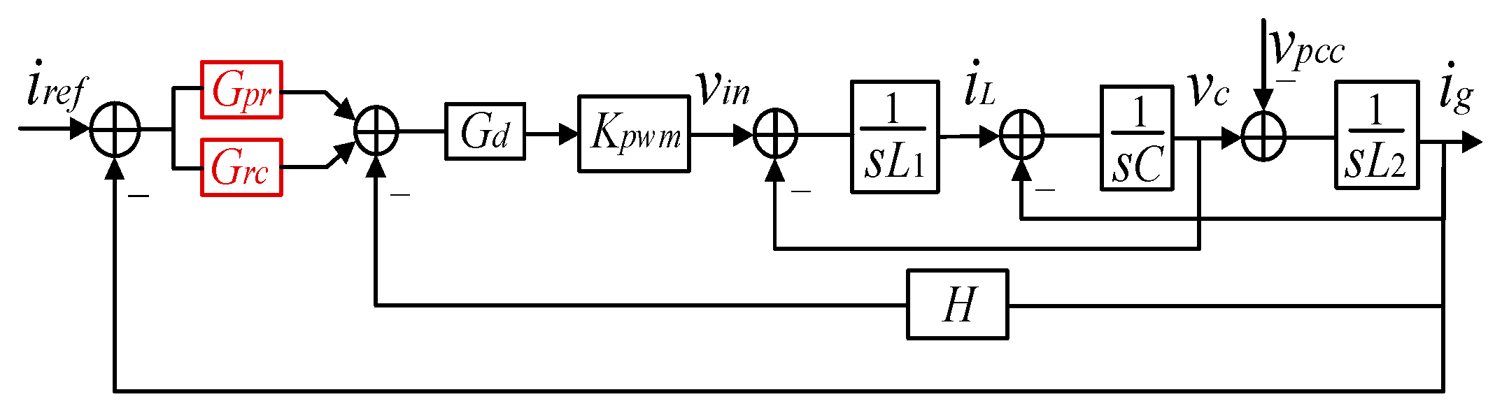
2.1. Configuration of LCL-Type Grid-Connected Inverter System
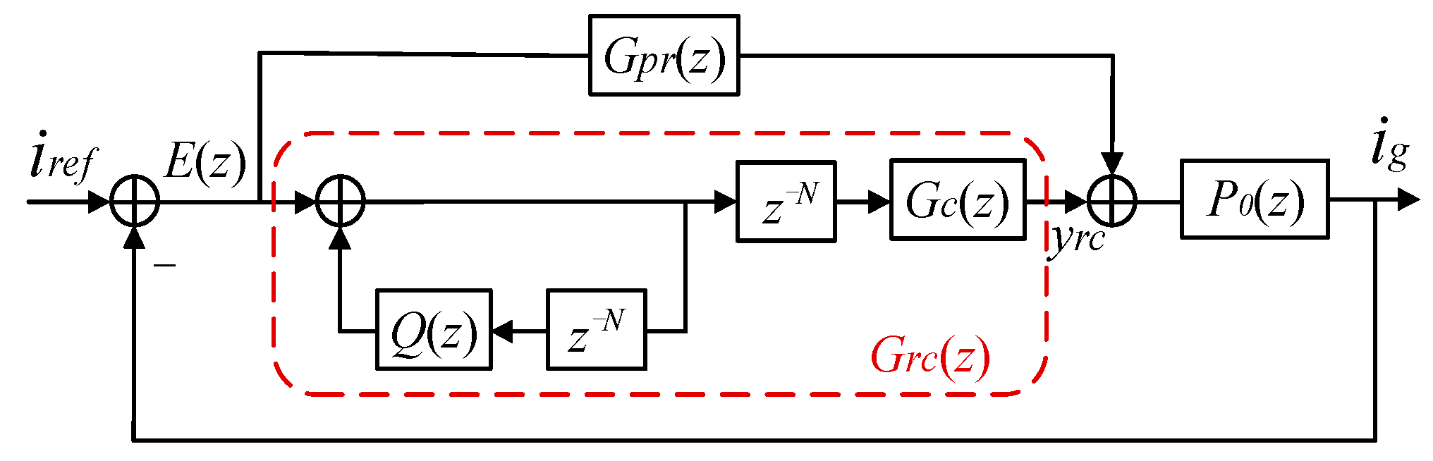
The configuration and control scheme of investigated inverter are shown in Figure 1.
C is the filter capacitor of LCL filter; L1 and L2 are the filter inductance of LCL filter; Zg is the grid impedance; iL, ig and ic are the output current of inverter, grid-connected current and capacitor current respectively; vc, vpcc and vg are the capacitor voltage, the voltage at the point of common coupling and grid voltage, respectively; The reference current iref of grid connected inverter is calculated from command Iref. GCFAD is the abbreviation of grid current feedback active damping, which is used to suppress the inherent resonance peak of LCL filter.

2.2. Proposed PRRC

Figure 2 shows the control structure diagram of grid-connected inverter, which adopts a control scheme of PR in parallel with RC (PRRC). Gpr and Grc are the transfer functions of PR control and RC, respectively; vin is the output voltage of inverter; H is the transfer function of GCFAD; kpwm is the gain of inverter bridges; Gd is the time delay of the system, which includes times of PWM transfer and program calculation. The expression of Gd is shown in (1) [1]; Tc is the sampling period.
G d ( s ) = e T c s ( 1 e T c s ) T c s
Actually, the adopted GCFAD is a high pass filter [24] and its one order expression is:
H ( s ) = k c s s + ω c
where kc is the gain and ωc is the cut-off frequency of the high pass filter.
According to Figure 3, the transfer function of LCL filter in s domain can be obtained.
G L C L ( s ) = 1 L 1 L 2 C s 3 + ( L 1 + L 2 ) s
Applying a bilinear transformation to (1), (2) and (3), the transfer function of the inner closed loop in z domain is:
P 0 ( z ) = K p w m G d ( z ) G L C L ( z ) 1 + K p w m G d ( z ) G L C L ( z ) H ( z )
Figure 3 is the control structure diagram of grid-connected LCL inverter in z domain, in which Q(z) is a constant introduced in the feedback branch to improve the stability of RC [25,26]. G c ( z ) is the compensator of RC, which is used to compensate the amplitude and phase of the equivalent control object of RC, i.e., the transfer function of ig to yrc.
The transfer functions of RC and PR in z-domain are as follows:
{ G r c ( z ) = z N 1 z N Q ( z ) G c ( z ) G p r ( z ) = k p + 4 k i ω i T c ( z 2 1 ) ( 4 + 4 ω i T c + ω 0 2 T c 2 ) z 2 + ( 2 ω 0 2 T c 2 8 ) z + ( 4 4 ω i T c + ω 0 2 T c 2 )
In (5), kp and ki are the proportional gain and integral gain of PR; ωi is the bandwidth of PR; ω0 is the grid angular frequency, and ω 0 = 2 π f .

3. Frequency Adaptation of RC

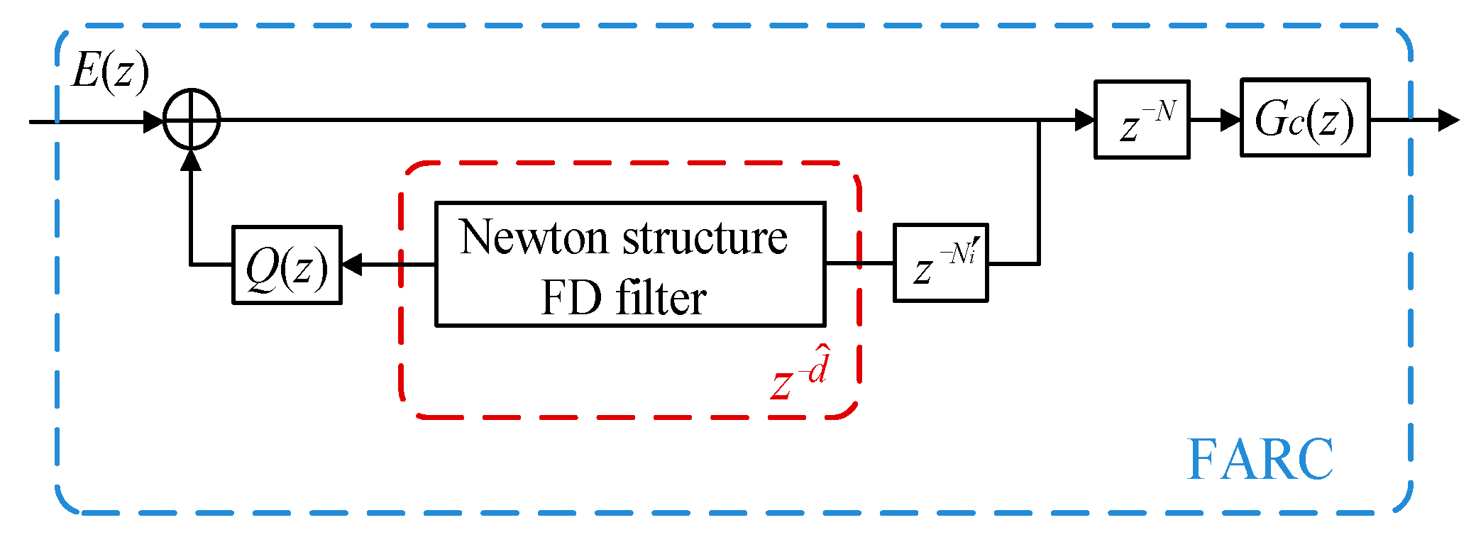
3.1. FARC Based on Newton Structure

For weak grids, f often fluctuates severely and N contains an integer term N i and a fractional term d. Therefore, the time delay z−N can be expressed as [27]:
z N = z N i z d
In this paper, a FD filter based on the Newton structure is proposed to approximate fractional delay item z d ^ , and frequency adaptation of RC (FARC) can be expected. The relationship of d ^ and d will be introduced in Section 3.2. and corresponding N i = N d ^ . The proposed scheme is shown in Figure 4.
It should be noted that there is also a z−N in the forward branch of RC, but it will only affect the phase of the system slightly due to high sampling frequency in this paper. Therefore, no FD compensation is made for it.

3.2. Transformation from Farrow to Newton

In order to realize the implementation of various interpolation methods in Newton structure and simplify the structure of FD filter, a Newton structure FD filter is derived from a Farrow structure, which is shown in Figure 4. The expression of Farrow structure [28] is represented as (7).
H F a r r o w ( d , z ) = D T C Z
In (7), D = [ 1 d d 2 d M 1 ] T ; Z = [ 1 z 1 z 2 z N + 1 ] T ; M is the number of the sub-filters contained in Farrow FD filter; (N-1) is the order of sub-filter; and C is the coefficient matrix of Farrow FD filter.
The expression of Newton structure [28] can be represented as (8).
H N e w t o n ( d ^ , z ) = D ^ T C ^ Z ^
In (8), D ^ = [ 1 d ^ d ^ ( d ^ 1 ) i = 0 M 2 ( d ^ i ) ] T ; d ^ = d ¯ + M 1 2 , d ^ [ 1 , 2 ] ; d ¯ = d 0.5 ; Z ^ = [ 1 1 z 1 ( 1 z 1 ) 2 ( 1 z 1 ) N 1 ] T ; and C ^ is the coefficient matrix of Newton FD filter.
The transformation from Farrow structure to Newton structure can be realized by (9).
H F a r r o w ( d , z ) = D T C Z = D T ( T d T T d T ) C ( T z 1 T z ) Z = ( T d D ) T ( T d T C T z 1 ) ( T z Z ) = D ^ T C ^ Z ^ = H N e w t o n ( d ^ , z )
where T d and T z are the transformation matrices that transform D and Z into D ^ and Z ^ , respectively. D ^ = T d D , C ^ = T d T C T z 1 , Z ^ = T z Z , T d T = ( T d T ) 1 . Transformation matrix T d can be calculated as:
T d = T d T d
In (10), T d is the matrix with each row i containing the coefficients of the polynomial ( d ¯ + M 1 2 ) i 1 , and elements of the matrix T d are calculated by (11):
T d [ i , j ] = ( i 1 j 1 ) ( M 1 2 ) i j
The elements in the matrix T d are the Stirling numbers of the first kind S j ( i ) , i.e., T d [ i , j ] = S j ( i ) .
Transformation matrix can be expressed as follows:
T z [ i , j ] = ( i 1 j 1 ) ( 1 ) j + 1

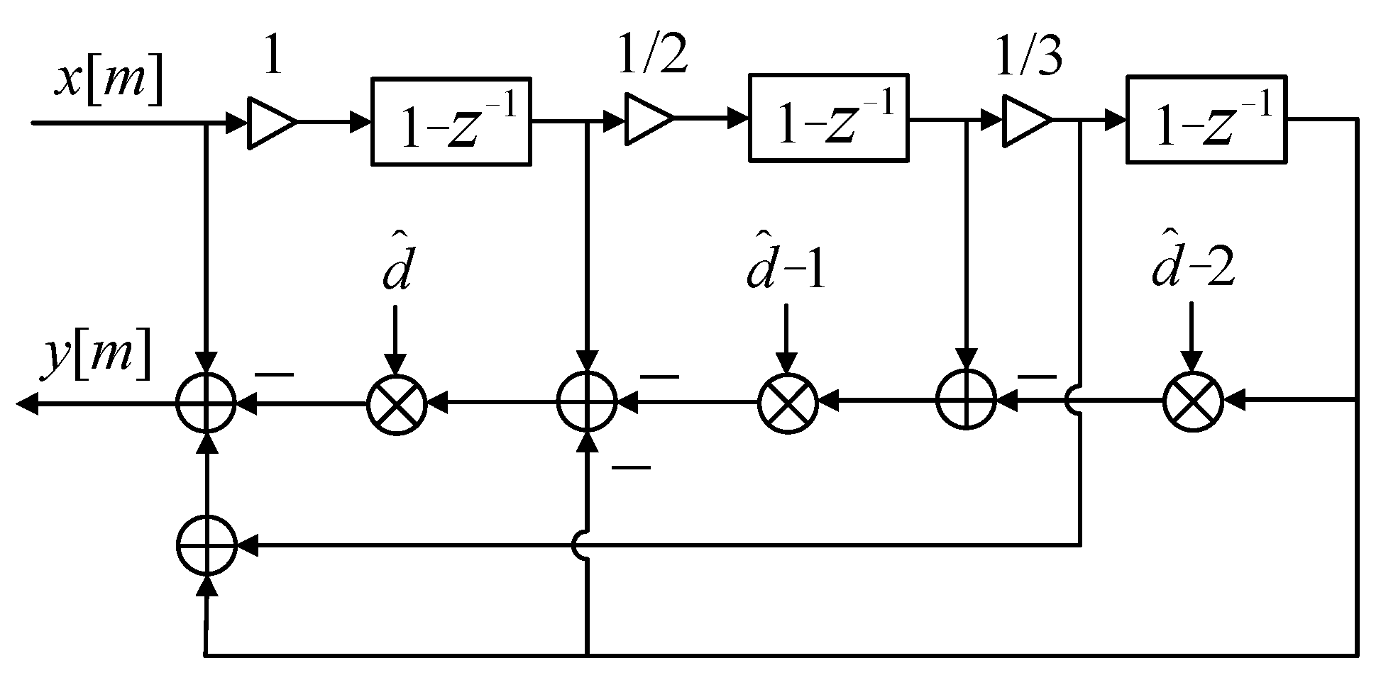
3.3. Three-Order Newton FD Filter

Because the third-order filter has the best trade-off between structure complexity and approximate effect [29,30], M, N are set the value of 4. The coefficient matrix Cspline of the third-order filter with Farrow structure is calculated by using spline interpolation and is shown as (13) [29]:
C s p l i n e = [ 1 23 23 1 6 30 30 6 12 12 12 12 8 24 24 8 ]
The coefficient matrix of the third-order FD filter based on Newton structure can be obtained as (14).
C ^ = T d T C s p l i n e T z 1 = ( T d T d ) T C s p l i n e T z 1 = [ 1 0 1 / 6 1 / 6 0 1 0 1 / 6 0 0 1 / 2 0 0 0 0 1 / 6 ]
The structure of third-order Newton FD filter can be obtained as Figure 5.
According to Figure 5, the proposed Newton FD filter has the characteristics of constant coefficients and relatively simple structure, which significantly reduces the computational burden and implementation complexity [31].

3.4. Performance Analysis of Newton-FAPRRC

To verify the performance of proposed Newton-FAPRRC, the amplitude frequency characteristics of conventional PRRC (CPRRC) and Newton-FAPRRC are both shown in Figure 6.
In this paper, M = 4, so d ^ = d + 1 , N i = N d ^ = N i 1 in Figure 4. Taking 7th harmonic as an example, if grid frequency is 49.2 Hz, N = f s / f = 203.25 , z−N can be expressed as z N = z 202 z 1.25 , d ^ = 1.25 ,   N i = 202 . It can be seen that the amplitude of Newton-FAPRRC is 31 dB at 7th harmonic frequency (f = 344.4 Hz), while the amplitude of CPRRC is 27 dB. If grid frequency is 50.8 Hz, the amplitude of CPRRC is considerably reduced to 18 dB while Newton-FAPRRC keeps unchanged. The same conclusions also can be drawn for other harmonics having different frequencies. It is obviously that the tracking effect of Newton-FAPRRC is much better than CPRRC due to its higher amplitude when grid frequency fluctuates severely.

4. Parameters of PRRC

From Figure 3, the closed-loop transfer function of the system can be derived as follows:
i g i r e f = [ G p r ( z ) + G r c ( z ) ] P 0 ( z ) 1 + [ G p r ( z ) + G r c ( z ) ] P 0 ( z ) = [ G p r ( z ) + z N 1 z N Q ( z ) G c ( z ) ] P 0 ( z ) 1 + [ G p r ( z ) + z N 1 z N Q ( z ) G c ( z ) ] P 0 ( z ) = { G p r ( z ) z N [ G p r ( z ) Q ( z ) G c ( z ) ] } P 0 ( z ) 1 + G p r ( z ) P 0 ( z ) 1 z N [ Q ( z ) G c ( z ) P 0 ( z ) 1 + G p r ( z ) P 0 ( z ) ]
According to (15), the characteristic equation of the closed-loop system can be derived as follows:
G ( z ) = 1 z N [ Q ( z ) k r z m S ( z ) P ( z ) ]
P(z) is the control object of RC, the expression is as follows:
P ( z ) = P 0 ( z ) 1 + G p r ( z ) P 0 ( z )
In order to keep the system stable, N roots of the characteristic (16) should be inside the unit circle. However, N is a relatively large figure factually (generally, the fs is 10 kHz and N is 200), and it is difficult to judge the system stability by conventional stability criterion. According to (16) and replacing z with ejwTs, a sufficient condition for system stability is adopted by using the small gain theorem, which is shown in (18).
| G ( e j ω T s ) | = | e j ω N T s [ Q ( e j ω T s ) k r e j ω m T s S ( e j ω T s ) P ( e j ω T s ) ] | < 1 , ω [ 0 , π / T s ]
It can be verified that:
| e j ω N T s | = 1

4.1. Parameters of PR and GCFAD

Parameters of investigated LCL inverter and controller (as shown in Figure 1) are shown in Table 1, where the parameters of PR and GCFAD control are determined according to the design principles of [24] and [32].

4.2. Setting of Q(z)

Q(z) in RC is adopted intentionally to improve system stability. It can be a constant less than 1, and the smaller value of Q(z) means a better stability and a worse zero-error characteristic of RC. Therefore, a trade-off is made and Q(z) is set as 0.98 in this paper.

4.3. Parameters of Gc
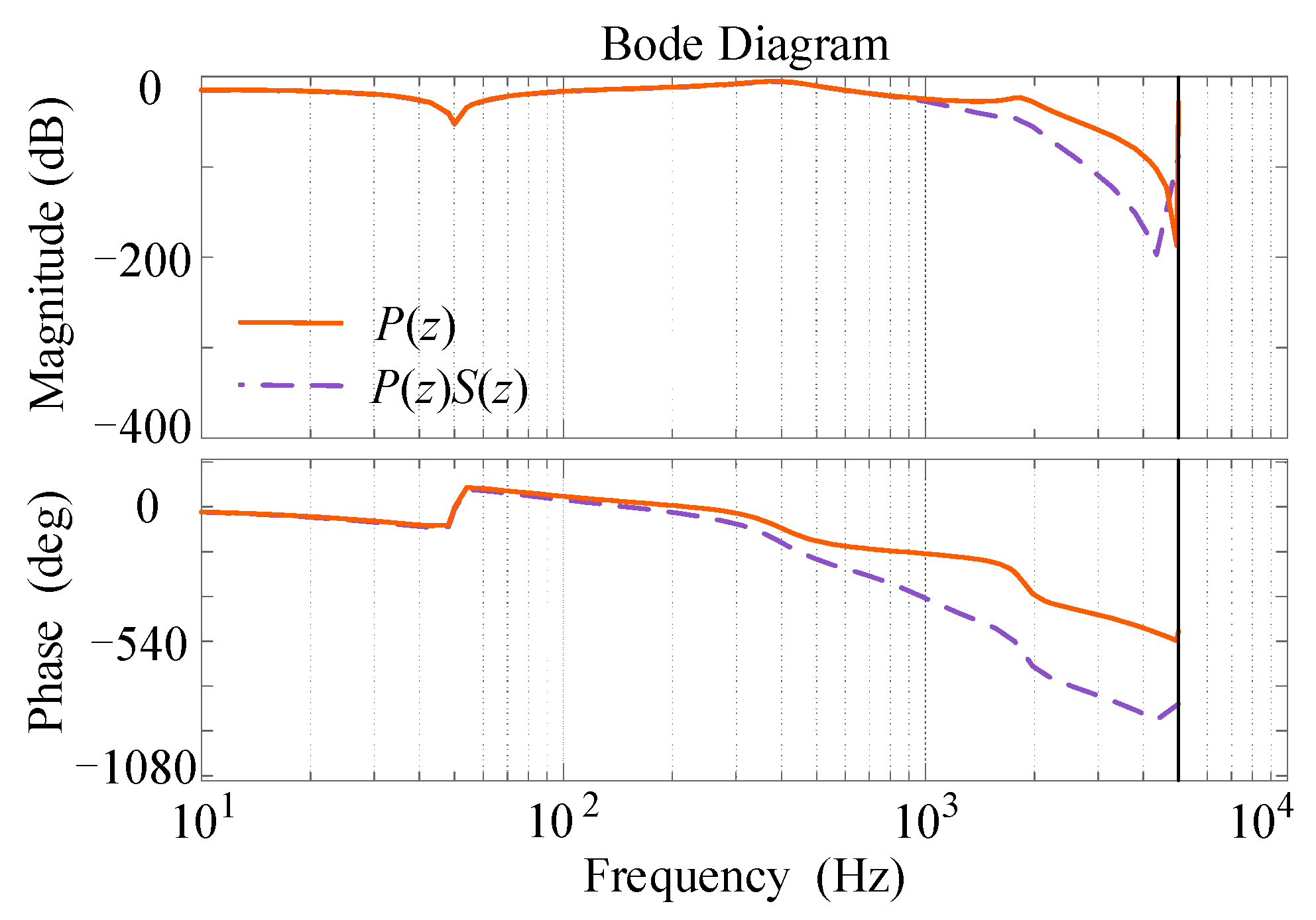
Gc is the compensator of RC. The expression is as follows:
G c ( z ) = k r z m S ( z )
where kr is the gain compensation of the system; zm is the phase lead compensation of the system; and S(z) is a filter to accelerate decay rate of high frequency band of the system.

4.3.1. Filter S(z)

In order to accelerate the attenuation of the high-frequency band of P(z), a fourth-order Butterworth filter is designed by the Filter Designer of MATLAB, and the cut-off frequency of filter is 1 kHz. The transfer function is as follows:
S ( z ) = 0.00482 z 4 + 0.0193 z 3 + 0.02895 z 2 + 0.0193 z + 0.00482 z 4 2.36951 z 3 + 2.314 z 2 1.05467 z + 0.18738
Figure 7 shows that with the introducing of Butterworth filter, the gain of P(z) in high-frequency band will be further decreased, which means a more efficient suppression is achieved of harmonics with frequency higher than 1000 kHz. However, the phase lag is more serious at the same time.

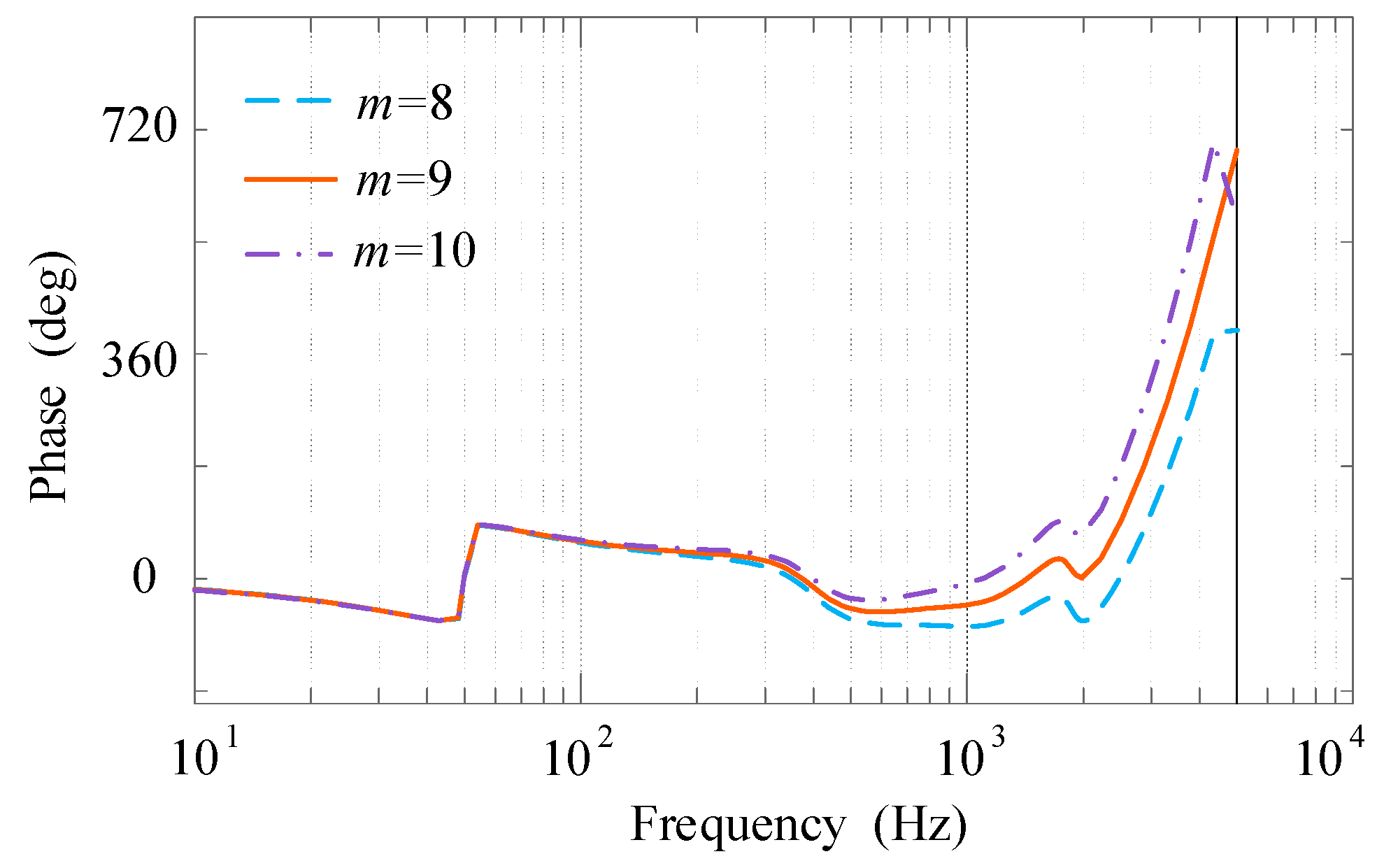
4.3.2. Phase Compensator zm
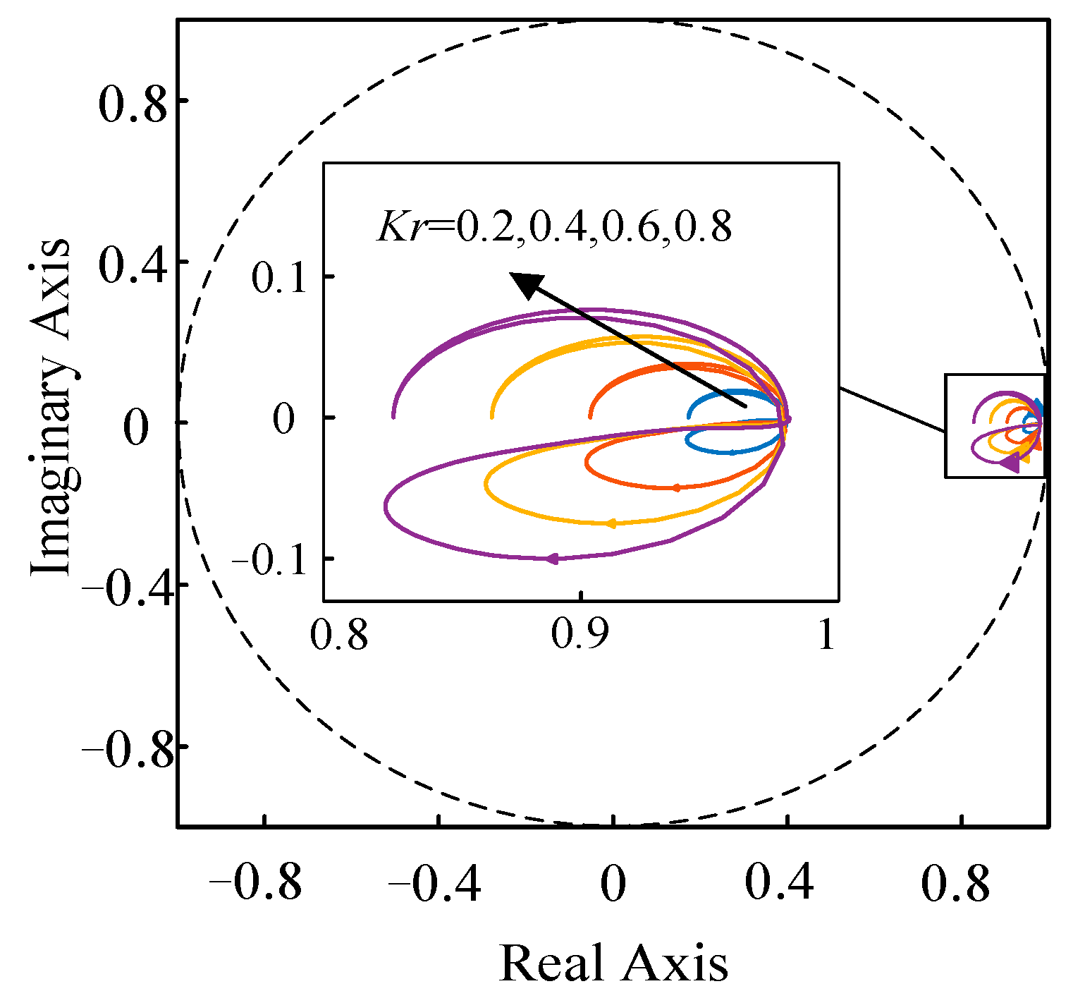
In order to compensate the phase lag induced by P(z) and S(z), a zm is introduced in Gc(z). Figure 8 shows the phase frequency characteristic of zmS(z)P(z) with different m values. It can be seen that when m equals 9, the system phase is closer to 0° and the compensation effect is the optimal, therefore, m is set to 9 in this paper.

4.3.3. The Gain kr

The gain kr is usually taken as a constant less than 1 to adjust the compensation intensity of RC. According to (17), in the whole process of ω increasing from zero frequency to Nyquist frequency (1/2 sampling frequency), the stability of the control system can be guaranteed if the trajectory of G ( e j ω T s ) does not exceed the unit circle. Figure 9 shows the trajectory of G F ( e j ω T s ) when kr changes from 0.2 to 0.8.
In general, kr is smaller than 1 [33] and because the value of kr is inversely proportional to the system stability and is directly proportional to the compensation accuracy, kr is taken as 0.6 in this paper.

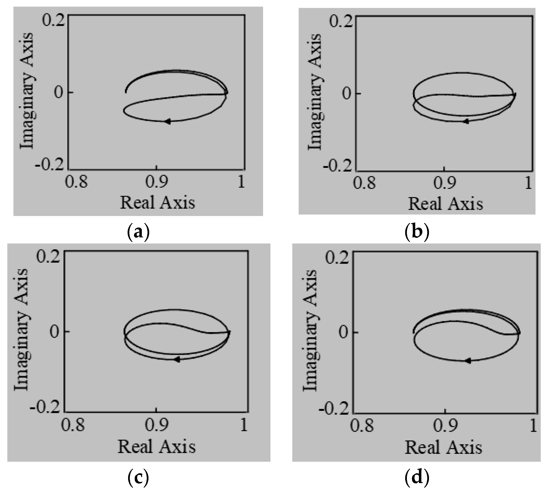
5. Stability Analysis of FAPRRC

The feedback branch of Figure 4 can be written as z N i z d ^ Q ( z ) . Thus, when the proposed Newton FD filter is adopted, the transfer function of Figure 4 GFARC can be expressed by (22):
G F A R C ( z ) = z N 1 z N i z d ^ Q ( z ) G c ( z ) = z N 1 z N i z d ^ Q ( z ) k r z m S ( z )
Based on (22), the Q(z) in (18) adds a coefficient z N i z d ^ . Replace z with ejwTs and combine it with (18) to obtain the stability condition of FAPRRC:
| G F ( e j ω T s ) | = | e j ω [ N i + d ^ ] T s Q ( e j ω T s ) k r e j ω ( N m ) T s S ( e j ω T s ) P ( e j ω T s ) | < 1 , ω [ 0 , π / T s ]
Since d ^ is very small comparing to N and N i is close to N, according to (19), (24) can be obtained:
{ | e j ω [ N i + d ^ ] T s | | e j ω N T s | = 1 | e j ω [ N m ] T s | | e j ω m T s |
According to (23) and (24), the stability conditions of FAPRRC and PRRC are the same, i.e., the trajectory of G F ( e j ω T s ) is inside the unit circle.
In the following analysis, the resistance of weak grid is neglected because it benefits to system stability. Therefore, the grid impedance can be represented by a inductances Lg and the grid-side inductance L2 of LCL filter is (L2 + Lg). Presently, power systems with short-circuit ratio (SCR) less than 10 are often regarded as weak grids [34]. In this paper, SCR is 10 corresponds to Lg is 2.5 mH.
Figure 10a–d shows the trajectory of G F ( e j ω T s ) when Lg is 0 mH, 1 mH, 3 mH and 5 mH respectively. It can be seen that even when Lg is as large as 5 mH, which corresponds to SCR = 5, the trajectory of G F ( e j ω T s ) is still inside the unit circle and the system keeps stable.

6. Simulation and Experiment

In order to verify the effectiveness of the proposed Newton-FAPRRC scheme, the simulation was carried out under Matlab/Simulink and the corresponding experimental platform was also built in our laboratory.

6.1. Simulation

In order to verify the effectiveness of the proposed Newton-FAPRRC scheme for LCL-type inverter tied with weak grid, simulations of three cases were carried out: (1) adaptability of Newton-FAPRRC under weak grid condition; (2) verification of Newton-FAPRRC dynamic performance; (3) verification of Newton-FAPRRC frequency adaptability.

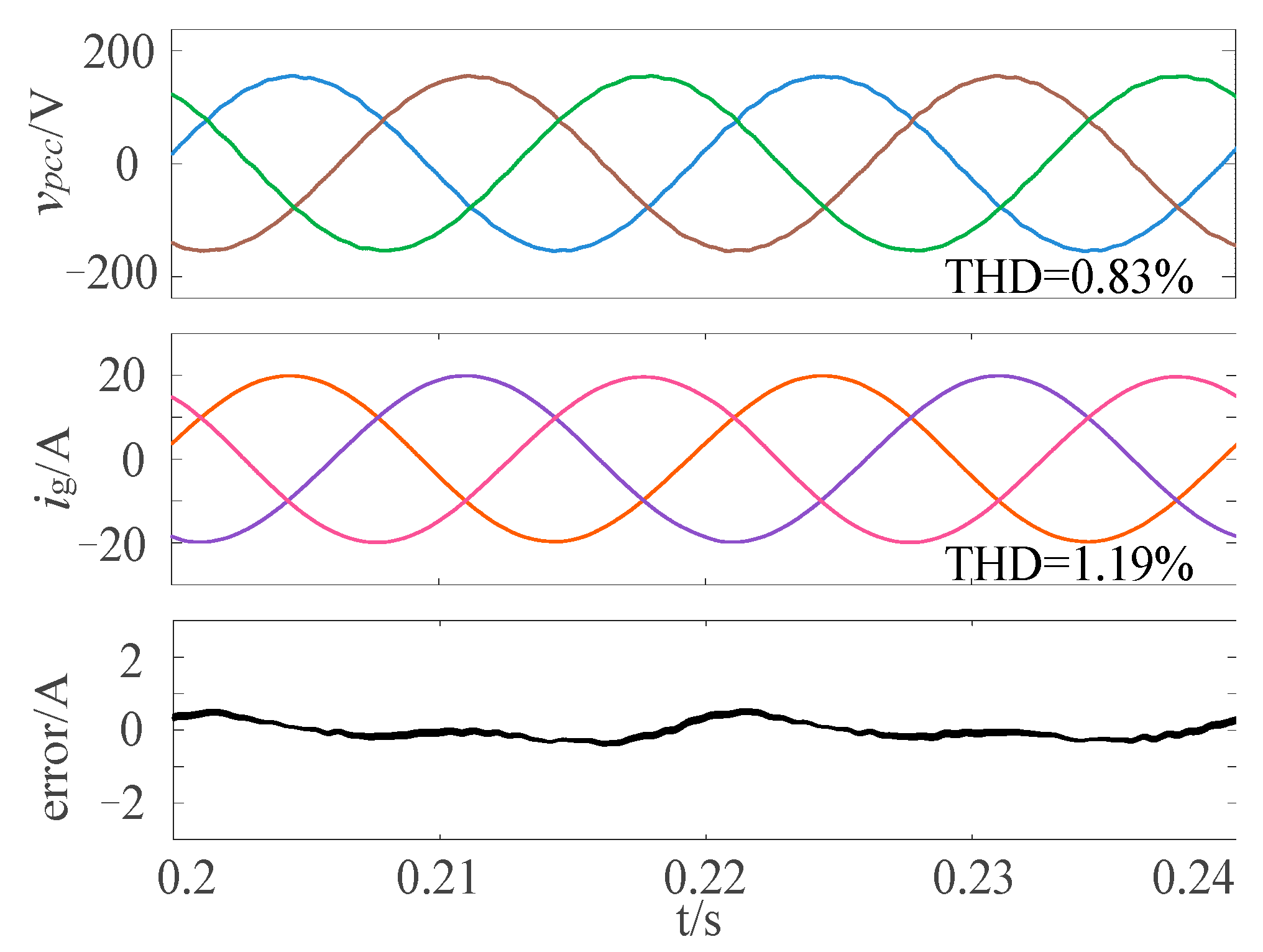
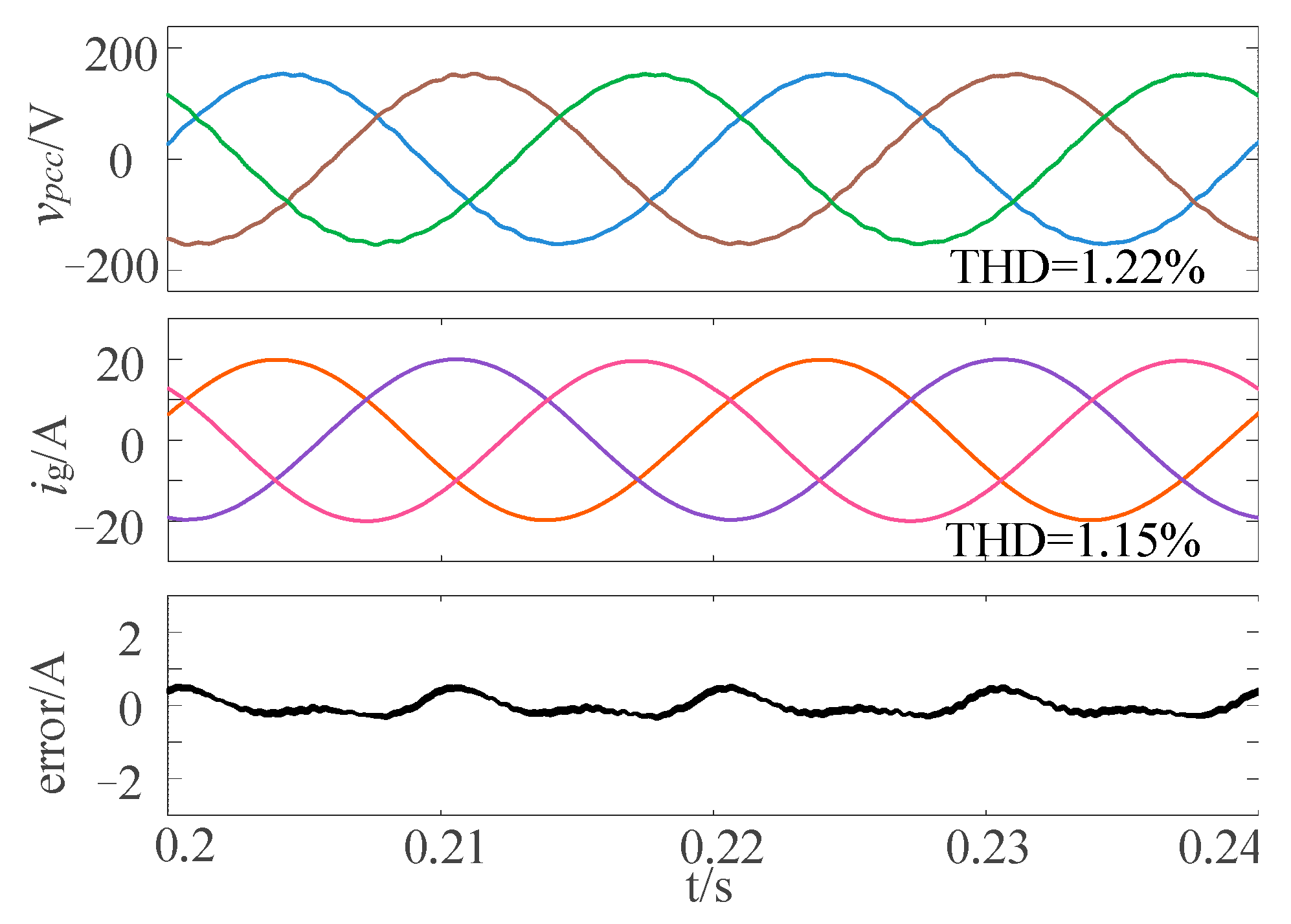
6.1.1. Adaptability of Newton FAPRRC under Weak Grid

Simulation was carried out when Lg is 0, 3 and 5 mH, respectively, and parameters used are listed as in Table 1 of the Section 4.
Figure 11, Figure 12 and Figure 13 indicate that harmonic of the voltage at the PCC vpcc increased significantly with the increasing of Lg and its THD rises from 0.83% at 3 mH to 1.22% at 5 mH. The grid current ig has the opposite trend with vpcc. When grid inductance was 0 mH, 3 mH and 5 mH, the THD of ig was 1.43%, 1.19% and 1.15%, respectively, which means that a larger Lg has a better filter effect of grid-current harmonics. Figure 13, Figure 14 and Figure 15 also show the current tracking error ε = i r e f i g ; it can be seen that ε decreases when the Lg increases.

6.1.2. Newton FAPRRC Dynamic Performance

Figure 14 shows the dynamic response of the system when the grid current reference signal iref is set to jump from 14 A to 10.5 A at 0.4 s. It can be seen that even with the large jump of the command, the proposed FAPRRC can accurately track the reference signal and the transition time is as short as about 5 ms.

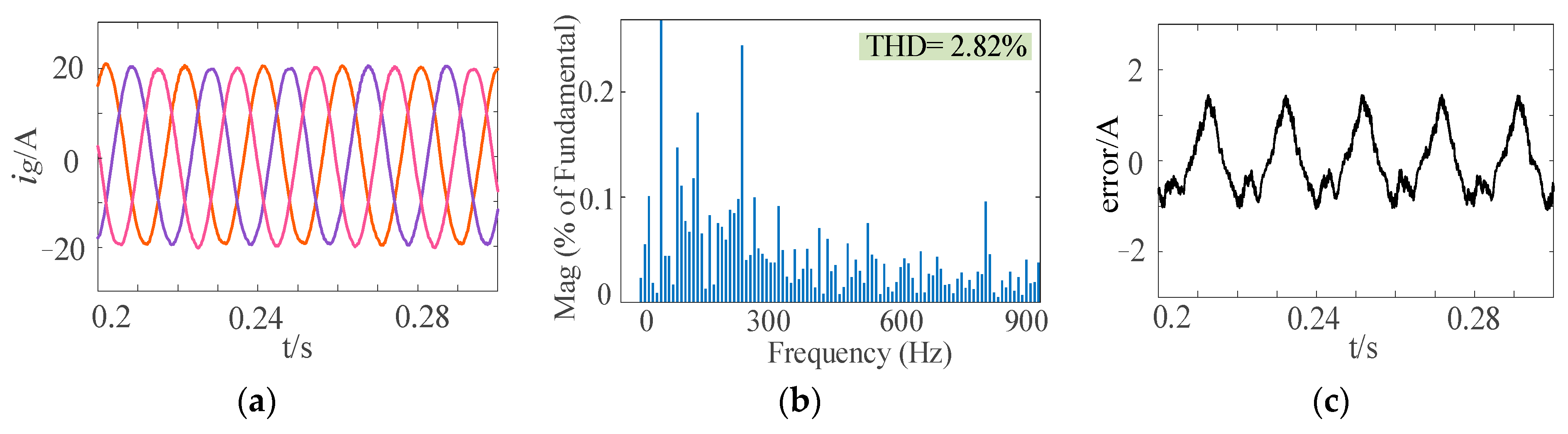
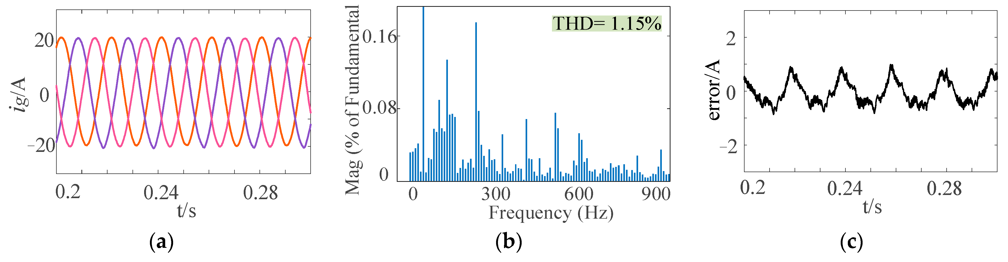
6.1.3. Verification of Newton-FAPRRC Frequency Adaptability

To verify the effectiveness of the proposed Newton-FAPRRC, frequency adaptabilities of CPRRC, Farrow-FAPRRC and Newton-FAPRRC are compared. Figure 15, Figure 16 and Figure 17 shows the simulation results of the three schemes when grid frequency is 50.8 Hz, where Figure 15, Figure 16 and Figure 17a shows the steady-state responses of ig, Figure 15, Figure 16 and Figure 17b shows the current tracking error ε and Figure 15, Figure 16 and Figure 17c shows the harmonic spectrum of grid current phase C ig_c.
According to Figure 15, Figure 16 and Figure 17, for CPRRC, the THD reaches 2.82% and the maximum ε approaches 1.5 A. The steady-state responses of Farrow-FAPRRC and Newton-FOPRRC are similar. The THD of ig_c is 1.15% and 1.16%, respectively. At the same time, the ε is greatly reduced and the maximum ε is less than 1 A. Figure 15, Figure 16 and Figure 17 indicate that FAPRRC still has high tracking accuracy even when grid frequency fluctuates, and the quality of ig is significantly improved compared to CPRRC.
More detailed simulation results at different grid frequencies are given in Table 2. It should be noted that although both Newton and Farrow structure filters have the advantages of constant coefficients and high quality of ig, the proposed Newton FD filter has simpler constructure and is easier to realize, which significantly reduces the computational burden [31] compared to the Farrow FD filter which compromises M sub-filters.

6.2. Experiment

A downscale experiment was held to verify above research. Figure 18 is the experimental platform of three-phase grid-connected LCL inverter. In the experiment, vpcc and ig were reduced to one-third of the simulated value, and other parameters remained unchanged.
Similar to simulation, the experiment was also carried out with three scenes: (1) adaptability of FAPRRC under weak grid condition; (2) verification of Newton-FAPRRC dynamic performance; (3) verification of Newton-FAPRRC frequency adaptability.

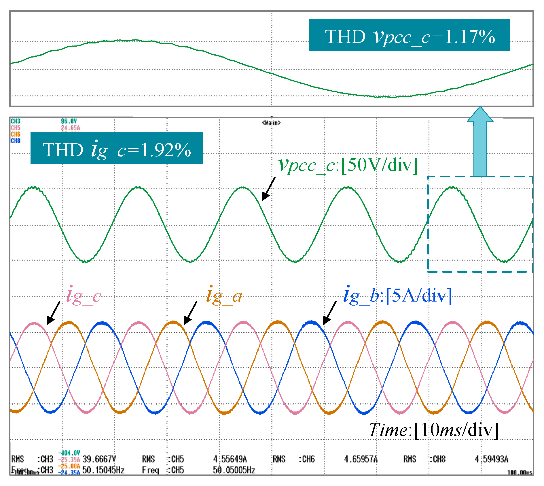
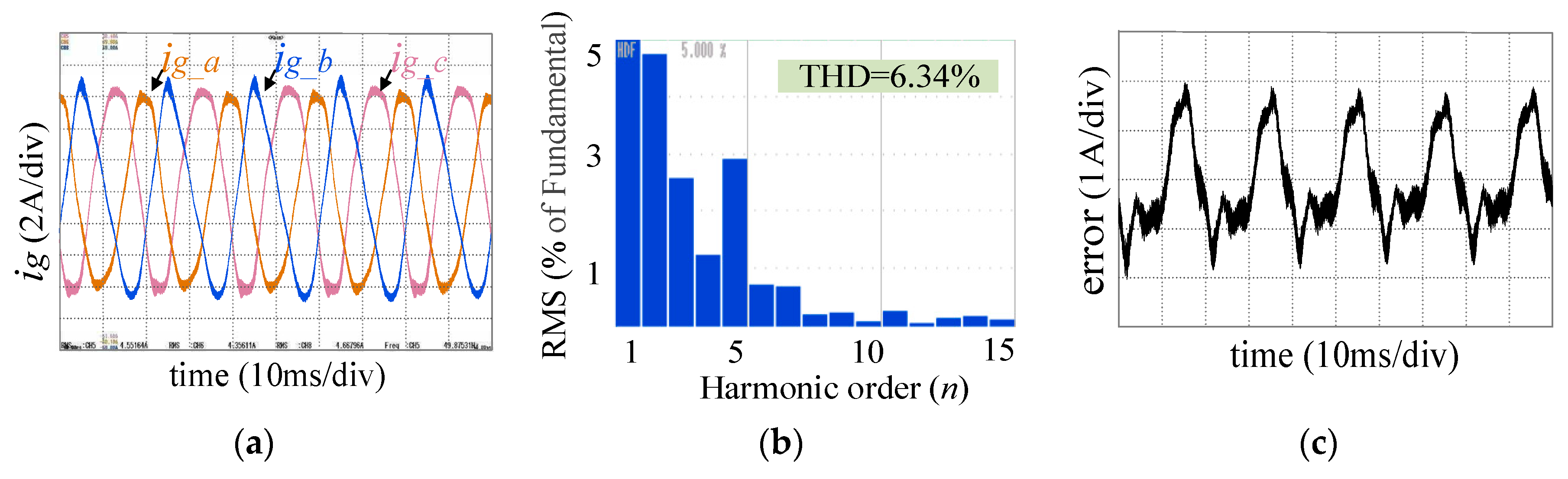
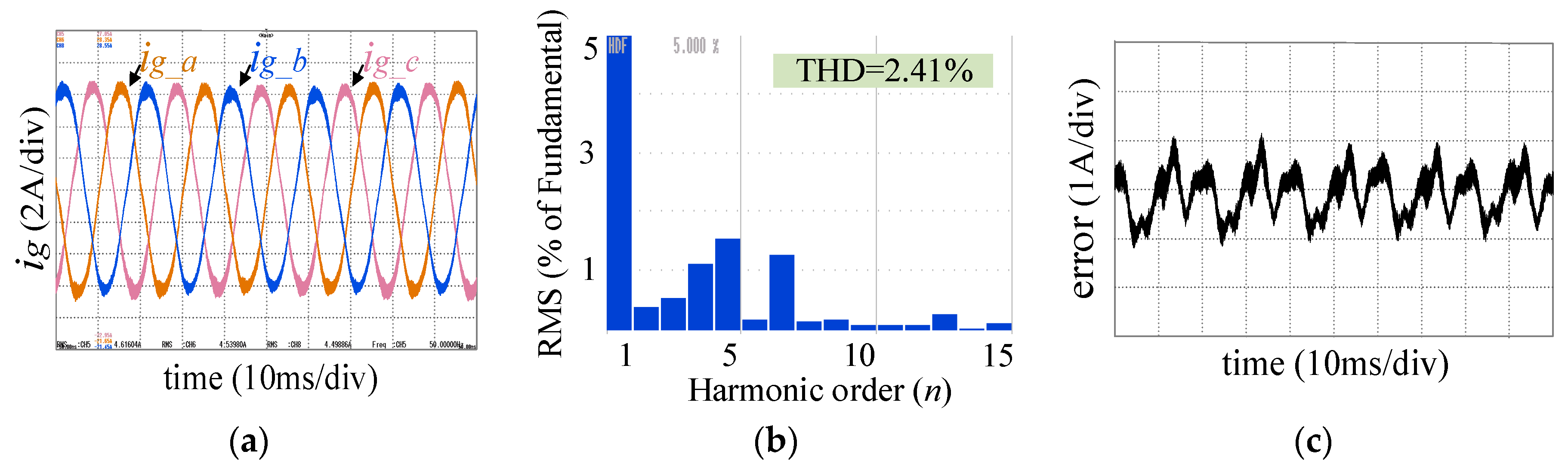
6.2.1. Adaptability of Newton FAPRRC under Weak Grid Condition

In experiments, Lg was also set to 0 mH, 3 mH and 5 mH respectively. The corresponding steady-state responses, including voltage at PCC of phase C, vpcc_c and ig, are shown in Figure 19, Figure 20 and Figure 21.
It can be seen that with the increase of Lg, the harmonic of vpcc_c also increases. The THD of vpcc_c is 0.72%, 0.95% and 1.17% when Lg is 0 mH, 3 mH and 5 mH, respectively. However, the quality of ig has a certain improvement. Figure 21 shows that even when Lg is as large as 5 mH, the system is still stable and the THD ig_c is 1.92%. It is obvious that the proposed control scheme has a relatively large stable range under weak grid condition.

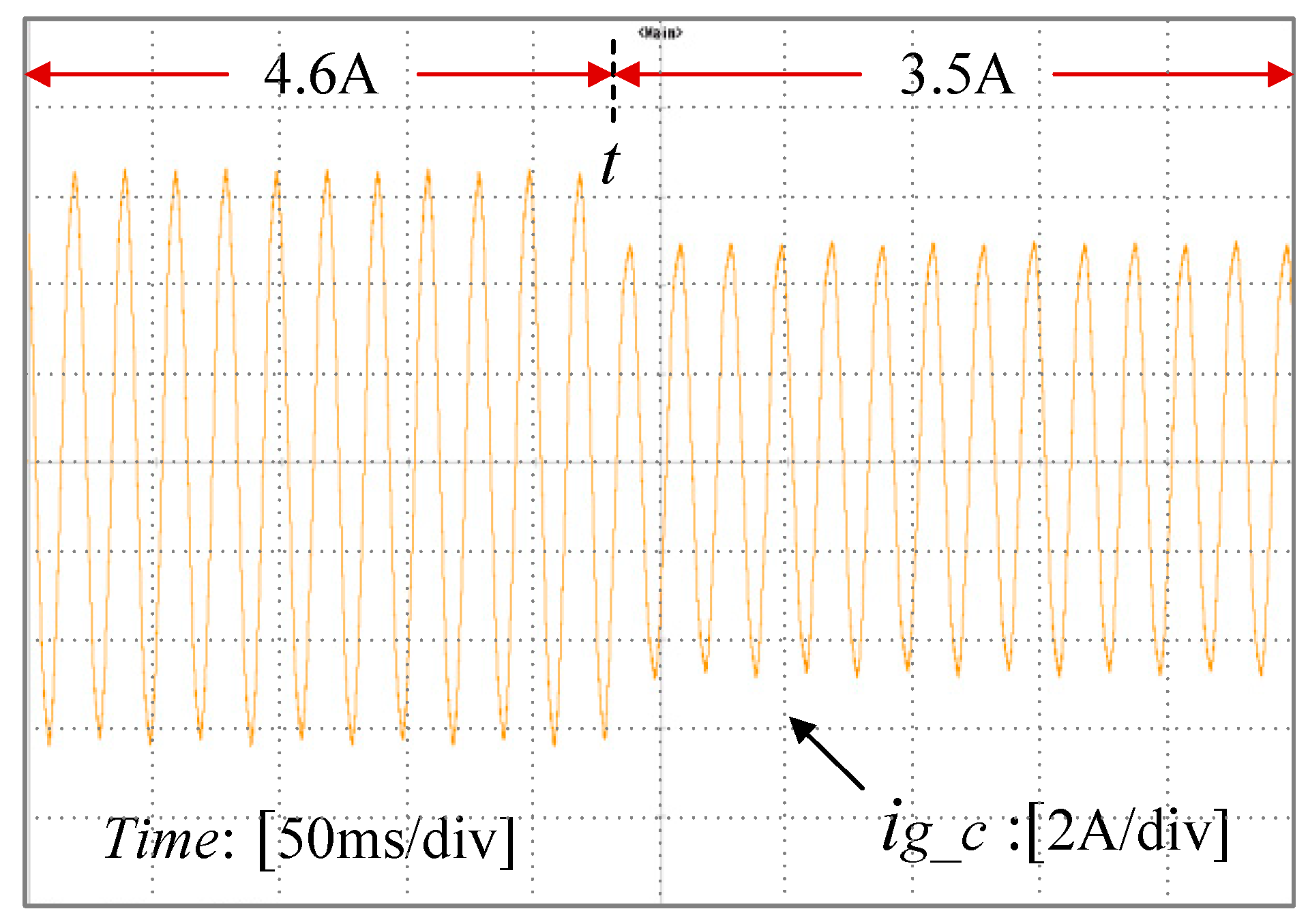
6.2.2. Verification of Newton-FAPRRC Dynamic Performance

In the experiment, the reference value of grid-current iref was operated to jump from 4.6 A to 3.5 A at time t and the transient rate achieves as 24%. The dynamic response is shown in Figure 22. It can be concluded that ig can track the reference value iref effectively and appears perfect dynamic performance.

6.2.3. Verification of Newton-FAPRRC Frequency Adaptability

Because the grid frequency cannot be adjusted in our lab, the variable grid frequency was simulated by changing the sampling frequency in experiment. To correspond to grid frequency 50.8, the sampling frequency was set to 9920 Hz. It should be noted that the little mismatch between simulated and measured results for harmonic spectrums and THD was caused by the influence of the solver and the harmonic spectrum acquisition algorithm of Matlab/Simulink. In fact, Matlab can give a more detailed harmonic spectrum, while the oscilloscope of our laboratory superimposes many non-integer harmonic components into the closest integer harmonic components.
Experimental results of the CPRRC, Farrow-FAPRRC and Newton-FAPRR (Lg = 0) are shown in the Figure 23, Figure 24 and Figure 25 respectively. Figure 23a, Figure 24a and Figure 25a shows the steady state responses of ig; Figure 23b, Figure 24b and Figure 25b and Figure 23c, Figure 24c and Figure 25c show the harmonic spectrum of ig_c and current tracking error ε.
Figure 23, Figure 24 and Figure 25 indicate that compared with the other two FAPRRC control schemes, the harmonics of CPRRC is significantly larger and the distortion is also more serious. The THD of ig_c achieves 6.34% when CPRRC is adopted. From Figure 23c, Figure 24c, Figure 25c, ε of Newton and Farrow-FAPRRC is as small as about 1 A, but for CPRRC, it can reach about 2 A. Figure 24 and Figure 25 show that Newton-FAPRRC and Farrow-FAPRRC have similar control effect and the THD of ig is 2.41% and 2.57%, respectively.
It should be noted that although Newton-FAPRRC and Farrow-FAPRRC appear as similar control effects, the former has a relatively simple structure and is easy to realize in implementation.

7. Conclusions

In order to suppress the grid current harmonics of LCL-type inverter under weak grid condition, a frequency adaptive scheme based on Newton Structure of PRRC is proposed. Comparing to FD filter based on Lagrange interpolation and Farrow structure, Newton FD filter has the advantages of simple structure and constant coefficients even when the grid frequency fluctuates, and is applied to RC to approximate the fractional delay item z-d to improve frequency adaptability. In this paper, the detail derivation of the general Newton structure and the parameters setting of proposed FAPRRC are given. At the same time, the stability of the control system under weak grid is analyzed. The simulation and experimental results indicate that the proposed Newton-FAPRRC can improve grid current quality and appears strong adaptability under weak grid condition.

Author Contributions

Conceptualization, C.Z. and S.L.; methodology, C.Z. and S.L.; software, S.L.; validation, C.Z., S.L., H.W. and H.M.; formal analysis, S.L.; investigation, C.Z. and H.M.; resources, C.Z. and H.M.; data curation, S.L.; writing—original draft preparation, S.L.; writing—review and editing, C.Z. and H.M.; visualization, H.M.; supervision, H.M.; project administration, C.Z. and H.M.; funding acquisition, C.Z. and H.M. All authors have read and agreed to the published version of the manuscript.

Funding

This research was funded by Sichuan Science and Technology Program under Grant 2021YFG0256 and 2021YFG0218. This research was funded by Chengdu Science and Technology Program under Grant 2021-YF05-01358-SN.

Acknowledgments

This work was supported by Sichuan Science and Technology Program under Grant 2021YFG0256 and 2021YFG0218. This work was supported by Chengdu Science and Technology Program under Grant 2021-YF05-01358-SN.

Conflicts of Interest

The authors declare no conflict of interest.

References

  1. Li, X.; Fang, J.; Tang, Y.; Wu, X.; Geng, Y. Capacitor-Voltage Feedforward with Full Delay Compensation to Improve Weak Grids Adaptability of LCL-Filtered Grid-Connected Converters for Distributed Generation Systems. IEEE Trans. Power Electron. 2018, 33, 749–764. [Google Scholar] [CrossRef]
  2. Dogra, R.; Rajpurohit, B.S.; Tummuru, N.R.; Marinova, I.; Mateev, V. Superimposed Component based Fault Detection Scheme for Multi-port DC Microgrid. In Proceedings of the 2020 IEEE International Conference on Power Electronics, Drives and Energy Systems (PEDES), Jaipur, India, 16–19 December 2020; pp. 1–6. [Google Scholar] [CrossRef]
  3. Wang, X.; Blaabjerg, F. Harmonic Stability in Power Electronic-Based Power Systems: Concept, Modeling, and Analysis. IEEE Trans. Smart Grid 2019, 10, 2858–2870. [Google Scholar] [CrossRef] [Green Version]
  4. Yang, D.; Ruan, X.; Wu, H. Impedance Shaping of the Grid-Connected Inverter with LCL Filter to Improve Its Adaptability to the Weak Grid Condition. IEEE Trans. Power Electron. 2014, 29, 5795–5805. [Google Scholar] [CrossRef]
  5. Dannehl, J.; Wessels, C.; Fuchs, F.W. Limitations of Voltage-Oriented PI Current Control of Grid-Connected PWM Rectifiers with LCL Filters. IEEE Trans. Ind. Electron. 2009, 56, 380–388. [Google Scholar] [CrossRef]
  6. Bao, C.; Ruan, X.; Wang, X.; Li, W.; Pan, D.; Weng, K. Step-by-Step Controller Design for LCL-Type Grid-Connected Inverter with Capacitor–Current-Feedback Active-Damping. IEEE Trans. Power Electron. 2014, 29, 1239–1253. [Google Scholar] [CrossRef]
  7. Xu, J.; Xie, S.; Tang, T. Evaluations of current control in weak grid case for grid-connected LCL-filtered inverter. IET Power Electron. 2013, 6, 227–234. [Google Scholar] [CrossRef]
  8. Hu, J. Improved Dead-Beat Predictive DPC Strategy of Grid-Connected DC–AC Converters With Switching Loss Minimization and Delay Compensations. IEEE Trans. Ind. Inform. 2013, 9, 728–738. [Google Scholar] [CrossRef]
  9. Evran, F. Plug-in Repetitive Control of Single-phase Grid-connected Inverter for AC Module Applications. IET Power Electron. 2016, 10, 47–58. [Google Scholar] [CrossRef]
  10. Zhao, Q.; Ye, Y. A PIMR-Type Repetitive Control for a Grid-Tied Inverter: Structure, Analysis, and Design. IEEE Trans. Power Electron. 2018, 33, 2730–2739. [Google Scholar] [CrossRef]
  11. Trinh, Q.-N.; Choo, F.-H.; Chi, J.; Peng, W. An improved control strategy for three-phase AC/DC/AC converter in UPS application. In Proceedings of the 2016 Asian Conference on Energy, Power and Transportation Electrification (ACEPT), Singapore, 25–27 October 2016; pp. 1–6. [Google Scholar] [CrossRef]
  12. Kang, L.; Zhang, J.; Zhou, H.; Zhao, Z.; Duan, X. Model Predictive Current Control with Fixed Switching Frequency and Dead-Time Compensation for Single-Phase PWM Rectifier. Electronics 2021, 10, 426. [Google Scholar] [CrossRef]
  13. Yang, S.; Lei, Q.; Peng, F.Z.; Qian, Z. A Robust Control Scheme for Grid-Connected Voltage-Source Inverters. IEEE Trans. Ind. Electron. 2011, 58, 202–212. [Google Scholar] [CrossRef]
  14. Shen, G.; Zhu, X.; Zhang, J.; Xu, D. A New Feedback Method for PR Current Control of LCL-Filter-Based Grid-Connected Inverter. IEEE Trans. Ind. Electron. 2010, 57, 2033–2041. [Google Scholar] [CrossRef]
  15. Pereira, L.F.A.; Flores, J.V.; Bonan, G.; Coutinho, D.F.; Da Silva, J.M.G. Multiple Resonant Controllers for Uninterruptible Power Supplies—A Systematic Robust Control Design Approach. IEEE Trans. Ind. Electron. 2014, 61, 1528–1538. [Google Scholar] [CrossRef]
  16. Hu, J.; Zhu, Z.Q. Improved Voltage-Vector Sequences on Dead-Beat Predictive Direct Power Control of Reversible Three-Phase Grid-Connected Voltage-Source Converters. IEEE Trans. Power Electron. 2013, 28, 254–267. [Google Scholar] [CrossRef]
  17. Yang, Y.; Zhou, K.; Blaabjerg, F. Enhancing the Frequency Adaptability of Periodic Current Controllers with a Fixed Sampling Rate for Grid-Connected Power Converters. IEEE Trans. Power Electron. 2016, 31, 7273–7285. [Google Scholar] [CrossRef] [Green Version]
  18. Zimann, F.J.; Stangler, E.; Neves, F.V.; Batschauer, A.L.; Mezaroba, M. Coordinated Control of Active and Reactive Power Compensation for Voltage Regulation with Enhanced Disturbance Rejection Using Repetitive Vector-Control. Energies 2020, 13, 2812. [Google Scholar] [CrossRef]
  19. Wei, J.; Li, Y.; Sun, G.; Bu, L. H∞ Repetitive Control Based on Active Damping with Reduced Computation Delay for LCL-Type Grid-Connected Inverters. Energies 2017, 10, 586. [Google Scholar]
  20. Chen, J.; Jiang, X.; Zhu, D.; Deng, L.; Yang, B. High Power Hybrid Active Power Filter for Medium-voltage Distribution Network. In Proceedings of the 2005 International Conference on Electrical Machines and Systems, Nanjing, China, 27–29 September 2005; pp. 1381–1386. [Google Scholar]
  21. Zou, Z.-X.; Zhou, K.; Wang, Z.; Cheng, M. Frequency-Adaptive Fractional-Order Repetitive Control of Shunt Active Power Filters. IEEE Trans. Ind. Electron. 2015, 62, 1659–1668. [Google Scholar] [CrossRef]
  22. Liu, Z.; Zhang, B.; Zhou, K. Universal Fractional-Order Design of Linear Phase Lead Compensation Multirate Repetitive Control for PWM Inverters. IEEE Trans. Ind. Electron. 2017, 64, 7132–7140. [Google Scholar] [CrossRef] [Green Version]
  23. Wang, W.; Lu, W.; Zhou, K.; Fan, Q. Fractional-Order New Generation of nk ± m-Order Harmonic Repetitive Control for PWM Converters. IEEE Access 2020, 8, 180706–180721. [Google Scholar] [CrossRef]
  24. Xu, J.; Xie, S.; Tang, T. Active Damping-Based Control for Grid-Connected LCL-Filtered Inverter with Injected Grid Current Feedback Only. IEEE Trans. Ind. Electron. 2014, 61, 4746–4758. [Google Scholar] [CrossRef]
  25. Cui, P.; Zhang, G.; Liu, Z.; Han, B.; Wang, Q. A Second-Order Dual Mode Repetitive Control for Magnetically Suspended Rotor. IEEE Trans. Ind. Electron. 2020, 67, 4946–4956. [Google Scholar] [CrossRef]
  26. Tian, B.; Sun, L.; Molinas, M.; An, Q.-T. Repetitive Control Based Phase Voltage Modulation Amendment for FOC-Based Five-Phase PMSMs Under Single-Phase Open Fault. IEEE Trans. Ind. Electron. 2021, 68, 1949–1960. [Google Scholar] [CrossRef]
  27. Yang, Y.; Zhou, K.; Wang, H.; Blaabjerg, F.; Wang, D.; Zhang, B. Frequency Adaptive Selective Harmonic Control for Grid-Connected Inverters. IEEE Trans. Power Electron. 2015, 30, 3912–3924. [Google Scholar] [CrossRef] [Green Version]
  28. Zeineddine, A.; Paquelet, S.; Nafkha, A.; Moy, C.; Jezequel, P.-Y. Generalization and Coefficients Optimization of the Newton Structure. In Proceedings of the 2018 25th International Conference on Telecommunications (ICT), Saint-Malo, France, 26–28 June 2018; pp. 98–103. [Google Scholar]
  29. Lamb, D.; Chamon, L.; Nascimento, V.H. Efficient filtering structure for spline interpolation and decimation. Electron. Lett. 2016, 52, 39–41. [Google Scholar] [CrossRef] [Green Version]
  30. Zeineddine, A.; Nafkha, A.; Moy, C.; Paquelet, S.; Jezequel, P.-Y. Variable Fractional Delay Filter: A Novel Architecture Based on Hermite Interpolation. In Proceedings of the 2018 25th International Conference on Telecommunications (ICT), Saint-Malo, France, 26–28 June 2018; pp. 93–97. [Google Scholar]
  31. Zeineddine, A.; Nafkha, A.; Paquelet, S.; Moy, C.; Jezequel, P.Y. Comprehensive Survey of FIR-Based Sample Rate Conversion. J. Signal Process. Syst. 2020, 93, 113–125. [Google Scholar] [CrossRef]
  32. Zou, Z.; Wang, Z.; Cheng, M. Modeling, Analysis, and Design of Multifunction Grid-Interfaced Inverters With Output LCL Filter. IEEE Trans. Power Electron. 2014, 29, 3830–3839. [Google Scholar] [CrossRef]
  33. Zhao, Q.; Ye, Y. Fractional Phase Lead Compensation RC for an Inverter: Analysis, Design, and Verification. IEEE Trans. Ind. Electron. 2017, 64, 3127–3136. [Google Scholar] [CrossRef]
  34. Xu, J.; Qian, Q.; Zhang, B.; Xie, S. Harmonics and Stability Analysis of Single-Phase Grid-Connected Inverters in Distributed Power Generation Systems Considering Phase-Locked Loop Impact. IEEE Trans. Sustain. Energy 2019, 10, 1470–1480. [Google Scholar] [CrossRef]
Figure 1. Structure and control scheme of grid-connected LCL inverter.
Energies 14 04225 g001
Figure 2. Control structure diagram of grid-connected LCL inverter.
Energies 14 04225 g002
Figure 3. Control structure diagram of grid-connected LCL inverter in z domain.
Energies 14 04225 g003
Figure 4. Schematic diagram of Newton FD filter applied to FARC.
Energies 14 04225 g004
Figure 5. Structure of third-order Newton FD filter.
Energies 14 04225 g005
Figure 6. Amplitude frequency characteristics of CPRRC and Newton-FAPRRC.
Energies 14 04225 g006
Figure 7. Phase frequency characteristics of P(z) and P(z)S(z).
Energies 14 04225 g007
Figure 8. Phase frequency characteristic of zmS(z)P(z).
Energies 14 04225 g008
Figure 9. Trajectory of GF (ejwTs) with different kr.
Energies 14 04225 g009
Figure 10. Trajectory of GF (ejwTs) with different Lg. (a) Lg = 0mH. (b) Lg = 1mH. (c) Lg = 3mH. (d) Lg = 5mH.
Energies 14 04225 g010
Figure 11. Steady-state responses when Lg is 0 mH.
Energies 14 04225 g011
Figure 12. Steady-state responses when Lg is 3 mH.
Energies 14 04225 g012
Figure 13. Steady-state responses when Lg is 5 mH.
Energies 14 04225 g013
Figure 14. Dynamic response of ig of phase C.
Energies 14 04225 g014
Figure 15. Simulation results of CPRRC at 50.8 Hz: (a) Grid current ig. (b) Harmonic spectrum of ig_c. (c) Current tracking error ɛ.
Energies 14 04225 g015
Figure 16. Simulation results of Farrow-FOPRRC at 50.8 Hz: (a) Grid current ig. (b) Harmonic spectrum of ig_c. (c) Current tracking error ɛ.
Energies 14 04225 g016
Figure 17. Simulation results of Newton-FOPRRC at 50.8 Hz: (a) Grid current ig. (b) Harmonic spectrum of ig_c. (c) Current tracking error ɛ.
Energies 14 04225 g017
Figure 18. Experimental platform of three-phase grid-connected inverter.
Energies 14 04225 g018
Figure 19. Steady-state responses when Lg is 0 mH.
Energies 14 04225 g019
Figure 20. Steady-state responses when Lg is 3 mH.
Energies 14 04225 g020
Figure 21. Steady-state responses when Lg is 5 mH.
Energies 14 04225 g021
Figure 22. Experimental results of the dynamic response with iref mutation.
Energies 14 04225 g022
Figure 23. Experimental results of CPRRC with variable grid frequency. (a) Grid current ig. (b) Harmonic spectrum of ig_c. (c) Current tracking error ɛ.
Energies 14 04225 g023
Figure 24. Experimental results of Farrow-FOPRRC with variable grid frequency. (a) Grid current ig. (b) Harmonic spectrum of ig_c. (c) Current tracking error ɛ.
Energies 14 04225 g024
Figure 25. Experimental results of Newton-FOPRRC with variable grid frequency. (a) Grid current ig. (b) Harmonic spectrum of ig_c. (c) Current tracking error ɛ.
Energies 14 04225 g025
Table 1. Parameters of LCL-type inverter and controller.
ParameterSymbolValue
Rated powerP9.1 kW
Grid voltagevg110 V
Grid-side inductorL21 mH
Inverter-side inductorL13 mH
Capacitor of LCL-filterC10 uF
DC voltageVDC200 V
Frequencyf50 Hz
Sampling frequencyfs10 kHz
Switching frequencyfsw10 kHz
Feedback coefficient of GCFADkc30
Cut-off frequency of GCFADωc12,165
Proportional gain of PRkp5
Integral gain of PRki2500
Bandwidth coefficient of PRωi3.14
Table 2. The THD of grid-current ig with different grid frequencies.
Frequency/HzCPRRCFarrowNewton
iaibiciaibiciaibic
49.22.73%2.89%2.77%1.15%1.18%1.21%1.11%1.17%1.19%
49.61.87%1.95%1.85%1.07%1.06%1.13%1.08%1.11%1.06%
501.35%1.37%1.33%1.35%1.35%1.38%1.34%1.35%1.36%
50.41.88%1.96%1.78%1.17%1.20%1.22%1.13%1.19%1.20%
50.82.82%3.00%2.83%1.15%1.14%1.18%1.16%1.18%1.16%
Publisher’s Note: MDPI stays neutral with regard to jurisdictional claims in published maps and institutional affiliations.

