
Effects of Tip Speed Ratios on the Blade Forces of a Small H-Darrieus Wind Turbine


Abstract
:1. Introduction
2. Methods of Numerical Simulation and Experimental Measurements
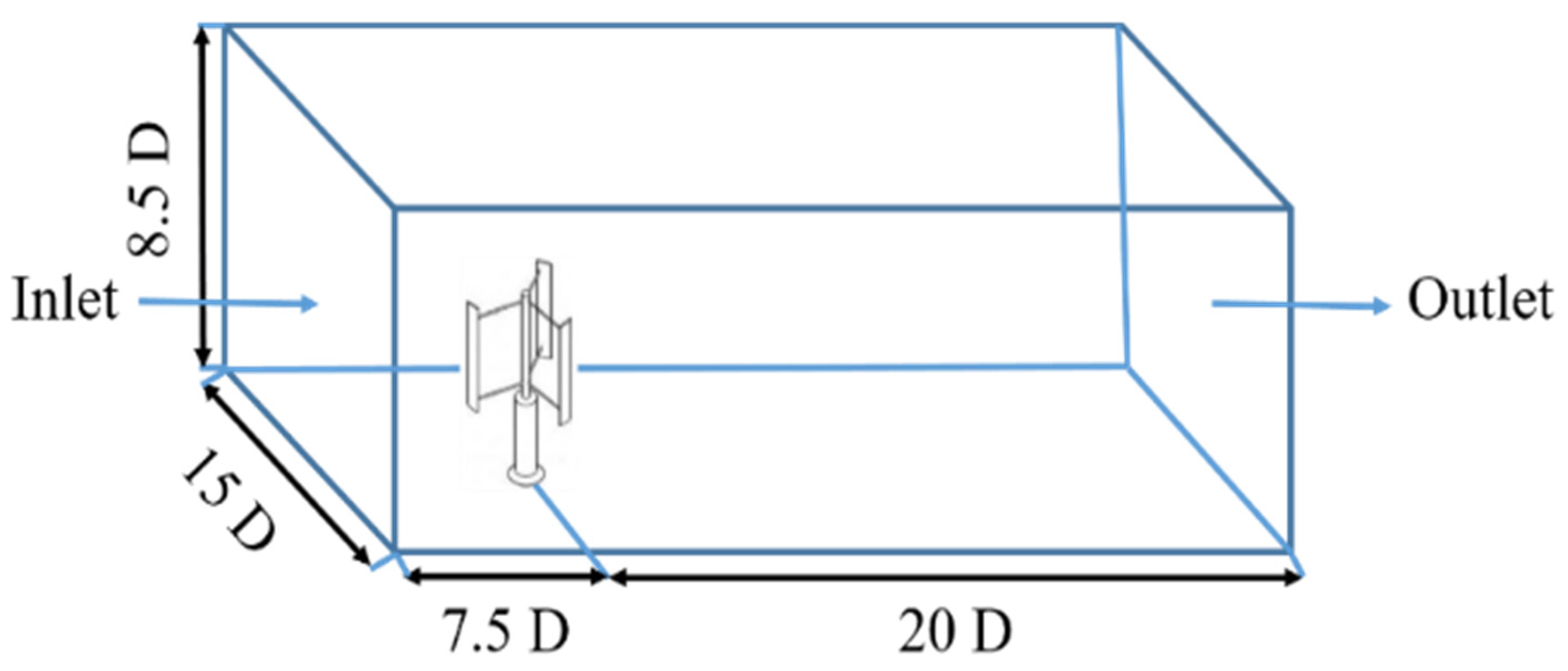
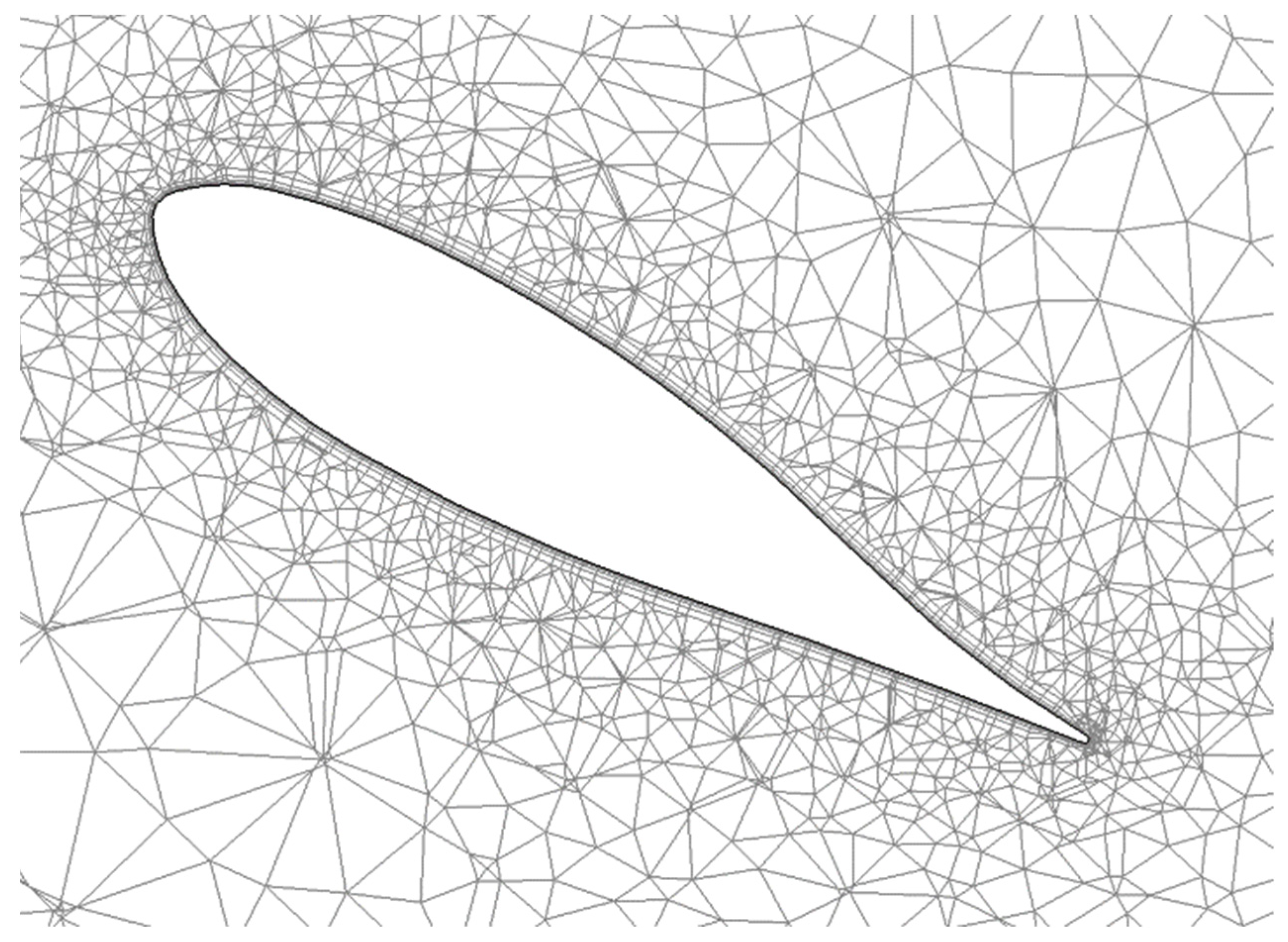
2.1. Numerical Methods
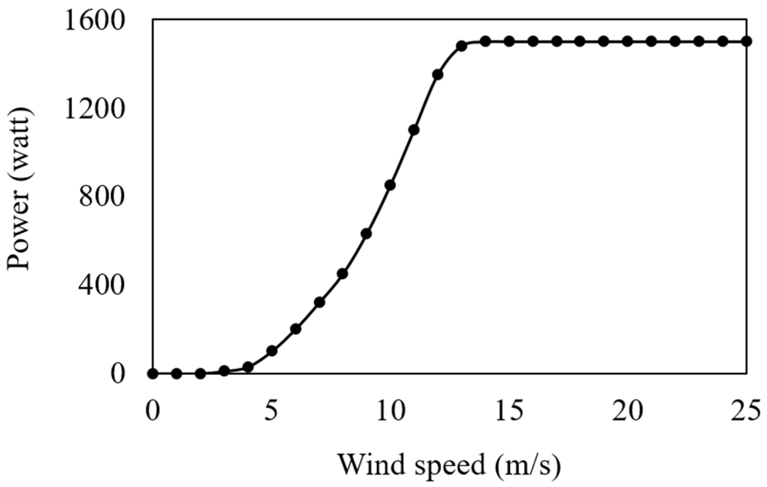
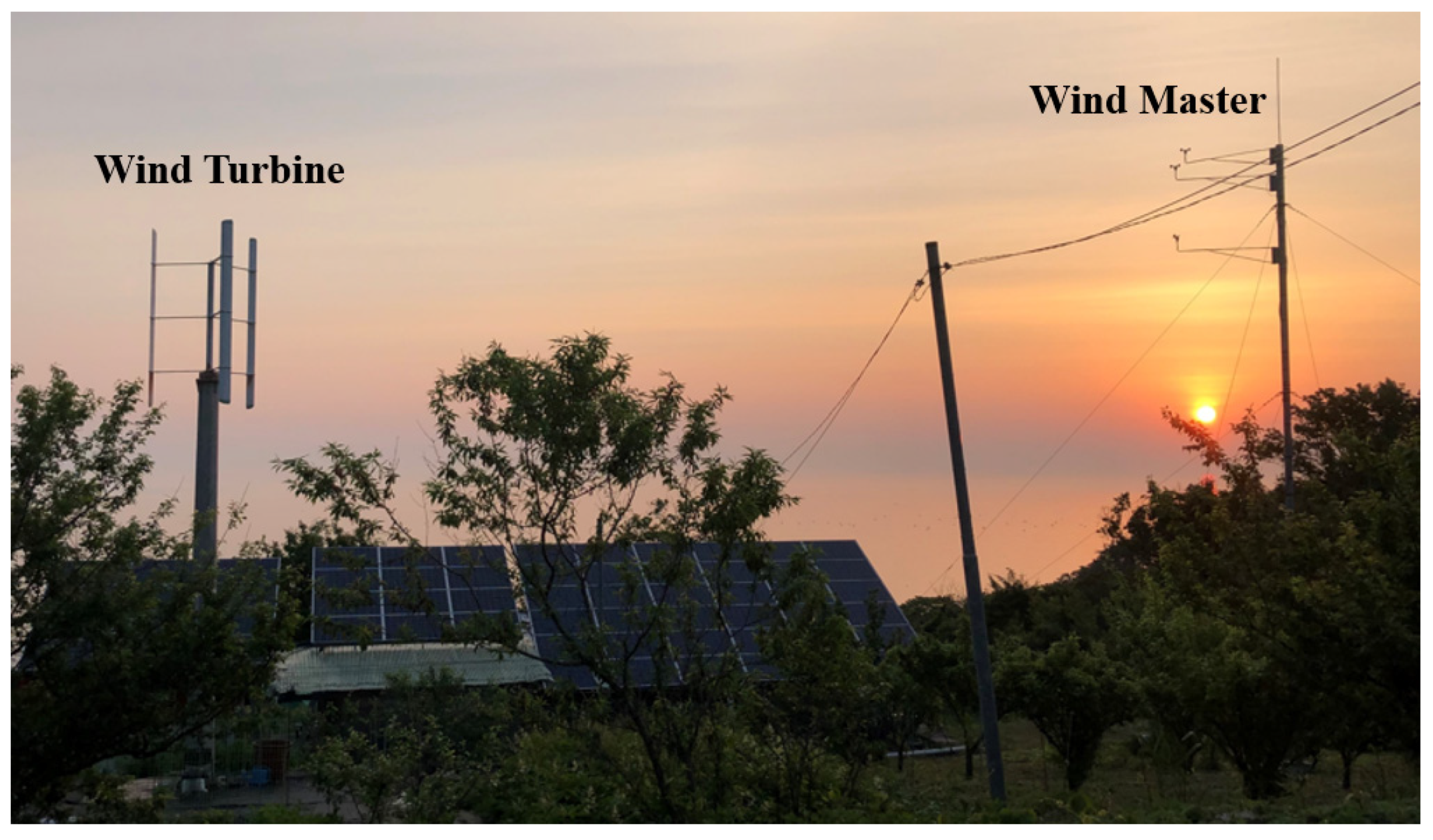
2.2. Experimental Method of a Darrieus Wind Turbine
3. Results and Discussion
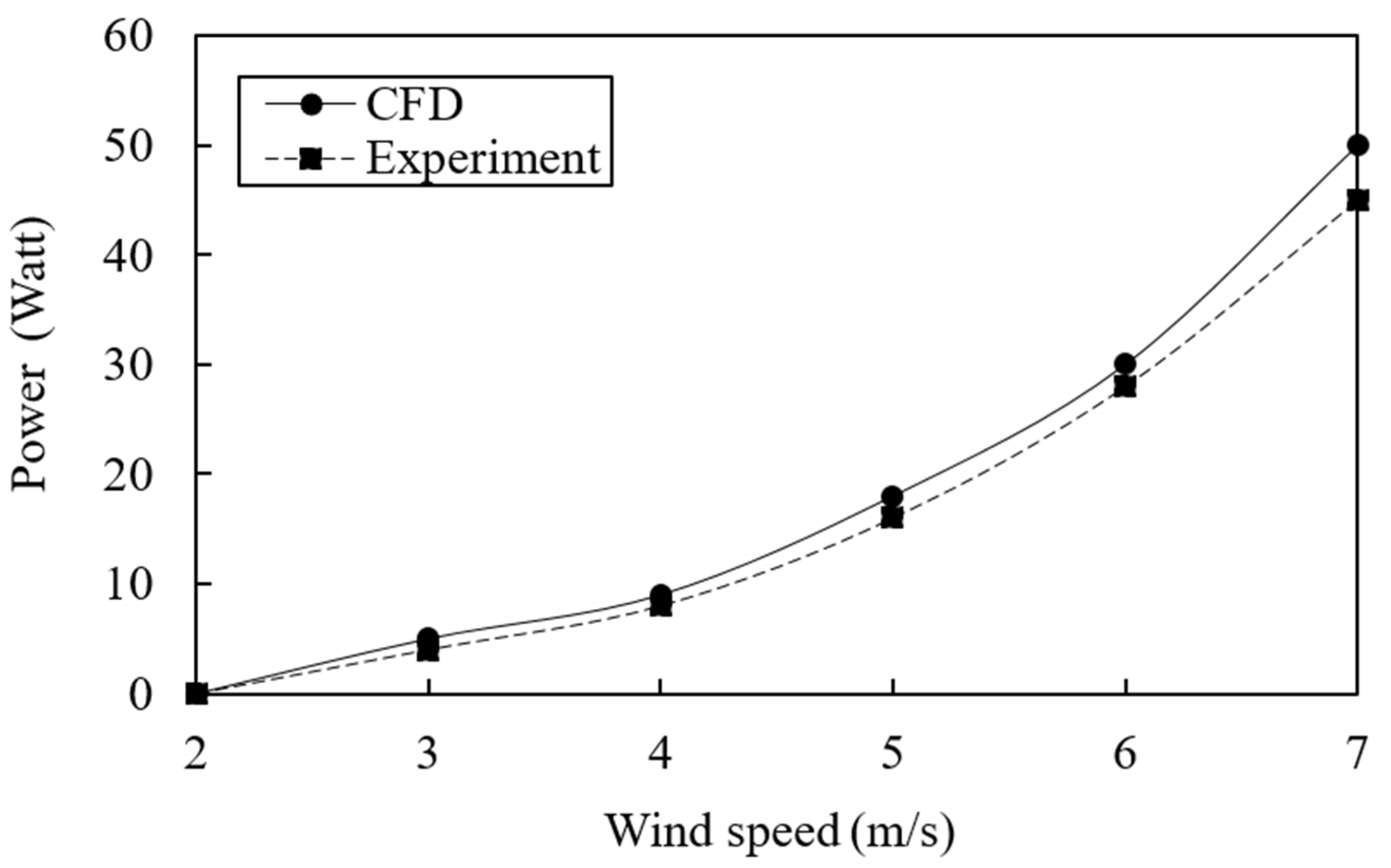
3.1. Validation of Numerical Model with Experimental Data
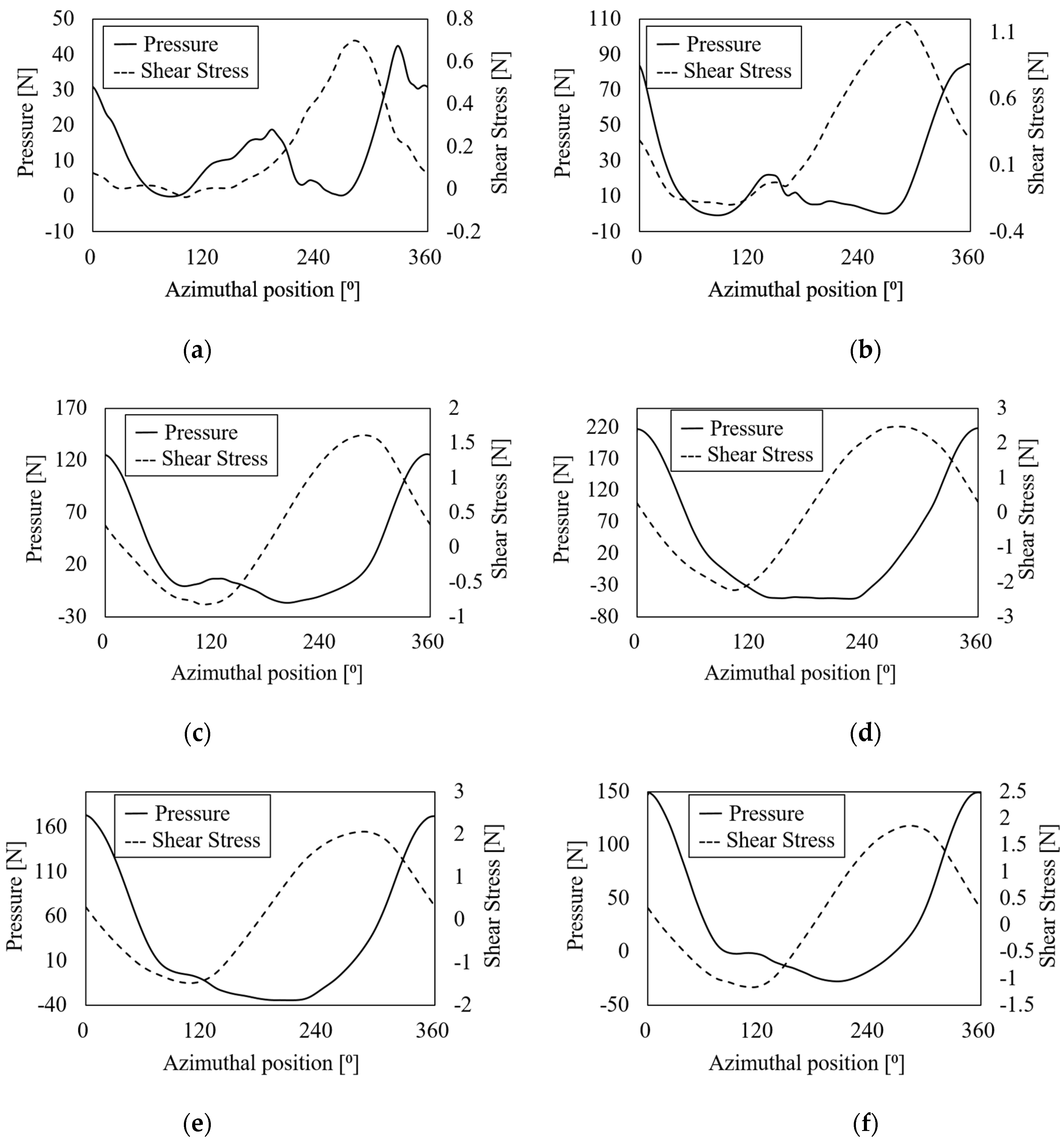
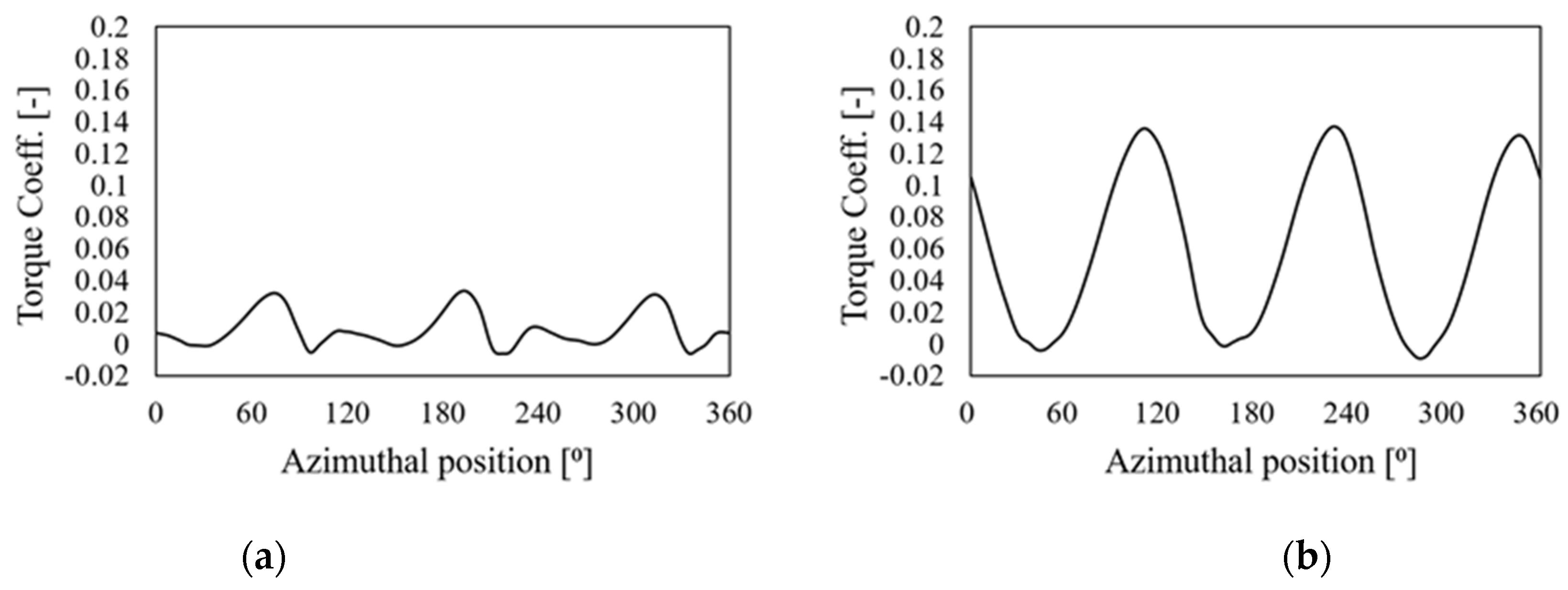
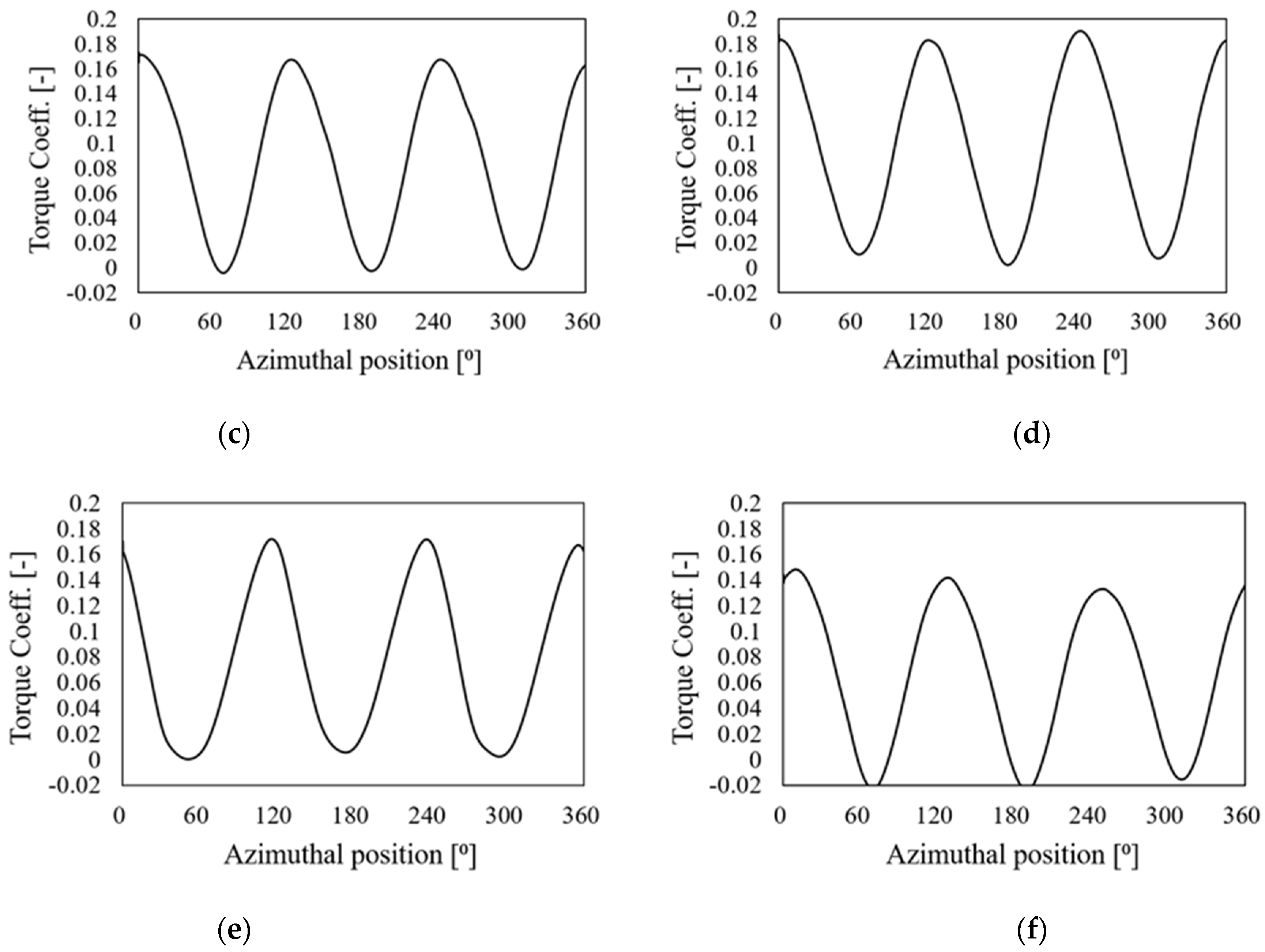
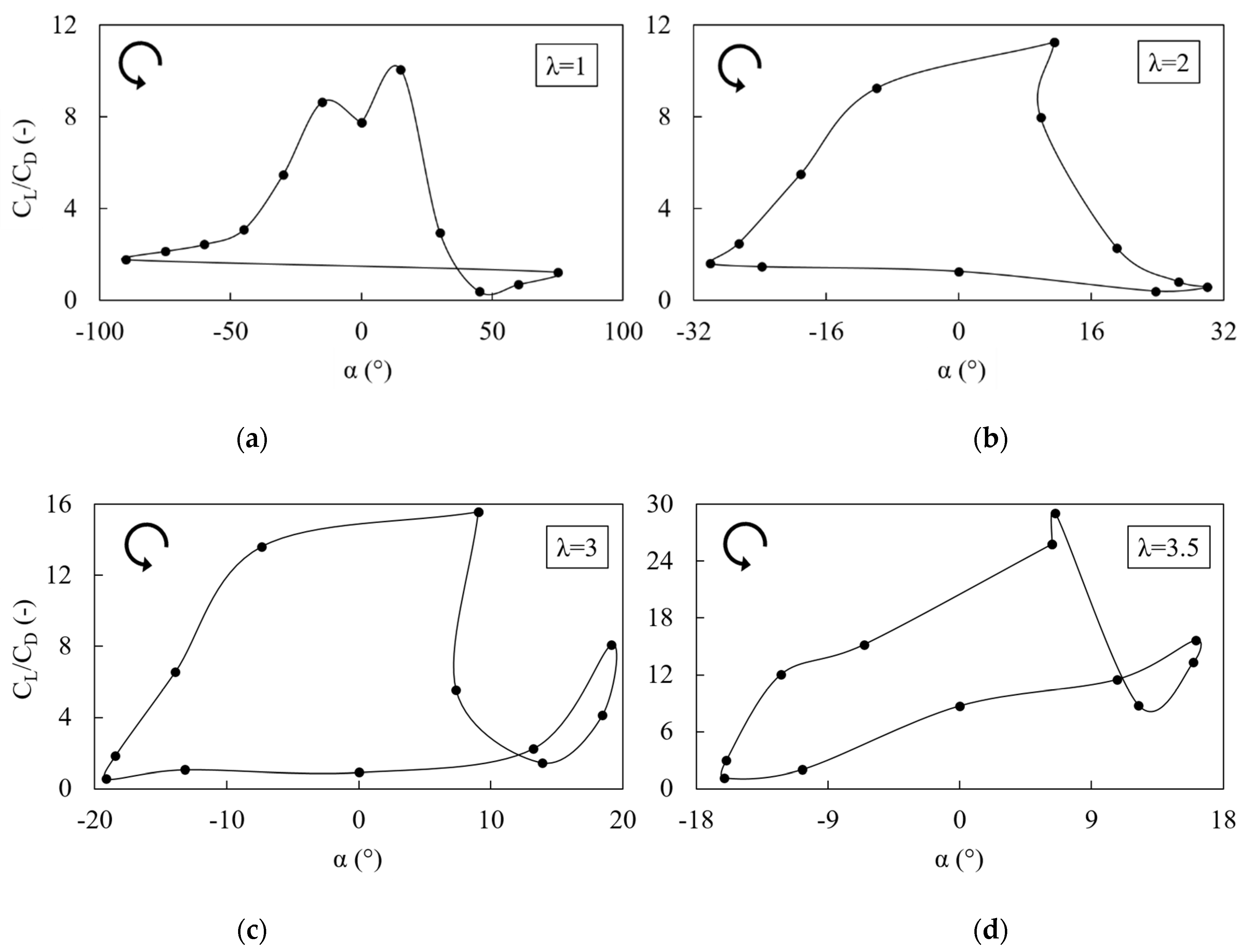
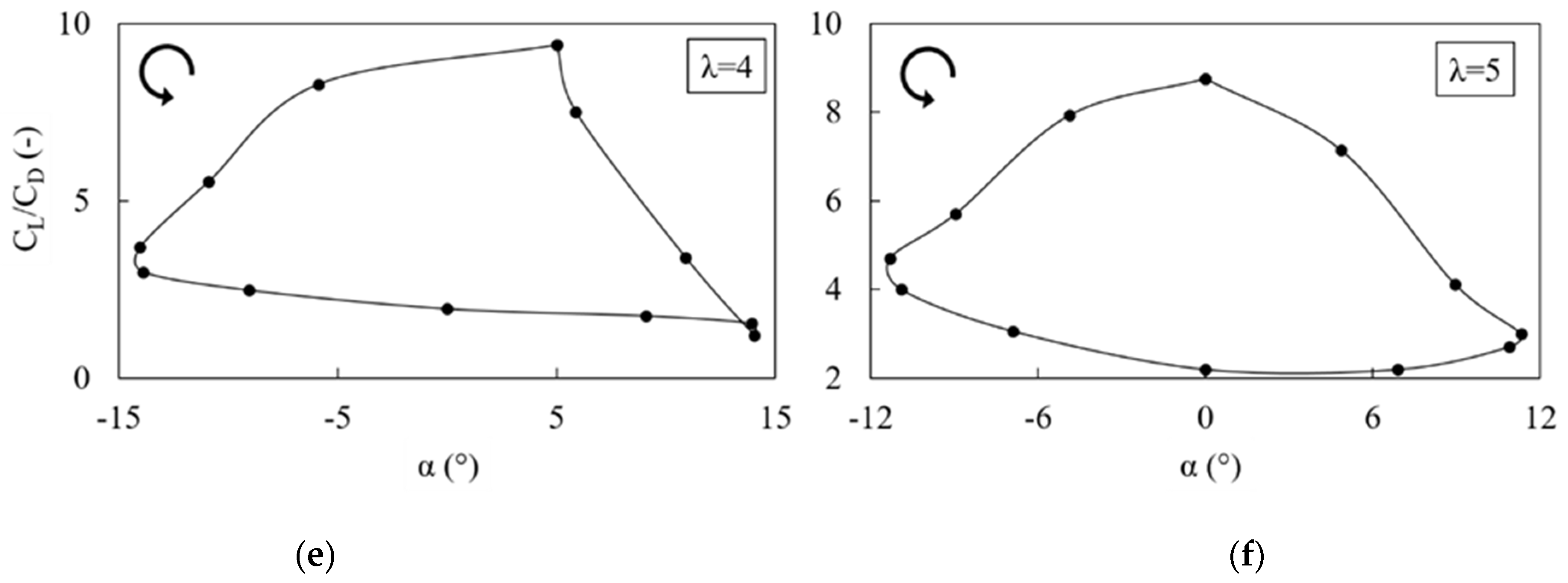
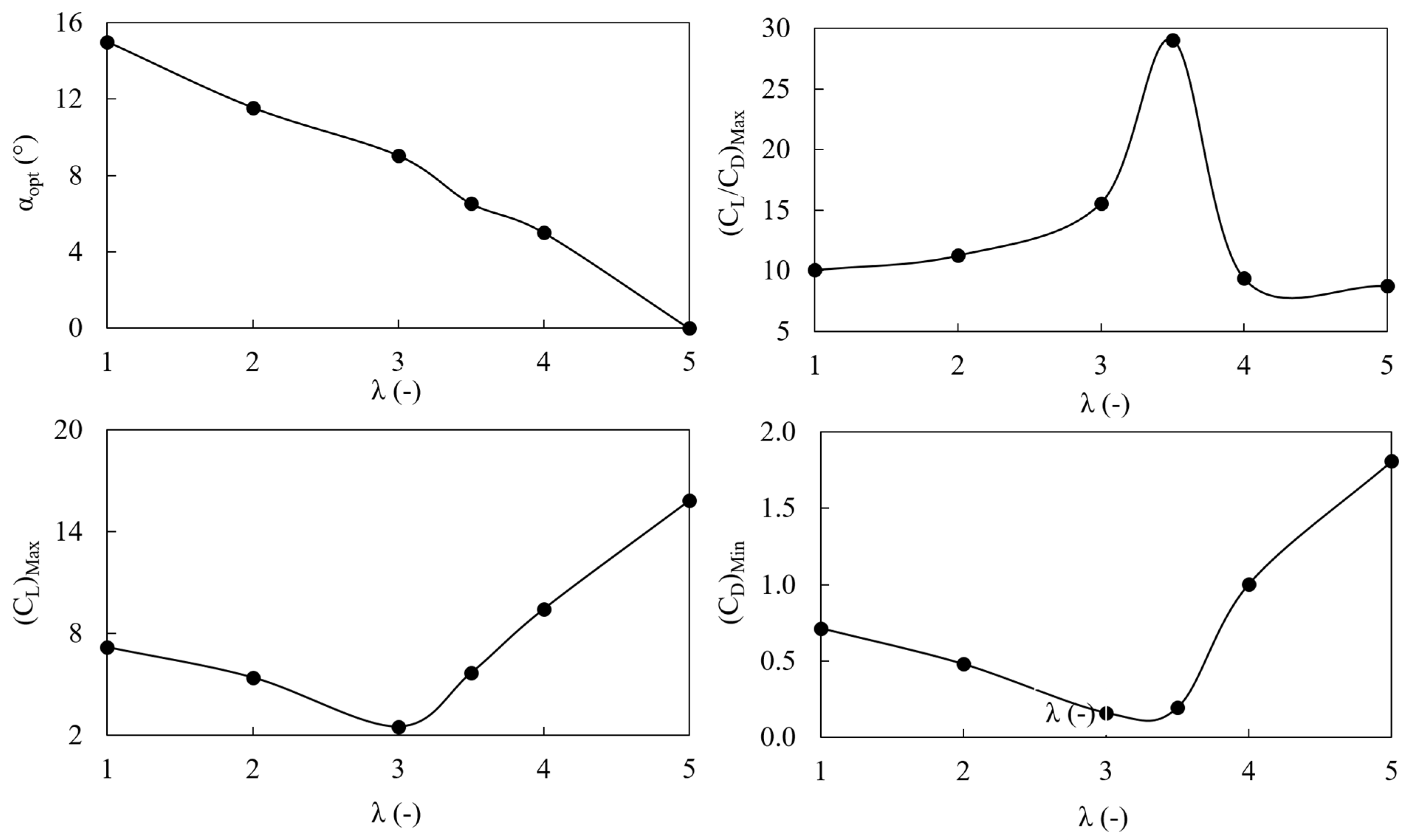
3.2. Effect of TSR on the Distribution of Aerodynamic Forces
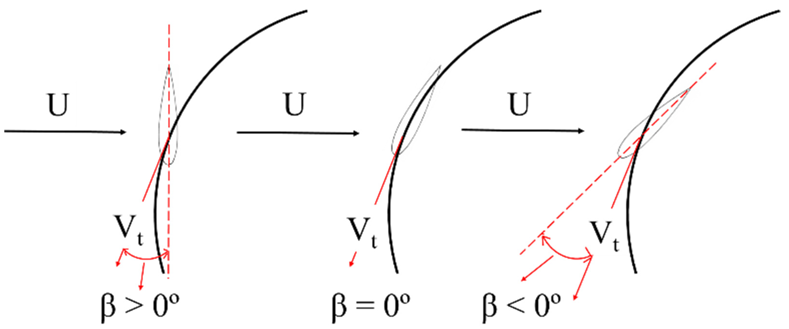
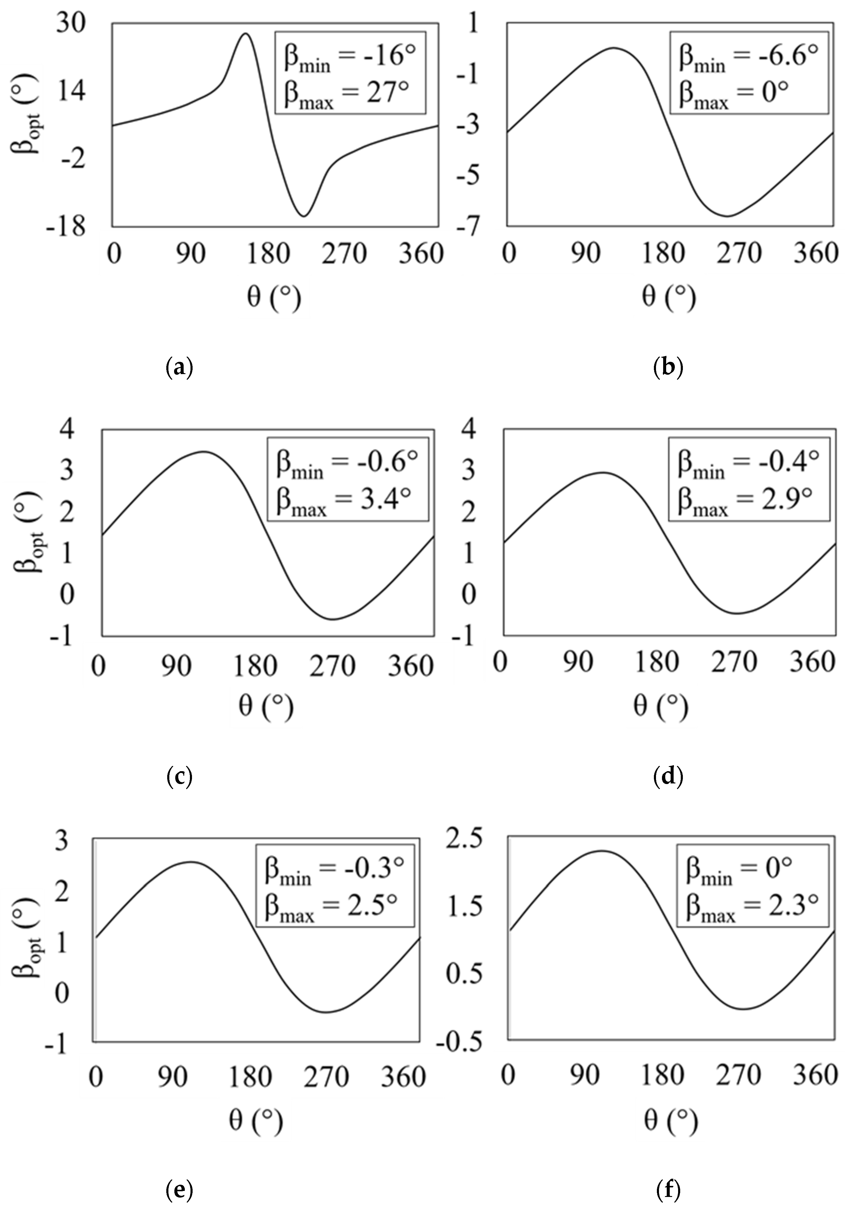
3.3. Pitch Angle Optimization
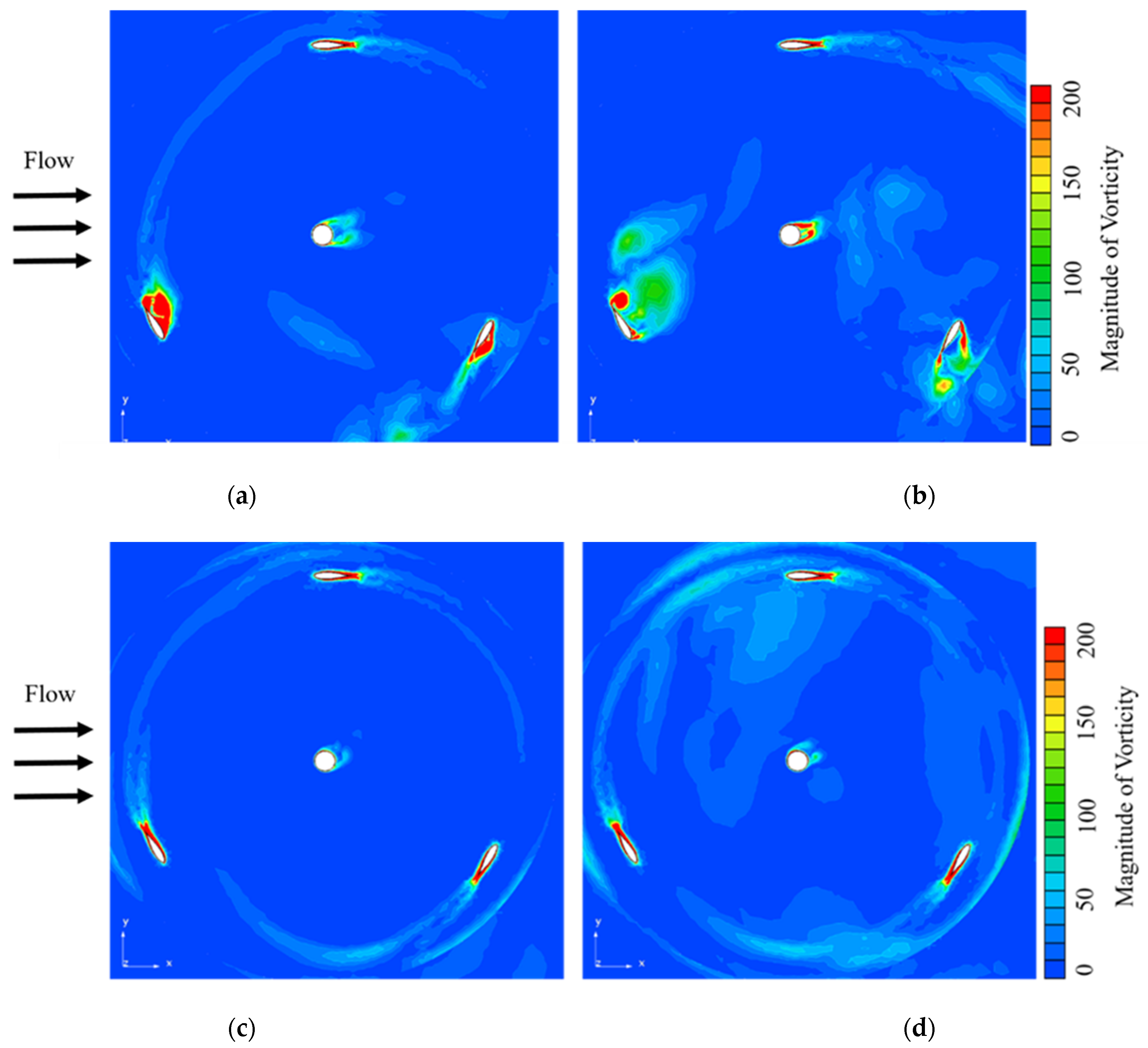
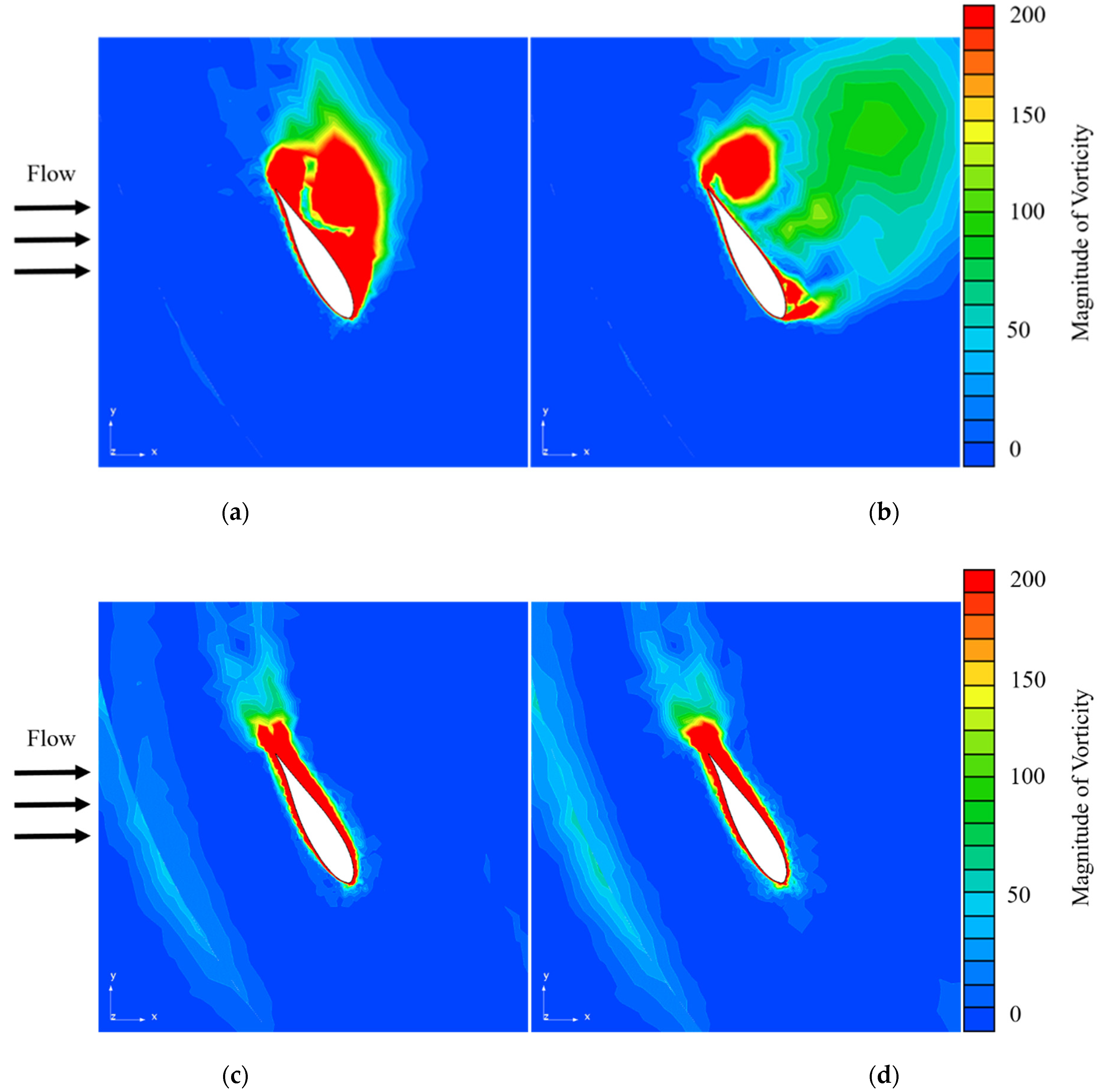
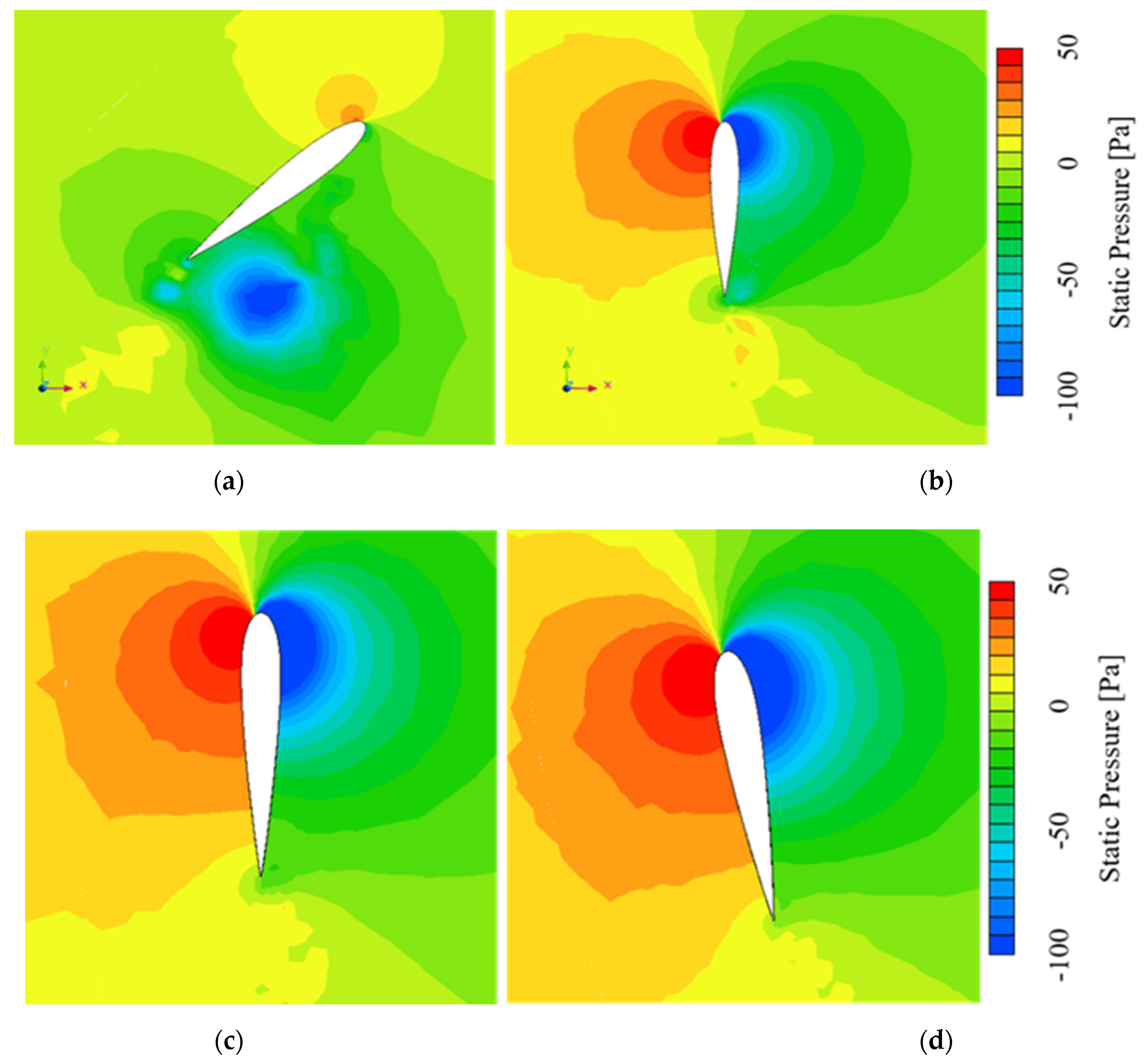
3.4. Internal Flow Analysis
4. Conclusions
Author Contributions
Funding
Institutional Review Board Statement
Informed Consent Statement
Data Availability Statement
Acknowledgments
Conflicts of Interest
List of Abbreviations
| TSR | tip speed ratio |
| HAWT | horizontal axis wind turbine |
| LES | large eddy simulation |
| BC | boundary condition |
| NACA | national advisory committee for aeronautics |
| CI | confidence interval |
| VAWT | vertical axis wind turbine |
| CFD | computational fluid dynamics |
| TI | turbulence intensity |
References
- Howell, R.; Qin, N.; Edwards, J.; Durrani, N. Wind tunnel and numerical study of a small vertical axis wind turbine. Renew. Energy 2010, 35, 412–422. [Google Scholar] [CrossRef] [Green Version]
- Claessens, M. The Design and Testing of Airfoils for Application in Small Vertical Axis Wind Turbines. Master’s Thesis, Faculty of Aerospace Engineering, Delft, The Netherlands, 2006. [Google Scholar]
- Sabaeifard, P.; Razzaghi, H.; Forouzandeh, A. Determination of vertical axis wind turbines optimal configuration through CFD simulations. In Proceedings of the International Conference on Future Environment and Energy, Singapore, 26–28 February 2012; Volume 28. [Google Scholar]
- Ponta, F.; Seminara, J.; Otero, A. On the aerodynamics of variable-geometry oval-trajectory Darrieus wind turbines. Renew. Energy 2007, 32, 35–56. [Google Scholar] [CrossRef]
- Yu, J.; Leu, T.; Miau, J.-J. Investigation of reduced frequency and freestream turbulence effects on dynamic stall of a pitching airfoil. J. Vis. 2017, 20, 31–44. [Google Scholar] [CrossRef]
- Mohamed, M. Performance investigation of H-rotor Darrieus turbine with new airfoil shapes. Energy 2012, 47, 522–530. [Google Scholar] [CrossRef]
- Castelli, M.R.; Benini, E. Effect of blade thickness on Darrieus Vertical-Axis Wind turbine performance. In Proceedings of the ICCMS 2011, 3rd International Conference on Computer Modelling and Simulation, Mumbai, India, 7–9 January 2011. [Google Scholar]
- Joo, S.; Choi, H.; Lee, J. Aerodynamic characteristics of two-bladed H-Darrieus at various solidities and rotating speeds. Energy 2015, 90, 439–451. [Google Scholar] [CrossRef]
- Gupta, R.; Biswas, A. Computational fluid dynamics analysis of a twisted three-bladed H-Darrieus rotor. J. Renew. Sustain. Energy 2010, 2, 043111. [Google Scholar] [CrossRef]
- Patil, R.; Daróczy, L.; Janiga, G.; Thévenin, D. Large eddy simulation of an H-Darrieus rotor. Energy 2018, 160, 388–398. [Google Scholar] [CrossRef]
- Paraschivoiu, I.; Trifu, O.; Saeed, F. H-Darrieus wind turbine with blade pitch control. Int. J. Rotating Mach. 2009, 2009, 505343. [Google Scholar] [CrossRef] [Green Version]
- Gosselin, R.; Dumas, G.; Boudreau, M. Parametric study of H-Darrieus vertical-axis turbines using URANS simulations. In Proceedings of the 21st Annual Conference of the CFD Society of Canada, Sherbrooke, QC, Canada, 6–9 May 2013; p. 16. [Google Scholar]
- Li, Q.A.; Maeda, T.; Kamada, Y.; Murata, J.; Shimizu, K.; Ogasawara, T.; Kasuya, T. Effect of solidity on aerodynamic forces around straight-bladed vertical axis wind turbine by wind tunnel experiments (depending on number of blades). Renew. Energy 2016, 96, 928–939. [Google Scholar] [CrossRef]
- Consul, C.A.; Willden, R.H.J.; Ferrer, E.; McCulloch, M.D. Influence of solidity on the performance of a cross-flow turbine. In Proceedings of the 8th European Wave and Tidal Energy Conference, Uppsala, Sweden, 7–10 September 2009. [Google Scholar]
- Chen, B.; Su, S.; Viola, I.M.; Greated, C.A. Numerical investigation of vertical-axis tidal turbines with sinusoidal pitching blades. Ocean Eng. 2018, 155, 75–87. [Google Scholar] [CrossRef] [Green Version]
- Armstrong, S.; Fiedler, A.; Tullis, S. Flow separation on a high Reynolds number, high solidity vertical axis wind turbine with straight and canted blades and canted blades with fences. Renew. Energy 2012, 41, 13–22. [Google Scholar] [CrossRef]
- Ali, S.; Lee, S.M.; Jang, C.M. Effects of instantaneous tangential velocity on the aerodynamic performance of an H-Darrieus wind turbine. Energy Convers. Manag. 2018, 171, 1322–1338. [Google Scholar] [CrossRef]
- Jang, C.M.; Furukawa, M.; Inoue, M. Analysis of Vortical Flow Field in a Propeller Fan by LDV Measurements and LES—Part I: Three-Dimensional Vortical Flow Structures. Trans. ASME J. Fluids Eng. 2001, 123, 748–754. [Google Scholar] [CrossRef]


| Parameter | Value |
|---|---|
| Blade profile | NACA 0015 |
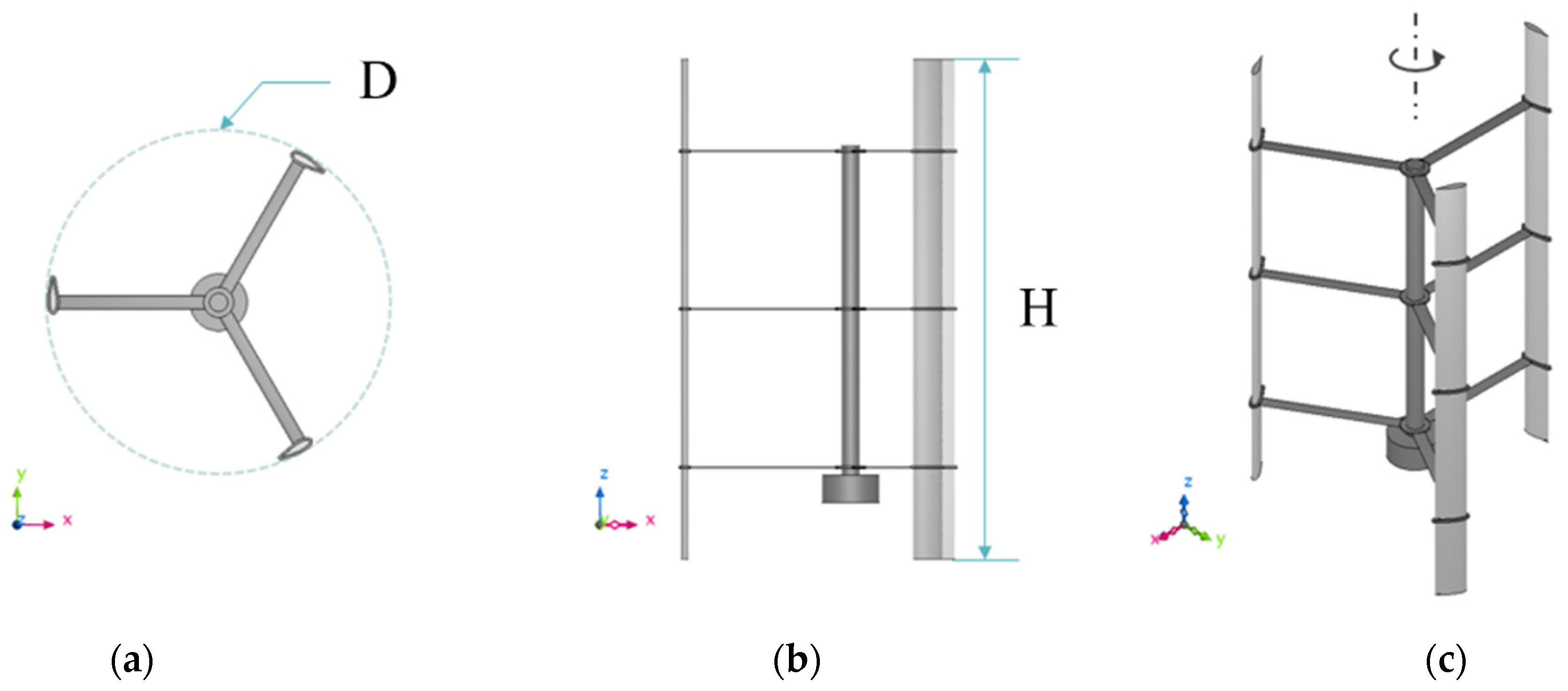
| Rotational diameter (D) | 2 m |
| Blade height (H) | 3 m |
| Chord length (c) | 0.2 m |
| Turbine solidity (S) | 0.1 |
| Parameter | Value |
|---|---|
| Mesh type | tetrahedral and prism |
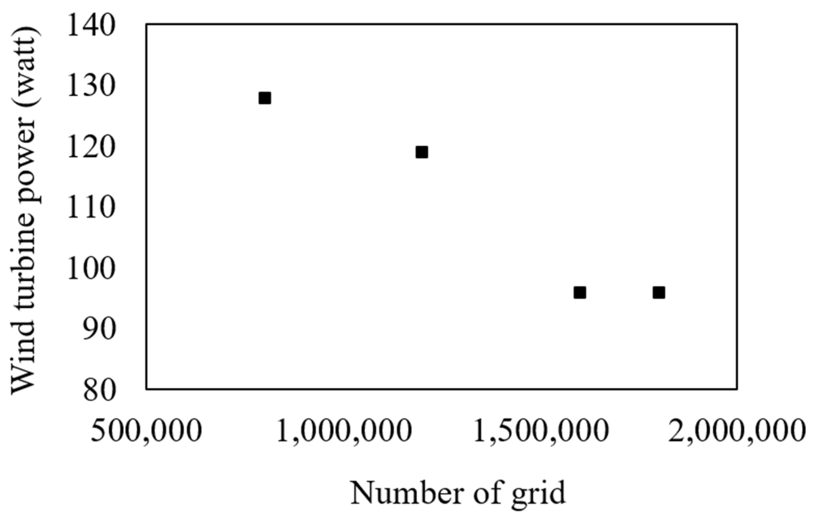
| Number of total elements | 1,600,000 |
| Number of prism layers (Turbine) | 5 |
| Number of prism layers (Wall) | 3 |
| TSR (-) | CN (-) | dθ/dt (°/s) | dt (s) |
|---|---|---|---|
| 1 | 2.68 | 0.1 | 0.00035 |
| 2 | 1.88 | 0.1 | 0.000176 |
| 3 | 1.43 | 0.1 | 0.000115 |
| 4 | 1.37 | 0.1 | 0.000088 |
| 5 | 1.37 | 0.1 | 0.00008 |
Publisher’s Note: MDPI stays neutral with regard to jurisdictional claims in published maps and institutional affiliations. |
© 2021 by the authors. Licensee MDPI, Basel, Switzerland. This article is an open access article distributed under the terms and conditions of the Creative Commons Attribution (CC BY) license (https://creativecommons.org/licenses/by/4.0/).
Share and Cite
Ali, S.; Jang, C.-M. Effects of Tip Speed Ratios on the Blade Forces of a Small H-Darrieus Wind Turbine. Energies 2021, 14, 4025. https://doi.org/10.3390/en14134025
Ali S, Jang C-M. Effects of Tip Speed Ratios on the Blade Forces of a Small H-Darrieus Wind Turbine. Energies. 2021; 14(13):4025. https://doi.org/10.3390/en14134025
Chicago/Turabian StyleAli, Sajid, and Choon-Man Jang. 2021. "Effects of Tip Speed Ratios on the Blade Forces of a Small H-Darrieus Wind Turbine" Energies 14, no. 13: 4025. https://doi.org/10.3390/en14134025
APA StyleAli, S., & Jang, C.-M. (2021). Effects of Tip Speed Ratios on the Blade Forces of a Small H-Darrieus Wind Turbine. Energies, 14(13), 4025. https://doi.org/10.3390/en14134025