Article

Comparison and Validation of Hydrodynamic Theories for Wave Energy Converter Modelling

1
College of Engineering, Oregon State University, Corvallis, OR 97331, USA
2
Department of Mechanical Engineering, University of Washington, Seattle, WA 98195, USA
3
C-Power, Corvallis, OR 97333, USA
4
Pacific Northwest National Laboratory, Richland, WA 99354, USA
*
Author to whom correspondence should be addressed.
Energies 2021, 14(13), 3959; https://doi.org/10.3390/en14133959
Submission received: 4 June 2021 / Revised: 26 June 2021 / Accepted: 29 June 2021 / Published: 1 July 2021

Abstract

:
Dynamic Wave Energy Converter (WEC) models utilize a wide variety of fundamental hydrodynamic theories. When incorporating novel hydrodynamic theories into numerical models, there are distinct impacts on WEC rigid body motions, cable dynamics, and final power production. This paper focuses on developing an understanding of the influence several refined hydrodynamic theories have on WEC dynamics, including weakly nonlinear Froude-Krylov and hydrostatic forces, body-to-body interactions, and dynamic cable modelling. All theories have evolved from simpler approaches and are of importance to a wide array of WEC archetypes. This study quantifies the impact these theories have on modelling accuracy through a WEC case study. Theoretical differences are first explored in a regular sea state. Subsequently, numerical validation efforts are performed against field data following wave reconstruction techniques. Comparisons of significance are WEC motion and cable tension. It is shown that weakly nonlinear Froude-Krylov and hydrostatic force calculations and dynamic cable modelling both significantly improve simulated WEC dynamics. However, body-to-body interactions are not found to impact simulated WEC dynamics.

1. Introduction

Numerical modelling tools expedite the development of the wave energy sector by aiding in the design, analysis, and optimization of wave energy converter (WEC) devices. These tools aid in capturing the complex interactions between rigid bodies dynamics, hydrodynamics, hydrostatics, power take-off (PTO) units, and control systems present in WECs. With design decisions based heavily on predictions from simulation tools, it is of vital importance to verify and validate WEC numerical software [1]. Users have the choice to include numerous refined numerical theories within WEC software that may increase the accuracy of simulated dynamics.
Numerical theories have evolved with the intention of improving the numerical representation of the inherently complex dynamics of floating offshore systems. For instance, floating body hydrostatic and Froude-Krylov force calculations traditionally concern a static submerged portion of the body [2]. However, many floating bodies have dynamic wetted surface areas. Weakly nonlinear Froude-Krylov and hydrostatic force calculations pertain to incorporating this changing wetted surface area into WEC dynamics [3]. Additionally, a rigid body usually has 6 degrees of freedom corresponding to the particular body’s translational and rotational motion [2]. However, rigid bodies in close proximity to one another impact forces on each other, and body-to-body interactions concern integrating these cross-body forces into a numerical model [4]. Additionally, when marine cables attach to a rigid body, forces cause structural deformation of the cable, and marine cable models, which have evolved from simple mass-spring-dampers to dynamic cable models, simulate such structural responses [5]. The three aforementioned modelling techniques are all theoretical refinements that may pertain to modelling a particular WEC’s dynamics more accurately.
Several studies have focused on the implementation of an refined hydrodynamic theories. Combourieu et al. determined that including body-to-body interactions is significant for a floating oscillating flap device [1]. Wendt et al. focused on the importance of nonlinear Froude-Krylov and hydrostatic force calculations for a semi-submerged sphere and a heaving float, and determined that nonlinear effects are most significant for large motions in large waves [3]. Paduano et al. compared and validated different cable models for moored floating WECs, and found close agreement between a quasi-static and dynamic cable models [6]. All of these comparisons aid a particular aspect of the WEC design process. However, numerous theories are often pertinent for a singular WEC, and the present lack of a comprehensive review of the associated theoretical impacts creates uncertainty and an inability to cross validate prior research efforts.
The objectives of this study are two-fold: (1) determine how weakly nonlinear Froude-Krylov and hydrostatic force calculations, body-to-body interactions, and/or dynamic cable models impact a WEC’s simulated dynamics, and (2) to validate numerical models against field measurement data. Section 2 lays out various WEC numerical modelling theories. Section 3 discusses the software and numerical model implementation of this study. Section 4 presents the particular WEC this study focuses upon. Section 5 shows the results and discussion for the code-to-code and code-to-field comparisons. Section 6 discusses this study’s conclusions and the opportunities for future work.

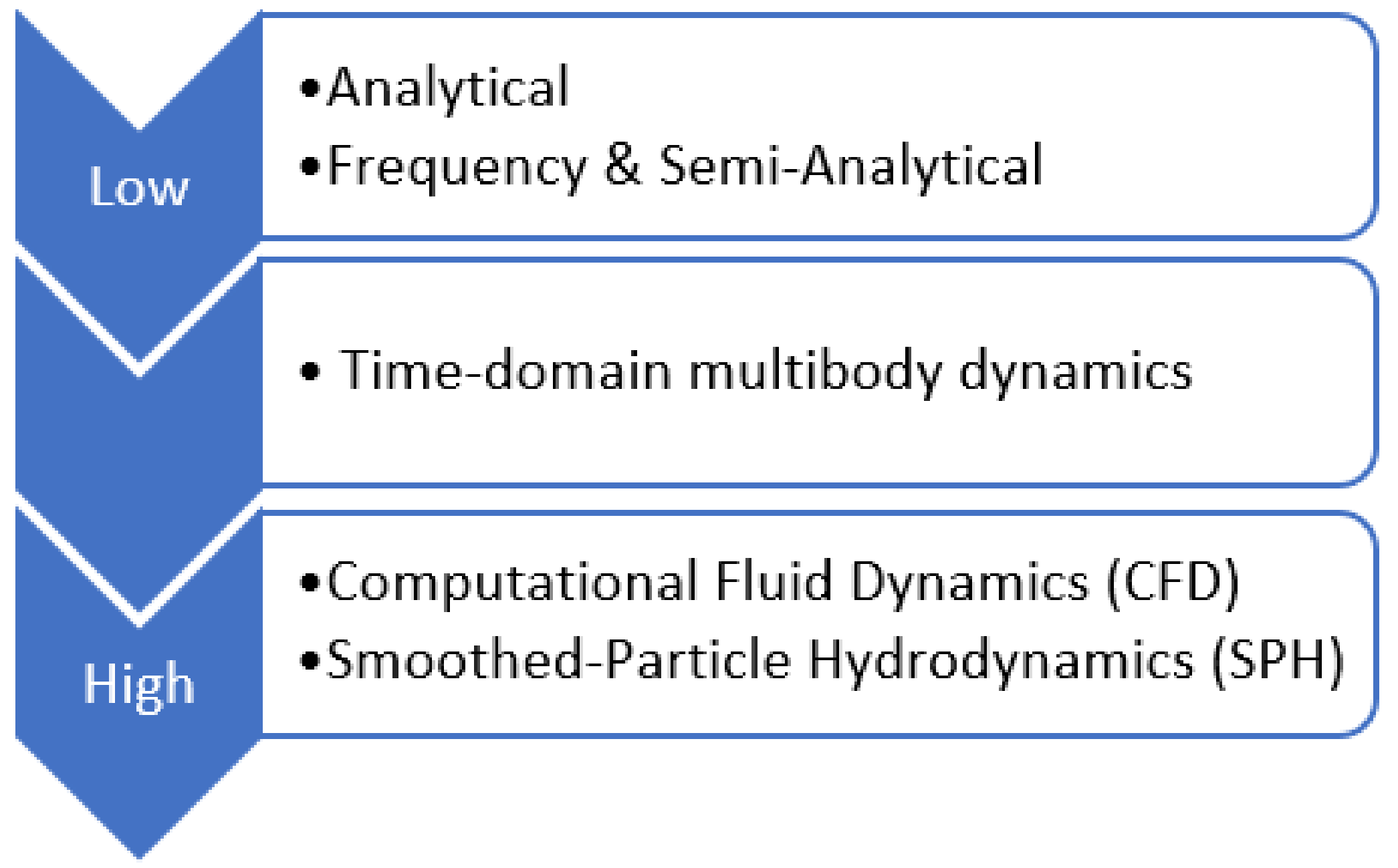
2. Wave Energy Converter Numerical Modelling Theory

WEC modelling varies in terms of fidelity of the simulation environment and the WEC model’s inherent assumptions. Many WEC models aim to approximate Newton’s 2nd law of motion. Figure 1 provides A broad layout of different WEC modelling approaches.
The lowest fidelity WEC models employ analytical approximations of these forces, as in Zhao et al., whom investigate the hydrodynamics of multi-pontoon floating platforms that work as an oscillating water column WECs [7]. However, these low-fidelity approaches rely on many assumptions that simplify WEC dynamics greatly. A slightly more robust approach performs calculations solely in the frequency domain to predict WEC behavior, as in Pastor and Liu, whom model a heaving point absorber WEC in the frequency domain [8]. Time-domain multibody dynamic modelling is a more robust approach, which this study incorporates. This approach employs coefficients found in the frequency domain following linear potential flow theory, and specifies additional forces in the time-domain through a multibody dynamic solver [1,9,10]. The highest fidelity numerical models provide the most robust and computationally expensive approach to approximating Newton’s 2nd law of motion numerically, and concern computational fluid dynamics (CFD) and smoothed particle hydrodynamics (SPH). CFD and SPH differ in that CFD treats a fluid in an Eulerian reference frame, whereas SPH is inherently Lagrangian [11,12]. CFD and SPH are the most capable of approximating the Navier–Stokes equations for WEC dynamics. Active practice in the wave energy sector employs numerical modelling with varying levels of fidelity. However, the wave energy sector is highly reliant on time-domain multibody dynamic models, and so this study restricts itself to that approach.

2.1. Baseline WEC Modelling Theory

Time-domain representations of WEC dynamics enable the inclusion of nonlinear and higher order numerical schemes. The baseline time-domain representation of the WEC and its associated forces are shown in Equation (1):
m + m a x ¨ = F exc + F HP + F Rad + F pto + F D + F c ,
In Equation (1) the left-hand side concerns the inertial force, which includes the dry mass of the body, m , the added mass at the infinite frequency, m a , and the rigid body acceleration, x ¨ . The right-hand side of Equation (1) includes all remaining pertinent forces present in the WEC system: F exc is the excitation wave force, F HP is the hydrostatic restoring force, F Rad is the radiation force (composed of radiation damping and frequency-dependent added mass), F pto is the PTO force, F D is the drag force, and F c is the overall cable force [1].

2.1.1. Excitation Force

The excitation force, F exc , is composed of the Froude-Krylov force, F FK , and diffraction force, F diff , and results from the unsteady pressure field due to waves. Particularly, F FK concerns the incident wave force, and is represented by:
F FK = S w ρ ge kz η ds ,
where S w is the wetted surface area, ρ is the fluid density, g is gravitational acceleration, k is the wave number, z is the vertical position, and η is the free surface elevation [2]. The diffraction force, F diff , results from the alteration of a wave field due to the presence of a rigid body, as shown in Equation (4):
F diff = ρ S w ϕ diff t nds ,
where ϕ diff is the diffraction wave potential, and n is the body’s normal vector. The upper boundary for S w in Equations (2)–(4) is the free-surface [2].

2.1.2. Hydrostatic Force

The hydrostatic force, F HP , concerns the pressure loading of a liquid on a submerged rigid body. F HP , is represented by:
F HP = ρ g S w zds .
The upper boundary for S w in Equations (2)–(4) is the free-surface [2].

2.1.3. Radiation Force

The radiation force, F Rad , represents the rigid body’s response to a wave impulse. F Rad , is represented by:
F Rad = 0 K r t τ   x ˙ d τ .
In Equation (5) K r is the radiation impulse response function determined from frequency-dependent added mass, m a , and damping coefficients, C rad . Rigid body velocities are specified by x ˙ [2,13].

2.1.4. Power Take-Off (PTO) Force

The PTO influences a WEC’s motions and the resulting power output, thereby impacting WEC performance [9]. PTO systems are designed in the time-domain, and are inherently unique for a particular WEC. The WEC’s power take-off force, F pto , generally concerns a hydraulic PTO system [14], a pneumatic air turbine transfer PTO system [10,14], or a mechanical PTO system [15]. F pto calculations are dependent on the type of PTO system and the particular WEC characteristics; therefore, there is no uniform F pto equation [15].

2.1.5. Viscous Drag Force

Viscous drag is the resistive force acting from the fluid on a rigid body, and the drag force, F D , formulates from the fluid’s tendency to withstand deformation. Equation (6) characterizes F D :
F D = C D ρ A D 2 x ˙ x ˙ .
In Equation (6) C D is the structure’s specific quadratic drag coefficient, ρ is the fluid density, A D is the characteristic area, and x ˙ is the rigid body’s velocity [16].

2.1.6. Cable Force

The cable force, F c , pertains to the force marine cables induce to secure floating systems to a fixed location or to connect rigid bodies. Cable forces in their most simplistic form may be calculated as mass-spring-dampers:
F c = K c x C c x ˙ .
In Equation (7), K c and C c are cable stiffness and damping coefficient matrices, and x and x ˙ are the relative displacement and velocity of the body, respectively [17].

2.2. Refined Numerical Theories

WEC modelling approaches are constantly evolving, and novel hydrodynamic theories reflect advances in understanding of WEC dynamic behavior. Each novel numerical theory must be continuously verified and validated. In this work, the theories of focus are weakly nonlinear Froude-Krylov and hydrostatic calculations, body-to-body (B2B) interactions, and dynamic cable models. These theories are chosen because they are pertinent to many WEC archetypes, and there is a present lack in literature on the verification and validation for systems that concern multiple of the aforementioned theories.

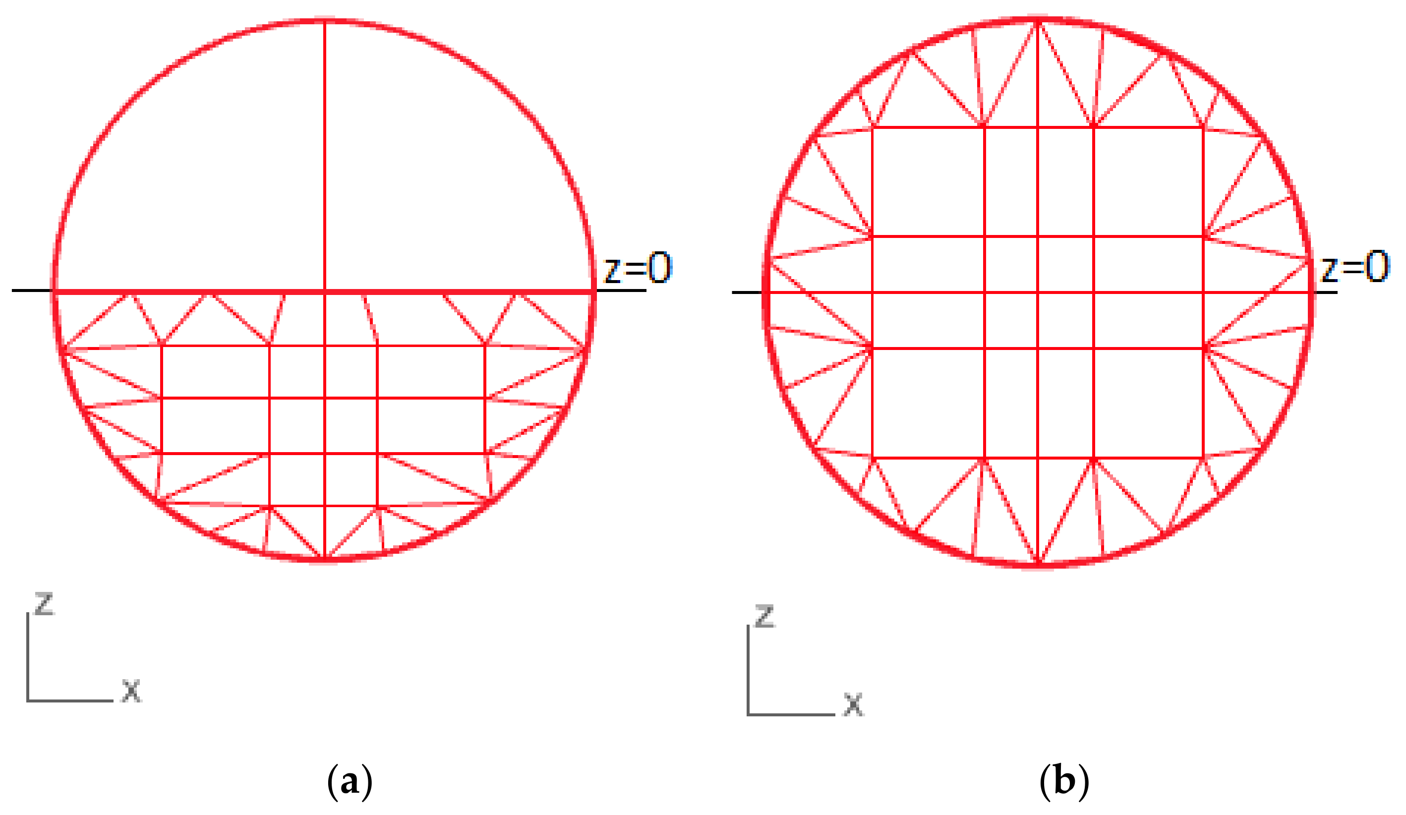
2.2.1. Weakly Nonlinear Froude-Krylov and Hydrostatic Forces

The standard practice for time-domain multibody dynamic modelling Froude-Krylov and hydrostatic forces are approximated from linear potential flow theory. These forces are calculated from the equilibrium position of the body using frequency-domain terms, which are found through a boundary element method BEM solver such as WAMIT [18] or NEMOH [19]. For time-domain implementation, F FK coefficients are only dependent on wave frequency, and F HP coefficients are constant.
Weakly nonlinear models extend linear potential flow theory by incorporating weakly nonlinear terms, which are induced by instantaneous water surface elevation and the exact position of the rigid body’s geometry rather than mean surface elevation as in linear models [3,20,21]. Weakly nonlinear terms are only of importance for rigid bodies with a dynamic wetted surface area, and are dependent upon the portion of a geometric mesh above the still water line, as shown in Figure 2b [16,17]. This differs from linear models, where the submerged mesh is static, as displayed in Figure 2a.
For WEC cases concerning rigid body(s) with significant dynamic wetted surface areas, the inclusion of weakly nonlinear calculations may considerably improve a WEC’s simulated power capture assessment [3,22,23]. For calculation of instantaneous water surface elevation and associated pressure fields, linear wave theory is extended for a given computational mesh at the surface. Initial calculations of flow velocity and pressure show unrealistically large values for submerged mesh panels above still water level. Time-varying instantaneous surface elevation may be found by employing Wheeler wave stretching, where the instantaneous vertical position, z * , is represented by [24]:
z * = h h + z h + η h .
In Equation (8) h is the mean water depth, and η is the instantaneous water surface elevation [20,21,24,25].

2.2.2. Body-to-Body Interactions

When oscillating rigid bodies are in close proximity, hydrodynamic interactions can be modelled with additional components. In multibody systems, body-to-body interactions allow for the motion of one body to impart a force on nearby rigid bodies [18].
B2B interactions may be influential in the correct characterization of WEC performance. B2B hydrodynamics may reduce WEC float’s motion, thereby, decreasing energy production [26]. If cross-coupled coefficients are important, then a rigid body’s radiation force, F Rad , is extended. For example, in a two-body heaving system where cross-coupled terms are important, the total radiation force of rigid body 1,   F Rad   1 , is [4]:
F Rad   1 = F Rad   11 z ¨ 1 , z ˙ 1 + F Rad   12 z ¨ 2 , z ˙ 2 .  
In Equation (9) F Rad   11 is the radiation force on rigid body 1 due to the motion of rigid body 1, and F Rad   12 is the radiation force on rigid body 1 due to the motion of rigid body 2.
B2B interactions are inevitable in multibody systems; however, the importance of the inclusion of B2B interactions is not well-established. Depending upon the relative magnitude of a rigid body’s self- vs. cross-coupled frequency coefficients, it may be acceptable to neglect B2B interactions for a multibody WEC model, for in such cases the added computational expense has an insignificant impact on WEC dynamics [4,27]. For example, following Starrett et al., B2B interactions for an array of 5 single-body WECs situated approximately 50 m apart were found insignificant [4]. The importance of B2B interactions corresponds to the distance between rigid bodies [27]. In order to show how B2B interactions impact the system’s dynamics more clearly, it is important to verify and validate this extension to the calculated hydrodynamics of the system.

2.2.3. Dynamic Cables

When a cable attaches to a rigid body, reaction loads corresponding to the cable’s elastic deformation apply as external forces on the rigid body [28]. Marine cable dynamic modelling is governed by nonlinear partial differential equations in terms of a space and time [5]. A solution to these equations may be obtained by linearizing the equations’ dynamics about an equilibrium condition or employing numerical models in order to gain an approximation of the equations [29]. Lumped mass cable models define a cable by forces due to the weight, buoyancy, drag, and added mass at specified node positions [30,31,32,33,34]. These models account for cable elasticity through a series of point masses in a series of linear visco-elastic elements [34]. Cable loads may be expressed by [29]:
F c =   m c R ¨ = ( K ε + K κ + K τ ) r 0 T   r 0 T   r n T   r n T + W + H .
In Equation (10), F c is the force vector of the specified cable, m c is the mass of the cable element, K ε is the axial stiffness of the cable, K κ is the cable bending stiffness, K τ is the torsional stiffness, W is the combined cable element weight and buoyancy, and H is the hydrodynamic load in terms of the global reference frame. The cable has n nodes, and a cable element is connected by two nodes. The term r i T refers to the position of the i th node, and r i T refers to that same node’s curvature, where i = 0 , , n . Dynamic cable models presently vary as to the degree to which nonlinearity or high-order polynomials are included in the cable discretization scheme [35]. Linear lumped mass models neglect curvature and corresponding nonlinearities such as bending stiffness and torsion [29]. The MooDy model applies high-order polynomials for a cable’s spatial discretization, which makes the numerical model well-suited for snap-loaded design [36]. Furthermore, it has been shown that including nonlinear terms such as bending stiffness when modelling cable dynamics helps prevent model instability [35,37]. To facilitate this, Buckham et al. present a method to incorporate curvature variables present in the dynamics of a continuous cable with cubic cable elements using finite element methods [38]. With some WEC designs, such as a PTO tethered system, the necessity of dynamic and robust finite element cable models for acceptable representation of the system’s dynamics is unclear and, hence, an objective of this study.

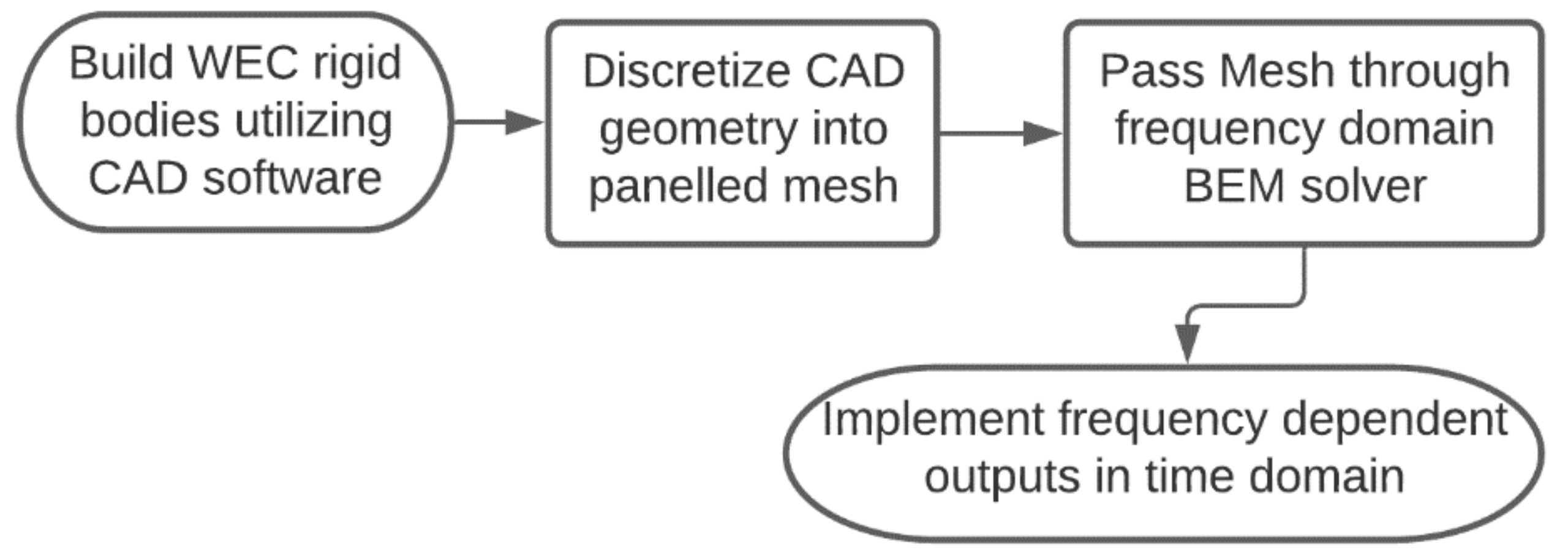
3. Numerical Theory Implementations

Numerical models of WECs are an integral part of designing these floating energy absorption systems. The computational tools investigated involve the geometric build of a WEC to time-domain representation of the WEC’s equation of motion. Two common WEC simulation tools are ProteusDS [39] and WEC-Sim [40]. With these codes, this study compares the implementation of the fundamental hydrodynamic theories, and validates simulation accuracy against experimental testing data.
The numerical modelling process follows that presented by Bailey et al. [9], which implements a wave-to-wire methodology and shows the necessary pre-processing to model a WEC in the time-domain. As shown in Figure 3, the numerical process begins with a geometric build formed with a CAD model in SOLIDWORKS [41] or similar packages. Then, the WEC geometry is discretized in Rhinoceros3D [42] or similar meshing software. The mesh is then passed through a frequency-domain Boundary Element Method (BEM) software, such as WAMIT [18], ShipMo3D [43], or NEMOH [44]. The BEM software resolves the velocity potential and fluid pressure for the entire submerged mesh, and outputs frequency dependent F exc , F HP and F Rad coefficients. Time-domain multibody dynamic software such as ProteusDS or WEC-Sim implements these frequency-dependent force coefficients as all other forces listed in Equation (1) into the time-domain.

3.1. ProteusDS

ProteusDS is a commercial time-domain analysis software package that tests virtual prototypes of many marine applications. The software focuses on determining the dynamic response of structures subject to currents, waves, and/or wind. Rigid body connections in ProteusDS are represented through the development of an articulated body algorithm (ABA) connection tool, which decreases the complexity of connections by reducing the degrees of freedom of the downstream rigid body to the number of degrees of freedom of an upstream joint [1,39]. Furthermore, ProteusDS has the capability to link with MATLAB/Simulink through an Application Programming Interface, allowing for control system customization [45]. In the time-domain, F exc , F HP and F Rad are calculated from BEM software. With weakly nonlinear terms, F exc and F HP coefficients depend on the instantaneous surface elevation, and utilize the Wheeler wave stretching method [24]. F Rad is only computed for a rigid body’s 6 degrees of freedom in ProteusDS, for ProteusDS does not account for B2B interactions. F pto is calculated with specified joint damping and stiffness coefficients with the ABA connection. F D is calculated with Equation (6) about the center of pressure acting on the submerged mesh. F c is calculated in ProteusDS utilizing approach of Buckham et al., with material properties specified for the cable following Equation (10) [38,39].

3.2. WEC-Sim

The Wave Energy Converter SIMulator (WEC-Sim) numerical tool is an open-source software developed by Sandia National Laboratory and the National Renewable Energy Laboratory with the U.S. Department of Energy. WEC-Sim is developed in the MATLAB/SIMULINK environment using the multibody dynamics solver SimMechanics, allowing for control system and model customization. WEC-Sim models are comprised of rigid bodies, motion constraints, PTO units, and marine cable systems. Simulations are time-domain approximations to the WEC’s governing equations of motion [1].
As in ProteusDS, F exc , F HP , and F Rad are computed in BEM software unless simulations include weakly nonlinear forces, for which scenarios F exc and F HP rely upon the instantaneous surface elevation, and employ the Wheeler wave stretching method [24]. F Rad calculation in WEC-Sim are dependent upon whether or not simulations enable B2B interactions [40]. F pto is calculated with specified joint damping and stiffness coefficients with a WEC-Sim SIMULINK joint [40]. F D is calculated with Equation (6) about each rigid body’s specified reference areas [40]. This study performed simulations with WEC-Sim v4.2, which is coupled with MoorDyn C, a dynamic cable model [46]. However, MoorDyn C only permits a cable to connect to a rigid body to the seafloor, and so multibody cable connections are prohibited [40,46]. To circumnavigate this matter, a pseudo-cable representation as a massless rod is implemented, where F c is modelled as a simple spring for, as in Equation (7) [40].

4. Case Study WEC and Field Campaign

This study aims to validate the refined numerical theories against field deployment data (in addition to measuring the relative impact these theories have on the WEC’s simulated environment). This study takes measurements from the Wave Energy Buoy that Self-deploys (WEBS) device for model validation.

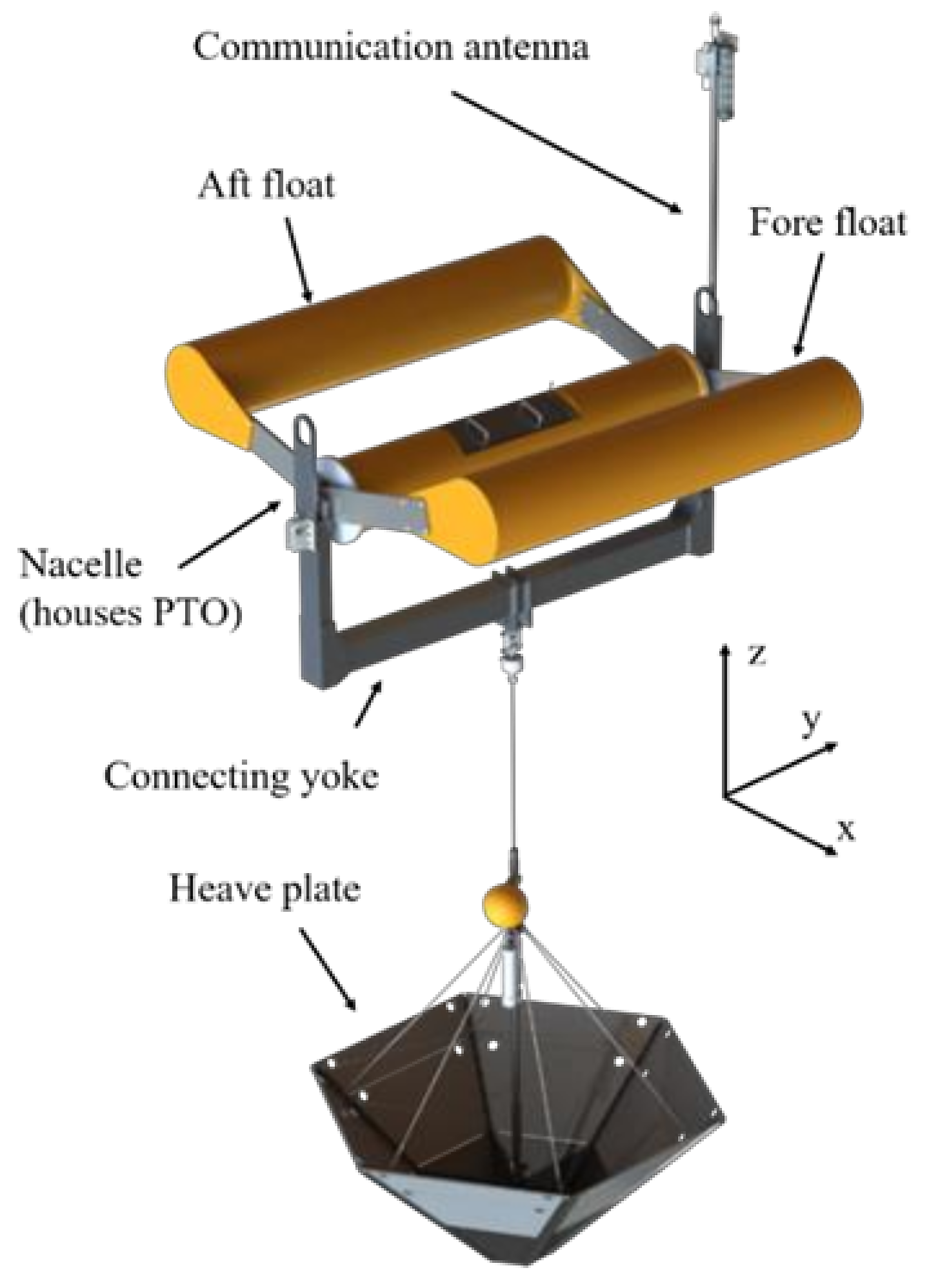
4.1. Wave Energy Buoy That Self-Deploys (WEBS)

WEBS is a multibody point absorber developed by researchers from the University of Washington’s Applied Physics Laboratory and C-Power Technologies. WEBS consists of a three-body surface float connected by a tether to a submerged heave plate as shown in Figure 4. The aft float is rigidly connected to the nacelle, which houses a gear box and rotary generator. The fore float rotates about the nacelle by means of a thru-axle on the nacelle to drive the generator. The tether is ¾” Samson Tenex, which has a breaking strength of 90 kN. The heave plate is a hexagonal cone located 60 m below the surface. This multibody device is designed for a sea state concerning a significant wave height of 1.8 m and an energy period of 7.9 s [47].
The relevant performance metrics of WEBS are the relative float angular velocity, tether tension, and heave plate position. The float angular velocity (with respect to the nacelle) is derived from an encoder’s position, and, when paired with knowledge of the PTO, this metric allows for the calculation of power generation. Tether tension is a key indicator of loads that the WEC experiences, and was directly measured by load cells located along the tether. The heave plate position is derived from pressure sensors on the WEC heave plate, and the heave plate’s operational mobility is a critical measure of design performance.
Heave plate heave displacement measurements include surface elevation changes, however, numerical values for heave plate depth are measured from the mean sea level and do not take instantaneous surface elevation into account. This is corrected by superimposing the surface elevation time-series on the numerical heave plate depth values. Drag coefficients are specified from experimental data found in Rusch et al. and listed in Table 1 [47].
The PTO system for this study is a mechanical PTO, where energy is generated as a torque through a rotary generator between oscillating bodies:
F p t o = K m e c h θ 2 θ 1 C g e n θ ˙ 2 θ ˙ 1 .
In Equation (11), K m e c h is the mechanical spring stiffness, relative pitch orientation is denoted θ 2 θ 1 , the PTO damping coefficient is given by C g e n , and relative pitch angular velocity is denoted by θ ˙ 2 θ ˙ 1 . The PTO system concerns a rotational joint with a stiffness coefficient value of 668 N/m and damping coefficient of 2400 Nms/rad [47].

4.2. Field Campaign Details

WEBS was deployed 9 nautical miles west of Moss Landing in Monterey Bay, CA, USA on 17 and 18 August 2016. Surface Wave Instrument Float with Tracking (SWIFT) buoys deployed alongside WEBS provide wind and wave measurements throughout deployment [48]. Data was collected over an 8-h period. During deployment, SWIFT buoy measurements found an average wave height of 1.33 m and period of 9.66 s [47].

Wave Reconstruction Methods

Wave spectra models and statistical techniques have been the norm for representing environmental conditions in numerical WEC models and provide statistical complementarity. Wave reconstruction is a novel concept determined to find predictions of instantaneous wave energy, and allows for direct time-domain comparison. There are two standard approaches to wave reconstruction: (1) the fixed-time approach, and (2) the fixed-point approach. The fixed-time approach takes wave elevation measurements via snapshots over a fixed area at a single instant, viewing the wavefield with a Eulerian reference frame [49]. The fixed-point approach creates a time series of fixed points to find wave elevation measurements, which is an inherently Lagrangian approach [49]. This study follows the fixed-point approach, where heave data is collected at 25 Hz in 448 s bursts every 9 min onboard SWIFT buoys [47,50]. This novel method employs deterministic wave prediction in WEC models such that developers may have near-optimal wave-by-wave control of a WEC in irregular waves [49].
Wave reconstruction is found to improve instantaneous heave predictions of experimental data by 63% relative to wave spectra forecasts [50]. ProteusDS allows for wave elevation reconstruction through custom wave segments, for which a user specifies a specific regular wave height, wave number, wave period, wave phase, and wave heading [39]. The number of wave segments is dependent on the number of frequencies specified in the SWIFT dataset. These regular wave segments are then superimposed in the time domain in order to generate the reconstructed wave field. This study applies 448 s of simulated waves, corresponding to one burst of SWIFT buoy data. Wave direction is assumed constant in this study. Spectral energy density from the SWIFT buoy data determines segment wave height.
WEC-Sim is capable to import a wave time series or a frequency dependent wave spectrum for wave reconstruction [39]. For comparative consistency within numerical models, ProteusDS and WEC-Sim use the same wave reconstructed time series. WEC-Sim applies the reconstructed wave elevation time series developed in ProteusDS to ensure compatible wave fields.

5. Results and Discussion

The objectives of this study are two-fold: (1) to show how the incorporation of weakly nonlinear Froude-Krylov and hydrostatic calculations, B2B interactions, and/or dynamic cable computations impact a WEC simulated dynamics, and (2) to validate the performance of these numerical simulations against field measurement data. As such, this study performs a code-to-code comparison and a code-to-field campaign comparison.
The code-to-code comparison helps clarify the relative impact of incorporating the refined numerical theories discussed in Section 2.2. Regular wave tests are performed over a range of wave frequencies and a 1 m wave height. Hydrodynamic theory implementation within different scenarios are listed in Table 2. The code-to-field campaign comparison uses wave elevation data from SWIFT buoys for numerically simulating WEBS and validating model outputs for the various scenarios listed in Table 2.

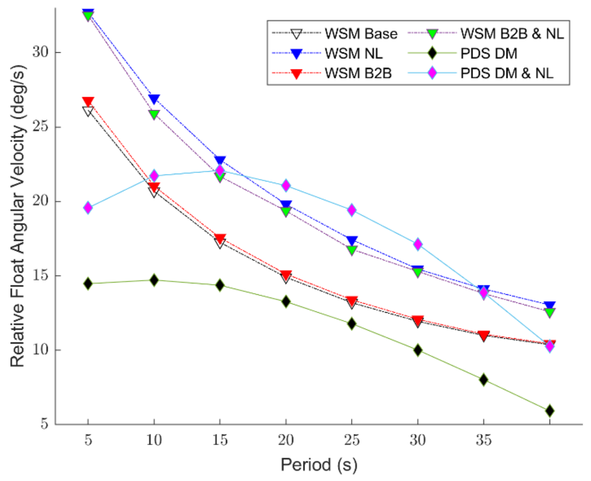
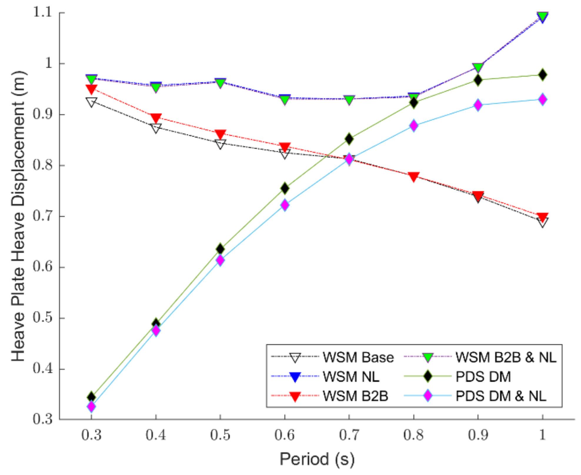
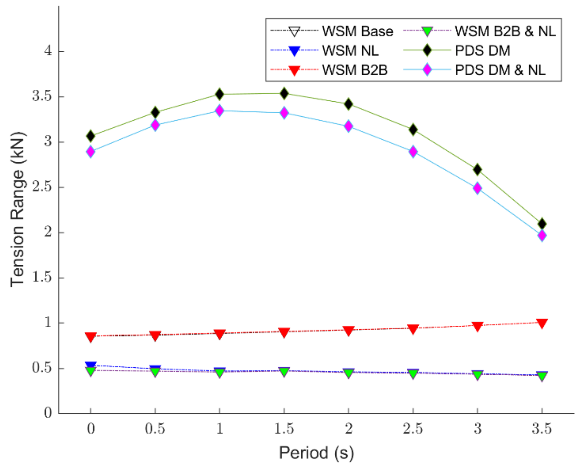
5.1. Code-to-Code Comparison

A code-to-code regular wave comparison highlights the impact of hydrodynamic theory differences in a known and predictable sea state. Combourieu et al. provided a baseline understanding of a WEC’s simulated response in ProteusDS and WEC-Sim by comparing and verifying similar responses of a floating three-body oscillating flap device in different time-domain multibody dynamic modelling software, including WEC-Sim and ProteusDS [1]. Furthermore, Wendt et al. compared and validated the dynamic response of a floating sphere and regular a floating cylinder between numerous WEC numerical modelling software, including WEC-Sim and ProteusDS [3]. The aforementioned studies showed that WEC-Sim and ProteusDS produce highly comparable dynamic responses when utilizing common baseline theories (as described in Section 2.1). As such, this study focuses on the impacts of refined numerical theories through a code-to-code comparison for regular wave scenarios listed in Table 2. Comparison quantities of interest for WEBS are the relative float pitch velocity, the PTO tether tension, and heave plate response.
Relative float angular velocity concerns the WEBS fore float pitching about the nacelle, which houses the PTO, is directly correlated to energy generation. Figure 5 shows the relative float angular velocity oscillation magnitude for the various simulation scenarios.
Including weakly nonlinear Froude-Krylov and hydrostatic force calculations has a clear impact on float response. Specifically, when weakly nonlinear calculations are included, the relative float angular velocity increases. This corresponds to the greater phase difference between the nacelle and fore float with weakly nonlinear terms. Such a phenomenon occurs because the fore float’s dynamic wetted surface area increases variation in F exc and F HP calculations. When comparing WSM Base and WSM NL, the inclusion of weakly nonlinear Froude-Krylov and Hydrostatic force calculations is found to increase the relative float angular velocity by an average of 29% over the specified wave frequency range. These findings align with Michele et al. [22], whom find that with the implementation of weakly nonlinear forces, extractable energy increases due to increased float motion.
B2B interactions do not have a significant impact on WEBS dynamics. When comparing WSM Base to WSM B2B or WSM NL to WSM B2B and NL, the relative float angular velocity magnitude changes only slightly. When comparing WSM Base and WSM B2B, the inclusion of B2B interactions alters the relative float angular velocity by an average of 1% over the specified wave frequency range. The small impact of B2B interactions may be due to the joint connection between bodies for the WEBS three-part float. Therefore, B2B interactions may still be of importance for rigid bodies in an array as discussed in Starrett et al. [27].
Cable model fidelity has a direct impact on WEC dynamics. Figure 5 shows that all scenarios modelling the tether with a simplified spring have an inverse relationship with wave period. A heave plate helps a WEC capture resonance within a particular frequency range [51]. The simplified spring cable’s unable to capture resonance, for motion only increases with decreasing wave period. Therefore, the heave plate’s load is not being transferred to the WEC’s float through the tether. When the tether is more realistically modelled with a dynamic cable model, the float angular velocity oscillation magnitude increases toward a resonance condition and then decreases. Therefore, the heave plate load is transferred to the WEC’s float. The trend difference hinders the determination of a clear quantitative value that a dynamic cable model has on the relative float angular velocity. However, dynamic cable modelling does improve the model’s ability to capture peak energy extraction, for the resonance condition matches the design sea state’s energy period of 7.9 s. Dynamic cable calculations are shown to directly correspond with the WEC’s ability to capture resonance around the design sea state.
The PTO tether connects the hydrodynamically active surface float to the heave plate and plays an important role in the hydrodynamic modelling and the design process. Tension range displays the WEC’s load variability due to wave forcing.
As shown in Figure 6 the inclusion of weakly nonlinear calculations reduces tether tension range. This differs from WEBS float motion magnitude, as seen in Figure 5. Recall from Figure 2, weakly nonlinear calculations are dependent on both wave frequency and the extent to which the mesh is submerged (rather than wave frequency alone as with linear calculations). From Equation (2) and Equation (4), F exc and F HP terms are smaller with increased rigid body submergence, and these smaller terms correspond to smaller WEC loads. For WEBS, the nacelle, which attaches to the PTO tether, is continually submerged, so weakly nonlinear calculations formulate a smaller WEC load and therefore a smaller tether tension range as shown in Figure 6. The inclusion of weakly nonlinear Froude-Krylov and hydrostatic force calculations is found to decrease tether tension range by an average of 48% through comparisons between WSM Base to WSM NL.
B2B interactions are not shown to impact tether tension. Cable tension is directly related to WEC loads. Figure 6 displays that B2B interactions have little impact on tether tension loads, which agrees with Figure 5 that showed B2B interactions have little impact on WEBS dynamics. Specifically, when comparing WSM Base to WSM B2B, a 0.3% increase in tension range is computed.
When implementing dynamic cable theories, WEBS experiences a significantly larger tension range. Tension with a simplified spring model follows Hooke’s law, and has a fairly small and consistent range across varying wave periods. By implementing a dynamic cable theory, tether tension range varies significantly. When comparing WSM Base to PDS DM, modelling with a dynamic cable model increases tether tension range by an average of 240%. The larger range in dynamic cable model scenarios is in part due to the numerical model’s inclusion of an axial stiffness term. Axial stiffness is directly related to strain, and tension grows linearly with strain [39]. Additionally, with dynamic cable models, tether tension ranges in Figure 6 follow similar trends with wave period as shown for the WEC’s float motion in Figure 5. As such, the larger tension ranges in dynamic cable models correspond to larger WEC loads.
Heave plates play a key role in WEC dynamics and PTO efficiency, and provide a reaction force from the relatively stationary water deep below the WEC [39,44]. The heave displacement of a heave plate is directly correlated to how well the heave plate is performing as an artificial seafloor.
Weakly nonlinear Froude-Krylov and hydrostatic calculations and not implemented for the heave plate for any scenario, for it is 60 m deep and does not have a dynamic wetted surface area. However, weakly nonlinear terms at the surface do influence heave plate displacement. They are shown to decrease heave plate displacement when coupled with dynamic cable models, but increase heave plate displacement when the tether is modelled with a simplified spring. Recall from Figure 6 that tether tension does not vary significantly when utilizing a spring cable model. Thus, focusing on scenarios PDS DM and PDS DM and NL, the heave plate displacement magnitude decreases due with weakly nonlinear Froude-Krylov and hydrostatic calculations. Comparisons between PDS DM and PDS DM and NL show that the inclusion of weakly nonlinear Froude-Krylov and hydrostatic force calculations decreases heave plate displacement by an average of 4%. This finding confirms Figure 6, which showed tether loads decreased with the inclusion of weakly nonlinear terms.
B2B interactions are shown to not play a significant role in heave plate displacement. Comparisons between WSM Base and WSM B2B show that the inclusion of B2B interactions alters heave plate displacement by an average of 1%. This result is consistent with B2B theory, for the heave plate is far away from any other rigid body, so B2B interactions are presumably negligible.
The utilization of dynamic cable models significantly affects the heave plate response. When included, displacement increases with wave period. This is because with an increasing wave period there is a decreasing phase difference between the heave plate’s and wave elevation’s oscillations, which increases overall oscillation size. When the tether is modelled with a simplified spring cable, the heave plate’s oscillation does not change with wave period, and is due to the inaccuracy in the transfer of loads from the surface to the heave plate. As in Figure 5, the trend difference with cable modelling approaches prevent clear quantitative heave plate depth in Figure 7.

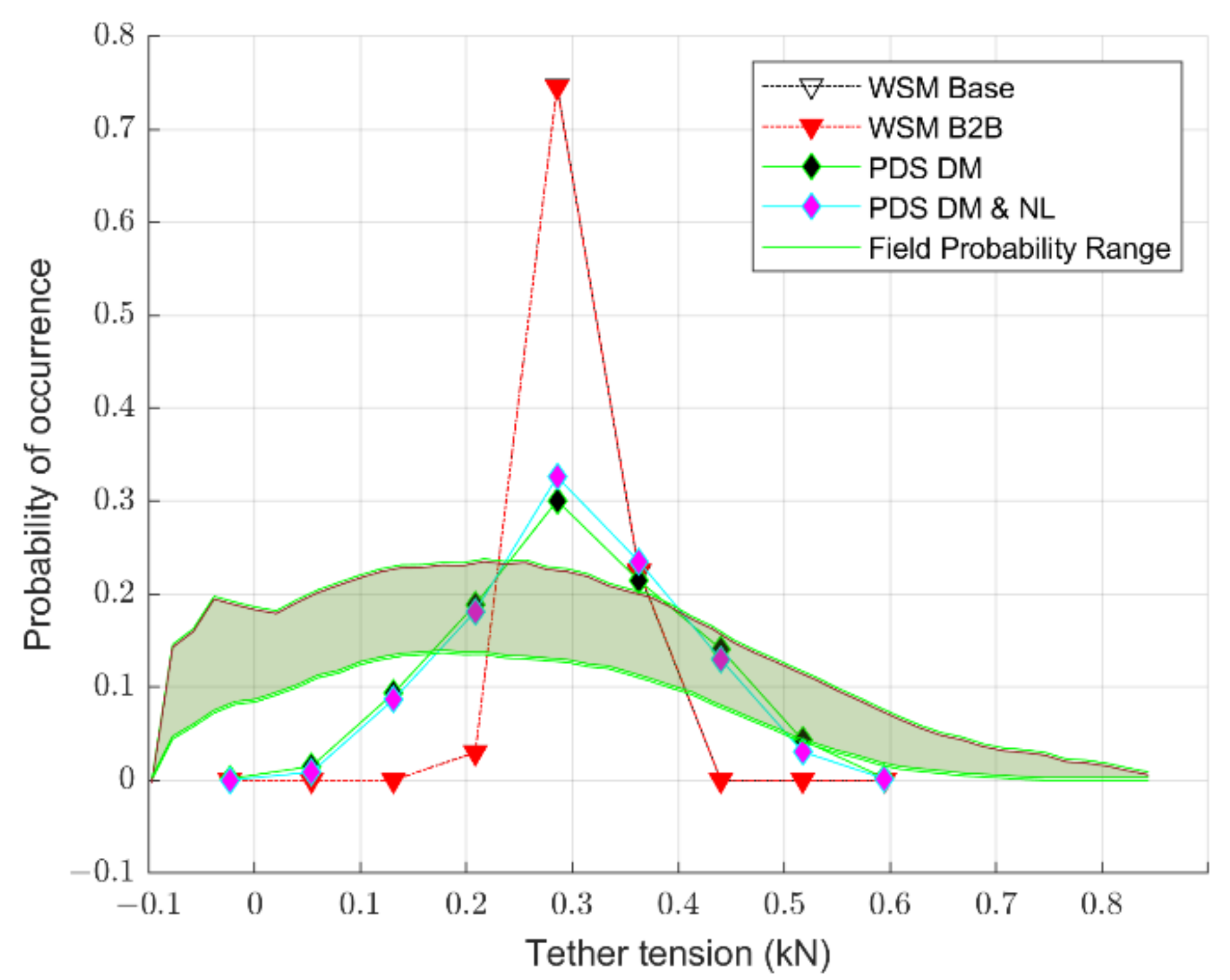
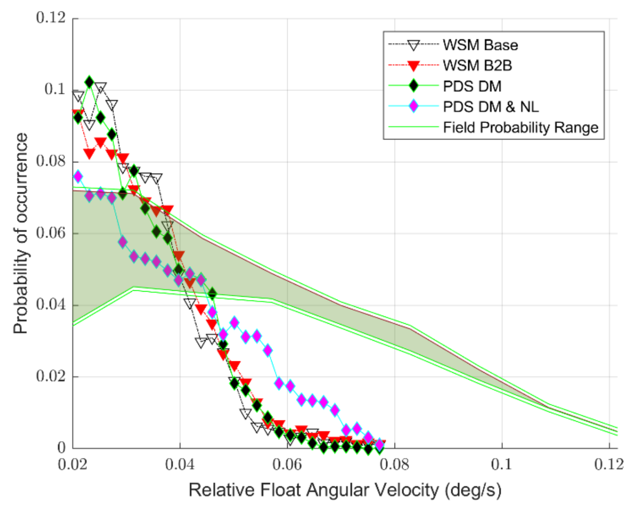
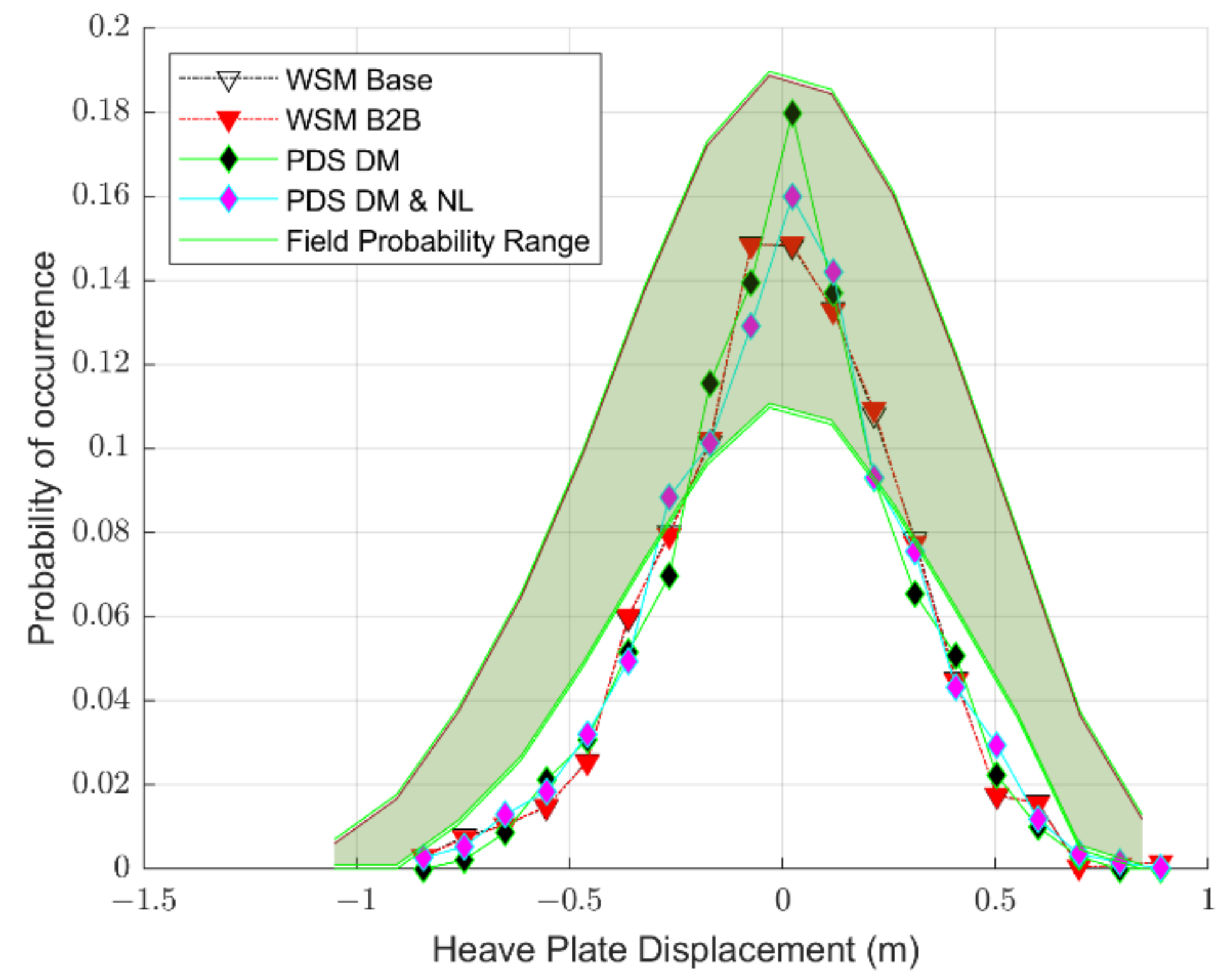
5.2. Code-to-Field Campaign Comparison

The code-to-field campaign comparison uses the 448 s wave data from SWIFT buoys for simulating WEBS numerically and validating simulations. Wave reconstruction methods as discussed in Section 4.2 are implemented in this code-to-field comparison. However, weakly nonlinear calculations are not permissible when importing a time series, for weakly nonlinear calculations require the wave induced pressure at each wetted mesh panel [40]. Therefore, an imported time-series in WEC-Sim scenarios that utilize weakly nonlinear Froude-Krylov and hydrostatic calculations would not work, as the rigid bodies begin at the mean water surface elevation as shown in Figure 2a, and there would be disparities present in rigid body position relative to the instantaneous surface elevation [40]. PDS DM and NL is capable of simulating the wave-reconstructed wavefield, for the wave elevation time-series is developed from the frequency domain in the ProteusDS solver. Therefore, only the WSM Base, WSM B2B, PDS DM, and PDS DM and NL scenarios are simulated for wave reconstruction simulations. Comparisons between PDS DM and PDS DM and NL scenarios will show the impact weakly nonlinear Froude-Krylov and hydrostatic calculations has on WEC dynamics, and so this study is still able to validate the relative impact of all the refined numerical theories discussed in Section 2.2.
The WEBS field data is represented by the shaded green region in Figure 8, Figure 9 and Figure 10 and is based on the probability of occurrence for each 448 s segment of the 8 h WEBS field data.
Float angular velocity is directly proportional to WEBS extractable energy calculations. It is clear from Figure 8 that the maximum float angular velocity is underpredicted regardless of refined numerical theory implemented. The underpredictions can be attributed to: (1) inaccuracies in modelling calculation, or (2) the inability of the reconstructed wave field to formulate waves as large as those experienced during the WEBS field campaign due to the wave reconstruction’s reliance on regular wave superposition. Particularly, the regular wave superposition approximation involved with the chosen wave reconstruction methodology is unable to produce steep, higher order waves that occur in the field, as per Whitmer et al. [52].
Simulated float angular velocity increases with weakly nonlinear Froude-Krylov and hydrostatic terms, and more closely resembles the float angular velocity experienced in the field. Furthermore, the shifting trend past 5 deg/s for the PDS DM and NL scenario is due to the increased relative rotational velocity between the nacelle and the fore float when employing weakly nonlinear Froude-Krylov and hydrostatics to the numerical model. These findings validate the code-to-code results discussed in Section 5.1. B2B interactions slightly increase float angular velocity, but this difference is small and could be attributed to slight computational differences. Dynamic cable modelling is not shown to play a significant role in simulation accuracy for the surface float’s motion, as Figure 8 displays that WSM Base and PDS DM have similar float angular velocity probability ranges. The representation used in Figure 8 underrepresents the differences due to dynamic cable modelling. Figure 5 shows that relative float angular velocity differences due to cable modelling scheme depend significantly on wave frequency. Specific wave conditions are not shown in Figure 8, and so the impact due to dynamic cable modelling is not clearly represented.
Tether tension indicates how well the numerical methods model captures the WEC loads. As with float angular velocity, tether tension is underpredicted regardless of numerical approach, as shown in Figure 9. PDS DM experiences the largest simulated tension range with extreme tension values under 2 kN and over 6 kN. In the field campaign, the 5th and 95th tether tension percentiles are 0.5 kN and 6.6 kN, respectively [47]. Therefore, the majority of the tensions experienced during the WEBS field campaign are met, but the more extreme loads are not captured. The tether tension underprediction may be a result of loading heave plate hydrodynamics from BEM software, for this method provides smaller hydrodynamic resistance than experimental data, as per Rusch et al. [53].
The inclusion of weakly nonlinear Froude-Krylov and hydrostatic terms slightly impacts the tether range. The linear approach with PDS DM experiences a slightly larger range than PDS DM and NL, which confirms Figure 6. Additionally, the inclusion of B2B interactions does not impact tether tension, for WSM B2B completely overlaps WSM Base as shown in Figure 6. It is clear from Figure 9 that the static spring cable model has a much smaller tension range than experienced by dynamic mooring calculations. This is expected, as Figure 6 showed that with the static spring approach tether tension range is invariant with wave frequency. Dynamic cable models significantly increase the fidelity in capturing the cable’s structural dynamics, and provide a better representation of tension and final power production.
Heave plate displacement indicates how well the numerical scenarios capture the WEC dynamics far away from the surface, which is 60 m for WEBS. In Figure 10, the numerical model heave displacement data is superimposed with surface elevation to ensure consistency with the field data.
Weakly nonlinear Froude-Krylov and hydrostatic forces do not have a clear impact on the heave plate displacement, for displacement probabilities in PDS DM and PDS DM and NL consistently overlap one another. However, the linear calculations of PDS DM has a 2% larger probability of a minimum displacement of 0 m than PDS DM and NL. In Figure 5 and Figure 8, we found an increase in float angular velocity with the inclusion of weakly nonlinear terms. This increase in the WEC’s float motion corresponds to a more dynamic heave plate response. Therefore, the 2% difference due to the inclusion of weakly nonlinear terms is expected. B2B interactions are shown to not impact heave plate dynamics in Figure 10. This insignificance, matches what we saw in Figure 7 and found in Section 5.1. The heave plate is far away from any other rigid body, thereby making inter-body coefficients miniscule or nonexistent. Finally, dynamic mooring calculations are not shown to significantly impact heave plate displacement accuracy. Regardless of chosen numerical theories implementation, the rigid body dynamics appear well-captured.

6. Conclusions

This study’s objectives concern: quantifying how the incorporation of weakly nonlinear Froude-Krylov and hydrostatic calculations, body-to-body interactions, and/or dynamic cable computations impact a WEC’s dynamics; and validating the performance of these numerical simulations against field measurement data.
Utilizing a case study WEC and field deployment data from the WEBS field campaign and SWIFT buoy data, these refined hydrodynamic theories were verified and validated. It is well understood that multibody WEC dynamics are highly intermingled and inter-related. Therefore, this study quantifies the impact of each refined hydrodynamic theory to better understand theoretical significance in WEC dynamics.
Weakly nonlinear Froude-Krylov and hydrostatic calculations are shown to significantly increase the float motion of a WEC, and therefore increase extractable energy. For the regular wave tests performed in the WEBS case study, the inclusion of weakly nonlinear Froude-Krylov and hydrostatic terms increase the fore float’s relative angular velocity about the nacelle by a maximum of 29% when the simulations also use a static spring cable model, and by a maximum of 54% with dynamic cable models. Weakly nonlinear Froude-Krylov and hydrostatic calculations have a clear impact on WEC dynamics, and the relative impact of this theory is dependent on additional refined hydrodynamic modelling techniques.
B2B interactions were negligible in this study. For the regular wave tests performed in the WEBS case study, the inclusion of B2B interactions changed the fore float’s relative angular velocity about the nacelle by less than 5%. However, the small impact of B2B interactions may be due to the particular WEC’s joint, which connects rigid bodies at the surface.
Dynamic cable modelling is shown to significantly impact the overall performance of a WEC. Particularly, dynamic cable models are shown to improve the simulated capacity to capture resonance around the design sea state as discussed in Section 5.1. Furthermore, with dynamic cable models, tether tension range increases by 300%, thereby showing significantly more variability in simulating WEC loads due to wave forcing.
This research highlights the continued need for future investigation on the impact of differing hydrodynamic theories, particularly, for floating wave energy converters. Specifically, the impact of B2B interactions may be examined for WEC systems with numerous disconnected but closely situated rigid bodies. Furthermore, incorporating more realistic waves into the numerical wave field through wave reconstruction or nonlinear wave methods provide an improved ability to do code-to-field data comparative fidelity.
Both rigid body hydrodynamics and cable dynamics must be well-represented to ensure accurate WEC modelling. Implementing refined hydrodynamic theories into a WEC numerical model may significantly improve simulation accuracy. This study found: (1) that simulating body-to-body interactions did not alter WEC dynamics, and (2) that the inclusion of weakly nonlinear Froude-Krylov and hydrostatic force terms and dynamic cable models within a numerical model significantly improve simulated WEC dynamics.

Author Contributions

Conceptualization, M.L. and B.R.; methodology, M.L.; formal analysis, M.L.; investigation, M.L.; writing—original draft preparation, M.L.; writing—review and editing, C.R., Z.Z. and B.R.; supervision, C.R., Z.Z. and B.R.; project administration, B.R.; funding acquisition, B.R. All authors have read and agreed to the published version of the manuscript.

Funding

This research was funded by the U.S. Department of Defense award number: N0002410D6318/N0002419F8709.

Acknowledgments

The authors would like to thank all personnel involved with the WEBS campaign. Furthermore, the authors would like to thank the personnel from PRIMED for assisting in the wave reconstruction techniques performed. M. Leary would also like to acknowledge Bret Bosma for modelling guidance and support.

Conflicts of Interest

The authors declare no conflict of interest.

References

  1. Combourieu, A.; Lawson, M.; Babarit, A.; Ruehl, K.; Roy, A.; Costello, R.; Laporte-Weywada, P.; Bailey, H. WEC3: Wave Energy Converter Code Comparison Project. In Proceedings of the 11th European Wave and Tidal Energy Conference (EWTEC2015), Nantes, France, 6–11 September 2015; pp. 1–10. [Google Scholar]
  2. Newman, J.N. Marine Hydrodynamics; The MIT Press: Cambridge, UK, 2018. [Google Scholar]
  3. Wendt, F.; Nielsen, K.; Yu, Y.-H.; Bingham, H.; Eskilsson, C.; Kramer, M.; Babarit, A.; Bunnik, T.; Costello, R.; Crowley, S.; et al. Ocean Energy Systems Wave Energy Modelling Task: Modelling, Verification and Validation of Wave Energy Converters. J. Mar. Sci. Eng. 2019, 7, 379. [Google Scholar] [CrossRef] [Green Version]
  4. Starrett, M.; So, R.; Brekken, T.K.; McCall, A. Development of a state space model for wave energy conversion systems. In Proceedings of the 2015 IEEE Power & Energy Society General Meeting, Denver, CO, USA, 26–30 July 2015; pp. 1–5. [Google Scholar] [CrossRef]
  5. Davidson, J.; Ringwood, J.V. Mathematical Modelling of Mooring Systems for Wave Energy Converters—A Review. Energies 2017, 10, 666. [Google Scholar] [CrossRef] [Green Version]
  6. Paduano, B.; Giorgi, G.; Gomes, R.P.F.; Pasta, E.; Henriques, J.C.C.; Gato, L.M.C.; Mattiazzo, G. Experimental Validation and Comparison of Numerical Models for the Mooring System of a Floating Wave Energy Converter. J. Mar. Sci. Eng. 2020, 8, 565. [Google Scholar] [CrossRef]
  7. Zhao, X.; Xue, R.; Geng, J.; Göteman, M. Analytical investigation on the hydrodynamic performance of a multi-pontoon breakwater-WEC system. Ocean Eng. 2021, 220, 108394. [Google Scholar] [CrossRef]
  8. Pastor, J.; Liu, Y. Frequency and time domain modeling and power output for a heaving point absorber wave energy converter. Int. J. Energy Environ. Eng. 2014, 5, 1–13. [Google Scholar] [CrossRef] [Green Version]
  9. Bailey, H.; Ortiz, J.P.; Robertson, B.; Buckhamn, B.J.; Nicoll, R.S. A Methodology for Wave-to-Wire WEC Simulations. In Proceedings of the 2nd Marine Energy Technology Symposium, Seattle, WA, USA, 15–18 April 2014; pp. 1–15. Available online: https://vtechworks.lib.vt.edu//handle/10919/49238 (accessed on 22 February 2021).
  10. Robertson, B.; Bailey, H.; Leary, M.; Buckham, B. A methodology for architecture agnostic and time flexible representations of wave energy converter performance. Appl. Energy 2021, 287, 116588. [Google Scholar] [CrossRef]
  11. Windt, C.; Davidson, J.; Ringwood, J.V. High-fidelity numerical modelling of ocean wave energy systems: A review of computational fluid dynamics-based numerical wave tanks. Renew. Sustain. Energy Rev. 2018, 93, 610–630. [Google Scholar] [CrossRef] [Green Version]
  12. Yeylaghi, S.; Beatty, S.; Crawford, C.; Oshkai, P.; Buckham, B.; Moa, B. SPH Modeling of Hydrodynamic Loads on a Point Absorber Wave Energy Converter Hull. In Proceedings of the 11th European Wave and Tidal Energy Conference (EWTEC2015), Nantes, France, 6–11 September 2015; pp. 1–7. [Google Scholar]
  13. Coe, R.G.; Bull, D.L. Nonlinear time-domain performance model for a wave energy converter in three dimensions. In Proceedings of the 2014 Oceans-St. John’s, St. John’s, NL, Canada, 14–19 September 2014; pp. 1–10. [Google Scholar] [CrossRef]
  14. Ahamed, R.; McKee, K.; Howard, I. Advancements of wave energy converters based on power take off (PTO) systems: A review. Ocean Eng. 2020, 204, 107248. [Google Scholar] [CrossRef]
  15. Têtu, A. Power Take-Off Systems for WECs. Handbook of Ocean Wave Energy; Springer: New York, NY, USA, 2016; pp. 203–220. [Google Scholar]
  16. Morison, J.; Johnson, J.; Schaaf, S. The Force Exerted by Surface Waves on Piles. J. Pet. Technol. 1950, 2, 149–154. [Google Scholar] [CrossRef]
  17. Bergdahl, L. Mooring Design for WECs. In Handbook of Ocean Wave Energy; Springer: New York, NY, USA, 2016; pp. 159–202. [Google Scholar]
  18. Lee, J.N.; Newman, C.H. Wamit User Manual; WAMIT, Inc.: Chestnut Hill, MA, USA, 2006; p. 42. [Google Scholar]
  19. Anderson, E. Application of the Open Source Code Nemoh for Modelling of Added Mass and Damping in Ship Motion Simulations. 2018. Available online: http://urn.kb.se/resolve?urn=urn:nbn:se:kth:diva-239044 (accessed on 27 March 2021).
  20. Penalba, M.; Giorgi, G.; Ringwood, J.V. Mathematical modelling of wave energy converters: A review of nonlinear approaches. Renew. Sustain. Energy Rev. 2017, 78, 1188–1207. [Google Scholar] [CrossRef] [Green Version]
  21. Davidson, J.; Costello, R. Efficient Nonlinear Hydrodynamic Models for Wave Energy Converter Design—A Scoping Study. J. Mar. Sci. Eng. 2020, 8, 35. [Google Scholar] [CrossRef] [Green Version]
  22. Michele, S.; Sammarco, P.; D’Errico, M. Weakly nonlinear theory for oscillating wave surge converters in a channel. J. Fluid Mech. 2017, 834, 55–91. [Google Scholar] [CrossRef] [Green Version]
  23. Penalba-Retes, M.; Mérigaud, A.; Gilloteaux, J.C.; Ringwood, J. Nonlinear Froude-Krylov force modelling for two heaving wave energy point absorbers. In Proceedings of the 11th European Wave and Tidal Energy Conference (EWTEC2015), Nantes, France, 6–11 September 2015; pp. 1–10. [Google Scholar]
  24. Wheeler, J. Method for Calculating Forces Produced by Irregular Waves. J. Pet. Technol. 1970, 22, 359–367. [Google Scholar] [CrossRef]
  25. Lo, J.-M.; Dean, R.G. Evaluation of a Modified Stretched Linear Wave Theory. In Coastal Engineering; ACSE: Reston, VA, USA, 1986; pp. 522–536. [Google Scholar]
  26. Tom, N.; Lawson, M.; Yu, Y.-H. Demonstration of the Recent Additions in Modeling Capabilities for the WEC-Sim Wave Energy Converter Design Tool. American Society of Mechanical Engineers Digital Collection. In Proceedings of the ASME 2015 34th International Conference on Ocean, Offshore and Arctic Engineering, St. John’s, NL, Canada, 31 May–5 June 2015; ASME International: St. John’s, NL, Canada, 2015; Volume 9, pp. 1–11. [Google Scholar]
  27. Starrett, M.; So, R.; Brekken, T.K.; McCall, A. Increasing power capture from multibody wave energy conversion systems using model predictive control. In Proceedings of the 2015 IEEE Conference on Technologies for Sustainability (SusTech), Ogden, UT, USA, 30 July–1 August 2015; pp. 20–26. [Google Scholar] [CrossRef]
  28. Sigrist, J.-F. Fluid-Structure Interaction: An Introduction to Finite Element Coupling; John Wiley & Sons: Hoboken, NJ, USA, 2015. [Google Scholar]
  29. Buckham, B.J. Dynamics Modelling of Low-Tension Tethers for Submerged Remotely Operated Vehicles. Ph.D. Thesis, University of Victoria, Victoria, Canada, 2003. [Google Scholar]
  30. Walton, T.S.; Polachek, H. Calculation of Transient Motion of Submerged Cables. Math. Comput. 1960, 14, 27–46. [Google Scholar] [CrossRef]
  31. Reid, R.O. Dynamics of Deep-Sea Mooring Lines; Department of Oceanography; Texas A and M University: College Station, TX, USA, 1968. [Google Scholar]
  32. Hicks, J.B.; Clark, L.G. On the Dynamic Response of Buoy-Supported Cables and Pipes to Currents and Waves. All Days 1972, 30. [Google Scholar] [CrossRef]
  33. Hall, M.; Goupee, A. Validation of a lumped-mass mooring line model with DeepCwind semisubmersible model test data. Ocean Eng. 2015, 104, 590–603. [Google Scholar] [CrossRef] [Green Version]
  34. Huang, S. Dynamic analysis of three-dimensional marine cables. Ocean Eng. 1994, 21, 587–605. [Google Scholar] [CrossRef]
  35. Triantafyllou, M.; Howell, C. Dynamic Response of Cables Under Negative Tension: An Ill-Posed Problem. J. Sound Vib. 1994, 173, 433–447. [Google Scholar] [CrossRef]
  36. Ferri, F.; Palm, J. Implementation of a Dynamic Mooring Solver (MOODY) into a Wave to Wire Model of a Simple WEC; Department of Civil Engineering; Aalborg University: Aalborg, Denmark, 2015. [Google Scholar]
  37. Triantafyllou, M.S.; Howell, C.T. Nonlinear Impulsive Motions of Low Tension Cables. J. Eng. Mech. 1992, 118, 807–830. [Google Scholar] [CrossRef]
  38. Buckham, B.; Driscoll, F.R.; Nahon, M. Development of a Finite Element Cable Model for Use in Low-Tension Dynamics Simulation. J. Appl. Mech. 2004, 71, 476–485. [Google Scholar] [CrossRef]
  39. DSA, L. Dynamic Systems Analysis, ProteusDS Manual. 2015. Available online: http://http://downloads.dsa-ltd.ca/documentation/ProteusDS%202015%20Manual.pdf (accessed on 12 July 2020).
  40. WEC-Sim. Version 4.2. 2014. Available online: http://en.openei.org/wiki/WECSim (accessed on 27 March 2021).
  41. Systèmes, D.; Corporation, S.; Street, W. SOLIDWORKS Mold Design Using SOLIDWORKS. 1995. Dassault Systèmes Solidworks Corportation, Waltham, MA, USA. Available online: https://www.solidworks.com/ (accessed on 1 July 2020).
  42. McNeel, R. Rhinoceros User Guide. 2020. Available online: http://docs.mcneel.com/rhino/6/usersguide/en-us/index.htm (accessed on 15 March 2021).
  43. McTaggart, K. ShipMo3D Version 3.0 User Manual for Computing Ship Motions in the Time and Frequency Domains; DRDC Atlantic TM 2011-308; Atlantic Research Centre: Dartmouth, NS, Canada, 2011. [Google Scholar]
  44. Babarit, A.; Delhommeau, G. Theoretical and numerical aspects of the open source BEM solver NEMOH. In Proceedings of the 11th European Wave and Tidal Energy Conference (EWTEC2015), Nantes, France, 6–11 September 2015; pp. 1–12. [Google Scholar]
  45. DSA, L. Dynamic Systems Analysis, ProteusDS API Manual. 2017. Available online: http://downloads.dsa-ltd.ca/documentation/ProteusDS_API_Manual.pdf (accessed on 22 February 2021).
  46. Hall, M. “MoorDyn User’ s Guide,” Manual. 2017. Available online: http://www.matt-hall.ca/files/MoorDyn-Users-Guide-2017-08-16.pdf (accessed on 15 March 2021).
  47. Rusch, C.J. Wave Energy Buoy the Self-Deploys; Pacific Marine Energy Center: Seattle, WA, USA, 2021; pp. 1–23. Available online: https://www.pmec.us/technical-reports (accessed on 22 April 2021).
  48. Thomson, J. Wave Breaking Dissipation Observed with “SWIFT” Drifters. J. Atmos. Ocean. Technol. 2012, 29, 1866–1882. [Google Scholar] [CrossRef]
  49. Korde, U.A.; Robinett, R.D.; Wilson, D.G.; Bacelli, G.; Abdelkhalik, O.O. Wave-by-Wave Control of a Wave Energy Converter with Deterministic Wave Prediction. In Proceedings of the European Wave and Tidal Energy Conference (EWTEC2017), Cork, Ireland, 27 August–1 September 2017; pp. 1–10. [Google Scholar]
  50. Fisher, A.; Thomson, J.; Schwendeman, M. Rapid deterministic wave prediction using a sparse array of buoys. Ocean Eng. 2021, 228, 108871. [Google Scholar] [CrossRef]
  51. Davis, A.F.; Thomson, J.; Mundon, T.R.; Fabien, B.C. Modeling and Analysis of a Multi Degree of Freedom Point Absorber Wave Energy Converter. In Proceedings of the 33rd International Conference on Ocean, Offshore and Arctic Engineering, San Francisco, CA, USA, 8–13 June 2014; pp. 1–10. [Google Scholar] [CrossRef] [Green Version]
  52. Whitmer, A.R.; Klamo, J.T.; Kwon, Y.W. On the Validity of Predicting Wave-induced Loads on a Submerged Body Using the Superposition of Regular Wave Results. In Proceedings of the Oceans 2019 MTS/IEEE Seattle, Seattle, WA, USA, 27–31 October 2019. [Google Scholar] [CrossRef]
  53. Rusch, C.J.; Mundon, T.R.; Maurer, B.D.; Polagye, B.L. Hydrodynamics of an asymmetric heave plate for a point absorber wave energy converter. Ocean Eng. 2020, 215, 107915. [Google Scholar] [CrossRef]
Figure 1. Wave Energy Converter numerical modelling fidelity ranking.
Energies 14 03959 g001
Figure 2. Nonlinear Froude-Krylov and Hydrostatic force meshing dependency. (a) Linear calculations with constant coefficients, (b) Weakly nonlinear calculations with instantaneous surface elevation dependent coefficients.
Energies 14 03959 g002
Figure 3. WEC numerical modelling procedure from creating a geometric build to implementating into a time-domain multibody dynamic model.
Energies 14 03959 g003
Figure 4. Wave Energy Buoy that Self-deploys WEC device as deployed (tether length not to scale) [47].
Energies 14 03959 g004
Figure 5. WEBS relative float angular velocity oscillation magnitude in regular waves.
Energies 14 03959 g005
Figure 6. WEBS tether tension range in regular waves.
Energies 14 03959 g006
Figure 7. Maximum WEBS heave place heave displacement in regular waves.
Energies 14 03959 g007
Figure 8. WEBS wave reconstruction regular float angular velocity probability.
Energies 14 03959 g008
Figure 9. WEBS wave reconstruction tether tension probability of occurrence.
Energies 14 03959 g009
Figure 10. WEBS wave reconstruction heave plate displacement.
Energies 14 03959 g010
Table 1. Wave Energy Buoy that Self-deploys Viscous Drag Coefficients for a z-vertical coordinate system.
Rigid BodyCDxCDyCDz
Aft Float11.91
Fore Float11.91
Nacelle111
Heave Plate1.41.44.5
Table 2. Refined numerical theories scenarios (WSM: WEC-Sim, PDS: ProteusDS; X = Theory in-cluded).
Modelling ScenarioTheory
Weakly Nonlinear (NL)Body-to-Body Interactions (B2B)Dynamic Cables (DM)
WSM Base
WSM NLX
WSM B2B X
WSM B2B and NLXX
PDS DM X
PDS DM and NLX X
Publisher’s Note: MDPI stays neutral with regard to jurisdictional claims in published maps and institutional affiliations.

