Article

Improved Immune Algorithm Combined with Steepest Descent Method for Optimal Design of IPMSM for FCEV Traction Motor

1
Department of Electrical, Electronic and Computer Engineering, University of Ulsan, Ulsan 44610, Korea
2
Korea Electrotechnology Research Institute, Changwon-si 51543, Korea
*
Author to whom correspondence should be addressed.
Energies 2021, 14(13), 3904; https://doi.org/10.3390/en14133904
Submission received: 10 May 2021 / Revised: 7 June 2021 / Accepted: 26 June 2021 / Published: 29 June 2021
(This article belongs to the Special Issue Advanced Techniques for High-Performance Permanent Magnet Motors)

Abstract

:
In this paper, an improved immune algorithm (IIA) was proposed for the torque ripple reduction optimal design of an interior permanent magnet synchronous motor (IPMSM) for a fuel cell electric vehicle (FCEV) traction motor. When designing electric machines, both global and local solutions of optimal designs are required as design result should be compared in various aspects, including torque, torque ripple, and cogging torque. To lessen the computational burden of optimization using finite element analysis, the IIA proposes a method to efficiently adjust the generation of additional samples. The superior performance of the IIA was verified through the comparison of optimization results with conventional optimization methods in three mathematical test functions. The optimal design of an IPMSM using the IIA was conducted to verify the applicability in the design of practical electric machines.

1. Introduction

Globally, regulations on carbon dioxide emissions are strengthening, and the demand for zero-emission vehicles is increasing. Fuel cell electric vehicles (FCEVs) are a good alternative to internal combustion engine vehicles, since they do not have exhaust gas and have a shorter charging time than battery electric vehicles [1]. The performance of the traction motor is crucial for FCEVs, as the vehicle is driven only by a motor. Therefore, both high power density and high efficiency are required for the traction motor. The interior permanent magnet synchronous motor (IPMSM) seems to be suitable, as it has a high torque density, power factor, and a wide operating range [2,3,4,5]. For the ride comfort of FCEV traction motors, reducing torque ripple is important as it causes noise and vibration of the vehicle [6,7,8]. Torque ripple of the IPMSM can be adjusted with structure design, such as a magnet array [9,10]. Therefore, an optimal design is required to relieve torque ripple.
When analyzing the characteristics of the IPMSM, finite element analysis (FEA) is required, as the IPMSM has nonlinear magnetic saturation. However, the FEA has the problem of high computational cost, especially when it is combined with the optimization of a complex objective region such as multi-modal problem including several solutions. To handle such problem, this paper proposed the improved immune algorithm (IIA).
To reduce the number of function calls, the IIA utilizes the surrogate model. The IIA can deduce the provisional solutions with the interpolated problem region without additional function calls. In addition, an effective search is possible with the selective-filling blank method (S-FBM), which generates mutations far from existing samples and avoids duplicated search in the antibody region. The convergence accuracy of the IIA is also enhanced with combination of the steepest descent method (SDM), which is one of the deterministic methods.
The outstanding performance of the proposed algorithm was verified in three mathematical functions through comparison with the conventional immune algorithm (IA). In particular, the IIA could reduce the number of function calls to convergence at test function 1 to 3 by 89.96%, 95.20% and 93.26%, respectively. Furthermore, the IIA was applied to an optimal design of the IPMSM, and successfully derived the optimal design with reduced torque ripple.

2. Proposed Algorithm

The IA is one of the heuristic optimization algorithms, which is based on the immune system that produces antibodies against invading antigens and excludes antigens. The IA has the following features compared to other optimization algorithms.
  • To ensure the convergence to the optimal solution, optimization is performed with a memory cell. The memory cell group is composed of the superior entities among the population for each iteration.
  • The IA has an affinity calculation process for realizing the diversity of the immune system. There are two kinds of affinity in the IA. One is the antigen-antibody affinity and the other is the antibody-antibody affinity. The antigen-antibody affinity indicates the objective function value. The antibody-antibody affinity is a criterion for evaluating mutual similarity. It can be calculated as:
    affab = 1/(1 + dista,b)
    where affab is the antibody-antibody affinity between entity a and b, and dista,b is the distance between two entities. Among the memory cell that converges to the same solution, only the best one survives, and the rest are removed. With antibody-antibody affinity, the global solution and local solutions can be simultaneously searched.
  • With the expectation concept, the generation of the new antibody can be automatically adjusted. The expectation of the antibody i is defined as:
    ei = affi/ci
    where affi is the antigen-antibody affinity and ci is the concentration. ci can be calculated by dividing the number of similar entities by the total number of entities. The expectation prevents the excessive generation of new antibodies around the solutions, which are regarded as global or local solutions.
With these features, IA shows superior performance than other heuristic optimization algorithms when applied to multi-modal problems with complex problem region and many local peaks [11]. However, IA also requires many function calls and iterations to satisfy the reliable convergence accuracy. In the case of optimal design using FEA for the analysis of electric machines, reducing such computational cost becomes even more important. Therefore, this paper proposed an optimization algorithm that considerably reduces the number of function calls.
The proposed IIA adopts the memory cell concept to search both global and local solutions. Furthermore, the IIA utilizes the interpolation model, which can mitigate computation time [12]. The IIA can converge to the solutions through memory cell sampling (MCS), which adds samples on the provisional solutions of the surrogate model. Additionally, the ability to search for local solutions can be improved using the S-FBM, which generates samples outside of the antibody region. Finally, SDM, one of the deterministic optimization methods, is applied to the virtual memory cells. As a result, memory cells can converge to actual solutions with fewer function calls compared with other heuristic methods.

2.1. Memory Cell Sampling

The surrogate model has the advantage that it can be constructed with existing samples without additional function calls. Additionally, provisional solutions can be easily obtained by comparing the grid value of interpolated problem region. The left side of Figure 1 shows an example of MCS. The background of Figure 1 is an interpolated problem region with pre-generated samples. The red star represents a provisional solution and even if it is not a real solution, a sample is added on the spot. Then, new surrogate model is constructed using both conventional and additional samples. As the iteration passes, the MCS improves the accuracy of the surrogate model especially near real solutions. Therefore, the MCS can enhance the accuracy of the algorithm and reduce the number of function calls by concentrated sampling.

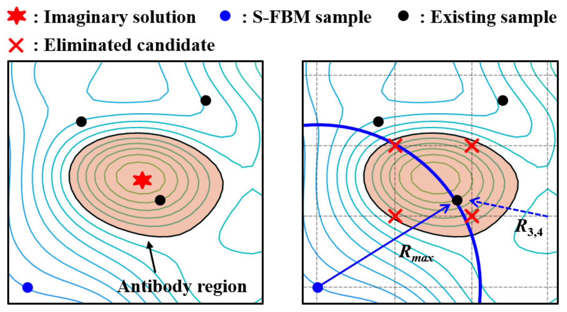
2.2. Antibody Region and Selective-Filling Blank Method

The conventional IA randomly generates mutations throughout the entire problem region. However, such approach has the problem that the problem region can be ununiformly searched [1]. To prevent duplicated searches and to reduce unnecessary function calls, the IIA generates mutations with S-FBM using an antibody region.
Firstly, antibody regions are defined as the region inside of the farthest closed contour near the provisional solutions, and the contour information of the surrogate model can be obtained by the contour function of MATLAB [13]. The antibody region is regarded as a relatively reliable region as the samples are added through the MCS. The antibody region is used as a criterion for selecting candidates for mutations.
The conventional filling blank method generates mutations in the farthest point from the existing samples. The N × M grid points crossing the problem region become candidates of the mutations. The distance from each grid to the closest sample is calculated. The grid point with maximum distance is determined as a mutation as it is the farthest point from the existing samples.
The S-FBM has a process of classifying candidates using an antibody region. To maximize the ability to search missing local solutions, and to navigate the unsearched area efficiently, candidates inside of the antibody region are eliminated. On the right side of Figure 1, the grid points represent the candidates for mutation, and the red “✕” marks are eliminated candidates, as they are located inside of the antibody region. The S-FBM sample or mutation is generated on the blue point, which has the maximum radius among the surviving candidates.

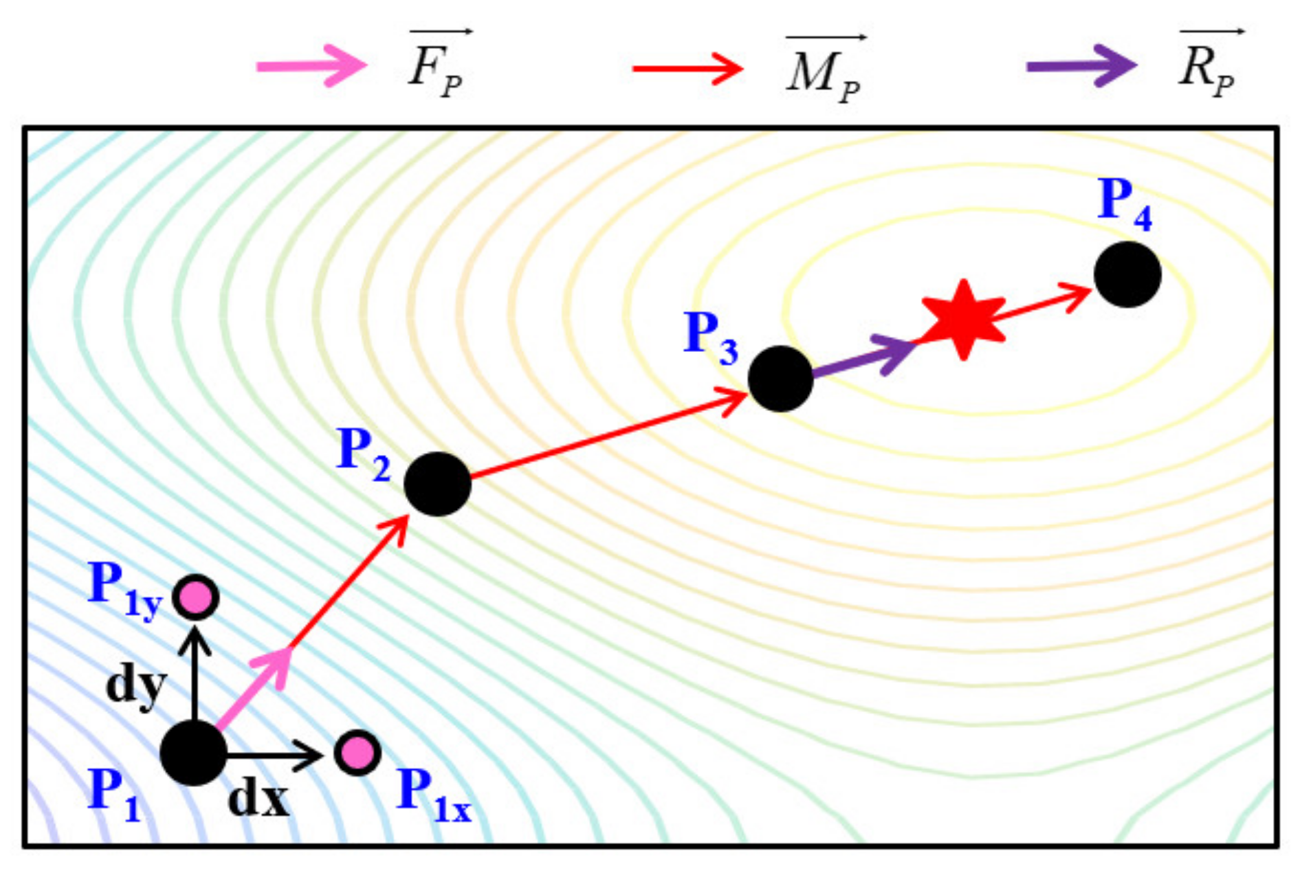
2.3. Steepest Descent Method

As the surrogate model interpolates the objective function of the grid point in the problem area, there is a difference between the solutions derived by the surrogate model and the actual solutions. Therefore, at the end of the algorithm, if the memory cells or provisional solutions do not change, the SDM is applied to each memory cell to converge to an actual peak. The SDM is one of the deterministic optimization methods and can converge to a nearby solution with the nearest path.
Figure 2 shows the principle of the SDM. To calculate the gradient of the starting point (P1), the values of the near points along each variable (P1x and P1y) are required. The unit gradient vector of the P1 (FP1) can be calculated as:
F P 1 = f P 1 x f P 1 x + f P 1 y f P 1 y F P 1
where f(a) means the function value of the point a, and the variables are x and y. If the direction is set, the point moves to P2 with initial distance (d0) and its position can be expressed as:
x P 2 , y P 2 = x P 1 , y P 1 + M P 1
where (xpt, ypt) indicates the coordinate of point pt and M P 1 equals to F P 1 × d 0 . The point moves until the value of the next point decreases, which means the point passed the solution (P4). Then, searching proceeds again with a reduced moving vector from the previous starting point (P3). The reduced moving vector is calculated as:
R P 3 = M P 3 × d / 2
where the initial d is equal to d0. The SDM terminates when the moving distance is within the preset tolerance.

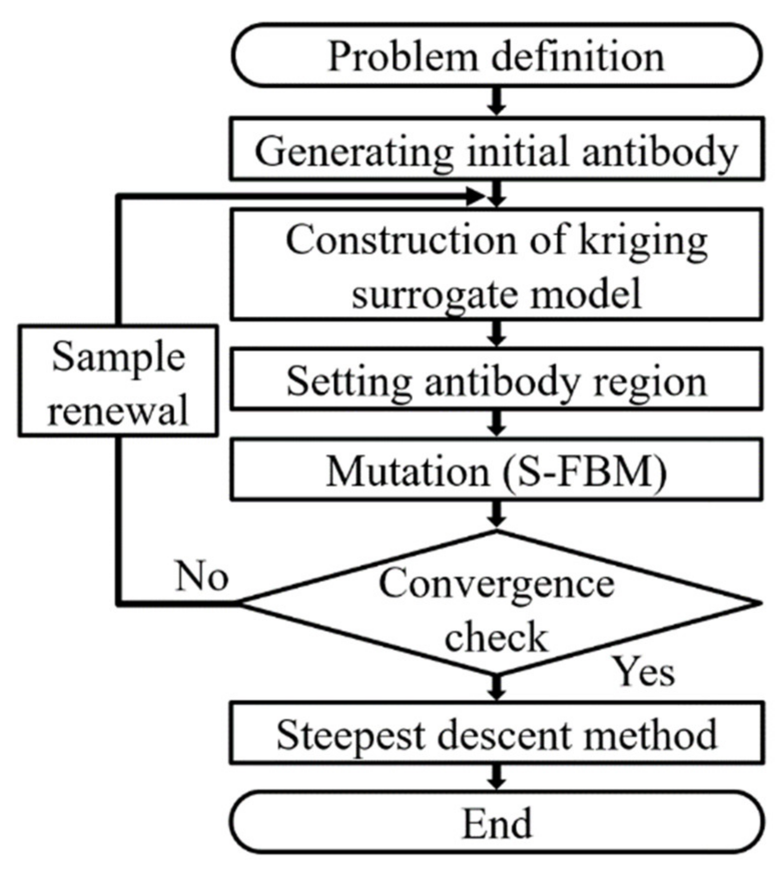
2.4. Flow Chart of the IIA

The flow chart of the IIA is shown in Figure 3. First, the parameters are initialized, and the constraints, such as range of parameters, are set. Initial antibodies are generated by the Latin hypercube sampling method, which provides an efficient way of sampling from entire distributions [14,15]. The surrogate model is constructed with existing samples and provisional solutions are derived. Using the contour function of the MATLAB, the antibody region can be specified. Continually, mutation is generated with S-FEM at the point farthest from the existing samples. This process is repeated until the provisional solution does not change. If the convergence condition is satisfied, provisional solutions are differentiated into memory cells. Finally, each memory cell converges to actual solutions using the SDM, and the algorithm is terminated.

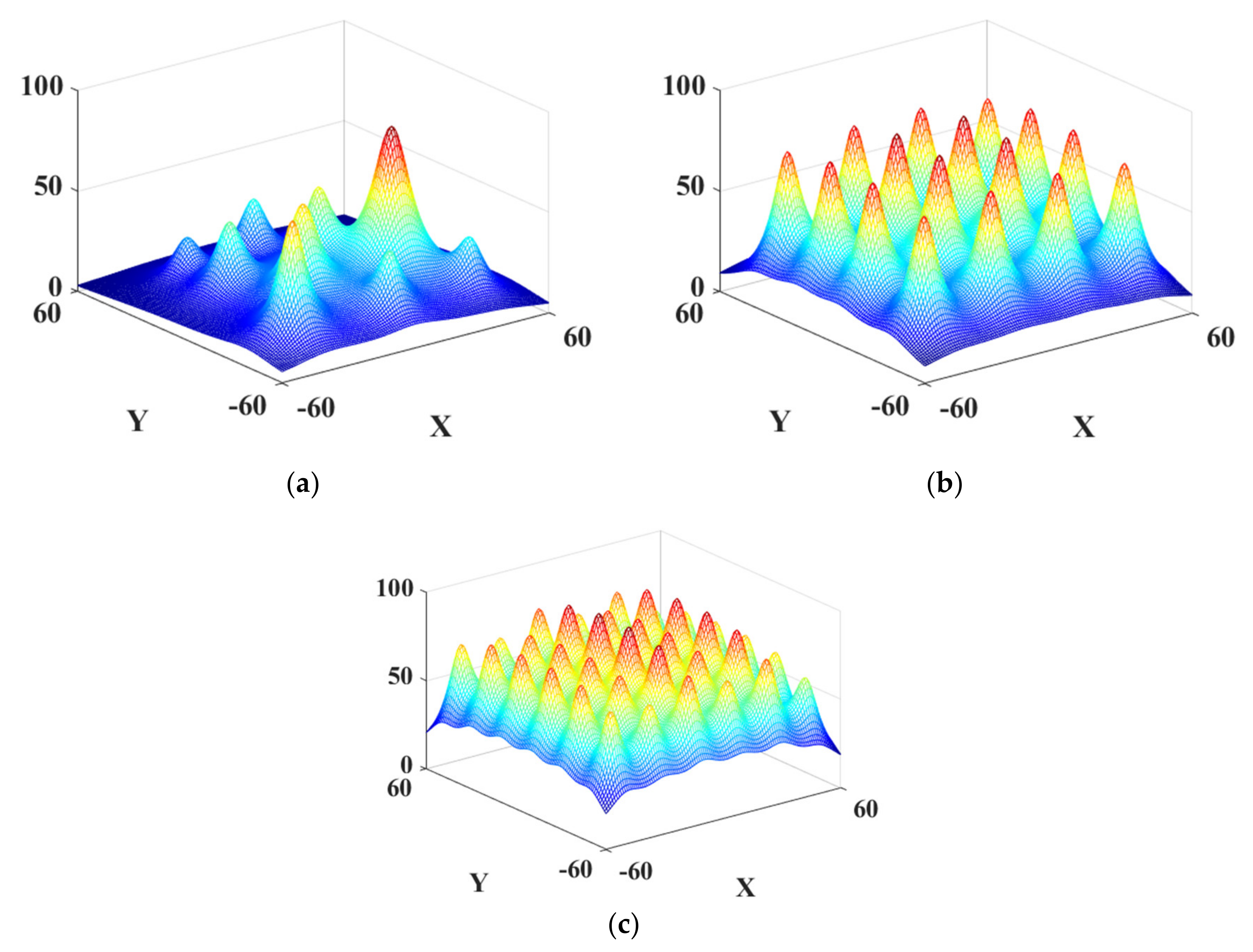
3. Performance Verification

The conventional IA and the proposed IIA are applied to the optimization of mathematical test functions with many local solutions to verify the performance. Each test function is shown in Figure 4, and they are defined as:
f x , y = i = 1 n p b i 1 + x x i 2 + y y i 2 / a i
where np is the number of solutions, (xi, yi) is the position of the actual solution, ai and bi determine the values of the solutions, and np of the test functions 1, 2 and 3 are 11, 16 and 36, respectively. The index indicating the performance is set as the number of function calls required to converge and the convergence rate, which is the average of each value of found solutions divided by the value of the corresponding actual solutions. The test was conducted 100 times, and the average of each test result is tabulated in Table 1. As mentioned earlier, the conventional IA requires an excessive number of function calls to converge to an accurate solution. On the other hand, the proposed algorithm can converge to more accurate solution with about 90%, 95%, and 93% fewer function calls at test functions 1 to 3 than IA. Such function call reduction effect is maximized when the optimization algorithms are applied to FEA. For example, supposing that FEA, which takes 100 s for one function call, is applied to test function 2, total computation time for the IA and IIA is about 212.78 h and 10.22 h, respectively. Therefore, the proposed algorithm can drastically reduce the computation time for optimization using FEA.

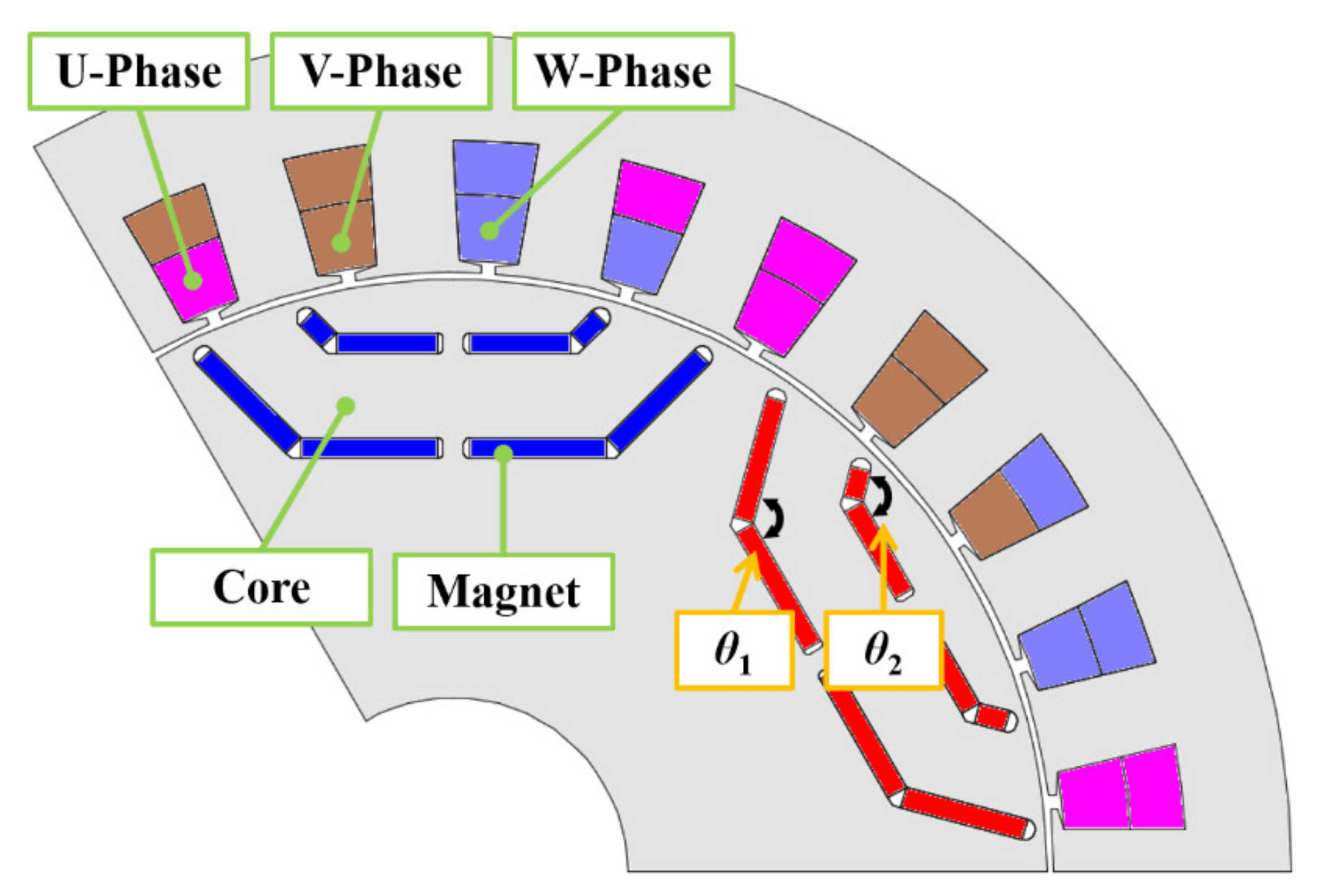
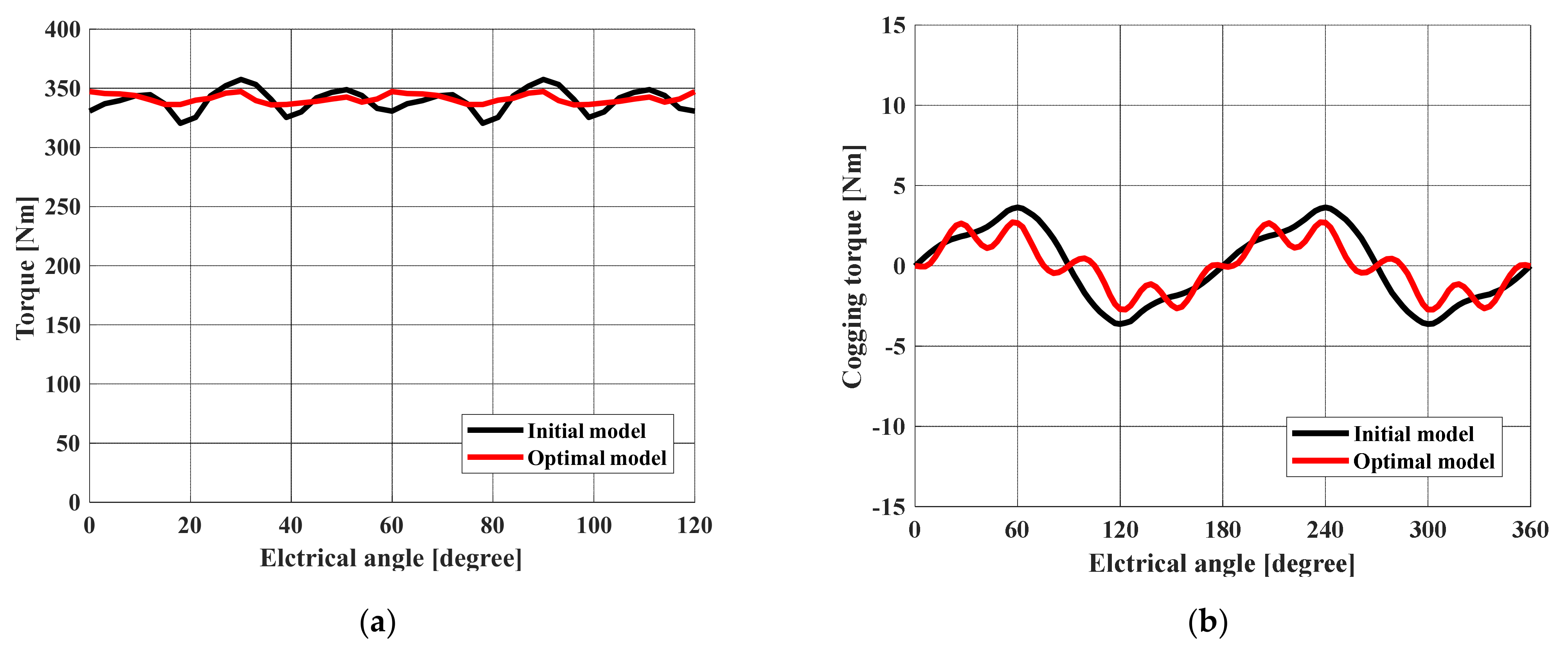
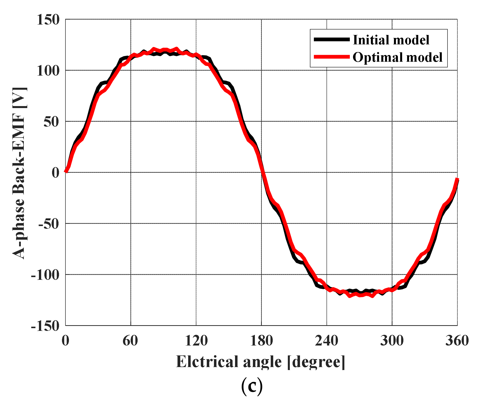
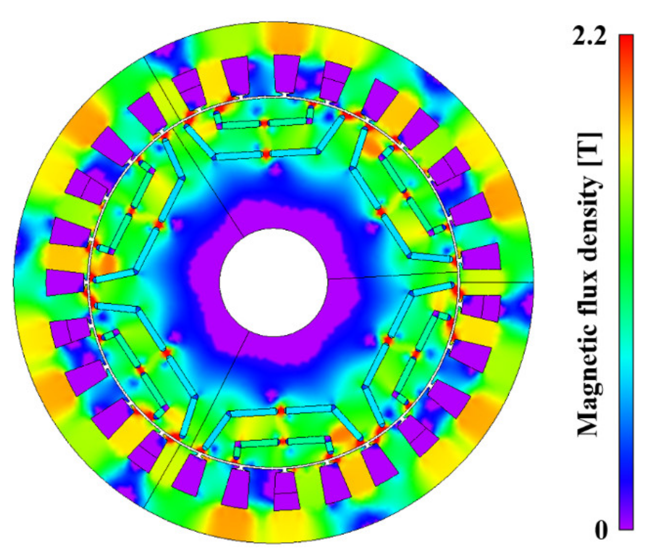
4. Optimal Design of an IPMSM for a FCEV Traction Motor

The optimal design of an IPMSM for a FCEV traction motor using the IIA was executed to verify the applicability of the design of practical electric machines. JMAG, which is a commercial FEA tool, was used for the accurate analysis of the IPMSM.
To apply the design variables on the JMAG, two Matlab codes are required: IIA code and JMAG execution code. The overall optimization process is conducted using the IIA code, and JMAG execution code is composed with JMAG program instructions. On the JMAG execution code, the points consisting of the motor (for example, the coordinates of vertex points indicating the position of the magnet) are parameterized. When the new sample with design variables (v1, v2) is added during the IIA code and requires function call, the values are sent to JMAG execution code. In the JMAG execution code, the new structure is built using the design variables (v1, v2). Then the electromagnetic analysis of new structure is conducted by the JMAG, and the FEA result can be obtained. Finally, the result is transferred to the IIA code as objective function value as (v1, v2, result), and the optimization procedure is progressed. In other words, whenever the sample is added during the algorithm process, the topology in which the corresponding variables are applied is created, and the torque ripple, that is obtained through the on-load analysis, becomes as the objective function value. The design requirements and specifications are listed in Table 2 and Table 3, and are determined according to [1], which targets the same design subject.
For the traction motors for FCEV, low torque ripple is required as the torque ripple causes noise and vibration of the vehicle, resulting in poor driving comfort and poor control stability [1,11]. Therefore, the objective function was determined to minimize the torque ripple. When the target of the design optimization changes, other appropriate design variables could be selected. For example, if one designates the appropriate design parameters when the objective is efficiency improvement, and proceeds with the optimal design using IIA, an optimal design with improved efficiency can be obtained. Additionally, when designing the IPMSM, other performance metrics, such as the average torque or cogging torque, should be considered. Accordingly, both global solution and local solutions should be searched. The IIA is noteworthy, as it obtains all the global and local solutions of the one objective, and the designer or engineer can select optimal solutions comparing other performances. The configuration of the 1/3 periodic analysis model is shown in Figure 5, and design variables are selected as the angle of each magnet layers, because the magnet placement inside the rotor affects the torque ripple [11]. The ranges of θ1 and θ2 were 110°–160° and 100°–160°, respectively.
The total number of function calls to converge was 789, and it takes about 5000 min. As a result of design optimization, the surrogate model of the torque ripple according to the design variables was obtained and is shown in Figure 6. It is obvious that the objective region is nonlinear and has complex shape with many local solutions. Among obtained global and local solutions, some solutions that are located too closely are eliminated considering the manufacturing tolerance, and three candidates are selected.
Optimized design variables and current phase angles of each model are listed in Table 4. Whenever new samples are added during the optimization, current phase angle finding step is applied, because the current phase angle of maximum average torque varies according to the shape of the motor [11].
The load and no-load FEA results of obtained models are shown in Table 5. In terms of torque ripple, candidate 3 is a global solution. However, when designing the traction motor for FCEV, various performances, such as average torque and cogging torque, should be considered. For the average torque, candidate 3 showed the highest value. Regarding the no-load results, the cogging torque, total harmonic distortion (THD) of three-phase back electromotive force (B-EMF), and amplitude of B-EMF is compared. Candidate 1 is the best for the cogging torque, and candidate 3 shows superior performance for THD and amplitude of B-EMF. Candidate 3 is selected for an optimal model through comparison in various aspects of the motor.
The torque waveform of initial model and optimal model is shown in Figure 7a. The torque ripple of the optimal model is decreased by 69.0% compared to the initial model. Cogging torque waveform is shown in Figure 7b, and the cogging torque of optimal model is 25.6% relieved. A-phase B-EMF waveform is shown in Figure 7c. The THD and amplitude of B-EMF are improved by 34.1% and 2.1%, respectively, relative to the initial model. The power characteristics of both models are listed in Table 6, and magnetic flux density distribution plot is shown in Figure 8.
The traction motors for FCEV operate in various speed ranges. The maximum mechanical stress acts on the center-post and bridge of the rotor, and such parts are vulnerable for breakage at high-speed operating point. To verify the structural rigidity of the optimal model, analysis on mechanical stress is conducted. The parameters for the mechanical stress analysis are listed in Table 7. The results of mechanical analysis at rated speed and maximum speed are shown in Figure 9. For both cases, maximum stress is applied to center-post and Von Mises stress value are 20.50 MPa and 227.76 MPa, respectively. The yield stress of the rotor core is 250 MPa, and it can be concluded that the optimal model is endurable for breakage at the maximum speed.

5. Conclusions

This paper proposes an optimization algorithm for electric machine design. By using the interpolation method, the IIA minimizes the unnecessary function calls and drastically reduces the computational burden. The superior performance of the proposed algorithm was verified by applying the IA and IIA to three mathematical test functions and comparing each convergence rate and the number of function calls to converge. Finally, the IIA could successfully derive the optimal design of an IPMSM when the objective is torque ripple, and the feasibility of applying the IIA to practical electric machine design was proven.

Author Contributions

Investigation, J.-C.S.; writing—original draft preparation, J.-C.S.; writing—review and editing, M.-K.B., S.-H.P. and D.-K.L. All authors have read and agreed to the published version of the manuscript.

Funding

This research received no external funding.

Acknowledgments

This research was supported by Korea Electrotechnology Research Institute (KERI) Primary research program through the National Research Council of Science & Technology (NST) funded by the Ministry of Science and ICT (MSIT) (No. 21A01082).

Conflicts of Interest

The authors declare no conflict of interest.

References

  1. Lim, D.-K.; Yi, K.-P.; Jung, S.-Y.; Jung, H.-K.; Ro, J.-S. Optimal Design of an Interior Permanent Magnet Synchronous Motor by Using a New Surrogate-Assisted Multi-Objective Optimization. IEEE Trans. Magn. 2015, 51, 8207504. [Google Scholar] [CrossRef]
  2. Zhang, Y.; Xu, D.; Liu, J.; Gao, S.; Xu, W. Performance Improvement of Model-Predictive Current Control of Permanent Magnet Synchronous Motor Drives. IEEE Trans. Ind. Appl. 2017, 53, 3683–3695. [Google Scholar] [CrossRef]
  3. Seo, J.-H.; Woo, D.-K.; Chung, T.-K.; Jung, H.-K. A Study on Loss Characteristics of IPMSM for FCEV Considering the Rotating Field. IEEE Trans. Magn. 2010, 46, 3213–3216. [Google Scholar] [CrossRef]
  4. Wu, C.; Yang, J.; Li, Q. GPIO-Based Nonlinear Predictive Control for Flux-Weakening Current Control of the IPMSM Servo System. Energies 2020, 13, 1716. [Google Scholar] [CrossRef] [Green Version]
  5. Wu, J.; Wang, J.; Gan, C.; Sun, Q.; Kong, W. Efficiency Optimization of PMSM Drives Using Field-Circuit Coupled FEM for EV/HEV Applications. IEEE Access 2018, 6, 15192–15201. [Google Scholar] [CrossRef]
  6. Ren, W.; Xu, Q.; Li, Q.; Zhou, L. Reduction of Cogging Torque and Torque Ripple in Interior PM Machines with Asymmetrical V-Type Rotor Design. IEEE Trans. Magn. 2016, 52, 8104105. [Google Scholar] [CrossRef]
  7. Kim, H.-S.; Kwon, B.-I. Optimal design of motor shape and magnetization direction to obtain vibration reduction and average torque improvement in IPM BLDC motor. IET Electr. Power Appl. 2017, 11, 378–385. [Google Scholar] [CrossRef]
  8. Kim, W.-H.; Kim, K.-S.; Kim, S.-J.; Kang, D.-W.; Go, S.-C.; Chun, Y.-D.; Lee, J. Optimal PM Design of PMA-SynRM for Wide Constant-Power Operation and Torque Ripple Reduction. IEEE Trans. Magn. 2009, 45, 4660–4663. [Google Scholar] [CrossRef]
  9. Hao, J.; Suo, S.; Yang, Y.; Wang, Y.; Wang, W.; Chen, X. Optimization of Torque Ripples in an Interior Permanent Magnet Synchronous Motor Based on the Orthogonal Experimental Method and MIGA and RBF Neural Networks. IEEE Access 2020, 8, 27202–27209. [Google Scholar] [CrossRef]
  10. Fang, L.; Kim, S.-I.; Kwon, S.-O.; Hong, J.-P. Novel Double-Barrier Rotor Designs in Interior-PM Motor for Reducing Torque Pulsation. IEEE Trans. Magn. 2010, 46, 2183–2186. [Google Scholar] [CrossRef]
  11. Son, J.-C.; Kang, Y.-R.; Lim, D.-K. Optimal Design of IPMSM for FCEV Using Novel Immune Algorithm Combined with Steepest Descent Method. Energies 2020, 13, 3395. [Google Scholar] [CrossRef]
  12. Lim, D.-K.; Woo, D.-K.; Yeo, H.-K.; Jung, S.-Y.; Ro, J.-S.; Jung, H.-K. A Novel Surrogate-Assisted Multi-Objective Optimization Algorithm for an Electromagnetic Machine Design. IEEE Trans. Magn. 2015, 51, 8200804. [Google Scholar] [CrossRef]
  13. The Mathworks Inc. Contour. Available online: http://www.mathworks.com/help/techdoc/ref/contour.html (accessed on 29 June 2021).
  14. Yu, H.; Chung, C.Y.; Wong, K.P.; Lee, H.W.J.; Zhang, J.H. Probabilistic Load Flow Evaluation with Hybrid Latin Hypercube Sampling and Cholesky Decomposition. IEEE Trans. Power Syst. 2009, 24, 661–667. [Google Scholar] [CrossRef]
  15. Kang, Y.-R.; Son, J.-C.; Lim, D.-K. Optimal Design of IPMSM for Fuel Cell Electric Vehicles Using Autotuning Elliptical Niching Genetic Algorithm. IEEE Access 2020, 8, 117405–117412. [Google Scholar] [CrossRef]
Figure 1. Conceptual schematic of MCS and S-FBM.
Energies 14 03904 g001
Figure 2. Principle of the SDM.
Energies 14 03904 g002
Figure 3. Flow chart of the IIA.
Energies 14 03904 g003
Figure 4. Mathematical multi-modal test function. (a) Test function 1 with 11 peaks; (b) Test function 2 with 16 peaks; (c) Test function 3 with 36 peaks.
Energies 14 03904 g004
Figure 5. Configuration of the IPMSM and design variables.
Energies 14 03904 g005
Figure 6. Surrogate model of torque ripple domain according to the magnet angle of IPMSM. (a) Contour plot; (b) Three-dimension plot.
Energies 14 03904 g006
Figure 7. Characteristic comparison of initial model and optimal model. (a) Torque waveform; (b) Cogging torque waveform; (c) A-phase B-EMF waveform.
Energies 14 03904 g007aEnergies 14 03904 g007b
Figure 8. Magnetic flux density of optimal model.
Energies 14 03904 g008
Figure 9. Von Mises stress plot of the optimal model. (a) At rated speed; (b) At maximum speed.
Energies 14 03904 g009
Table 1. Test result of the IA and IIA.
Test function 1
(11 peaks)
Number of function calls (EA)Convergence rate
(%)
IA275096.99
IIA27699.04
Test function 2
(16 peaks)
Number of function calls (EA)Convergence rate
(%)
IA766097.64
IIA36899.71
Test function 3
(36 peaks]
Number of function calls (EA)Convergence rate
(%)
IA10,95098.97
IIA73899.89
Table 2. Requirements of an objective motor.
RequirementValue
Rated torque330 (Nm)
Rated output103.7 (kW)
Rated/maximum speed3000/10,000 (rpm)
Torque rippleLess than 10 (%)
Table 3. Specifications of an objective motor.
ParameterValue
Pole/slot number6/27
Stator inner/outer diameter (mm)172/240
Rotor inner/outer diameter (mm)50/170
Air gap (mm)1
Bridge, Center-post (mm)1.5
Stacking length (mm)230
Stator and rotor core materialPOSCO 35PN230
Permanent magnet materialNEOMAX-42
(Br = 1.30 [T])
Permanent magnet thickness (mm)3
Current density (Arms/mm2)13.5
Table 4. Design variables of the initial model and three candidates.
ModelInitial ModelCandidate 1Candidate 2Candidate 3
θ1
(degree)
110.0118.9137.0129.0
θ2
(degree)
158.8138.7115.6110.8
AC phase
(degree)
40424242
Table 5. Performance comparison of each model.
ModelInitial ModelCandidate 1Candidate 2Candidate 3
Torque ripple
(%)
10.926.574.033.38
Average torque
(Nm)
339.52340.65336.93341.22
Cogging torque
(Nm)
7.154.454.475.32
THD (BEMF)
(%)
11.6711.538.797.69
BEMF
(Vpk)
118.76115.97116.20121.20
Table 6. Power characteristics of the initial model and the optimal model.
ModelInitial ModelOptimal Model
Copper loss2212.16 (W)2212.16 (W)
Iron loss686.11 (W)679.83 (W)
Total loss2898.27 (W)2891.99 (W)
Input power109.61 (kW)110.06 (kW)
Output power106.71 (kW)107.16 (kW)
Efficiency97.36 (%)97.37 (%)
Table 7. Parameters for the mechanical stress analysis.
RequirementValue
Young’s modulus (Core/Magnet)210/160 (GPa)
Poisson’s ratio (Core/Magnet)0.3/0.24
Density (Core/Magnet)7850/7500 (kg/m3)
Rotation speed3000/10,000 (r/m)
Yield stress250 (MPa)
Publisher’s Note: MDPI stays neutral with regard to jurisdictional claims in published maps and institutional affiliations.

