1. Introduction
Wind energy production is one of the most promising alternatives to meet the growth in energy demand in compliance with the growing commitments to clean energy. In particular, offshore wind farms stand out as a plausible solution to increase energy production with a zero carbon footprint, taking advantage of the fact that turbines at sea allow better use of the wind, which is stronger and more stable than on land. [
1]. Moreover, offshore turbines overcome some of the drawbacks of onshore wind turbines, such as visual and acoustic impact, which still remain partially unsolved.
In traditional offshore wind structures, the turbine is attached to the seabed by different bottom-fixed foundations. They require shallow water for their installation, up to 50–60 m [
2]. This, together with the requirement that they be located at a certain distance from the coast, has made it impossible for some countries to exploit this marine technology. This fact, together with the impact they can have on the seabed [
3], has made the installation of bottom-fixed offshore wind turbines (BOWT) close to reaching a plateau due to water depth limitations.
Floating offshore wind turbines (FOWT) can be deployed at depths between 60 and 900 m, which makes it possible to overcome the drop-off that exists in many countries a few meters from the coast. The most general types of floating turbines are based on three floating mechanisms, namely, buoyancy, ballast, and mooring. They correspond to the barge type turbines, the spar buoy, and the tension leg platform, respectively. The subject of floating foundations is not easy and the cost of the wind turbine is highly dependent on it. For this reason, new proposals are being designed to achieve a robust support for the wind turbine [
4]. This is important since the hydrodynamic forces that reflect the direct influence of the waves mainly affect the foundation, as has been verified in several design prototypes created by certain companies [
5], such as the BW Ideol, Atlantis, or SeatWind.
This work focuses on barge-type floating wind turbines. These floating structures achieve stability through the use of distributed buoyancy, taking advantage of a weighted water plane area at the righting moment. The mooring lines allow us to maintain position.
Barge platforms, although quite massive and anchored to the seabed, can withstand great movements. Therefore, the installation of a wind turbine mounted on a floating platform will undoubtedly increase the loads on the structure and alter the operating conditions for energy production, which will require an analysis to ensure its viability in both terms.
Following the so-called KISS principle, preliminary load analyses on floating wind turbines have been carried out, considering the installation of an onshore wind turbine on a floating platform [
6]. This analysis proves that waves and wind amplify motions and loads on the structure due to an inverted pendulum effect. For example, in a recent article by Ikoma et al. [
7], the influence of turbine rotations on the movement responses of the floating system are studied. The authors suggest that the influence of water movements on pitch angle should be addressed, particularly for head-sea conditions. With hydrodynamic forces, the sea-land relationships of the internal shear force and bending moments increase from the tip of the blade, through the drive train and nacelle, to the base of the tower. Compared to onshore designs, the sea-to-land ratio of damage equivalent loads (DEL) to bending moment of the longitudinal tower base of the floating barge systems is seven times higher, which will certainly affect its certification, maintenance, and security [
8]. This problem shows the need to modify the design of conventional onshore wind turbines, which has attracted the attention of the scientific community.
A wide variety of initiatives have been proposed to reduce the loads of barge FOWTs, some of them based on a modification of the blade pitch or generator control laws [
9], while others make use of structural control devices [
10]. Both approaches allow to some extent the reduction of vibrations. In all cases, a dynamic model is needed to simulate the system behavior, both to optimize the control law and to demonstrate the achieved performance.
The FOWT models under study are commonly considered a reference system, that is, they correctly represent the physical properties of the wind system. This is because there is no experimental data available from the actual turbine. However, there are solutions in the form of high-fidelity models built using simulation software, which allow us to obtain synthetic experimental data. For instance, there is a high-fidelity simulation software package that reproduces the behavior of FOWTs with high precision, called fatigue, aerodynamics, structures, and turbulence (FAST). However, one of the biggest drawbacks of this software is its computational cost if it is used in an iterative loop, in an optimization process, or integrated into a model-based control loop for real-time operation. Therefore, a possible solution is to develop reduced dynamic models. Basically, they are based on simple dynamic equations that must be adjusted by an identification algorithm based on the response of the reference system.
For this reason, this study presents a general methodology for the identification of reduced dynamic models of floating offshore wind turbines. It is a mathematical control-oriented model of a barge FOWT. The simplified model is developed based on the Euler–Lagrange equations, as in [
11]. The model is then linearized considering operating conditions around small platform pitch angles, but without neglecting the most relevant physical phenomena of the dynamics of the wind turbine and the platform. The parameters of the model are identified through simulations, and finally the model is validated. FAST software has been used in all phases of the development of this model.
The proposed modeling approach has two advantages. On the one hand, the mathematical model obtained is manageable and new elements can be incorporated, maintaining the physical interpretability of the variables involved. In fact, in this work an additional DoF is added, a passive control device, as an example. Similarly, it would be possible to include other active/passive control devices in different parts of the FOWT to analyze their effect on the dynamics of the floating system. On the other hand, a significant contribution of this control-oriented model is the fact that the identification has been validated with the control device integrated into the system. This has been possible due to the reduced order of the model and provides more accurate results than other modeling approaches with which it has been compared.
The identification methodology presented here has been successfully used in the investigation of control devices that have been applied to reduce structural loads in a barge FOWT turbine [
12,
13,
14,
15].
The structure of the paper is as follows.
Section 2 summarizes some recent work on floating offshore wind turbine modeling and identification.
Section 3 describes the identification methodology. To obtain the model parameters, the generation of synthetic data is required, which is explained in
Section 4.
Section 5 shows the mathematical model obtained.
Section 6 presents the identified parameters and the validation of the model. Conclusions and future lines of research end the paper.
2. Related Works
Systems identification methods have been widely applied in different fields. In particular, in the area of floating offshore wind turbines, some authors have begun to use this methodology to determine models that would allow the development of a broader range of control strategies, which would lead to improving system performance and reducing loads and thus fatigue of the wind turbines [
12].
In [
15], the authors present a model-based blade pitch controller for a spar-type FOWT scale prototype. They obtain the model from experimental input-output measurements using systems identification methods. The mathematical model obtained in this case is a linear state space model. Authors in [
16] apply systems identification techniques on existing experimental data in order to build a mathematical model for a FOWT platform and, in this way, investigate the behavior of the structure. A 1:35 scale prototype of the NREL 5 MW TLG offshore wind turbine is used. The base of this turbine is mathematically modeled, showing its displacement due to a series of irregular waves. Specifically, it focuses on surge motion.
The suitability of installing a TMD in the nacelle of a barge-type FOWT to reduce vibrations is studied in [
14]. The system dynamics are derived using the Lagrange’s equations approach. The wind turbine parameters are identified using the nonlinear least squares Levenberg–Marquardt (LM) algorithm. In [
17], identification methods are used to obtain the Morison drag coefficients and the case of irregular waves is studied. The reduced-order model used has five degrees of freedom and it is formulated both in the time-domain and in the frequency-domain.
In addition to these, and still within the wind turbine technology, the work presented in [
18] considers the problem of calibration and validation of a reduced order wind farm model; the authors used the flow redirection and induction in steady-state approach to design a model-based wind farm control with the use of experimental measurements. Model parameters are identified from observations made on a scale prototype in a wind tunnel. It has been subjected to different load profiles that consider the misalignment of the wind and waves. These results are generalized and experimentally validated in a wind farm formed by three scale wind turbines that interact with each other.
Similarly, in [
19], the authors discuss several model calibration studies in order to evaluate the tuning of the model parameters. The final aim is to improve the matching between the numerical simulations and the experimental test data. It was applied to the model of the 1:50-scale DeepCwind semisubmersible system that was tested at the Maritime Research Institute Netherlands ocean basin.
In the paper by [
20], the identification of a grey-box mechanical model of a large scale wind turbine is carried out. Authors test different strategies and evaluate them from the control point of view.
On the other hand, the standard design procedures and some of the modeling and simulation tools for offshore structures come from existing technology and the experience of the offshore oil and gas extraction industry. Some of the programs used focus only on a particular part of the turbine, such as SeaFEM for the hydrodynamic part [
21], or DNV GL for the blades and for the mooring system [
22]. Most are based on numerical simulation and require great computational power (OrcaFlex and COUPLE) [
23]. Some of them work in the time domain, such as HAWC2 (2nd generation horizontal axis wind turbine simulation code) or the well-known NREL FAST, which can be seen as a software library with different modules for simulation of horizontal axis wind turbines, including floating ones. It allows us to interact with different dynamic analysis software packages such as Matlab. Given that floating turbines are in the early stage of development, it must be kept in mind that the data to validate the computational models is very limited.
In the work presented in [
24], experiments with regular and irregular waves, and with different wind conditions, were carried out in order to realistically model a TLP wind turbine. The model developed was validated with the one provided by FAST, with satisfactory results in most tests. However, under certain conditions the numerical model could not accurately predict the response of the platform. From another point of view, [
25] propose a holistic model of a FOWT that includes the most relevant physical effects of the system dynamics. It consists, at its core, of a flexible multibody system. A non-linear model is first obtained, which was then linearized to simplify it. Both models were compared with a more accurate and higher-fidelity model. It has been proven that with both models, the response of the system without external loads and the response considering the loads due to wind and waves can be well obtained.
Zhou et al. [
26] present numerical modelling of a FOWT developed using the numerical simulation tool computational fluid dynamics (CFD). It allows for the study of the dynamic response of the wind turbines under extreme waves. In [
27], a FOWT is analyzed in detail using CFD with an emphasis on the hydrodynamic damping.
Most of these modelling and identification approaches, as in our case, are oriented to the design of control strategies for the wind turbine or to the structural control of the floating device [
28,
29].
3. Identification Methodology
The proposed methodology aims to develop a simplified control-oriented model of floating wind turbines. Due to the lack of real data, given that experimentation with these new floating devices is still under development, new approaches are necessary to identify and validate computational models.
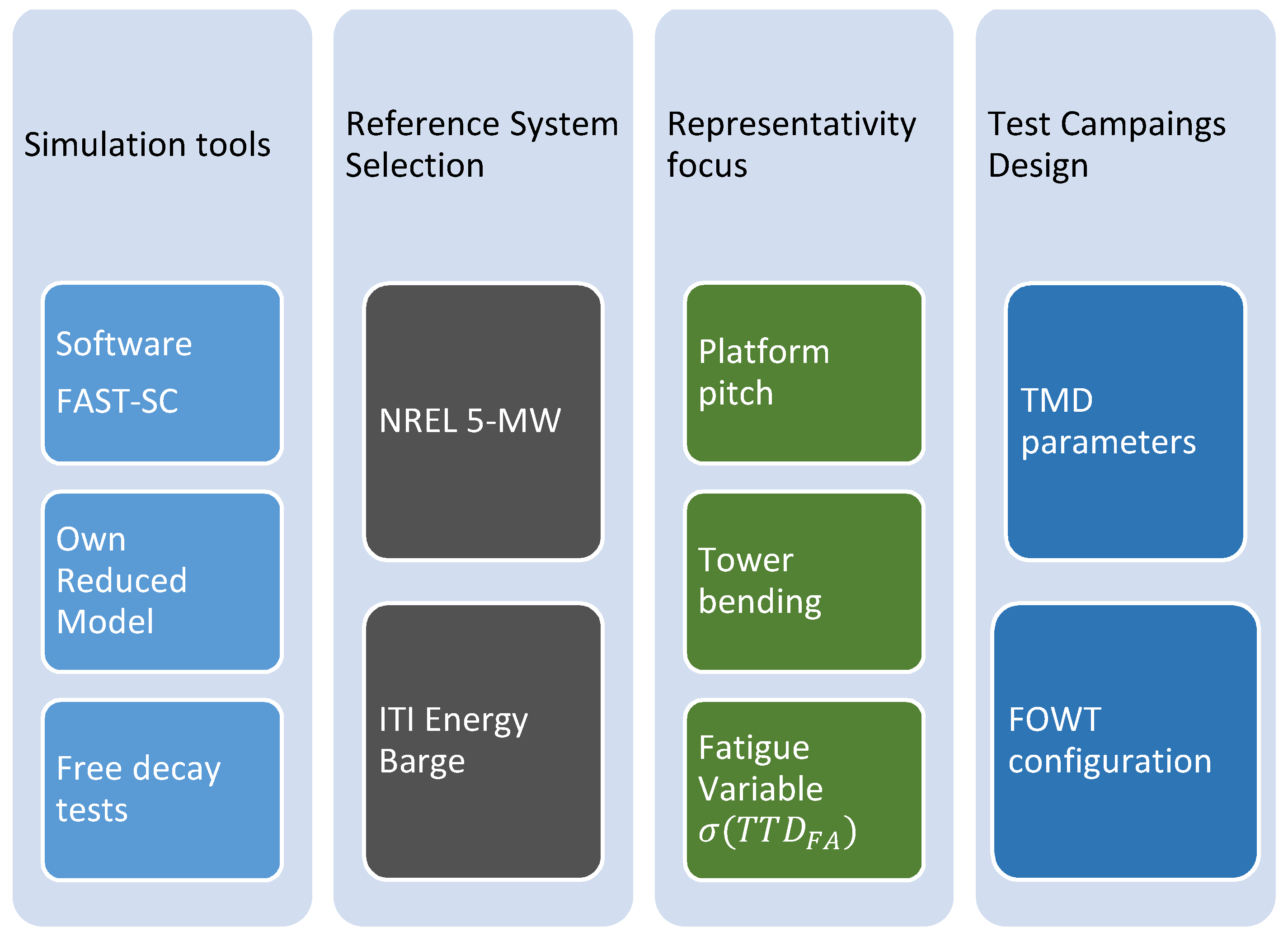
Figure 1 shows the key points of the identification methodology that will be described in the following subsections. These can be summarized as:
Simulation tools, using both the standard software, FAST-SC [
30], and using our own model of the FOWT implemented with Matlab/Simulink. The floating turbine is simulated under free decay conditions. The FAST model will be used to get synthetic data that will allow us to identify and validate the proposed reduced model.
Reference system, defined by the technical characteristics of a particular type of turbine (NREL 5 MW) and the specific barge used (ITI Energy).
Representative approach, which is determined by the variables of interest. In our case, the platform pitch and the bending of the tower have been selected. In addition, the variable chosen to measure structural fatigue is the standard deviation of the Tower Top Displacement in the Fore-Aft direction, σ.
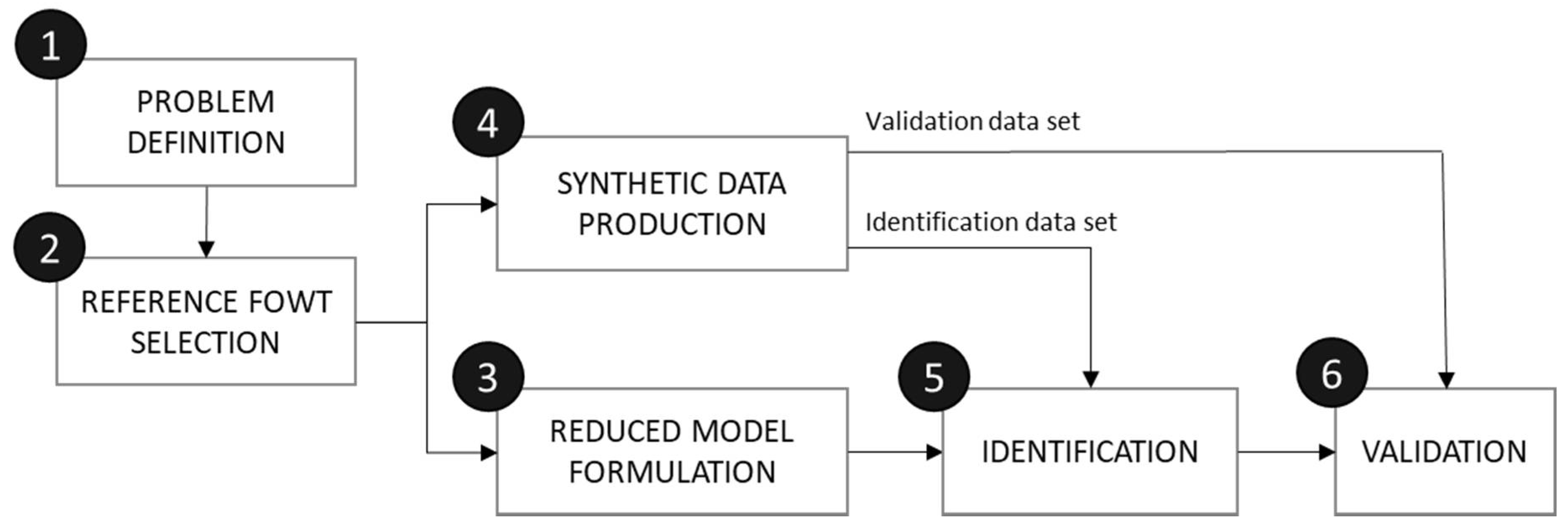
The development of the reduced dynamic model will follow the next six phases, shown in
Figure 2:
Problem definition
Reference FOWT selection.
Synthetic data production.
Reduced dynamic model equations formulation.
Reduced dynamic model identification.
Reduced dynamic model validation.
The precision of the model depends on the test conditions under which the synthetic data is obtained; that is, of the identification and validation data sets. To obtain the best starting parameters, we introduce the concept of “test data diversification”. This essentially consists of varying the settings to generate different test data, which will feed into the identification and validation processes. This ensures that the final model includes the desired modeled dynamics without overfitting the test data sets. In practice, this solution provides satisfactory identification accuracy and robust validation results under different operating conditions. Diversification should be applied to variables that can be adjusted to produce a data set. For multivariable configurations, this process can be done in series or in parallel. This study explains an example of serial test data diversification, where several rounds of identification and validation are first performed to select the optimal identification algorithm. The process is then repeated, varying the duration of the test, and finally it is repeated again to decide the initial conditions to be used. Parallel test data diversification should vary each configuration at a time to select the best one.
4. Synthetic Data Generation
The scope of this study is determined by the intended use of the FOWT model. The main objective that arises with the modeling and control of these floating devices is to reduce the fatigue that can appear due to the vibrations in the structure, while producing the maximum energy. In [
30], it was determined that the fatigue in the structure is mainly due to the first collective platform pitch-tower bending mode, which especially affects the base of the tower. Therefore, this is the variable chosen in this work to be analyzed, which is related to the platform pitch and the bending moment of the base of the tower.
Besides, the floating system includes a passive structural control device to reduce the FOWT structural loads. Particularly, a tuned mass damper (TMD) is installed in the nacelle in order to damp out the fore-aft tower displacement. In order to tune the TMD parameters, an optimization loop that includes the dynamic model is necessary.
4.1. Baseline FOWT
In this paper, we work with the National Renewable Energy Laboratory (NREL) 5-MW wind turbine [
30], as in many other research projects supported by the U.S, the European Union, and the International Energy Agency. It is quite a large horizontal-axis, three-bladed, upwind, variable speed, pitch-controlled turbine, with a 126 m rotor diameter and 90 m hub height. Some of its main characteristics are presented in
Table 1.
The 5-MW wind turbine is mounted on a platform designed by the Department of Naval Architecture and Marine Engineering at the Universities of Glasgow and Strathclyde with the company ITI Energy [
31]. The platform is square in shape and is attached to the seabed by eight mooring lines to prevent it from drifting. The main platform characteristics are presented in
Table 2.
4.2. Synthetic Experimental Data Generation
The FOWT described above is considered the baseline turbine, thus it is necessary to simulate it and the variables that are going to be modelled with as much accuracy as possible. To that end, a high-fidelity simulation software must be chosen. There are several software solutions for simulating multibody system dynamics, including proprietary and open-source alternatives.
In this work, the NREL aeroelastic computer-aided engineering tool FAST is used to generate the synthetic experimental data that will feed the identification and validation processes. Specifically, an advance version called FAST-SC [
32], which includes the possibility of adding structural control capabilities, has been used. This extended tool is not only precise, but also fully compatible with the reference FOWT. The versatility of FAST allows the user to fully set up the simulation, including the initial conditions, the disturbances, and the active degrees of freedom.
The model has been designed to perform free decay tests, so these kinds of simulation experiments are selected. They consist of the observation of the system response from an initial condition, which is out of the system rest position. In this case, in order to implement free decay tests, all conditions were initialized to zero except the platform pitch angle (PtfmPitch). The tests were diversified into a series of processes through three phases: (i) algorithm selection, (ii) test duration determination, and (iii) initial conditions specification. According to the literature, the most used configuration is: 100 s duration and 5-degree initial platform pitch. It was decided to diversify the tests around those values. The following data sets were generated:
Identification data sets: these consists of free decay tests of the FOWT with the TMD device deactivated. First, as is common in experiments with FOWT, free decay tests were carried out in order to obtain data for the identification. Thus, all DOF were switched off except for the first fore-aft tower bending mode (TwFADOF1) and the platform pitch rotation (PtfmPDOF). A total of twenty-five identification data sets were generated combining {3, 5, 8, 10} degrees initial platform pitch and {50, 80, 90, 100, 150, 200} seconds duration. In the final phase, an additional data set was added with 2 degrees initial platform pitch and 100 s duration.
Validation data sets: these were obtained considering an extra degree of freedom, the TMD (TmdXDOF), which helped to modify the dynamics of the system and verify the reliability of the model. A total of nine validation tests were applied; first, with {50, 80, 90, 100, 150, 200} seconds duration and 5 degrees initial platform pitch. Later, three more tests were carried out with 100 s duration and {3, 8, 10} degrees initial platform angle. This is not a homogeneous parametric search, in fact, the required data sets were determined according to the results obtained after the identification tests. For the validation, the TMD was tuned with the parameters proposed by Lackner and Rotea [
32], that is, mass is 20,000 Kg, the spring stiffness is set to 5000 N/M, and damping coefficient is 9000 Ns/m.
5. Reduced Dynamic Model of the FOWT
In this section, we show how a simplified model of the FOWT is obtained. It represents the dynamics of the wind turbine.
Figure 3 shows the FOWT system with a fore-aft TMD in the nacelle, and the main variables.
The main assumptions made in order to obtain the reduced dynamic model are the following:
The system is considered to be a multibody dynamic system with a reference point P at the tower base, in accordance with Jonkman [
32].
The system has three elements: the barge, the TMD control device, and the wind turbine, the latter made up of the tower and the rotor-nacelle assembly.
The model has three state variables: the translation motion of the TMD, the platform pitch rotation and the tower bending.
The turbine is modelled as an inverted pendulum, with the tower hinged to the platform. The tower fore-aft bending is modeled by a spring and a damper with constant coefficients.
The platform is considered a rigid solid in motion. As seen in
Figure 3, hydrodynamic restoring forces and the effect of mooring lines can be represented by the stiffness of a pier, and hydrodynamic damping forces and other effects of waves by a shock absorber. The coefficients of these elements are assumed to be constant.
The aerodynamic and hydrodynamic forces due to the wind and the waves, respectively, have not been included. The wind turbine will be studied under free decay experiments.
The model is obtained as in [
11], using the Euler–Lagrange equation or Lagrange’s equation of the second kind of non-conservative system (1), with
being the n generalized coordinates, i.e.,
i = 1, …, n. The damping forces are the only non-conservative ones in this system.
The Lagrange operator is obtained as the difference between the kinetic energy,
K, and the potential energy,
V.
The kinetic energy,
K, is given by,
The expression of the potential energy is:
where
is the platform pitch,
is the rotation angle of the tower, and
is the TMD linear displacement. The parameters of the TMD are the coefficient
k, associated with the spring stiffness, and d that represents the damping. The
term corresponds to the distance of the center of mass of body
i to the reference point P. Subindex
p refers to the platform and subindex
t to the tower.
Finally, the generalized non-potential forces of the FOWT system are,
Rearranging those equations, the non-linear model of the barge floating wind turbine in the downwind direction is,
It is possible to assume that the platform pitch will never surpass 10°, so the system can be linearized [
11]. The reduced model is then,
6. Dynamic Model Identification
Once the dynamic model equations have been defined and the synthetic experimental data are available, the general model parameters for this particular type of FOWT must be identified. The identification methodology will be applied to obtain the best combination of parameters so as to minimize the difference between the proposed model and the responses of the FAST simulation system.
It should be noted that a non-linear model is being approximated by a reduced linear one, so there will always be some non-modeled dynamic behavior. In addition, all modes of the system must be excited, for which sufficiently large free decay angles must be used, while simultaneously avoiding deviating too much from the system’s expected linear behavior. As it is not possible to determine the ideal operating conditions from synthetic reference data, the use of diversified data sets is key to obtaining good identification.
There are six parameters that have to be identified, namely, spring stiffness, damping coefficient, and inertia moment of the barge platform and of the tower, that is, , , , , , and . The initial assumption of the parameters was crucial to achieving a quick and successful convergence.
Due to the limitations of the computing resources used and time, the maximum number of iterations for the identification processes was limited to three hundred (300). Each identification process can take tens of seconds. The computer used for the tests is an Intel® Core™ i5-8265U Processor, 6 M Cache, up to 3.90 GHz. The operating system is Microsoft Windows 10.
The fitness measurement is the mean squared error (MSE) of the most important variable to be reduced, the tower top displacement in the fore-aft or downwind direction (TTDFA).
As already stated, the tests were diversified in a series of processes composed of three phases: (i) algorithm selection, (ii) test duration selection, and (iii) initial conditions specification. Each of the phases is described with its results and conclusions.
- i.
Algorithm selection.
The optimal identification algorithm for a particular problem may depend on the data sets used and the dynamics to be identified. In this case, twenty identification experiments were performed. Four algorithms were tested: Levenberg–Marquardt least squares search (LM), subspace Gauss–Newton least squares search (GN), adaptive subspace Gauss-Newton search (GNA) and steepest descent least squares search (GRAD). Each of them was used in the identification of the model using the data set with 100 s duration and 5 degrees initial platform pitch. Then, every identification solution was compared with different data sets as presented in
Table 3.
The algorithm selection phase showed that the GRAD algorithm obtained slightly worse results. Finally, the Levenberg–Marquardt least squares search method was selected. This algorithm, also known as the damped least squares method, interpolates between the Gauss–Newton algorithm and the gradient descent method, which means it is a robust method for multivariable identification starting far from the final minimum.
- ii.
Test duration selection.
The second phase was carried out in a similar manner to the previous one. Six different identification solutions were obtained, using a 5 degree initial platform pitch data set with different simulation times. Then, the solutions were compared with the data sets.
Results can be found in
Table 4, where the three best results (lowest error) are in bold for each column. It is clear that the identification that lasts 100 s data set gives the more consistent results.
- iii.
Initial platform pitch selection.
This last step aims at selecting an optimal initial condition for the platform pitch. The initial angle must be sufficiently large to characterize the system dynamics. At the same time, this initial pitch cannot be so large that the unmodeled non-linearities of the system significantly affect the model accuracy.
In this case, five different models were identified, taking as input the 100 s duration data set, each one with a different initial pitch angle (2°, 3°, 5°, 8°, and 10°). The solutions were compared with the validation data sets in order to select the most accurate and consistent parameter set. This final step is the validation of the final model. Results are shown in
Table 5, where each column corresponds to different validating conditions and each row shows the MSE of each of the five identification parameter sets.
It can be seen from these results that there is a dynamic model that achieved the minimum error in all initial conditions, the one identified with the data set generated with an initial barge pitch angle of 3 degrees. This proves that there is an optimal initial condition for the platform pitch, which is sufficiently far from the stationary state to allow the dynamics to be well characterized but without affecting the precision of the model for discarding the nonlinearities of the real system.
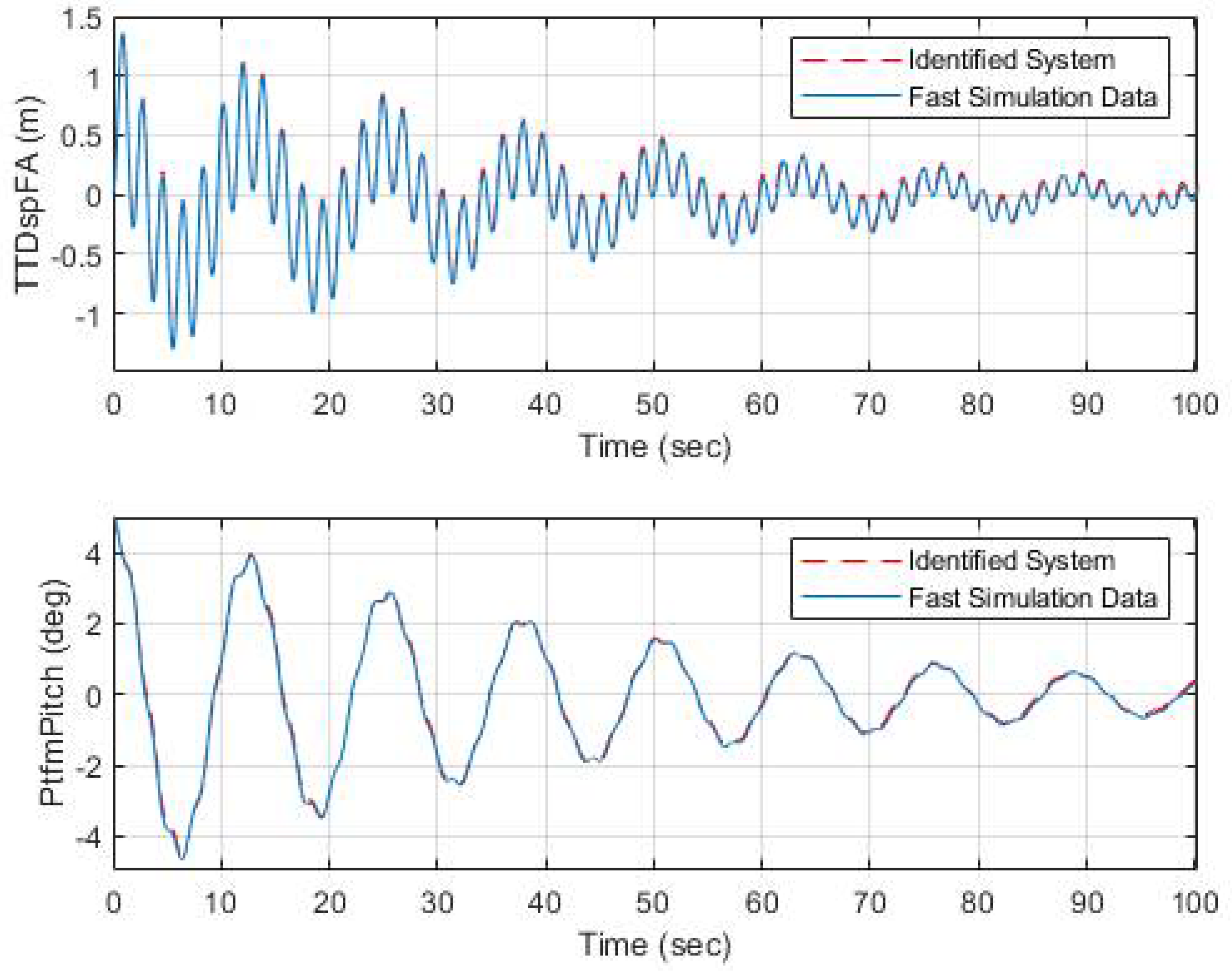
The validation of the FOWT model with the TMD with initial free decay of 5° is shown in
Figure 4. It is worth noting that this initial platform pitch angle is different from the angle used for the identification process, which was 3°.
As shown in
Figure 4, the response of the system simulated with FAST (red line) and the response of the obtained model (blue line) are practically identical. That is, the simplified model is capable of representing the non-linear behavior of the FOWT with respect to the most relevant variables, the fatigue of the tower (upper graph) and the pitch of the platform (lower graph).
In
Table 6, the precision of our identified model is compared to FAST-SC simulations and with the model described in [
11]. We use the identified model proposed in [
11] for the purposes of comparison. It is based on the same dynamics as ours, and it even uses the same algorithm. The data corresponds to a free-decay test of 100 s length, starting at 5° platform pitch angle, and using the TMD parameters proposed by Lackner and Rotea in [
32], that is, m
T = 20.000 kg, k
T = 5.000 N/m and d
T = 9.000 Ns/m.
The small absolute and relative errors shown in
Table 6 prove that the reduced model captures the main dynamics of the FOWT.
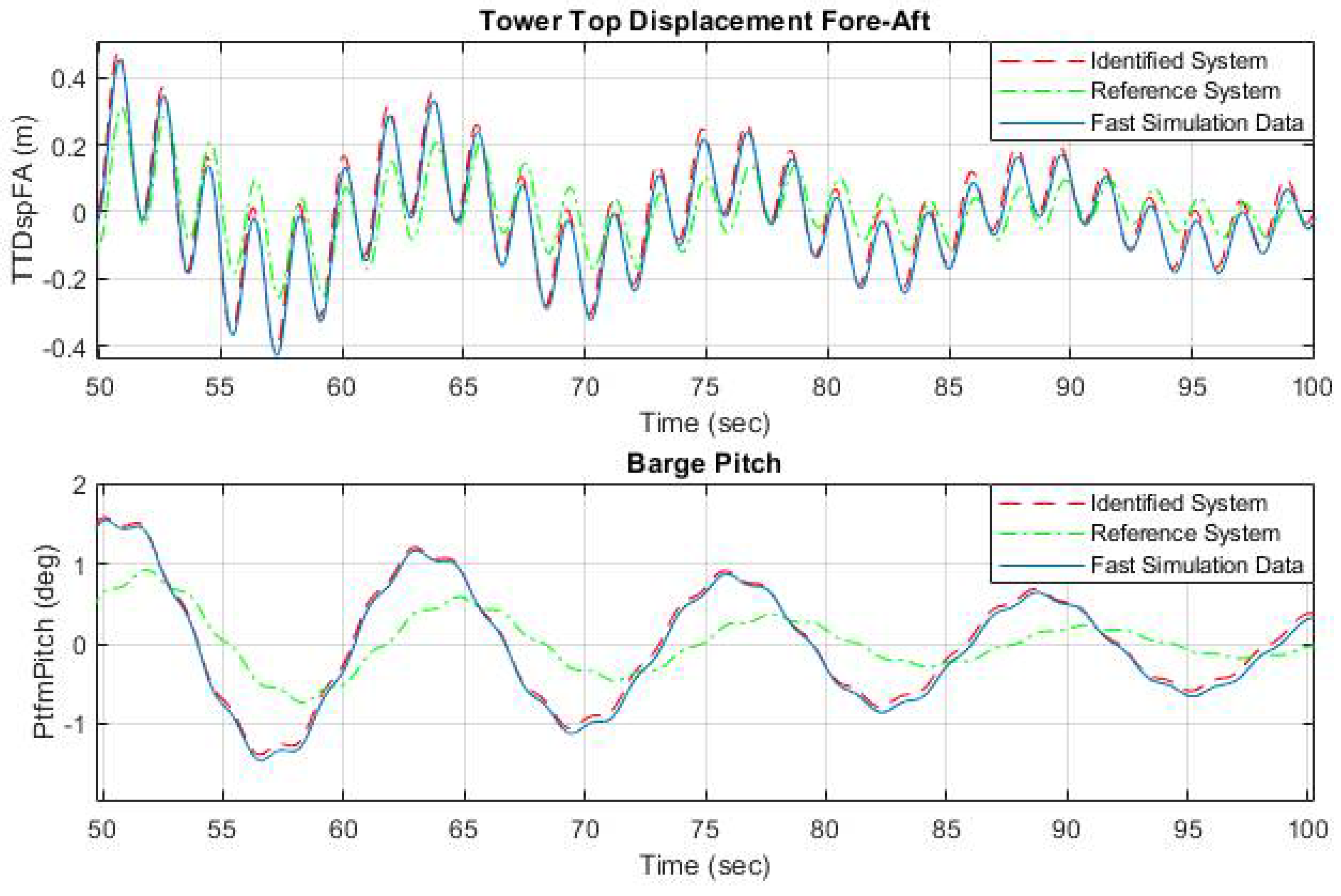
Figure 5 shows the responses, from 50 to 100 s, of the own identified model (red), the model identified in [
11] (green), and the FAST-SC one (blue), with the latter being considered the closest to reality. The simulations were carried out with the configuration used for validation, that is, initial platform pitch of 5° and the TMD parameters proposed by Lackner and Rotea [
32].
The responses of both models, the FAST and the proposed one, are similar throughout the simulation. However, although the model proposed in [
11] initially has the same behavior, it accumulates a drift error that deviates its response from the real system generated with FAST-SC.
Figure 5 shows that both the displacement of the tower top (upper graph) and the pitch of the platform (lower graph) are much better represented by the model identified here proposed than by that of [
11].
The difference in the results is due to the identification procedure. In [
11], the model is obtained from a single round of identification with 30 iterations of free decay simulations, with an initial platform angle of 5°. Furthermore, the authors state that they validate the wind turbine response using the TMD, but no correction is mentioned. The difference of the validation with respect to FAST, which is attributed to the non-linearities of the mooring loads, is also not quantified.
In
Table 7, the parameters of the selected model are presented.
7. Conclusions and Future Work
In this work, a general methodology for the identification of a reduced order dynamic model of a floating wind turbine is presented. The coupling between the floating platform and the wind turbine has been modeled using a linearized model. The main objective was to obtain a simple and computationally fast model of a barge-type WT.
The identification of the model parameters requires a baseline model of a FOWT that allows the generation of synthetic data. Simulations have been carried out with the FAST software to generate the wide range of data sets necessary for the identification and validation of the model. These data sets were obtained under different conditions to obtain identification solutions with different approaches. After evaluating the identification and validation results in three phases (algorithm, test duration, and initial platform pitch selection), the best estimate of the model parameters is obtained.
The model has been developed using the Matlab program, which is a much simpler software than FAST. Furthermore, the model, while still having less DOF, has proven to be accurate enough to be able to use in place of the much more complex FAST one. In addition, the model obtained allows us to easily interpret the dynamics of the system that is represented in the equations.
Moreover, the reduced model is linear. Therefore, it is easier to control and to integrate into any industrial controller. It requires less computational resources than the nonlinear model, although the computational cost will always depend on the hardware and software used.
The novelty of the proposed methodology lies in the iterative loop relationship between the identification and validation processes, fed by diversified data sets. The simplicity and precision of the resulting model is not only useful for conducting structural optimization research but can also be applied to reproduce the complex behavior of FOWT and integrate it into adaptive, model-based controllers.
Another advantage of the identification methodology proposed here is that it can be implemented with any computer program or language, on any hardware. That is, it is not a closed software package, like FAST, that does not allow any changes.
However, the main drawback of this identification methodology is that it does not include the impact of waves and wind. The FAST package has more modules to it, and therefore can test the system in more realistic scenarios, although we have simulated a free decay of the platform. Another weak point of the proposal is that our reduced model unifies the different dynamics of the model, that is, it considers time constant in all the different processes of the system.
In future work, as the model is scalable, a possible extension could be to apply the identification methodology to two wind turbines that are on the same barge, or on a different barge type floating wind turbine. Different floating foundations (spar-buoy, tension leg) can also be tested. A relevant step forward would be to characterize the FOWT response including environmental loads, mainly wind and waves. Furthermore, the model could be used to test different structural control strategies. Finally, it would be desirable to validate the results with a scale prototype of a wind turbine or with real data.


